Article

Numerical Study of Bearing Capacity of the Pile-Supported Embankments for the Flexible Floating, Rigid Floating and End-Bearing Piles

1
College of Civil Engineering, Taiyuan University of Technology, Taiyuan 030024, China
2
School of Civil Engineering and Architecture, Hubei University of Technology, Wuhan 430068, China
3
Key Laboratory of Concrete and Prestressed Concrete Structures of Ministry of Education, School of Civil Engineering, Southeast University, Nanjing 210096, China
*
Author to whom correspondence should be addressed.
Symmetry 2022, 14(10), 1981; https://doi.org/10.3390/sym14101981
Submission received: 12 July 2022 / Revised: 7 September 2022 / Accepted: 9 September 2022 / Published: 22 September 2022

Abstract

:
Floating pile-supported embankment involves more complex load transfer mechanisms, and there are no clear uniform guidelines available for its design. The concepts of flexible floating, rigid floating and end-bearing pile-supported embankments were proposed in this paper. Based on three typical field cases, their pile-soil interactions and soil arching effect were examined using the three-dimensional finite element method. Due to symmetry, only a half-width embankment model was simulated here. It has been found that the flexible floating piles carry the load mainly relying on the skin friction, but end-bearing piles rely on the pile tip resistance. The rigid floating piles were somehow in between. The earth pressure coefficient (K) in the end-bearing pile-supported embankment reached a maximum of 3.28, greater than Rankine passive values of the earth pressure coefficient (KP), in which the soil arching was fully developed. The K in the embankment with rigid floating pile reached 2.21, where soil arching might be partially formed. At the bottom of the flexible floating pile-supported embankment, the K tended to equal the Rankine active values of the earth pressure coefficient (Ka), and thus soil arching was insignificant. It has also been found that using rigid floating piles might significantly improve the bearing capacity of the embankments and was cost-effective for deep soft soil areas.

1. Introduction

The piles supporting the embankment usually penetrate through the soft soil standing on a stiff stratum [1,2,3,4,5,6], which facilitates the piles to transfer the embankment load as well as the traffic load to the deep bearing layer. Penetrating through the soft soil may be quite cost-consuming once the thickness of the soft soil is large, for which the floating piles provide a choice.
Floating piles are divided into two types, i.e., flexible floating piles and rigid floating piles, according to the bearing capacity of the soil layer on which the pile tip is located. In addition, the materials and sizes of the piles need to be considered; flexible floating piles (Figure 1a), where the pile tip does not reach the stiff stratum, such as the silty clay [7]. The stone piles, cement mixing piles and jet grouting piles are often used for flexible floating piles [8,9,10], and the pile caps are usually absent. Unlike the flexible floating pile, the rigid floating piles (Figure 1b) usually have a tip that reaches the medium-stiff layer. Pipe and cement mixing piles are common rigid floating piles [11]. The pipe piles further improve the side friction resistance and boost the bearing capacity. The end-bearing piles (Figure 1c) are generally constructed with concrete materials [12,13]. However, the floating piles were not classified by general design standards, and there was no clear distinction in engineering. The French guideline [14] only classifies piles into floating and rigid (end-bearing) piles. It proposes that some findings can be considered as valid solely for rigid piles lying on a resistant substratum (and in theory does not apply to the floating piles). The German standard EBGEO [15] suggests that the design of embankments on floating piles should be further investigated. Similar recommendations were made by Satibi [16] and van Eekelen et al. [17]. Xu et al. [18], Bhasi and Rajagopal [19], and Pham [20] investigated the load transfer mechanism of floating piles, respectively, using centrifuge test, numerical study and analytical solution. The piles whose tips do not reach the firm stratum were simply regarded as “floating piles” by them, being consistent with some existing research (e.g., Hong et al. [21]; Yadav et al. [22]; Wang and Zhang [23]; Shen et al. [24]). Although several studies on this topic have been conducted by many researchers [25,26,27], the mechanism of different floating piles to carry load remains uncertain and further studies need to be performed.
The soil arching is the fundamental load transfer mechanism involved in the pile-supported embankment, which has been well recognized in many studies [28,29,30,31,32,33,34]. Terzaghi [28] early demonstrated the soil arching by performing the “trapdoor” test. Hewlett and Randolph [29] proposed that the soil arch in pile-supported embankments is a semicircle of equal thickness in the two-dimensional (2D) case and a hemispherical shell of equal thickness in the three-dimensional (3D) case. Zhuang and Cui [30] modified both the thickness of the arch and the earth pressure coefficient of embankment fill in the Hewlett and Randolph model, making it more consistent with the actual conditions. Zhuang and Wang [31] investigated the soil arching in highway pile-supported embankments subjected to moving vehicle loads. However, most of these studies were conducted on end-bearing piles or rigid supports. Few studies focus on soil arching in floating pile-supported embankments. The British Standard BS8006 [32] is widely accepted for the design of the pile-supported embankment, which only roughly describes that floating piles may weaken the soil arching. The soil arching in the floating pile-supported embankments was explored in the numerical analysis [19]. However, only the effect of pile length was discussed. Therefore, a clear classification design guideline for floating piles and their bearing mechanism requires further investigation.
In this paper, the 3D model was developed to investigate the behavior of a pile-supported embankment. The concept of the flexible floating pile and the rigid floating pile was proposed in this study. The type of the piles was distinguished according to the bearing capacity of the subsoil on which the pile tip locates, the pile dimensions, the pile material and the piling method. Three typical field cases, including flexible floating piles, rigid floating piles and end-bearing piles, were investigated in terms of load-bearing mechanism. The pile-soil interaction and soil arching effect of pile-supported embankments were examined in detail under different pile types. A guideline for practical engineering is expected to be provided after this study is performed.

2. Three Typical Field Cases Studies

The finite element method (FEM) has become robust for analyzing engineering problems. Abaqus [35] was used for the finite element (FE) analysis of the pile-supported embankment in this research. To verify the accuracy and reliability of the modeling approach, three typical field cases were adopted which correspond to flexible floating piles, rigid floating piles, and end-bearing piles, respectively. Based on the cases mentioned above, the pile-soil interactions and development of the soil arching for three varied types of piles were investigated.

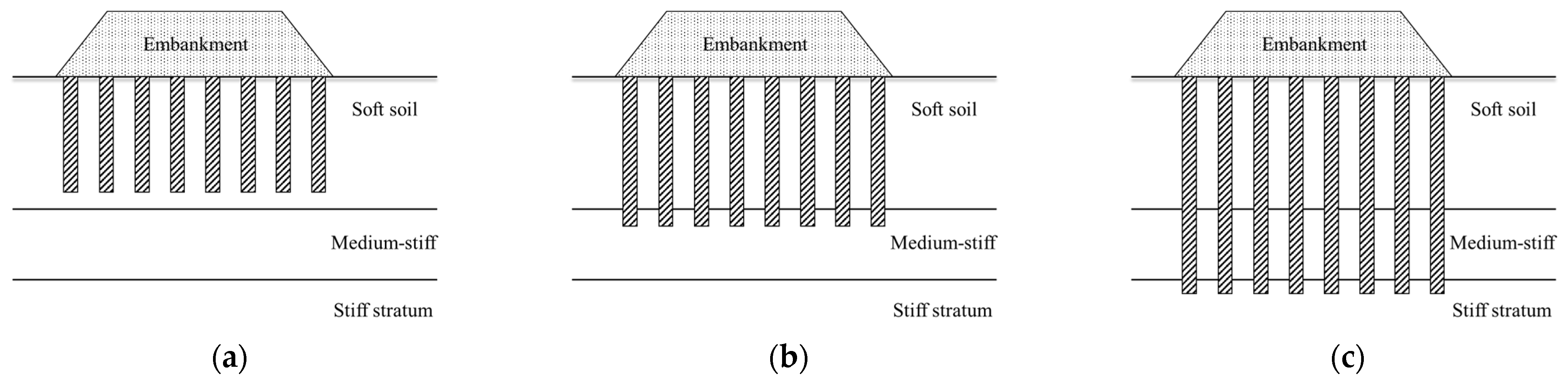
2.1. The Flexible Floating Pile

2.1.1. Site Conditions

Jamsawang et al. [8] reported a field test on a pile-supported embankment located at Station KM6 + 055 of highway No. 3117 in Thailand. The embankment height was 1.5 m with a 12 m crest width, and the side slope ratio was 1(V): 2(H). The groundwater level was near the surface of the subsoil. Deep cement mixing (DCM) piles were used with a length of 14 m and a diameter of 0.6 m. Piles were placed in a square pattern and the center-to-center pile spacing was 1.5 m without the pile caps. They, therefore, were flexible floating piles.

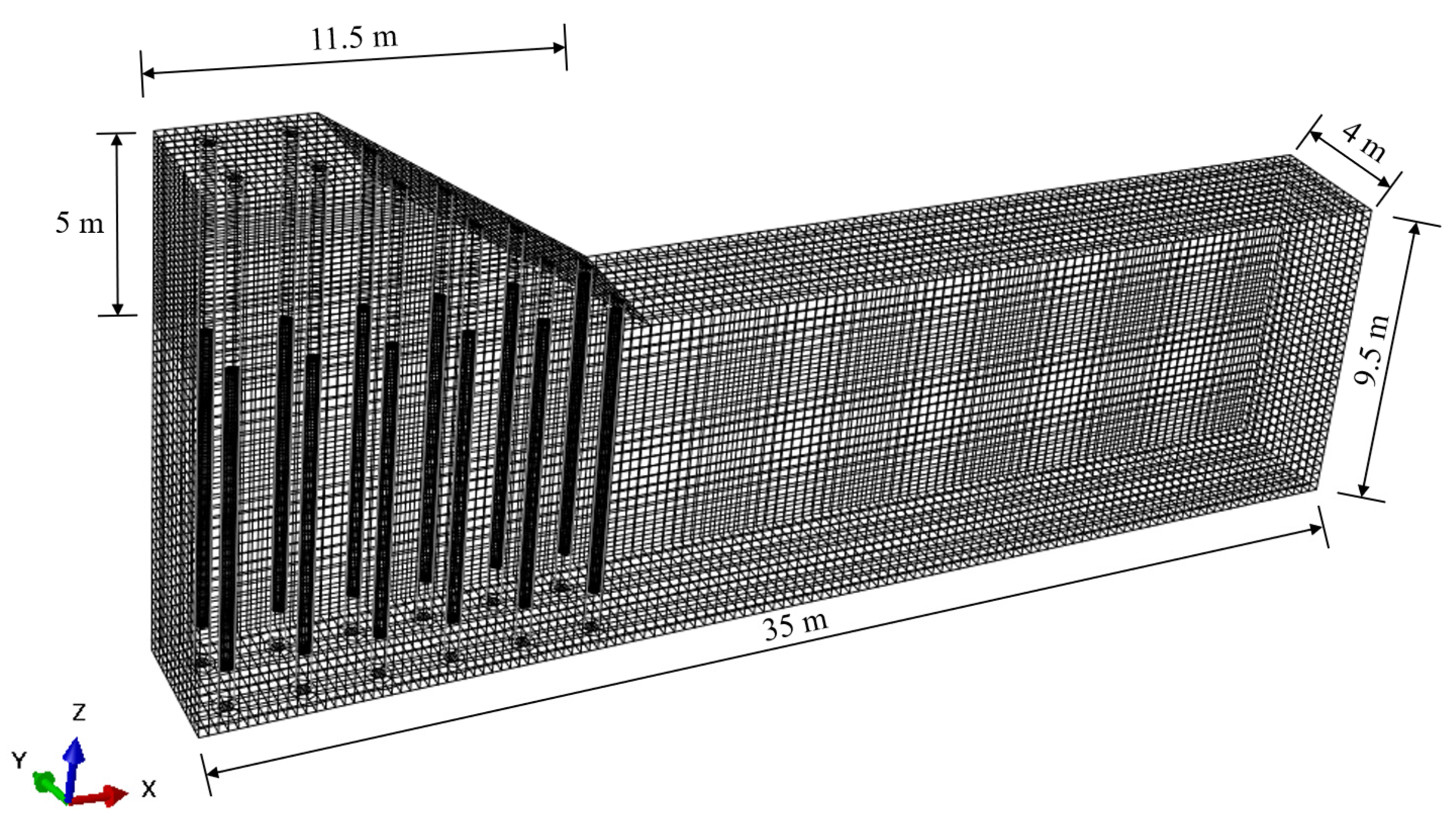
2.1.2. Finite Element Model

The full 3D embankment model usually requires long computation time and good computer performance [36,37]. Therefore, a simplified 3D slice model of a half-width embankment was built here (Figure 2). The centerline of the embankment was used as a boundary of the model due to the symmetry. To minimize the boundary effects, the lateral (perpendicular to the direction of travel) width of the model was more than three times the bottom width of the embankment. The dimension of the slice model in the direction of the traveling was double the net pile spacing (i.e., 3 m). Two rows of piles were simulated in the traveling direction under a rectangular pattern of the pile placement.
In the flexible floating pile model, The DCM pile has a unit weight of 15 kN/m3. The elastic modulus and the Poisson’s ratio of the pile were 80 MPa and 0.33, respectively. The FE parameters of embankment fill and subsoil are given in Table 1. The piles were assumed to be impermeable, while the subsoil above the groundwater table and the embankment fill were presumed to be highly permeable. They were all discretized using 20-node quadratic brick elements with reduced integration (C3D20R). The subsoil below the water table was meshed using a 20-node brick with pore pressure, quadratic displacement, linear pore pressure and reduced integration (C3D20RP) to simulate the coupled mechanical and hydraulic behavior of the subsoil. The Modified Cam-clay (MCC) model was adopted for the response of subsoil, while the Mohr-Coulomb (MC) model was used for describing the behavior of the embankment fill. The displacement in the x, y and z directions was controlled to be 0 at the bottom of the model (z = 0). The displacements normal to the side planes were set to be zero. Free drainage boundary was applied at the water table surface. The vertical boundaries and the bottom of the model were impermeable.

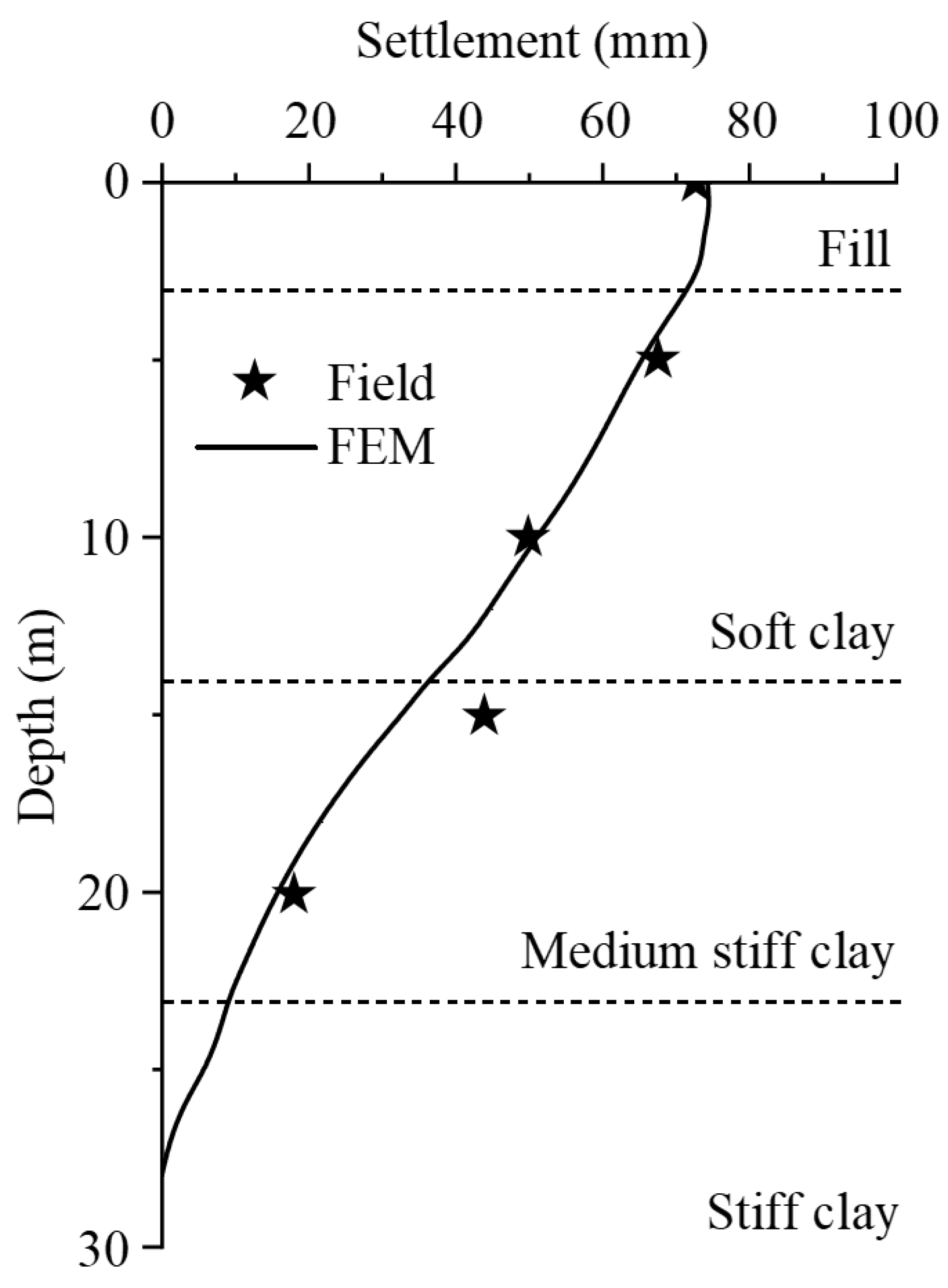
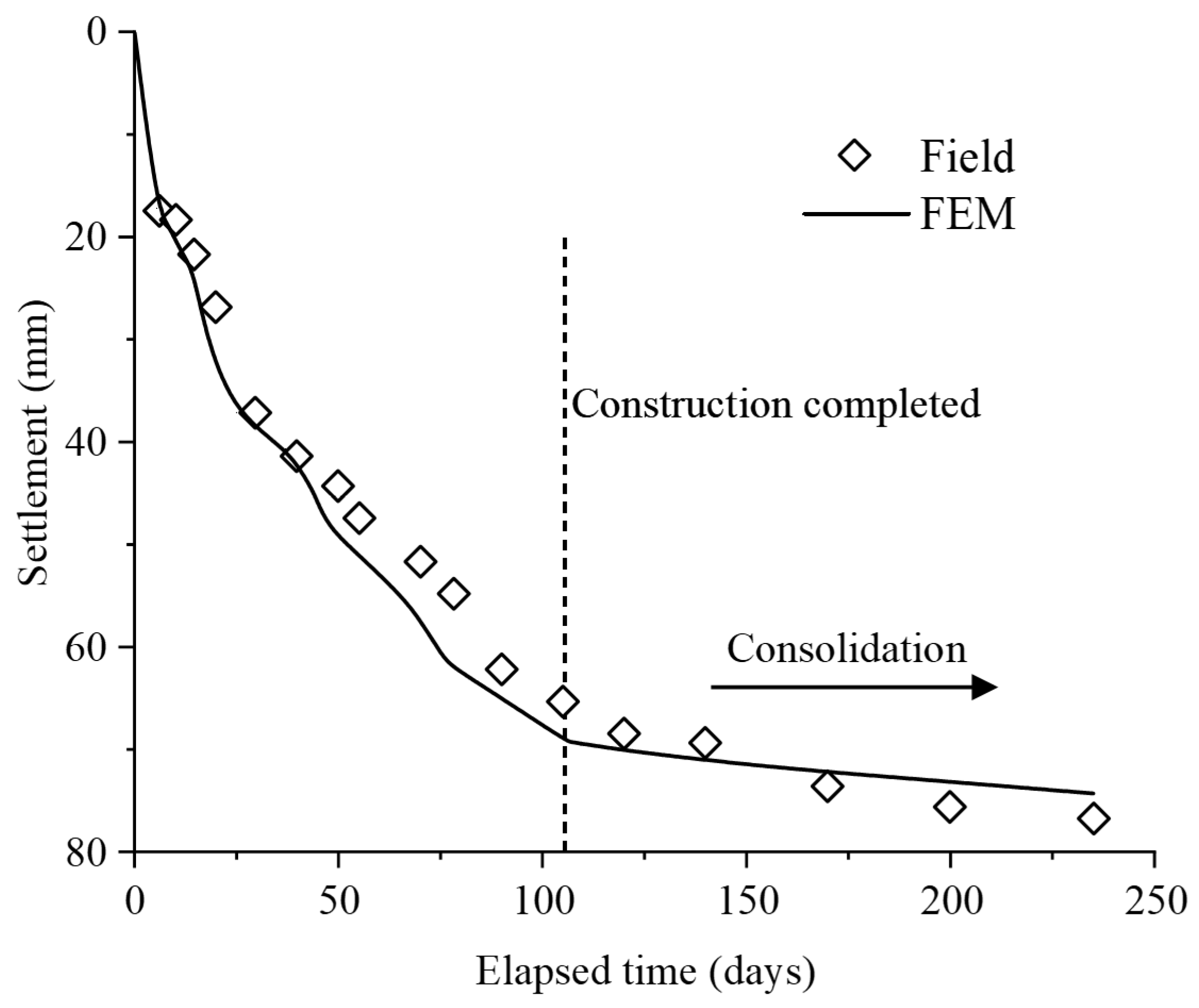
2.1.3. Model Validation

Field tests were conducted on the flexible floating pile-supported embankment and the embankment settlement and stress were monitored for 235 days initiating from the construction of the embankment. Figure 3 shows the field measured and FE computed surface settlement near the centerline of the subgrade in 235 days. The surface settlement reached 66 mm and 78 mm at the end of construction and 235 days after the construction. At the same time, the corresponding FE computed settlements were 69.1 mm and 74.3 mm, respectively, yielding an error of less than 5%.
Figure 4 shows the subsoil settlement versus depth on the 235th day after construction. The FE results were in good agreement with the field measurements. It was found that the settlement of the “soft clay” layer and “medium stiff clay” layer accounts for 75% of the total subsoil settlement. The settlements of the “soft clay” layer and the “medium-stiff clay” layer were close, about 30 mm. The FE analysis results were reasonable in comparison with the field measurements, indicating that the FEM here is capable of simulating the performance of flexible floating piles.

2.2. The Rigid Floating Pile

2.2.1. Site Conditions

The construction of an embankment in the northern suburb of Shanghai [11] was adopted as the case study of rigid floating piles. The embankment was constructed in 55 days, approaching a height of 5.6 m with a side slope ratio of 1(V):1.5(H). The crest width of the embankment was 35 m. The soil profile of the site from top to bottom was 1.5 m thick coarse-grained fill, 2.3 m thick silty clay, 10.2 m thick soft silty clay, 2 m thick medium silty clay, and sandy silty below. The embankment was supported by cast-in-place concrete pipe piles of having a length of 16 m. The piles ended at a relatively stiff sandy silt layer. Each pile had an outer diameter of 1.0 m and the net pile spacing was 3.0 m. The thickness of the pipe pile was 120 mm. A 0.5 m thick reinforced cushion consisting of two 0.25 m thick gravel sandwiched by a biaxial polypropylene geogrid was placed at the bottom of the embankment.

2.2.2. Finite Element Model

The model configuration of the rigid floating pile adds reinforcement based on the flexible floating pile (Figure 5). The reinforcement was modeled using 8-node quadrilateral membrane elements with reduced integration (M3D8R), and the reinforcement was assumed to be isotropic. The mechanical response of the piles and reinforcement were assumed to follow the linear-elastic model. The tensile strength of the geogrid was 90 kN/m in both directions. The detailed parameters of the soil layers and piles are shown in Table 2.
The surface-to-surface contact interaction was used to define the interaction between the reinforcement and embankment fill and between the piles and subsoil. The surface-to-surface contact interaction in Abaqus [35] describes the contact between two deformable surfaces or between a deformable surface and a rigid surface, called contact pairs. The contact interaction property was defined as tangential behavior using Coulomb friction and normal behavior using “Hard” contact and no separation after contact was allowed. With regard to the friction coefficient μ , μ R = tan φ f was used for the reinforcement and embankment filler, while μ P = tan 0.7 φ s was used for pile-soil interaction, where φ f is the effective friction angle of the fill, φ s is for subsoil.

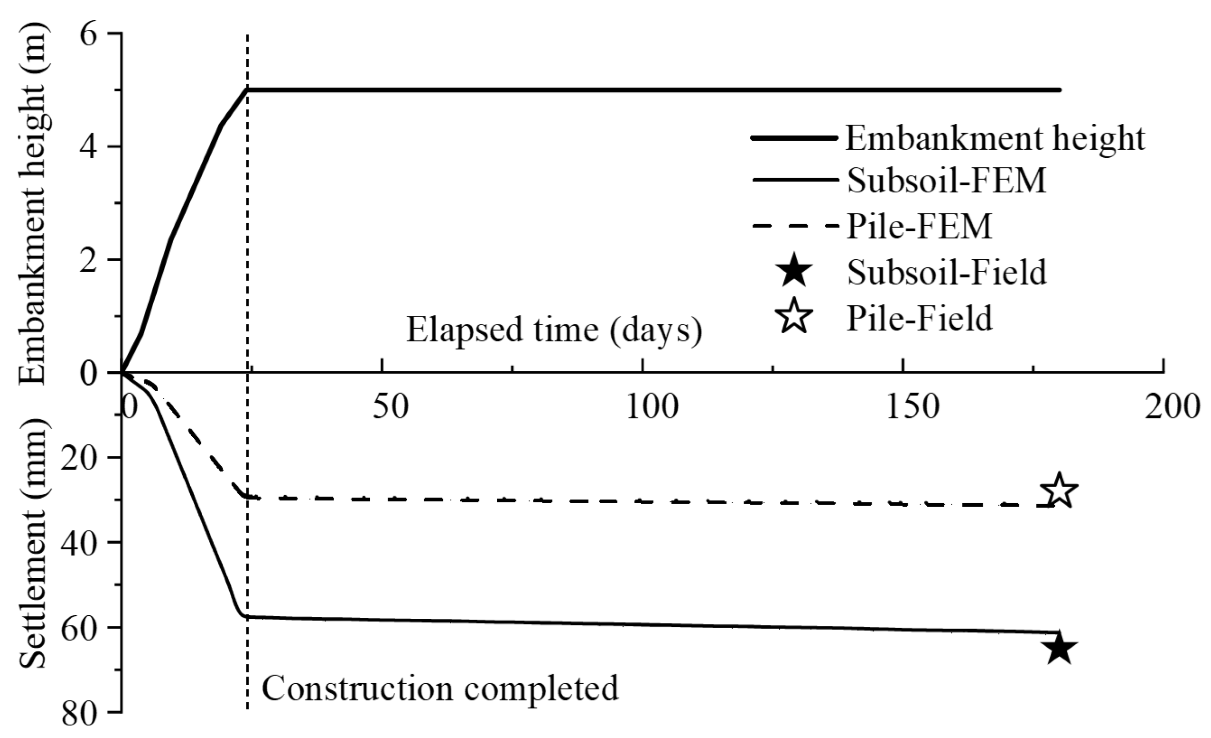
2.2.3. Model Validation

The field monitoring collected data for 180 days from the start of embankment construction. The settlement was measured using surface settlement plates on the top of the piles and the subsoil surface near the embankment centerline. It is not surprising that the largest settlement of the subsoil occurred at the center of the four adjacent piles. At the end of the embankment construction, the maximum settlements of the pile top and the soil surface were 14 mm and 63 mm, respectively. At the end of the field monitoring (125 days after the completion of construction), the measured maximum settlements increased to 19 mm and 87 mm, respectively, due to consolidation. Figure 6 shows the results of field tests and FE analysis of the settlements on the pile top and subsoil surface. It was found that the FE computed results of pile top settlements were 12.6 mm and 19.6 mm at the end of embankment construction and the end of field tests, yielding an underestimation of 11.1% and an overestimation of 3.1%. The subsoil surface settlements from FE analysis were 65.8 mm and 85.4 mm, causing an overestimation of 4.4% and an underestimation of 1.9%. The result demonstrates that the FE modeling performs well for simulating rigid floating piles.

2.3. The End-Bearing Pile

2.3.1. Site Conditions

To investigate the performance of the pile-supported and geosynthetic reinforced embankment built on the soft ground, Rowe and Liu [12] performed a field test used here for the third study case. The construction site is located 20 km northeast of Paris with four instrumented sections, and section S4 was selected as the end-bearing pile case study. The embankment height was 5 m, accompanied with an 8 m crest width and the side slope ratio of 1(V):1.5(H). The subsoil was as deep as 9.5 m which was divided into seven layers. The groundwater table was 2 m immediately below the subsoil surface. The piles had a length of 8.3 m and a diameter of 0.38 m, and they were placed in a square configuration spacing at 2 m. The geogrid was sandwiched in a 0.55 m thick gravel cushion.

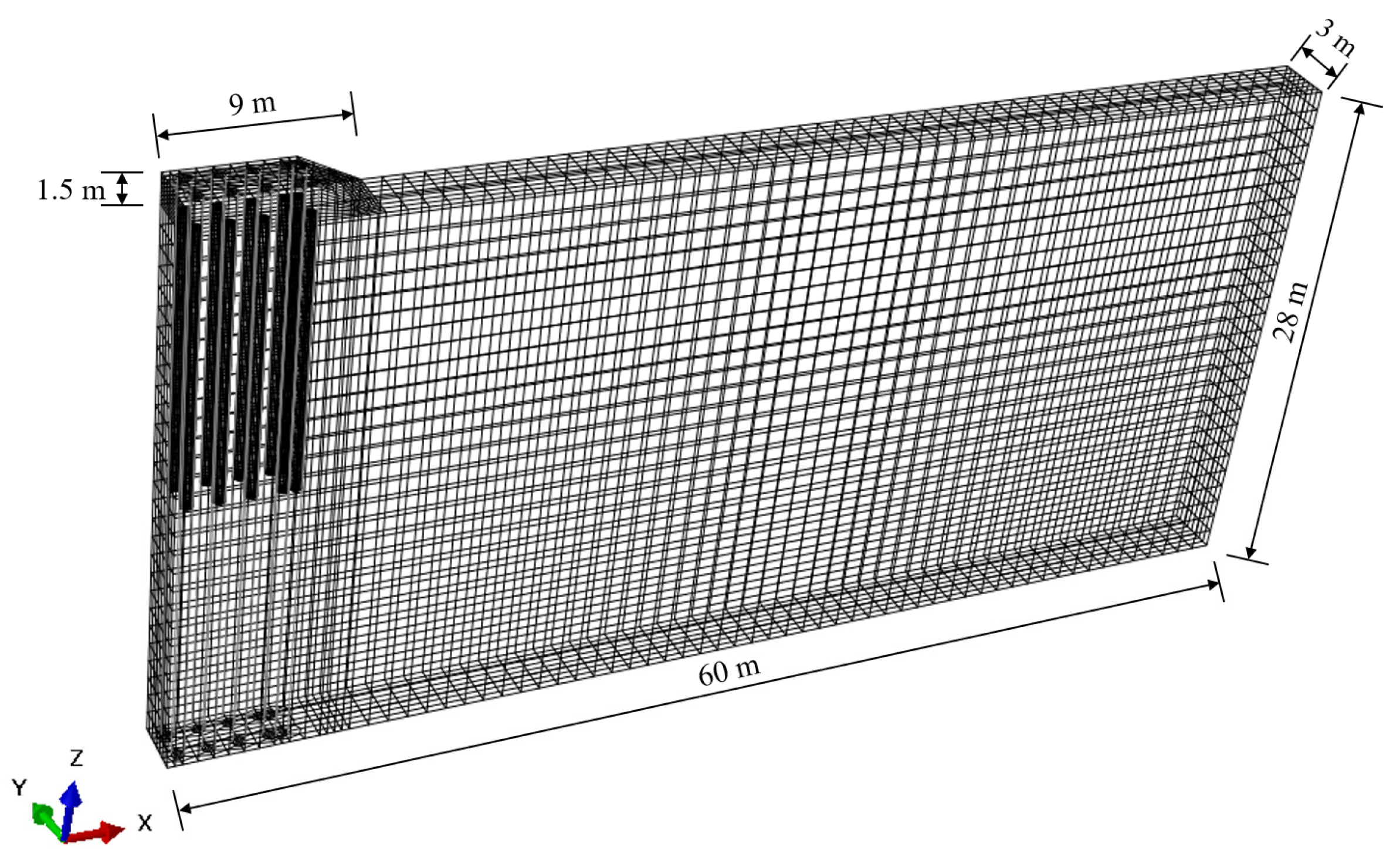
2.3.2. Finite Element Model

For end-bearing piles, the modeling method is the same as that for rigid floating piles. Figure 7 shows the finite-element model used in the analyses. The detailed parameters of each sub-layer are given in Table 3. The geogrid was assumed to be isotropic with a tensile stiffness of 500 kN/m. The properties of the gravel cushion, embankment fill and piles are given in Table 4.

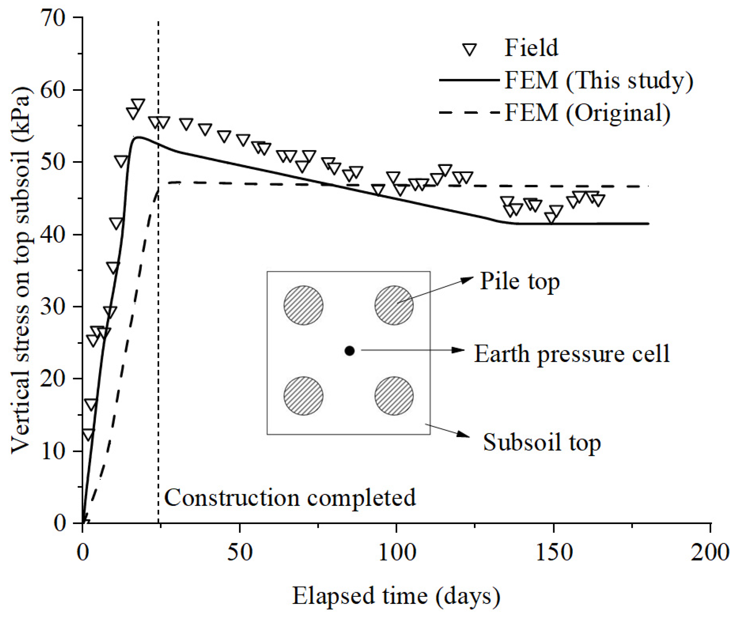
2.3.3. Model Validation

There was no field data on the pile and soil monitoring for settlement with time, except for the final settlement in the field measurement from Briançon and Simon [38]. Therefore, the FE computed results were only compared with the final measured settlement, see Figure 8. It has been found that the final settlements of the pile top and subsoil surface were 31 mm and 61.2 mm, respectively, which were 10.7% higher and 6.2% lower than the field measurement, showing a good agreement. Figure 9 shows the variation in vertical stresses exerted on the center of the subsoil surface enclosed by four adjacent piles with the elapsed time, including the results of the FEM analysis in this study, the field data and the original numerical results of Rowe and Liu [12]. The results show that the results of the FEM analysis in this study well capture the evolution of the field test data.

3. Results and Discussion

3.1. Pile-Soil Interaction

The different pile-soil interactions lead to the load transfer mechanisms of the three types of piles remaining different. The distribution of the skin friction and axial force of the three types of piles were investigated to explore their load-bearing mechanisms.

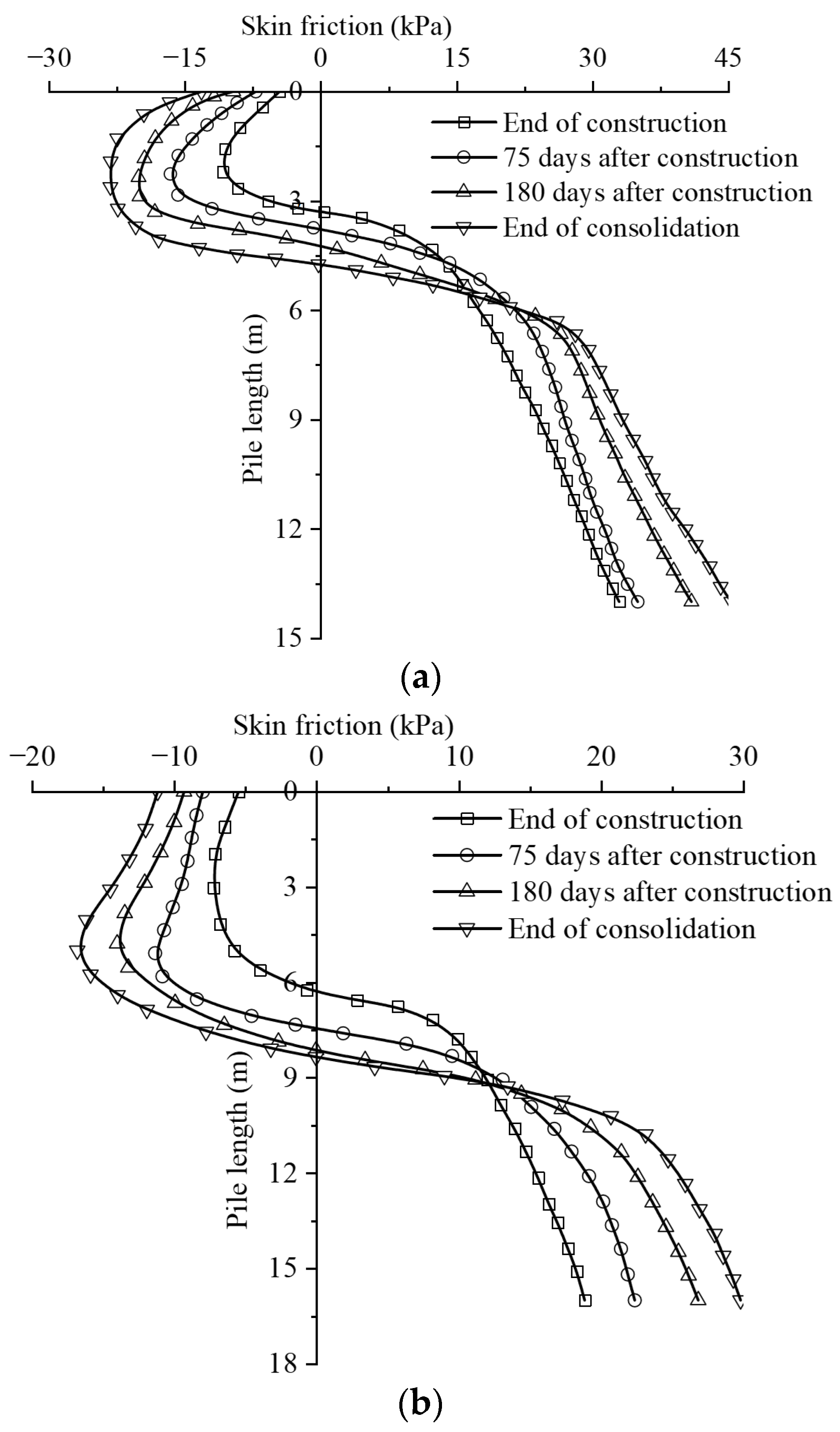
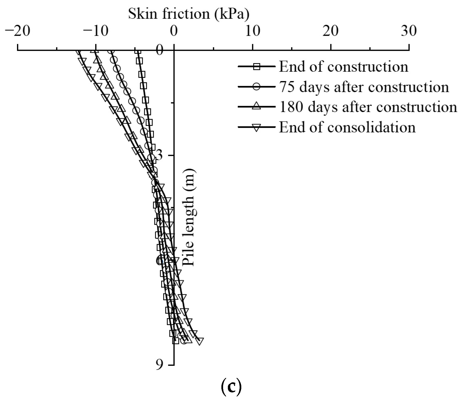
3.1.1. Skin Friction of the Pile

The consolidation of the subsoil in proceeds and thus settlement occurs under the embankment load. When the settlement of the pile is less than the subsoil, negative skin friction applies resistance to subsoil settlement. The reaction load acting on the pile caused by the resistance may increase pile settlement. When the settlement of the pile is greater than the surrounding subsoil, the pile imposes positive skin friction on the subsoil, which is, however, beneficial to restrain the development of pile settlement. For a floating pile, the settlement of the subsoil around the upper part of the pile is larger than the subsoil, and thus the negative skin friction generates along the upper surface of the pile. For an end-bearing pile, the pile movement is small because the pile tip stands on the firm stratum, and the negative skin friction is usually distributed along the whole length of the pile.
Figure 10 shows the variation in the skin friction of the three types of piles along the pile length. The skin friction force of the flexible floating pile was the largest, 50% larger than that of the rigid floating pile and twice that of the end-bearing pile. For flexible and rigid floating piles, both the negative skin friction in the upper part and the positive skin friction in the lower part increase with the development of soil consolidation. The floating pile’s neutral plane (at which the friction resistance is 0) moves downward as consolidation proceeds. At the completion of consolidation, the neutral plane of the flexible floating pile reaches a depth equaling 1/3 of its length, and that of the rigid floating pile reaches 0.5 times its length. In the case of end-bearing piles, almost no positive skin friction was generated along the entire length of the pile. The neutral plane was firstly appearing at the pile tip when the embankment construction was completed. Then roughly moved upwards as consolidation proceeds, reaching a depth equaling 3/4 of pile length when the subsoil consolidation was completed.

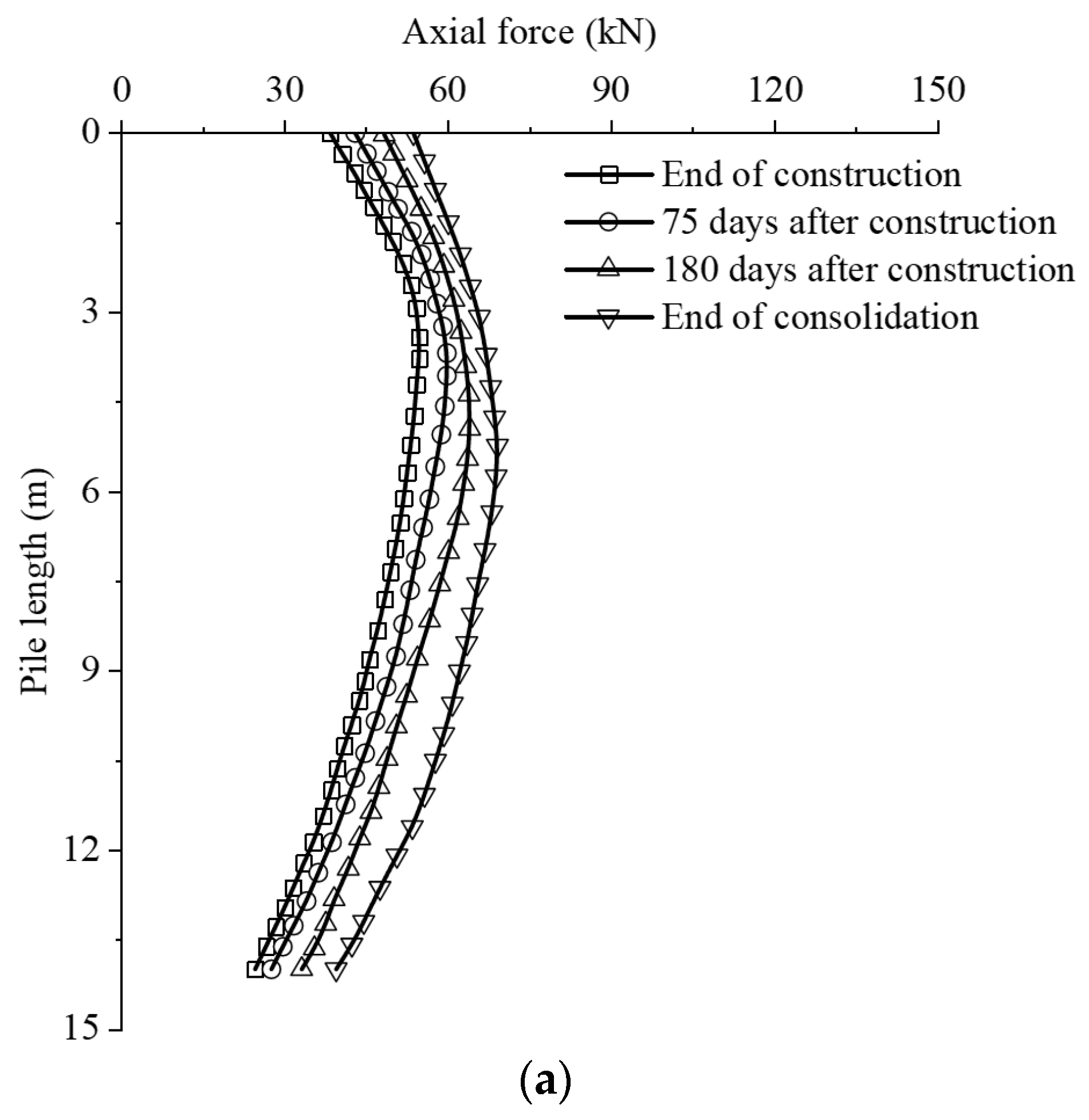
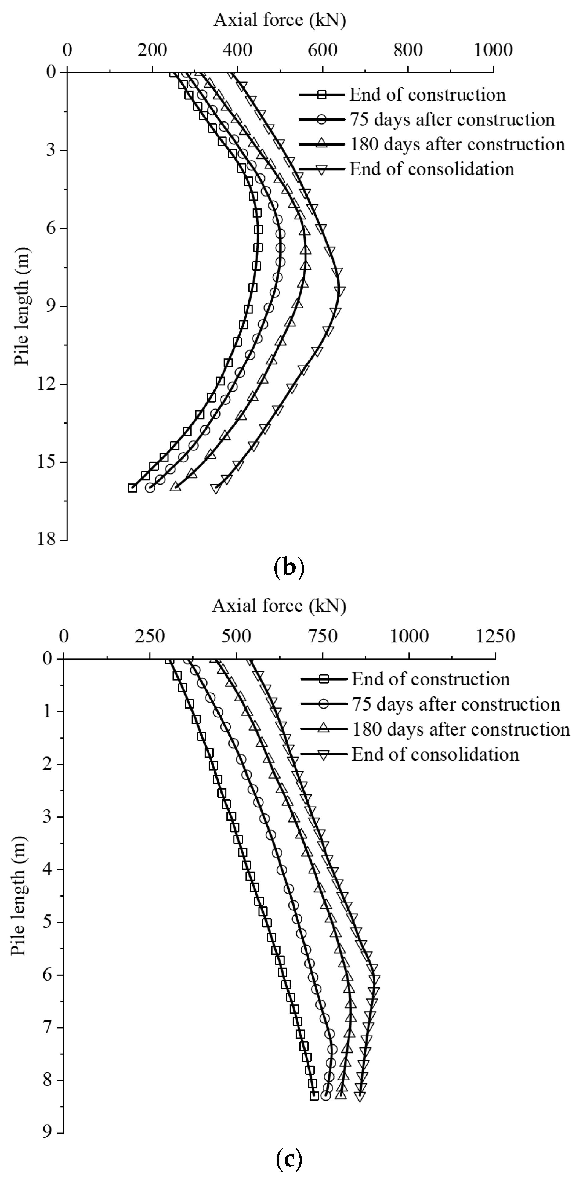
3.1.2. Axial Force Distributions along with the Pile

Axial force plays an important role in investigating the bearing mechanism of pile-supported embankments. For three types of piles, the axial force increases as soil consolidation evolve (as shown in Figure 11). It tends to increase and then decrease along the pile length, reaching the maximum values at the neutral plane. The flexible floating pile has the lowest axial force, only 10% of the end-bearing pile. The axial force of rigid floating piles is 71% of that of end-bearing piles. It has been found that flexible floating pile induced the largest pile-side skin friction but the lowest axial force. It may mainly depend on the frictional resistance to resist embankment loads. The end-bearing pile yields the highest axial force, it mainly relies on the tip resistance to carry the load. The load-carrying mechanism of rigid floating pile was in between.

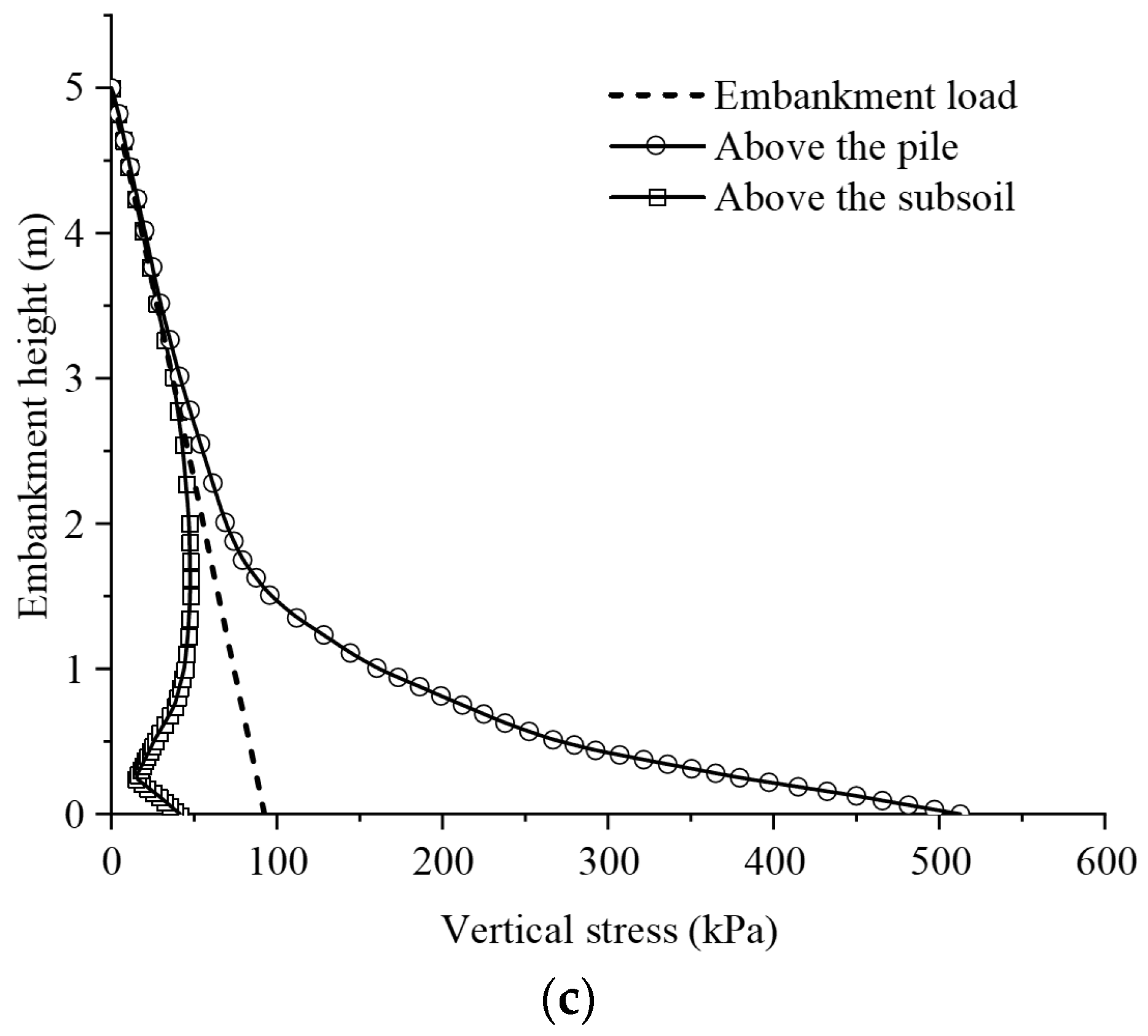
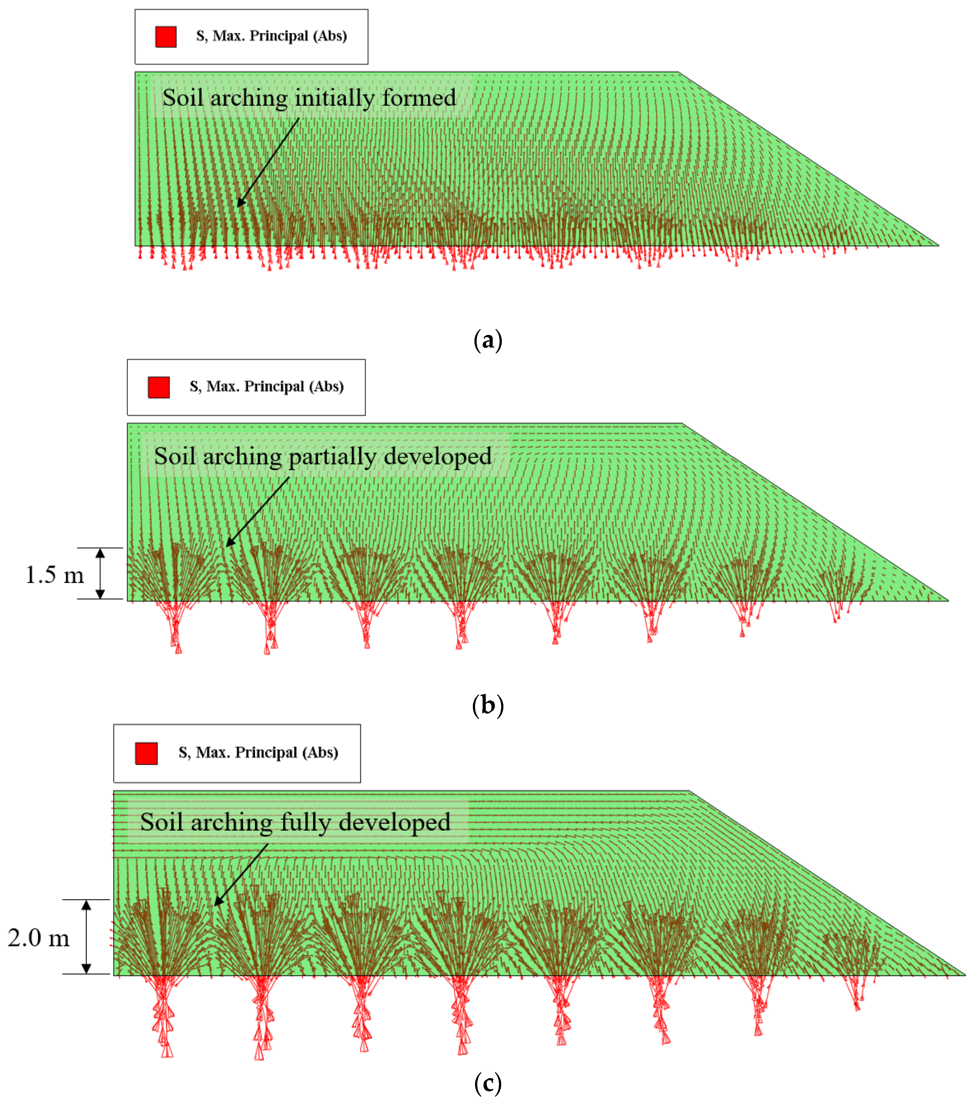
3.2. Development of Soil Arching

Differences in pile-soil interactions between floating and end-bearing piles have implications for the development of soil arching. This section investigated stress reduction ratio, earth pressure coefficient, and differential settlement in the embankment with varied piles types.

3.2.1. Stress Reduction Ratio

Stress reduction ratio (SRR), defined as the ratio of vertical stress exerts on the subsoil surface over embankment load, is usually used to evaluate the level of load transfer to the pile (the level to which the soil arching develops). The expression is as follows:
S R R = σ S γ h
where γ is the unit weight of the embankment, h is the height of the embankment, and σ S is the vertical stress exerts on the subsoil surface.
Figure 12 shows the variation in vertical stresses along with embankment height above the subsoil at the center of four piles and piles (points A and B in Figure 13) for three models. The data are acquired when the consolidation is completed. The results show that in the upper of the embankment, the vertical stresses above the two points were equal to the self-weight of embankment. With the embankment depth increasing, the vertical stresses above the subsoil decrease, while the stresses above the piles increase, which benefitted from the soil arching in the embankment. It has been found that the stress above the rigid floating and end-bearing piles increased rapidly along with the depth of the embankment, while the increase in the vertical stress above the flexible floating piles was not as significant as that in the embankment involving the other two types of piles. It has also been found that the stress at the subsoil surface of the flexible floating pile (Figure 12a) was close to the self-weight of embankment with SRR = 0.90, and the arching was insignificant. The rigid floating pile improved the stress transfer with SRR = 0.61, in which the soil arching might be partially developed. The end-bearing pile yields an SRR of 0.44 and a full soil arching was achieved.

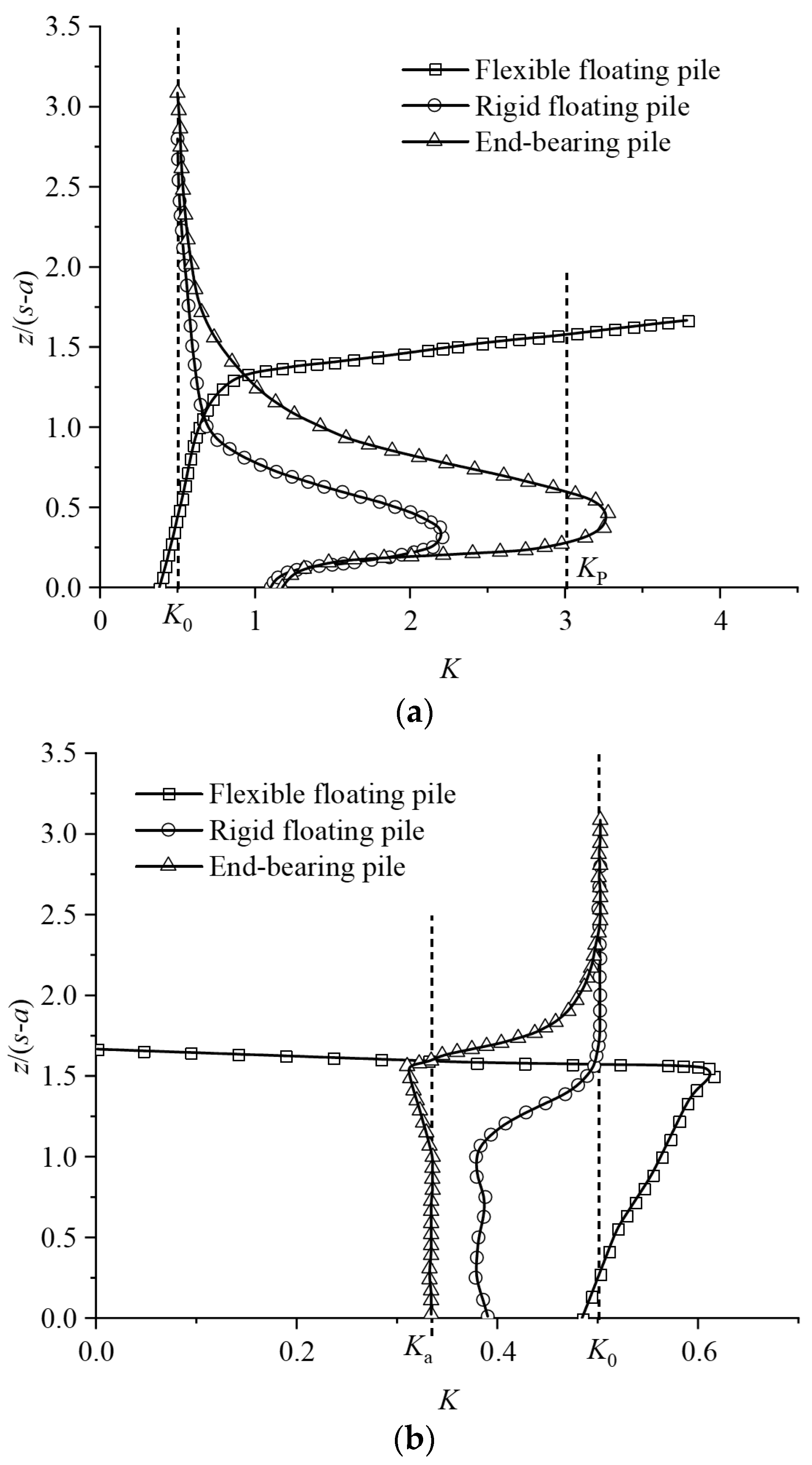
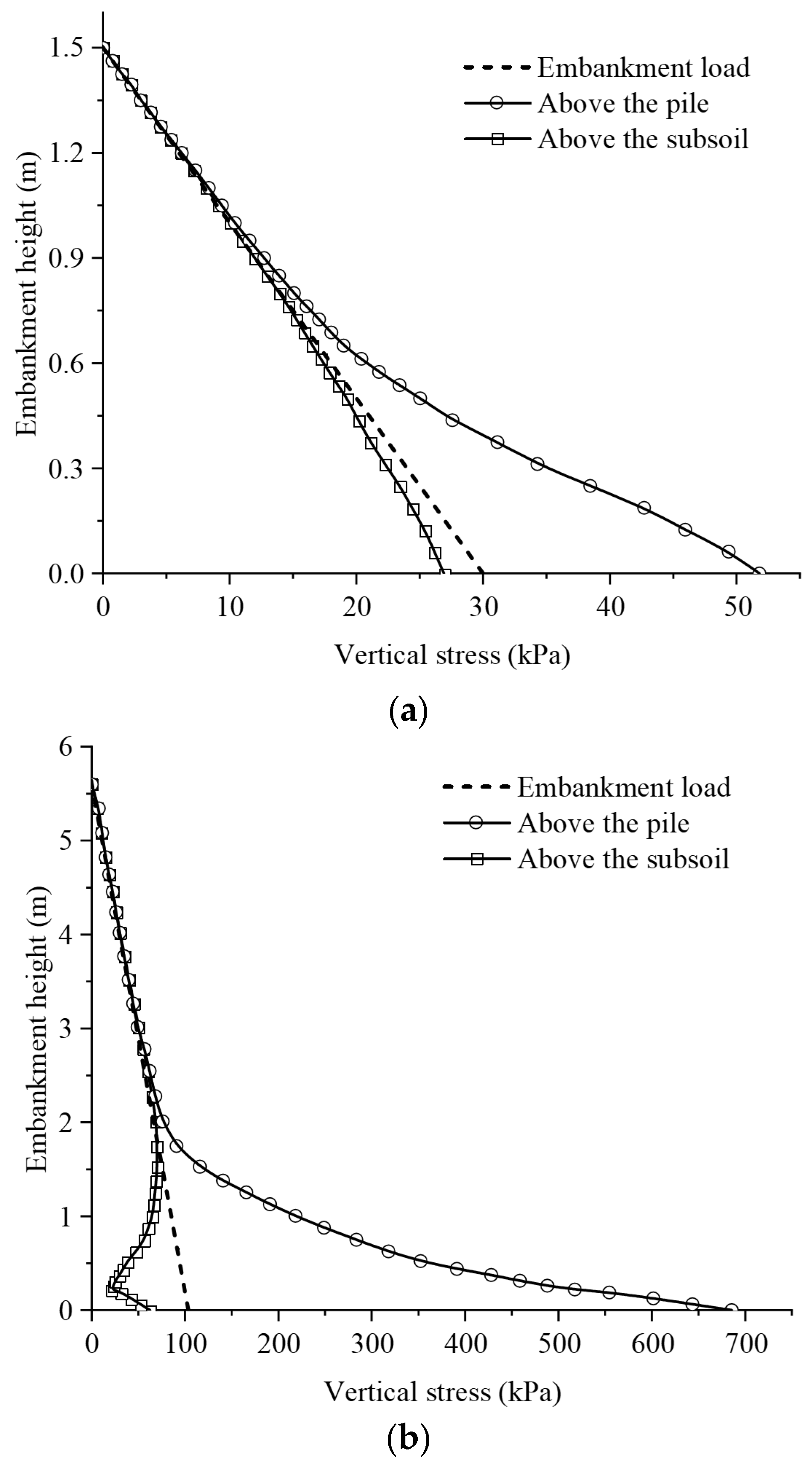
3.2.2. Earth Pressure Coefficient

Figure 14 shows the lateral earth pressure coefficient (K) at the vertical profile through points A and B (in Figure 13) in the embankment. Where z is the height above the base of the embankment, and s and a are the pile spacing and the diameter, respectively. The horizontal stress was considered to be independent of direction. The Rankine active and passive values of the earth pressure coefficient (Ka and KP) are plotted in Figure 14 using dotted lines. The formula for calculating K is shown in Equation (2).
K = σ h σ v
where σ h is the horizontal stress at a point in the embankment, σ v is the vertical at the point.
It has been found that the K in the embankments involving the rigid floating piles and end-bearing piles followed a similar evolution trend (Figure 14a). At the surface of the embankment, the K tended to K0 with the increase in height. In the lower part of the embankment, the K increases to the extreme value point with the increase in depth, then decrease with depth. Unusually, the K in the embankment with flexible floating piles showed a rapid increase with increasing embankment height, which was probably due to the low-fill embankment. It was observed that the K in the embankment with end-bearing piles exceeds KP attaining a value of 3.28 at z / ( s a ) = 0.5 , which might be caused by the redistribution of stresses because of the soil arching was fully developed. The K in the embankment with rigid floating pile was 2.21 at z / ( s a ) = 0.3 , and the soil arching might be partially generated. The K of the flexible floating pile was close to K0 at the bottom of the embankment, and almost no arching was generated.
Figure 14b shows the evolution of K in the embankment along with a vertical path above point B. The K for end-bearing piles was close to Ka at the bottom of the embankment because the soil arching was fully developed. For flexible floating piles, K roughly equaled to K0 because the arching was absent. The rigid floating piles were in between. It was found that the K corresponding to the end-bearing pile exceeds the limit values K0 and KP at a certain height, which may be owing to the small cohesion intercept of the fill material [39]. The results of Zhuang et al. [40] showed that the soil arching had been fully developed when h/(sa) > 2.3. Although h/(sa) reached 2.8 for the rigid floating pile case in this paper, the arching was not fully mobilized. It may be inferred that to mobilize the full soil arching in the floating piles supported embankment, a greater magnitude of h/(sa) may be required.
Figure 15 shows the large principal stress vectors for the three stages of soil arch development in the end-bearing pile-supported embankment. It was found that the soil arching was not instantaneous. The soil arching may initiate immediately after the beginning of the embankment construction. It further developed with the proceeding of the subsoil consolidation after the embankment construction was completed until a full aching was attained.

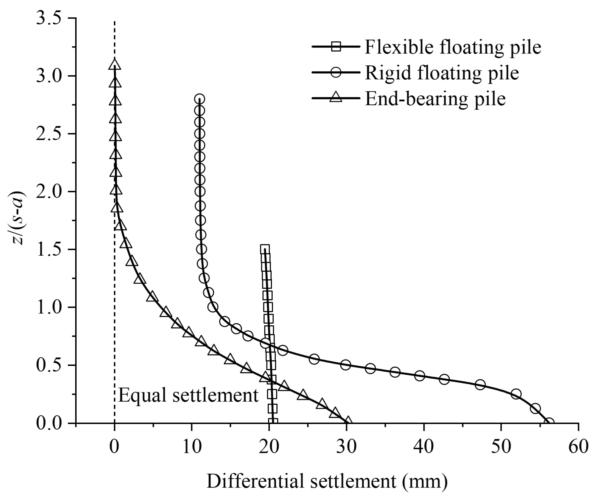
3.2.3. Differential Settlement

Figure 16 shows the variation in differential settlement between the two paths above point A and point B with embankment height normalized by (sa). It has been found that the differential settlement at the embankment surface was 19.5 mm for the flexible floating piles, decreasing to 11.0 mm for the rigid floating piles. For the end-bearing piles, the differential settlement dropped to 0. For rigid floating piles and end-bearing piles, the differential settlement remains constant in the upper of the embankment, and it begins to increase at the depths where the outer of the soil arching reach. For flexible floating piles, the differential settlement on the embankment surface was almost equal to the bottom because the soil arching was insignificant.

4. Conclusions

In this paper, the concept of flexible floating piles and rigid floating piles was proposed. The load-bearing mechanism for floating and end-bearing piles embankments were investigated using the 3D FE analysis. Three typical field cases were adopted to validate the reliability of the modeling approach. The FE analysis results were compared with the field test data, and the errors remained less than 12%. It showed that the modeling was able to simulate well the behavior of the pile-supported embankments with flexible floating piles, rigid floating piles, and end-bearing piles. Moreover, the following conclusions can be drawn:
  • The pile tip resistance of flexible floating piles was the lowest, only 10% of that of end-bearing piles. It means that the flexible floating piles mainly rely on the pile skin friction to carry the load. End-bearing piles mainly rely on pile tip resistance to carry the load, which has 50% as much skin friction as flexible floating piles. In comparison, the load-carrying mechanism of the rigid floating piles was somehow in between.
  • The SRR decreased from 0.90 for flexible floating piles to 0.61 for rigid floating piles and reached 0.44 for end-bearing piles. The K in the embankment employing end-bearing pile was 3.28 at z / ( s a ) = 0.5 , greater than KP, in which the soil arching was fully developed. The K for rigid floating pile-supported embankment was 2.21 at z / ( s a ) = 0.3 , where soil arching might be partially mobilized. At the bottom of the flexible floating pile-supported embankment, the K tended to equal K0, and thus soil arching was insignificant.
  • The differential settlement on the surface of the end-bearing pile-supported embankment was 0 mm because the arching was fully developed. The development of soil arching was initiated once the embankment construction period, and it further developed with the evolution of soil consolidation until a full arching was mobilized. So, it was essential to consider the soil consolidation in the study of the pile-supported embankment.
  • The mechanical behavior and bearing mechanism of pile-supported embankments are significantly different under different pile types. There are two types of floating piles in the practical engineering, and it is unsafe and uneconomical to design follow a uniform guideline. It was economical to choose the flexible floating pile when the thickness of the soft clay was quite high. However, there may be insufficient bearing capacity. Using the end-bearing pile might significantly improve the bearing capacity of the embankment, but it was not cost-effective because of its limited lift compared to the rigid floating pile.

Author Contributions

Conceptualization, methodology and data curation, S.H. and Y.Z.; software, visualization and writing—original draft preparation, S.H.; investigation, validation and resources, Y.W.; writing—review and editing and supervision, Y.Z., X.Z. and X.D.; project administration and funding acquisition, Y.Z. All authors have read and agreed to the published version of the manuscript.

Funding

This research was funded by the National Natural Science Foundation for Excellent Youth Science Fund Project of China (Grant No. 51922029), and the National Natural Science Foundation of China General Program (Grant No. 52178316).

Institutional Review Board Statement

Not applicable.

Informed Consent Statement

Not applicable.

Data Availability Statement

Not applicable.

Conflicts of Interest

The authors declare no conflict of interest.

References

  1. Bouassida, M.; Fattah, M.Y.; Mezni, N. Bearing Capacity of Foundation on Soil Reinforced by Deep Mixing Columns. Geomech. Geoengin. 2022, 17, 309–320. [Google Scholar] [CrossRef]
  2. King, L.; Bouazza, A.; Dubsky, S.; Rowe, R.K.; Gniel, J.; Bui, H.H. Kinematics of soil arching in piled embankments. Géotechnique 2019, 69, 941–958. [Google Scholar] [CrossRef]
  3. Rui, R.; Han, J.; Zhang, L.; Zhai, Y.; Cheng, Z.; Chen, C. Simplified method for estimating vertical stress-settlement responses of piled embankments on soft soils. Comput. Geotech. 2020, 119, 103365. [Google Scholar] [CrossRef]
  4. Phutthananon, C.; Jongpradist, P.; Dias, D.; Jamsawang, P. Numerical study of the deformation performance and failure mechanisms of TDM pile-supported embankments. Transp. Geotech. 2021, 30, 100623. [Google Scholar] [CrossRef]
  5. Pham, T.A.; Dias, D. A simplified model for the analysis of piled embankments considering arching and subsoil consolidation. Geotext. Geomembr. 2022, 50, 408–431. [Google Scholar] [CrossRef]
  6. Wang, K.; Cao, J.; Wang, X.; Ning, Y. Soil Arching of Piled Embankment in Equal Settlement Pattern: A Discrete Element Analysis. Symmetry 2021, 13, 1627. [Google Scholar] [CrossRef]
  7. Cao, W.Z.; Zheng, J.J.; Zhang, J.; Zhang, R.J. Field test of a geogrid-reinforced and floating pile-supported embankment. Geosynth. Int. 2016, 23, 348–361. [Google Scholar] [CrossRef]
  8. Jamsawang, P.; Yoobanpot, N.; Thanasisathit, N.; Voottipruex, P.; Jongpradist, P. Three-dimensional numerical analysis of a DCM column-supported highway embankment. Comput. Geotech. 2016, 72, 42–56. [Google Scholar] [CrossRef]
  9. Ng, K.S.; Tan, S.A. Nonlinear Behaviour of an Embankment on Floating Stone Columns. Geomech. Geoengin. 2014, 10, 30–44. [Google Scholar] [CrossRef]
  10. Liu, K.W.; Rowe, R.K. Numerical modelling of prefabricated vertical drains and surcharge on reinforced floating column-supported embankment behaviour. Geotext. Geomembr. 2015, 43, 493–505. [Google Scholar] [CrossRef]
  11. Liu, H.L.; Ng, C.W.W.; Fei, K. Performance of a Geogrid-Reinforced and Pile-Supported Highway Embankment over Soft Clay: Case Study. J. Geotech. Geoenviron. Eng. 2007, 133, 1483–1493. [Google Scholar] [CrossRef]
  12. Rowe, R.K.; Liu, K.W. Three-dimensional finite element modelling of a full-scale geosynthetic-reinforced, pile-supported embankment. Can. Geotech. J. 2015, 52, 2041–2054. [Google Scholar] [CrossRef]
  13. Han, J.; Gabr, M.A. Numerical analysis of geosynthetic-reinforced and pile-supported earth platforms over soft soil. J. Geotech. Geoenviron. Eng. 2002, 128, 44–53. [Google Scholar] [CrossRef]
  14. Projet National ASIRI. Recommendations for the Design, Construction and Control of Rigid: Inclusion Ground Improvements; Presses des Ponts: Paris, France, 2013. [Google Scholar]
  15. GGS. Recommendations for Design and Analysis of Earth Structures Using Geosynthetic Reinforcements—EBGEO; German Geotechnical Society: Berlin, Germany, 2011. [Google Scholar]
  16. Satibi, S. Numerical Analysis and Design Criteria of Embankments on Floating Piles; Institut für Geotechnik der Universität Stuttgart IGS: Stuttgart, Germany, 2009. [Google Scholar]
  17. van Eekelen, S.J.M.; Bezuijen, A.; van Tol, A.F. Analysis and modification of the British Standard BS8006 for the design of piled embankments. Geotext. Geomembr. 2011, 29, 345–359. [Google Scholar] [CrossRef]
  18. Xu, C.; Song, S.; Han, J. Scaled model tests on influence factors of full geosynthetic-reinforced pile-supported embankments. Geosynth. Int. 2016, 23, 140–153. [Google Scholar] [CrossRef]
  19. Bhasi, A.; Rajagopal, K. Numerical study of basal reinforced embankments supported on floating/end bearing piles considering pile-soil interaction. Geotext. Geomembr. 2015, 43, 524–536. [Google Scholar] [CrossRef]
  20. Pham, T.A. Design and analysis of geosynthetic-reinforced and floating column-supported embankments. Int. J. Geotech. Eng. 2021, 1–17. [Google Scholar] [CrossRef]
  21. Hong, W.P.; Lee, J.; Hong, S. Full-Scale Tests on Embankments Founded on Piled Beams. J. Geotech. Geoenvironmental Eng. 2014, 140, 04014067. [Google Scholar] [CrossRef]
  22. Yadav, S.K.; Ye, G.-L.; Khalid, U.; Fukuda, M. Numerical and centrifugal physical modelling on soft clay improved with floating and fixed sand compaction piles. Comput. Geotech. 2019, 115, 103160. [Google Scholar] [CrossRef]
  23. Wang, A.; Zhang, D. Lateral Response and Failure Mechanisms of Rigid Piles in Soft Soils Under Geosynthetic-Reinforced Embankment. Int. J. Civ. Eng. 2019, 18, 169–184. [Google Scholar] [CrossRef]
  24. Shen, P.; Xu, C.; Han, J. Geosynthetic-reinforced pile-supported embankment: Settlement in different pile conditions. Geosynth. Int. 2020, 27, 315–331. [Google Scholar] [CrossRef]
  25. Zhou, W.-H.; Chen, R.-P.; Zhao, L.-S.; Xu, Z.-Z.; Chen, Y.-M. A semi-analytical method for the analysis of pile-supported embankments. J. Zhejiang Univ. Sci. A 2012, 13, 888–894. [Google Scholar] [CrossRef]
  26. Reshma, B.; Rajagopal, K.; Viswanadham, B.V.S. Centrifuge model studies on the settlement response of geosynthetic piled embankments. Geosynth. Int. 2020, 27, 170–181. [Google Scholar] [CrossRef]
  27. Zhang, H.; Wang, H.; Li, X.; Li, W.; Wu, J.; Lv, C.; Song, X.; Liu, M. An Analysis of Floating Geogrid-Reinforced Pile-Supported Embankments Containing Deep Softened Soil. Arab. J. Sci. Eng. 2021, 46, 10855–10868. [Google Scholar] [CrossRef]
  28. Terzaghi, K.T. Theoretical Soil Mechanics; John Wiley and Sons, Inc.: Hoboken, NJ, USA, 1943. [Google Scholar]
  29. Hewlett, W.J.; Randolph, M.F. Analysis of piled embankments. Ground Eng. 1988, 21, 12–18. [Google Scholar]
  30. Zhuang, Y.; Cui, X. Analysis and modification of the Hewlett and Randolph method. Proc. Inst. Civ. Eng.-Geotech. Eng. 2015, 168, 144–157. [Google Scholar] [CrossRef]
  31. Zhuang, Y.; Wang, K.Y. Finite-element analysis of arching in highway piled embankments subjected to moving vehicle loads. Géotechnique 2018, 68, 857–868. [Google Scholar] [CrossRef]
  32. BSI. BS 8006-1; Code of Practice for Strengthened/Reinforced Soils and Other Fills, Incorporating Corrigendum 1. British Standards Institution: London, UK, 2012.
  33. Pham, T.A.; Wijesuriya, K.; Dias, D. Analytical model for the design of piled embankments considering cohesive soils. Geosynth. Int. 2022, 29, 369–388. [Google Scholar] [CrossRef]
  34. Pham, T.A.; Dias, D. 3D numerical study of the performance of geosynthetic-reinforced and pile-supported embankments. Soils Found. 2021, 61, 1319–1342. [Google Scholar] [CrossRef]
  35. SIMULIA. ABAQUS/CAE User’s Manual; Dassault: Pawtucket, RI, USA, 2020. [Google Scholar]
  36. Smith, M.; Filz, G. Axisymmetric numerical modeling of a unit cell in geosynthetic-reinforced, column-supported embankments. Geosynth. Int. 2007, 14, 13–22. [Google Scholar] [CrossRef]
  37. Ariyarathne, P.; Liyanapathirana, D.S.; Leo, C.J. Comparison of Different Two-Dimensional Idealizations for a Geosynthetic-Reinforced Pile-Supported Embankment. Int. J. Geomech. 2013, 13, 754–768. [Google Scholar] [CrossRef]
  38. Briançon, L.; Simon, B. Performance of Pile-Supported Embankment over Soft Soil: Full-Scale Experiment. J. Geotech. Geoenvironmental Eng. 2012, 138, 551–561. [Google Scholar] [CrossRef]
  39. Zhuang, Y.; Ellis, E.A.; Yu, H.S. Plane strain FE analysis of arching in a piled embankment. Proc. Inst. Civ. Eng.-Ground Improv. 2010, 163, 207–215. [Google Scholar] [CrossRef]
  40. Zhuang, Y.; Ellis, E.; Yu, H.S. Three-dimensional finite-element analysis of arching in a piled embankment. Géotechnique 2012, 62, 1127–1131. [Google Scholar] [CrossRef]
Figure 1. Illustration of the varied types of piles: (a) flexible floating piles; (b) rigid floating piles; (c) end-bearing piles.
Symmetry 14 01981 g001
Figure 2. Finite-element model of flexible floating piles.
Symmetry 14 01981 g002
Figure 3. Subsoil surface settlements versus time.
Symmetry 14 01981 g003
Figure 4. Subsoil settlements with depth.
Symmetry 14 01981 g004
Figure 5. Finite-element model of rigid floating piles.
Symmetry 14 01981 g005
Figure 6. Subsoil and pile settlements from field tests and FEM.
Symmetry 14 01981 g006
Figure 7. Finite-element model of end-bearing piles.
Symmetry 14 01981 g007
Figure 8. Embankment height versus time and settlements versus time measured at pile head and subsoil surface.
Symmetry 14 01981 g008
Figure 9. Vertical stress on top subsoil versus time.
Symmetry 14 01981 g009
Figure 10. Skin friction distributions with the pile length for three piles: (a) flexible floating; (b) rigid floating; (c) end-bearing.
Symmetry 14 01981 g010aSymmetry 14 01981 g010b
Figure 11. Axial force distributions with the pile length for three piles: (a) flexible floating; (b) rigid floating; (c) end-bearing.
Symmetry 14 01981 g011aSymmetry 14 01981 g011b
Figure 12. Vertical stress above the subsoil and pile versus embankment height: (a) flexible floating; (b) rigid floating; (c) end-bearing.
Symmetry 14 01981 g012aSymmetry 14 01981 g012b
Figure 13. Plan view of the finite-element model.
Symmetry 14 01981 g013
Figure 14. Profiles of earth pressure coefficient with height above the base of the embankment: (a) point A (above the subsoil); (b) point B (above the pile).
Symmetry 14 01981 g014
Figure 15. Profiles of max principal stress for end-bearing pile-supported embankment: (a) end of construction; (b) 110 days after completion of construction; (c) end of consolidation.
Symmetry 14 01981 g015
Figure 16. Profiles of differential settlement for three piles.
Symmetry 14 01981 g016
Table 1. Parameters of embankment fill and subsoil.
Soil Layerγ (kN/m3)E (MPa)vλκc′ (kPa)φ′ (°)k (m/d)
Embankment20200.33--130-
Fill20300.33--132-
Soft clay14-0.350.180.041235 × 10−4
Medium stiff clay16-0.150.120.0610252.5 × 10−4
Note: γ, unit weight; E, elastic modulus; v, Poisson’s ratio; λ, logarithmic plastic bulk modulus; κ, logarithmic bulk modulus; c′, effective cohesion; φ′, effective friction angle; k, permeability coefficient.
Table 2. Detailed parameters of the soil layers and piles.
Materialγ (kN/m3)E (MPa)φ′ (°)vλκe1K × 10−4 (m/d)
Pile24.020,000-0.20----
Embankment18.520300.30----
Gravel18.520400.30---
Fill18.57280.30----
Silty clay20.0--0.350.060.0120.878.64
Soft silty clay17.0--0.400.150.0301.794.32
Medium silty clay20.5--0.350.050.0101.104.32
Sandy silt20.0--0.350.030.0050.2843.2
Note: e1, void ratio at unit pressure.
Table 3. Parameters of each soil layer.
Soil LayerMaterialγ (kN/m3)φ′ (°)e0vλκk (m/s)
S1Clayey backfill20.030.60.750.350.0920.014-
S2Clayey backfill20.030.61.300.360.1910.029-
S3Beige clay14.030.62.000.370.3080.0468.8 × 10−8
S4Clayey gray sand19.030.60.700.350.0740.0111.0 × 10−6
S5Lightly plastic clay20.527.00.900.320.1160.0176.1 × 10−7
S6Sandy clay20.527.00.800.320.0880.0136.1 × 10−7
S7Gravel21.034.00.750.310.0270.0046.6 × 10−5
Note: e0, initial void ratio.
Table 4. Properties of gravel cushion, embankment fill and piles.
Materialγ (kN/m3)E (MPa)vc′ (kPa)φ′ (°)
Embankment18.5200.31030
Gravel (cushion)20700.36036
Pile2420,0000.218,000-
Publisher’s Note: MDPI stays neutral with regard to jurisdictional claims in published maps and institutional affiliations.

