Article

Stability Evaluation Method of Hole Wall for Bored Pile under Blasting Impact

1
School of Civil and Transportation Engineering, Ningbo University of Technology, Ningbo 315211, China
2
Engineering Research Center of Industrial Construction in Civil Engineering of Zhejiang, Ningbo University of Technology, Ningbo 315211, China
*
Authors to whom correspondence should be addressed.
Symmetry 2022, 14(1), 79; https://doi.org/10.3390/sym14010079
Submission received: 4 December 2021 / Revised: 23 December 2021 / Accepted: 25 December 2021 / Published: 5 January 2022
(This article belongs to the Special Issue Recent Advances in Mechanical and Biomedical Mechanical Engineering)

Abstract

:
Blasting impact load may be encountered during the construction of some pile foundation projects. Due to the effect of blasting impact, hole collapse can easily occur in the hole-forming stage of pile foundation construction. In order to prevent hole collapse, it is very necessary to evaluate the stability of a pile hole wall before pile foundation construction. The calculation of hole collapse can usually be attributed to an axisymmetric circular hole stress concentration problem. However, the existing collapse failure theory of pile hole hardly considers the effect of blasting impact load. In view of this, this paper proposes the stability evaluation method of a pile hole wall under blasting impact. Compared with the existing collapse failure theory, the proposed method fully considers the effect of blasting impact stress. Using Mohr–Coulomb strength theory and symmetry analysis, the strength condition of collapse failure is established in this work for accurate evaluation of the stability of a hole wall. The proposed stability evaluation method is demonstrated by a pile foundation construction project of a bridge. Moreover, a shaking table test on the pile hole model was performed to verify the proposed method by experimental data. The results indicate the effectiveness and usability of the proposed method. The proposed method provides a feasible way for the stability analysis of a pile hole wall under blasting impact.

1. Introduction

Bored pile is a common foundation form in building and bridge structures [1,2,3,4,5,6]. Its main construction process includes two stages: drilling rig excavation to form the pile hole and pouring concrete to form the pile foundation. In the hole-forming stage of construction, hole collapse can easily occur due to insufficient soil bearing capacity or the action of an external load [7,8,9,10,11,12]. Therefore, it is very necessary to evaluate the stability of a pile hole wall before pile foundation construction. Generally, the calculation of hole collapse can usually be attributed to an axisymmetric circular hole stress concentration problem. Bradley [13] analyzed the borehole wall collapse and borehole wall failure caused by stress using the Drucker Prager failure criterion. In their simplified soil layer model, the tensile strength is not considered and the failure effect of the stratum is analyzed according to this model. Using a porous elastic medium model, Roegiers [14] considered more factors in the research method of hole wall stability. Li [15] studied the stability of a super-long bored pile by considering the resistance of soil on the side of the pile. Using Mohr–Coulomb ideal elastic–plastic theory, Shi [16] studied the shrinkage and subsequent problems of lateral soil during drilling construction. The functional relationship between the gravity of stabilizing fluid and the stress in the soil around the pile was obtained. Hu [17] analyzed the stress around the hole during the hole-forming process of cast-in-place pile. The minimum and maximum depth of stabilizing fluid in the pile hole was obtained. By regarding the soil layer as a viscoelastic body, Li [18] derived the functional relationship between the horizontal stress, displacement, and deformation of the hole wall and time. Wang [19] found that the necking of the pile or the collapse of the hole wall will occur if the expansion of the plastic zone is not controlled. Bassey [20] suggested that the instability of a borehole wall is mainly a problem of borehole wall cracking and borehole wall collapse. Yin [21] used Mohr–Coulomb strength theory and limit analysis theory to simplify the pile side soil into two models of static strength and dynamic strength. It has been shown that saturated sand will not liquefy the pile side soil under the construction condition. According to the basic theory of elastic and plastic mechanics, Zhang [22] established an evaluation model of the stability of the hole wall and the instability criterion of the borehole wall. Using numerical analysis, Wang [23] suggested that the key influencing factors that affect the stabilization of a bored-pile hole wall are the aperture, hole depth, specific gravity of slurry, protective barrel depth, and hole-forming time. Tang [24] used finite element analysis software to build a drilling model to simulate a rock soil mass deformation trend and find the deformation and instability mechanism. Gao et al. [25] discussed the effect of a ventilated open structure on the temperature at the pile–soil interface and the bearing capacity of bored piles based on monitoring the results of bored piles. Mattos and Marin [26] carried out parametric analyses of bored-pile wall stability by using the expanded reliability-based design approach and finite element analysis. Their results indicate that cohesion and groundwater level are factors that significantly affect bored-pile wall stability. Yang [27] discussed the effects of borehole diameter, borehole depth, and mud bulk density on borehole wall collapse under static loads. He proposed a theoretical evaluation model of hole wall collapse by considering the weight of different influencing factors. The method has been successfully verified in a specific pile foundation project in Guangdong Province of China. Considering the effect of intermediate principle stress, Gong and Zhao [28] deduced the solutions of critical mud density and initial plastic depths of borehole for collapse and the contraction problem on the hole of bored pile. The effects of the internal friction angle, the size of holes, and unified strength parameter of the solutions were analyzed by an example. Xie [29] used unified strength theory to analyze the stability of a pile hole wall. The closed-form solutions for vertical borehole and calculation process for deviated borehole were achieved from the unified strength theory.
In summary, there have been many studies on the collapse of a pile hole wall under static load. The strength theory of collapse failure under static load has been established and successfully applied in specific projects. However, the existing collapse failure theory of pile hole hardly considers the effect of blasting impact load. Blasting impact load may be encountered during the construction of some pile foundation projects. Due to the effect of blasting impact, hole collapse is more easily occurs in the hole-forming stage of pile foundation construction. In view of this, this research proposed a stability evaluation method of pile hole wall under blasting impact. Compared with the existing collapse failure theory, the proposed method fully considers the effect of blasting impact stress. Using Mohr–Coulomb strength theory and symmetry analysis, the strength condition of collapse failure was established in this work for accurate evaluation of the stability of a hole wall. The proposed stability evaluation method is demonstrated by a pile foundation construction project of a bridge. The calculation results indicate the effectiveness and usability of the proposed method. The proposed method provides a feasible way for a stability analysis of a pile hole wall under blasting impact.

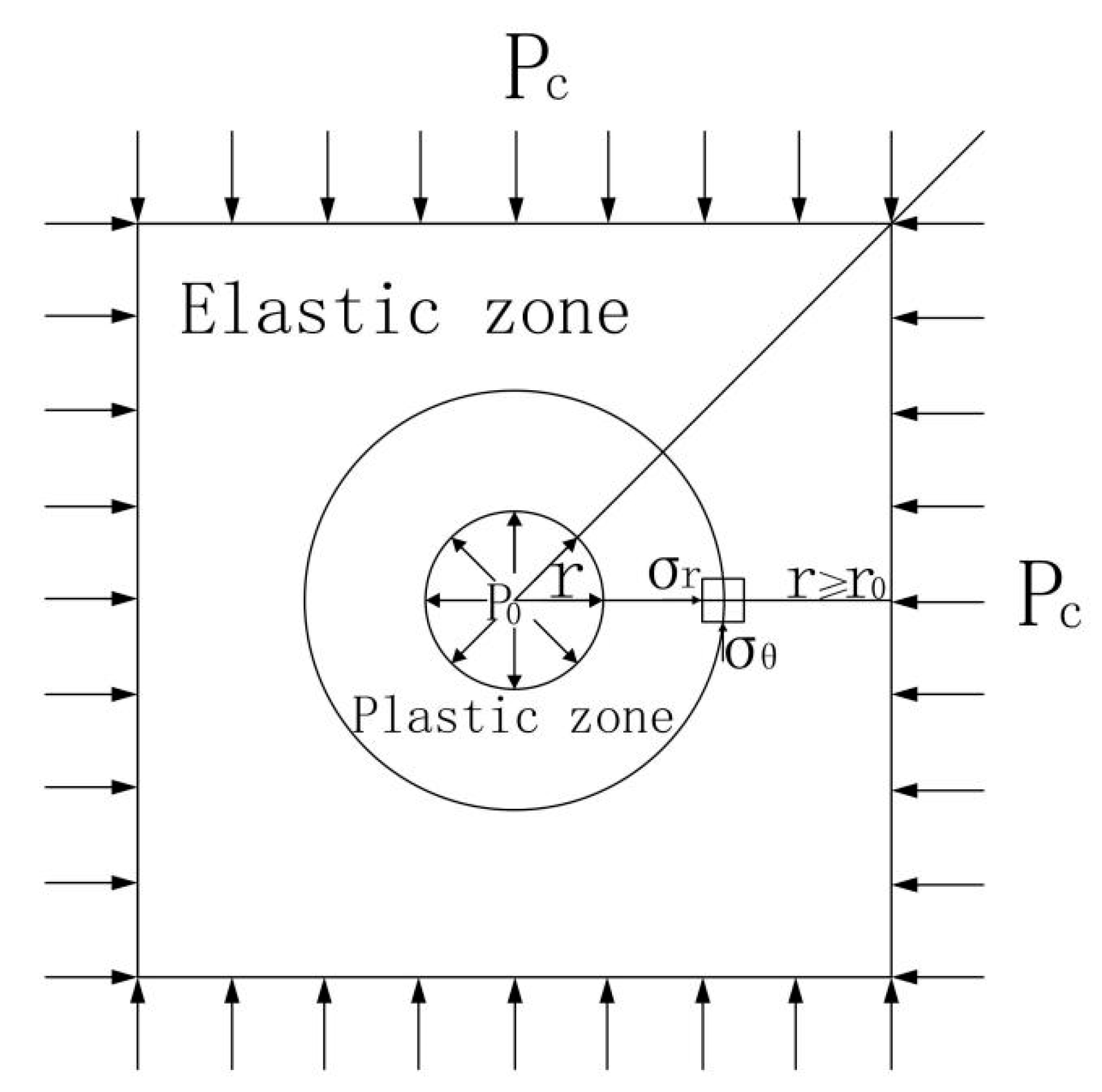
2. Stability Analysis of Hole Wall under Static Load

The rock and soil mass in the deep stratum is affected by the pressure of the overlying stratum. Before the bored pile is formed, the soil layer on the hole wall is in an initial mechanical equilibrium state. During the bored pile construction, the lateral pressure of the hole wall is relieved since the soil is brought out by the drilling rig. The hole wall loses the lateral support of the original soil. This leads to the redistribution of soil stress around the hole, destroys the original soil structure, and reduces the strength of the soil. As a result, the hole wall may collapse due to insufficient strength. This is also called hole wall instability failure. In this section, the stability analysis algorithm in Reference [22] of a hole wall for bored pile under static load is briefly reviewed. To this end, several assumptions should first be made for carrying out the stress analysis of the hole wall. The first assumption is that the ratio of pile length to hole diameter is very large. The second assumption is that the soil is a homogeneous and isotropic ideal elastic–plastic material. The third one is that the soil still contains linear deformation outside the plastic zone. The last one is that the hole wall can be determined to be damaged when the stress at any point of the hole wall meets the failure criterion. Without less generality, a pile hole as shown in Figure 1 is used to illustrate the stability analysis process under static load. In Figure 1, ρ 0 is the density of drilling mud; ρ j ,   γ j ,   h j ( j = 1 ,   2 ,   3 ) are the density, unit weight, and thickness of the j th soil layer, respectively. q is the construction surface load, h is the height of steel casing above the ground, h 0 is the height of the mud level drop caused by the lifting of the drilling rig, and z is the depth of hole wall to be discussed.
According to the elastic–plastic theory, the stress analysis of hole wall at a certain depth can be regarded as a problem of stress concentration of a circular hole in an infinite plane, as shown in Figure 2.
Using polar coordinates, the soil stress balance equation at the hole wall can be expressed as
d σ r d r + σ r σ θ r = 0
where σ r is the radial compressive stress, σ θ is the circumferential compressive pressure, and r is the radius of the circle. Obviously, this is an axisymmetric elastic problem. The boundary condition equations are
σ r = p 0 ,   r = r 0
σ r = p c ,   r
where r 0 is the radius of the pile hole, p 0 is the pressure generated by drilling mud, and p c is the initial geostress. When the drilling rig is working, the pressure p 0 can be calculated by
p 0 = ρ 0 g ( h + z h 0 ) + ( π / 2 + z / r 0 ) f m f c
where ρ 0 is the density of drilling mud, g is the gravitational acceleration, h is the height of steel casing above the ground, z is the depth of hole, f m is the shear strength of the gelled mud, and f c is the suction force generated by lifting the drilling rig.
According to the theory of elasticity, the stress calculation formulas in three directions at a point on the hole wall with depth z are as follows:
σ z = j = 1 i 1 γ j h j + γ i ( z j = 1 i 1 h j ) + q
σ r = p 0
σ θ = 2 k i σ z p 0
where σ z is the vertical stress, and k i is the lateral pressure coefficient, which can be calculated according to the Poisson’s ratio μ i as
k i = μ i 1 μ i
Generally, the lateral pressure coefficient k i of common clay is about 0.7. Thus, the most common case under a certain depth is σ θ σ z σ r . As a result, the three principal stresses σ 1 , σ 2 , and σ 3 can be taken as
σ 1 = 2 k i σ z p 0
σ 2 = j = 1 i 1 γ j h j + γ i ( z j = 1 i 1 h j ) + q
σ 3 = p 0
According to Mohr–Coulomb strength theory (shown in Figure 3), the strength condition of collapse failure can be expressed as
σ 1 σ 3 2 σ 1 + σ 3 2 sin φ i c i cos φ i 0
where ϕ i is the interior friction angle, and c i is the cohesive force of the i -th soil layer. Substituting Equations (4), (8), (9), and (11) into (12), the strength condition of collapse failure at a point on the hole wall with depth z can be obtained as:
σ z [ σ ]
[ σ ] = ρ 0 g ( h + z h 0 ) f c + ( π / 2 + z / r 0 ) f m + c i cos ϕ i k i ( 1 sin ϕ i )
where σ z can be seen as the stress that causes hole collapse, and [ σ ] can be seen as the allowable stress.

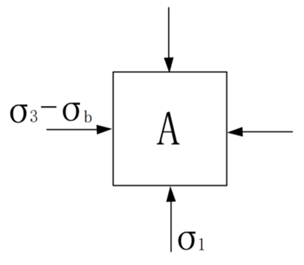
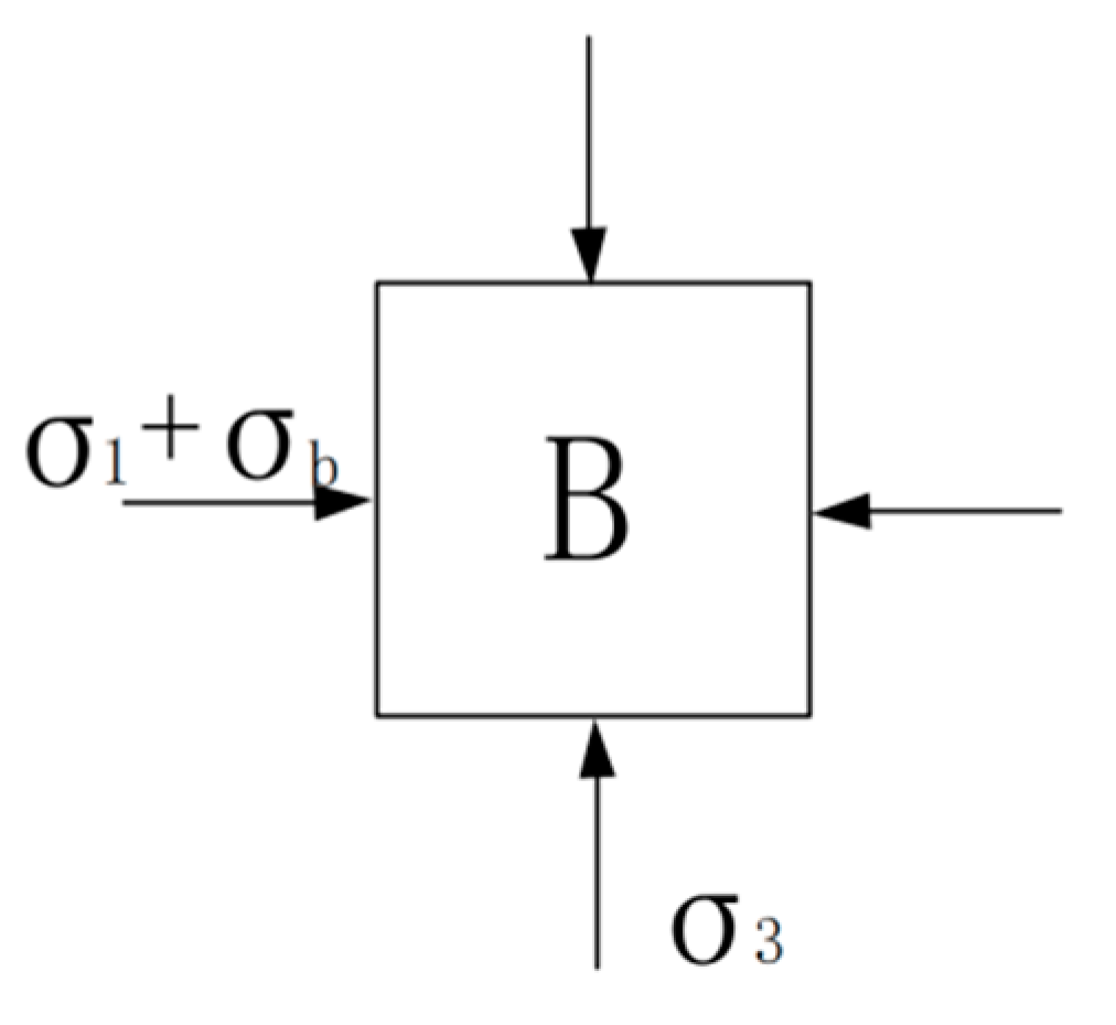
3. Stability Analysis of Hole Wall under Blasting Impact

For some engineering projects, blasting works and pile foundation works may be carried out at the same time. As stated before, the evaluation method of hole wall stability under blasting impact has not been reported. In view of this, this paper presents an analytical method for the evaluation of hole wall stability under blasting impact. Apparently, blasting impact will produce vibration velocity, acceleration, displacement, and stress in soil. Blasting stress makes the hole wall more prone to collapse failure. In References [30,31,32,33,34], the relationship between soil stress and impact velocity is discussed. If the vibration velocity V i of the i -th soil layer is measured, the blasting stress σ b in the soil can be calculated by means of dimensional analysis as [34]
σ b = ρ i C ρ i V i
where C ρ i is the converted longitudinal wave velocity of the i -th soil layer, and ρ i is the density of the i th soil layer. Under the action of blasting stress, there may be four points on the hole wall that are most prone to collapse, as shown in Figure 4.
Due to symmetry, only two points “A” and “B” in Figure 4 are taken for stress analysis. For point “A”, the stresses in the unit body after considering blasting stress is shown in Figure 5.
From Figure 5, σ 1 of point “A” is unchanged, and σ 3 of point “A” has changed to be
σ 3 A = σ 3 σ b
By replacing σ 3 with σ 3 A , the strength condition of collapse failure for point “A” after considering blasting stress can be derived using Equation (12) as
σ ¯ [ σ ] ,   σ ¯ = σ z + ( 1 + sin φ i ) 2 k i ( 1 sin φ i ) σ b
The detailed derivation process of Equation (17) can be found in Appendix A. For point “B”, the stresses in the unit body after considering blasting stress are shown in Figure 6.
From Figure 6, σ 3 of point “B” is unchanged, and σ 1 of point “B” has changed to be
σ 1 B = σ 1 + σ b
By replacing σ 1 with σ 1 B , the strength condition of collapse failure for point “B” after considering blasting stress can also be derived using Equation (12) as:
σ z + 1 2 k i σ b [ σ ]
Compared Equations (17) and (19), it can be concluded that point “A” is more prone to collapse than point “B”. Therefore, Equation (17) can be finally determined as the strength condition of collapse failure for pile hole wall under blasting impact.

4. Case Study

The proposed stability evaluation method is demonstrated by a pile foundation construction project of a planned bridge in Ningbo, China. According to the geological exploration report of this project, the soil surrounding the pile hole can be divided into ten layers from top to bottom, as shown in Figure 7. The physical parameters of each soil layer at the pile hole location are listed in Table 1. These physical parameters are obtained through geological exploration and testing at the project site. The blasting operation of nearby mountains will be carried out during the construction of the bored cast-in-place pile. The diameter and length of the pile are 2.8 m and 65 m, respectively. The penetration depth of steel casing used in pile foundation construction is 25 m. For construction safety, it is very necessary to evaluate in advance the stability of the pile hole wall under blasting impact.
The vibration velocity near the pile hole caused by blasting impact is V = 2 cm/s. The specific values of other parameters in the pile foundation project are: ρ 0 = 12 kN/m3, q = 10 kPa, h = 2 m, h 0 = 1 m, and f c = 35 kPa.
Using the proposed method, the calculation results for stability evaluation of a hole wall under blasting impact are listed in Table 2.
Comparing column 3 with column 4 in Table 2, one can find that the calculation results of most soil layers meet the requirements of Equation (17), i.e., σ ¯ [ σ ] , except for the 1, 2, and 4 soil layers. This means that the hole wall in these soil layers that do not meet Equation (17) may be prone to collapse under blasting impact. However, the 1 and 2 soil layers will not collapse due to the protection of the steel casing with 25 m penetration. Therefore, only the soil of the fourth layer below the steel casing may collapse due to blasting impact. In view of this, measures shall be taken in advance during the construction of the pile foundation to prevent hole collapse. It is obvious that reducing the impact velocity is an effective measure for preventing hole collapse. Using Equation (17), the safe impact velocity for this case can be calculated inversely as 1.4 cm/s. According to this safe impact velocity, the explosive quantity used in mountain blasting can be reduced accordingly to prevent hole collapse in the pile foundation construction.

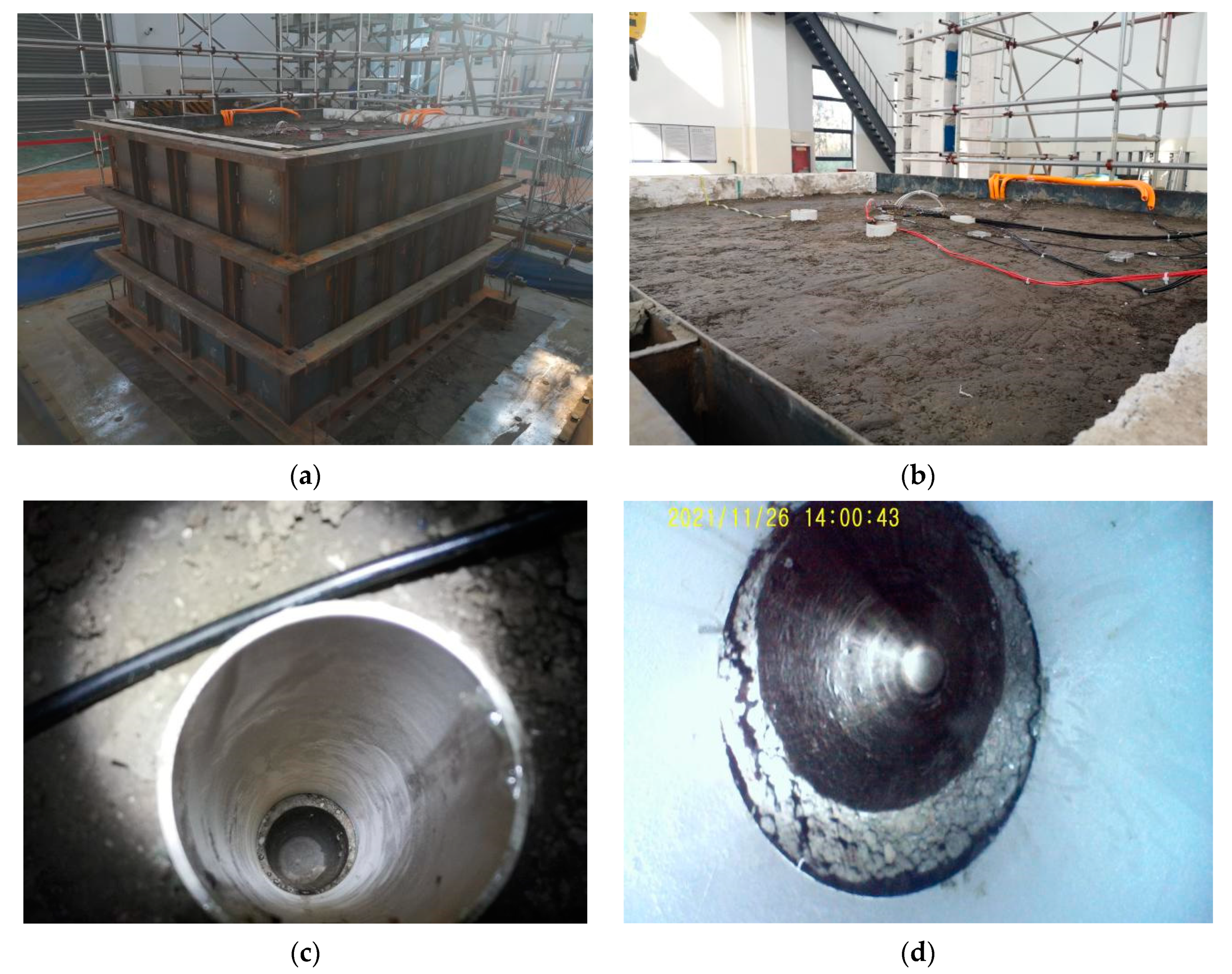
5. Experimental Verification

As shown in Figure 8, a shaking table test on the pile hole model was performed to verify the proposed stability evaluation method. The steel model box is fixedly connected with the shaking table. The impact load is simulated by the vibration of the shaking table. The peak velocity of vibration is measured by embedding several acceleration sensors in the soil. The length, width, and height of the steel model box are 2.4 m, 1.9 m, and 1.5 m. The height of soil in the model box is 1.2 m. The diameter and length of the pile hole in the model box are 70 mm and 1.2 m, respectively. The diameter and penetration depth of PVC tube are 90 mm and 0.625 m, respectively. According to the basic mechanical properties test, the physical parameters of the soil in the model box are unit weight γ i = 19.6 kN/m3, cohesion force c i = 15.3 kPa, and interior friction angle ϕ i = 14.7°.
Using the proposed method, the estimated results for stability analysis of the hole wall under impact velocities with V = 2.5 cm/s and V = 3 cm/s are listed in Table 3 and Table 4, respectively.
From Table 3 and Table 4, the estimated results obtained by the proposed method indicate that the hole wall may collapse under impact velocity of about 3 cm/s. Furthermore, the safe impact velocity for this experimental model can be calculated inversely by using Equation (17) as 2.73 cm/s. Based on the experimental results on the shaking table, one of the pile holes collapsed when the impact velocity was about 2.9 cm/s. A comparison of hole wall photos before and after damage is shown in Figure 9. It can be seen from Figure 9 that the hole wall is smooth before collapse. After collapse, the hole wall is very uneven due to soil falling off. Comparing 2.73 cm/s with 2.9 cm/s, the impact velocity predicted by the proposed approach is close to that obtained by the experiment. In comparison, the impact velocity predicted by the theory is safe, which is more conducive to practical engineering application. It has been shown that the proposed method is reasonable and effective for the stability evaluation of a pile hole wall under impact load.

6. Conclusions

The stability evaluation method was studied in this work for a hole wall of bored pile under blasting impact. Compared with the existing collapse failure theory, the proposed method fully considers the effect of blasting impact stress. Using Mohr–Coulomb strength theory and symmetry analysis, the strength condition of collapse failure was established in this work for accurate evaluation of the stability of a hole wall. The proposed stability evaluation method was demonstrated by a pile foundation construction project for a bridge. The calculation results indicate the effectiveness and usability of the proposed method. Due to the complexities of the actual soil layers, it is impossible to accurately simulate the stress and deformation of the actual soil layer even if the finite element method is used. In view of this, the stress field disturbances at the boundary of the layers were not considered in the current work. This simplified operation will make the analysis and calculation of hole wall stability simple and feasible. Thus, the proposed method can serve as a convenient and fast evaluation method for hole wall stability under blasting impact in practice. The calculation results obtained by the method can be used as a reference for pile foundation construction practice to successfully avoid hole collapse. In summary, the proposed method has the following advantages. (1) The application range is wide. The proposed method can be applied to the stability analysis of a hole wall under blasting impact or other vibration loads. (2) The operation process is simple. The evaluation can be carried out by using this method as long as the peak value of vibration velocity at the hole wall is measured. (3) The computation cost is very small, so it can carry out rapid evaluation. The proposed method provides a feasible way for the stability analysis of a pile hole wall under blasting impact. It should be pointed out that the proposed method is planned to be used in a specific bridge pile foundation project in Ningbo city of China in the next two years. Relevant reports on the specific engineering application of this method will be presented in subsequent papers.

Author Contributions

Conceptualization, Q.Y. and Z.Z.; methodology, Q.Y.; software, Z.B.; validation, Z.B. and Y.S.; data curation, X.P.; writing—original draft preparation, Q.Y. and Z.B.; writing—review and editing, Q.Y. and Z.Z. All authors have read and agreed to the published version of the manuscript.

Funding

This work was supported by the Ningbo Natural Science Foundation Project (202003N4169), Natural Science Foundation of China (52008215), the Natural Science Foundation of Zhejiang Province, China (LQ20E080013), and the major special science and technology project (2019B10076) of “Ningbo Science and Technology Innovation 2025”.

Institutional Review Board Statement

Not applicable.

Informed Consent Statement

Not applicable.

Data Availability Statement

Not applicable.

Conflicts of Interest

The authors declare that there are no conflict of interest.

Appendix A

The detailed derivation process of Equation (17) is shown as follows:
Using Equations (12) and (16), the new strength condition of collapse failure after considering blasting stress can be established by replacing σ 3 with σ 3 A as
σ 1 ( σ 3 σ b ) 2 σ 1 + ( σ 3 σ b ) 2 sin φ i c i cos φ i 0
Substituting Equations (9) and (11) into (A1), one has
2 k i σ z 2 p 0 + σ b 2 2 k i σ z p 0 + p 0 σ b 2 sin φ i c i cos φ i 0
Equation (A2) can be further simplified as
k i ( 1 sin φ i ) σ z + 1 + sin φ i 2 σ b p 0 + c i cos φ i
From Equation (A3), one has
σ z + 1 + sin φ i 2 k i ( 1 sin φ i ) σ b p 0 + c i cos φ i k i ( 1 sin φ i )
Substituting Equation (4) into (A4), Equation (17) can be obtained as
σ ¯ [ σ ]
where
σ ¯ = σ z + ( 1 + sin φ i ) 2 k i ( 1 sin φ i ) σ b
[ σ ] = p 0 + c i cos φ i k i ( 1 sin φ i ) = ρ 0 g ( h + z h 0 ) f c + ( π / 2 + z / r 0 ) f m + c i cos ϕ i k i ( 1 sin ϕ i )

References

  1. Tian, Y.; Zhou, Z.; Dong, Y.; Wang, K.; Feng, H. Study on the value of side friction of bored pile in loess area considering the influence of length diameter ratio. Arab. J. Geosci. 2021, 14, 2067. [Google Scholar] [CrossRef]
  2. Moayedi, H.; Hayati, S. Applicability of a CPT-based neural network solution in predicting load-settlement responses of bored pile. Int. J. Geomech. 2018, 18, 06018009. [Google Scholar] [CrossRef]
  3. Zhou, Z.; Zhang, Z.; Chen, C.; Xu, F.; Xu, T.; Zhu, L.; Liu, T. Application of load transfer method for bored pile in loess area. Eur. J. Environ. Civ. Eng. 2021, 1, 1–19. [Google Scholar] [CrossRef]
  4. Zhang, Q.-Q.; Feng, R.-F.; Yu, Y.-L.; Liu, S.-W.; Qian, J.-G. Simplified approach for prediction of nonlinear response of bored pile embedded in sand. Soils Found. 2019, 59, 1562–1578. [Google Scholar] [CrossRef]
  5. Ng, C.W.W.; Zhang, L.; Nip, D.C.N. Response of laterally loaded large-diameter bored pile groups. J. Geotech. Geoenviron. Eng. 2001, 127, 658–669. [Google Scholar] [CrossRef]
  6. Gao, L.; Han, C.; Xu, Z.; Jin, Y.; Yan, J. Experimental Study on Deformation Monitoring of Bored Pile Based on BOTDR. Appl. Sci. 2019, 9, 2435. [Google Scholar] [CrossRef] [Green Version]
  7. Wang, Y.; Zhang, G.; Hu, Q. Analysis of stability of bored pile holewall. Chin. J. Rock Mech. Eng. 2011, 30, 3281–3287. [Google Scholar]
  8. Wu, Y.H.; Zhou, Z.; Chen, W.Q.; Liu, S.Y.; Zhang, B.C.; Huang, H.F. Research on Construction Technology of cast-in-situ bored pile under Complex Geological Conditions[C]//IOP Conference Series: Earth and Environmental Science. IOP Publ. 2020, 510, 052089. [Google Scholar]
  9. Xiulei, D.Y.Y. Bored Pile of Bridge-Prevention and Solution of Hole Collapse. For. Sci. Technol. Inf. 2002, 4, 15–19. [Google Scholar]
  10. Duan, Z.D.; Duan, Y.P.; Yan, P.W. Influencing factors Analysis of Stability of Hole wall of bored Pile in Seasonal Frozen Ground in the West of China. In Applied Mechanics and Materials; Trans Tech Publications Ltd.: Uetikon-Zuerich, Switzerland, 2013; Volume 256, pp. 441–444. [Google Scholar]
  11. Marlow, P.; Webber, S.; Mikula, P.A.; Lee, M. Bored reinforced piles for raisebore support: Four case studies, and guidelines developed from lessons learnt. Min. Technol. 2013, 122, 159–165. [Google Scholar] [CrossRef]
  12. Yin, M.Z. A Pile Foundation problem: Collapse of soil in pile bore holes. In Applied Mechanics and Materials; Trans Tech Publications Ltd.: Uetikon-Zuerich, Switzerland, 2015; Volume 744, pp. 413–416. [Google Scholar]
  13. Bradley, W.B. Mathematical Stress cloud, Strss cloud can Predict borehole failure. Oil Gas J. 1979, 79, 92–102. [Google Scholar]
  14. Roegiers, J.C. Well Modeling: An overview. Oil Gas Sci. Technol. 2002, 57, 569–577. [Google Scholar] [CrossRef]
  15. Li, J.P.; Chen, M.; Liang, F.Y. Analysis of Stability of Super-Long Bored Pile Considering Resistance of Soil on the Side of Pile. In Deep Foundations and Geotechnical In Situ Testing; Geotechnical Special Publication: Shanghai, China, 2010; pp. 161–168. [Google Scholar]
  16. Shi, C. Stability Analysis of Bored Pile Hole Wall and Application of Post Grouting; Southeast University: Nanjing, China, 2006. (In Chinese) [Google Scholar]
  17. Hu, X.; Li, Z. Mechanical analysis of bored cast-in-place pile of bridge in thick alluvial overburden area. J. Wuhan Sci. Technol. Univ. Traffic Sci. Eng. Ed. 2007, 31, 734–737. [Google Scholar]
  18. Li, S.; Huang, A.; Lu, J.; Wang, J. Study on pore diameter change and unloading effect mechanism of bored cast-in-place pile. Build. Sci. 2010, 26, 76–80. [Google Scholar]
  19. Wang, Z. Study on influencing factors of hole wall stability of bored pile. Highw. Traffic Technol. 2011, 28, 86–90. [Google Scholar]
  20. Bassey, A.; Dosunmu, A.; Buduka, S.; Alabi, T. Wellbore Strengthening and bore hole stability. In Proceedings of the Society of Petroleum Engineers Nigeria Annual International Conference and Exhibition, Abuja, Nigeria, 1–3 August 2011; pp. 189–195. [Google Scholar]
  21. Yin, S. Theoretical Study on Soil Stability of Cast-in-Place Pile Hole under Vibration of Drill Pipe Less Drilling Tool; Harbin Institute of Technology: Harbin, China, 2012. (In Chinese) [Google Scholar]
  22. Zhang, J.X. Research on the Appraisal and Reinforcement Method of the Hole-Wall Stability of Large Aperture Bored Piles in Complex and Rich Water Subsoil; Qingdao Technological University: Qingdao, China, 2015. (In Chinese) [Google Scholar]
  23. Wang, Z. Research on the Factors Affecting the Stabilization of Bored Pile Hole Wall. J. Highw. Transp. Res. Dev. 2012, 6, 72–77. [Google Scholar] [CrossRef]
  24. Tang, S.L.; Wang, B.; Meng, Z.H.; Zhang, J.H. Stability Analysis of Bored Pile Rotary Drilling Based on Finite Element Method. Coal Technol. 2016, 6, 20–25. [Google Scholar]
  25. Gao, Q.; Wen, Z.; Brouchkov, A.; Zhang, M.; Feng, W.; Zhirkov, A. Effect of a ventilated open structure on the stability of bored piles in permafrost regions of the Tibetan Plateau. Cold Reg. Sci. Technol. 2020, 178, 103116. [Google Scholar] [CrossRef]
  26. Mattos, Á.J.; Marin, R.J. Reliability Analysis of Bored-pile Wall Stability Considering Parameter Uncertainties. Tecnológicas 2020, 23, 159–175. [Google Scholar] [CrossRef]
  27. Yang, D.B. Research on the Analysis of the Collapse Influence Factors and Stability Evaluation of the Hole-Wall of Large Aperture Bored Piles; Qingdao Technological University: Qingdao, China, 2014. [Google Scholar]
  28. Gong, H.; Zhao, C. Stability analysis of borehole based on unified strength theory. J. Shenyang Jianzhu Univ. 2011, 27, 237–241+271. [Google Scholar]
  29. Xie, X. Borehole Stability Analysis Based on the Unified Strength Theory; Zhejiang University: Hangzhou, China, 2013. [Google Scholar]
  30. Ghadiri, H.; Payne, D. Raindrop impact stress and the breakdown of soil crumbs. J. Soil Sci. 1977, 28, 247–258. [Google Scholar] [CrossRef]
  31. Mayne, P.W.; Jones, J.S., Jr. Impact stresses during dynamic compaction. J. Geotech. Eng. 1983, 109, 1342–1346. [Google Scholar] [CrossRef]
  32. Kawahara, S.; Muro, T. Effects of dry density and thickness of sandy soil on impact response due to rockfall. J. Terramech. 2006, 43, 329–340. [Google Scholar] [CrossRef]
  33. Chow, S.H.; O’loughlin, C.D.; Randolph, M.F. Soil strength estimation and pore pressure dissipation for free-fall piezocone in soft clay. Géotechnique 2014, 64, 817–827. [Google Scholar] [CrossRef]
  34. Chen, L.J. Distribution law of damage zone in bench rock mass under mining blasting. Blasting 2020, 37, 85–89. [Google Scholar]
Figure 1. A pile hole under static load.
Symmetry 14 00079 g001
Figure 2. Stress concentration of a circular hole in an infinite plane.
Symmetry 14 00079 g002
Figure 3. Mohr–Coulomb failure criterion.
Symmetry 14 00079 g003
Figure 4. Stress analysis of hole wall under blasting impact.
Symmetry 14 00079 g004
Figure 5. The stresses in the unit body “A”.
Symmetry 14 00079 g005
Figure 6. The stresses in the unit body “B”.
Symmetry 14 00079 g006
Figure 7. Pile foundation of a bridge structure.
Symmetry 14 00079 g007
Figure 8. Shaking table test of the pile hole model. (a) Steel model box on the shaking table. (b) Plane figure of pile holes. (c) The intact hole (the upper part is PVC tube). (d) Photo of the intact hole wall of the lower part.
Symmetry 14 00079 g008
Figure 9. Comparison of hole wall before and after damage.
Symmetry 14 00079 g009
Table 1. Physical parameters of each soil layer at the pile hole location.
Soil Layer NumberLayer Thickness (m)Unit Weight
γ i   ( kN / m 3 )
Cohesion   Force   c i   ( kPa ) Interior   Friction   Angle   ϕ i Compression Modulus (MPa)Poisson’s Ratio
11.016.58.510.82.500.47
217.017.6510.7513.453.160.42
34.017.911.58.73.420.39
4917.117.46.653.030.42
51217.618.315.64.190.38
61.018.644.37.35.820.33
7419.134.914.56.530.36
8522.55.05222.950.3
9225.07.05725.720.25
101528.09.05935.600.22
Table 2. Calculation results for stability evaluation of a hole wall under blasting impact.
Soil Layer NumberLayer Thickness (m) σ ¯   ( kPa ) [ σ ]   ( kPa )
11.037.9−12.0
217.0206.5182.6
34.0390.5420.8
49496.5487.7
512698.6978.9
61.0809.71262.8
74863.41334.7
851258.76450.9
921601.211693.1
10152050.518161.0
Table 3. Estimated results for hole wall stability when impact velocity V = 2.5 cm/s.
LocationDepth (m) σ ¯   ( kPa ) [ σ ]   ( kPa ) Comparison
Bottom of PVC tube0.62518.8627.39 σ ¯ < [ σ ]
Soil layer under PVC tube0.82526.5127.39 σ ¯ < [ σ ]
Table 4. Estimated results for hole wall stability when impact velocity V = 3 cm/s.
LocationDepth (m) σ ¯   ( kPa ) [ σ ]   ( kPa ) Comparison
Bottom of PVC tube0.62520.8327.39 σ ¯ < [ σ ]
Soil layer under PVC tube0.82528.4827.39 σ ¯ > [ σ ]
Publisher’s Note: MDPI stays neutral with regard to jurisdictional claims in published maps and institutional affiliations.

