1. Introduction
The HIBEAM/NNBAR program [
1] is a proposed two-stage experiment at the European Spallation Source (ESS) designed to search for neutrons converting, or oscillating, into antineutrons (
) and/or sterile neutrons (
). Such an observation would indicate baryon number violation, a fundamental Sakharov condition for baryogenesis [
2], or act as a sign of a potential dark sector [
3]. In addition to shedding light on the baryon asymmetry of the universe [
4,
5,
6,
7], neutron conversions would provide the first falsification outside of the neutrino sector of the Standard Model (SM) of particle physics. Neutron conversions thus feature in theories which extend the SM, including supersymmetry [
8,
9] and extra dimensions [
10,
11], and can accommodate dark sectors of feebly interacting particles [
12]. This paper focuses on design studies for a key component of the HIBEAM/NNBAR experimental program: the detector which would observe antineutron-nucleon annihilation interactions following the hypothetical baryon violating process.
The first stage of the program is termed High Intensity Baryon Extraction and Measurement (HIBEEAM) using the general fundamental physics beamline of the ANNI design [
13]. In addition to opening a discovery window for sterile neutron searches, HIBEAM plans a pilot experiment for free neutron-antineutron conversions with an aim to match the sensitivity of the last search for
with free neutrons, which took place at the Institut Laue-Langevin (ILL) in the early 1990s [
14]. This would be followed by a second stage (NNBAR), which would exploit the ESS Large Beam Port (LBP), with which the search sensitivity would be increased by three orders of magnitude. The HIBEAM detector size would be smaller than that planned for NNBAR. It should also be noted that the smaller HIBEAM detector could also be deployed at another neutron facility, such as the ILL, in advance of the more extensive HIBEAM program at the ESS [
15].
This article presents progress towards a conceptual design of the HIBEAM/NNBAR annihilation detectors. Monte Carlo simulations of signal and cosmic ray backgrounds are made with
Geant4 [
16,
17,
18] and incorporated into the HIBEAM/NNBAR software framework [
19]. This work is a first step within a broad program that will study all known background sources and optimise the sensitivity of the experiments.
This paper is organized as follows. An overview of how a free neutron oscillation experiment is made is given in
Section 2.
Section 3 describes the required detector performance and discusses early design concepts for the HIBEAM and NNBAR detectors. The signal and background models used within the detector simulation are described in
Section 4. Particle identification is detailed in
Section 5, followed by a study of quantities based on the observed final state in the detector, which can be used to discriminate signal and background (
Section 6). Finally, a summary and discussion of the current and future scope of this work is given in
Section 7.
2. Free Neutron Oscillation Experiments: HIBEAM and NNBAR
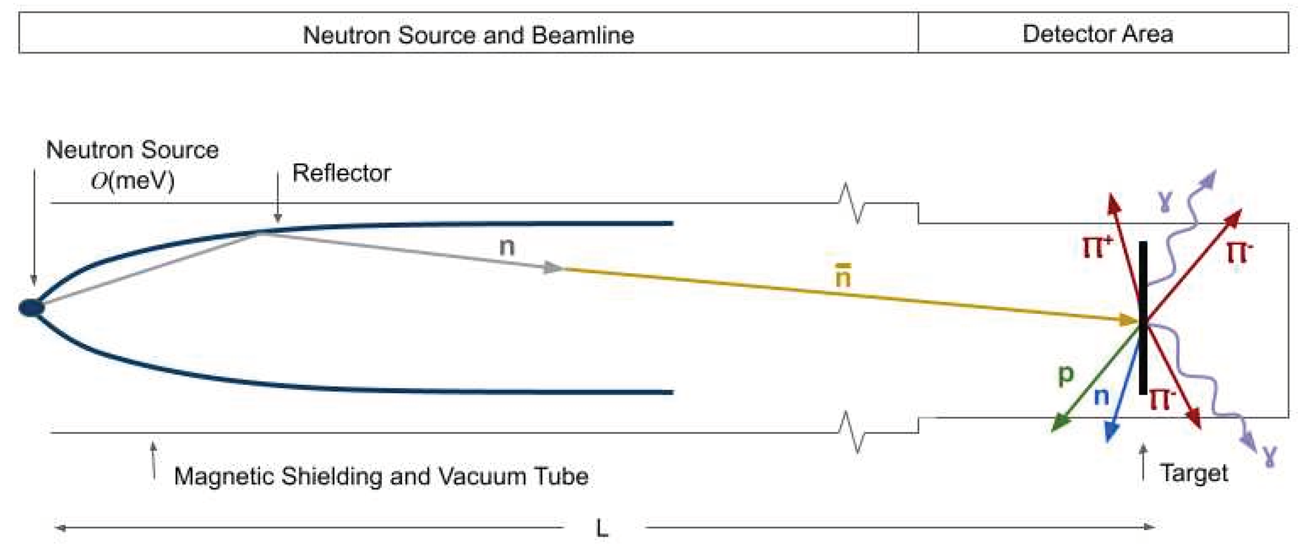
A schematic view of a free neutron oscillation experiment can be viewed in
Figure 1. A flux of slow (moderated) neutrons is reflected and guided from the source through a magnetically shielded region of longitudinal length
L to a thin carbon target disk (thickness ~
m). Around 100% of antineutrons would annihilate in this target. A new mode of operating a
search based on coherent
n and
mirror reflection has been proposed [
20] which can potentially increase the sensitivity of a search by another order of magnitude. This is an interesting and exciting possibility, although the validity of this approach remains to be experimentally tested.
An alternative approach to looking for
with neutrons in flight can be made. Here,
would proceed via sterile neutron transitions [
12]. This search requires magnetic field scans of the neutron flight volumes rather than the neutrons being in a quasi-free state, as would be the case for
Figure 1.
The key detection feature for both types of searches is that, should one of the neutrons convert into an antineutron, it will annihilate with a nucleon in the target disk, producing a characteristic multi-pion final state for which any detector must be optimised.
The HIBEAM and NNBAR programs [
1] use the principles described above. NNBAR would exploit the so-called Large Beam Port (LBP), which corresponds to three normal-sized beam ports. It would also benefit from a cold liquid deuterium moderator [
21] and high reflectivity neutron optics. The propagation length of neutrons at NNBAR would be around
m. The HIBEAM annihilation detector would be of a smaller scale than the NNBAR detector, exploiting the cold neutron beam available at a beamline of the ANNI design [
13]. The propagation length is around
m.
The sensitivity of a search with free neutrons is traditionally quantified by the figure of merit (), with , where is the number of neutrons per unit time reaching the annihilation foil after seconds of flight. The depends on the neutron flux, propagation length, neutron velocity spectrum, beam divergence, and running time.
The
values that HIBEAM and NNBAR would be expected to achieve [
1] are
and
, respectively, where
is the
obtained at the last search with free neutrons at the ILL [
14]. A substantial enhancement to the expected sensitivities could be achieved with the approach of Ref. [
20] though the usefulness of this approach remains to be tested by direct calculations similar to those done in Ref. [
15].
3. Annihilation Detector
The does not take into account the effect of an imperfect annihilation detector. Detectors for ESS searches must be able to, at the very least, match the performance of those utilized at the ILL and, ideally, given advances in detector technologies in recent decades, exceed it. This implies a signal efficiency of at least and sufficient background rejection capability such that zero background events remain after event selections.
3.1. Guiding Principles behind the Design of an Annihilation Detector
The detector is used to measure a dominantly pionic final state, typically comprised of between 2–8 (with an average of ~5) pions [
22,
23]. The pions are expected to be roughly isotropically distributed in angle; for annihilation channels used in this analysis. Kaon production during annihilation is heavily suppressed due to phase space effects and is not considered here. Resonances, such as
,
and
mesons, are included and considered unstable within the nucleus. Particle generation is calculated via the annihilation process at a particular radial position within the nucleus, simulated via a nuclear model of Fermi (gas) motion and including an attractive antinucleon potential. Nuclear transport (so-called final state interactions) is handled via a stochastic intranuclear cascade model [
22,
23,
24,
25]. Nuclear knockouts, such as protons emitted from the nucleus following nuclear transport and final state interactions, can also be produced but generally have lower kinetic energies. The simulation is validated against low-energy interactions from available antiproton data [
22,
25]. For a full overview of all the inner workings of the generator, see Ref. [
25].
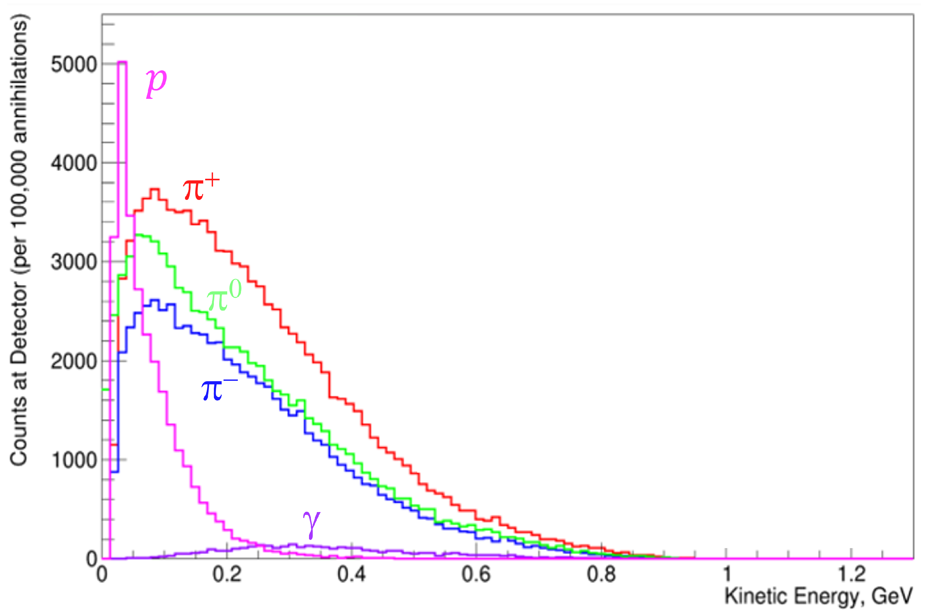
The distribution of kinetic energies of outgoing particles generated by the annihilation, including those resulting from scattering and final state interactions, are shown in
Figure 2. The decay products of heavy resonances are included. The pion and photon energies extend up to around
MeV, though they peak at around
MeV (for pions) and
MeV (photons). The photon energies are larger, as they arise from heavy resonance decays. Protons typically have the lowest kinetic energies; the kinetic energy distribution peaks at around
MeV.
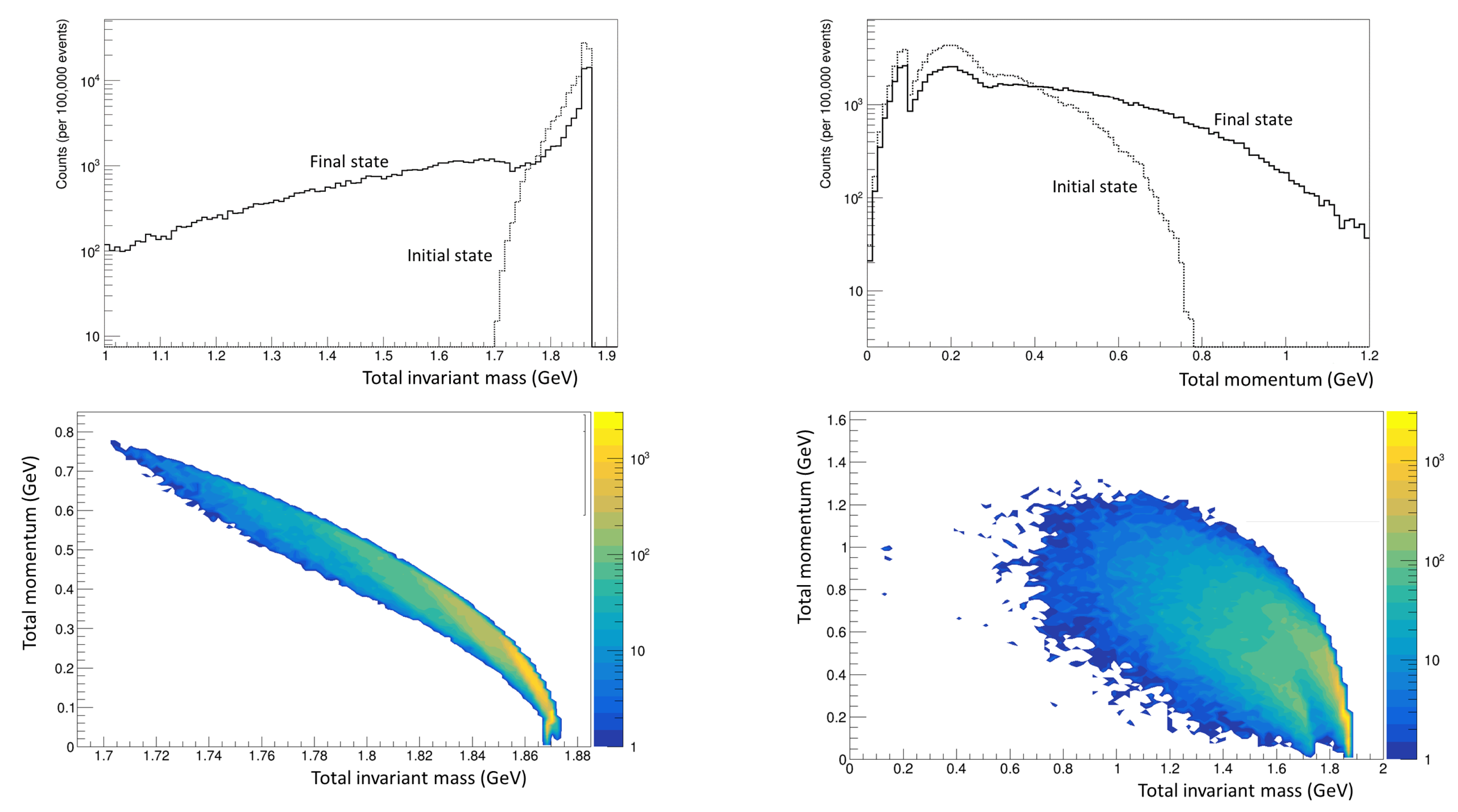
The invariant mass of the antineutron-nucleon system is ~
GeV/c
. However, due to final state interactions and meson absorption, values far lower than this may be observed. This is seen in
Figure 3, which shows the annihilation’s initial and final invariant mass distributions. The initial state is defined here to comprise the mesonic system produced after the antineutron-nucleon annihilation. The final state is the system of pions and photons produced after nuclear effects are taken into account and resonances have decayed. Note that the tail leading to low values of invariant mass (≲1 GeV) for the final state is due to absorption of mesons, and so acts as a loss when only considering this parameter space. This curve includes photons resulting from the resonance decays. Such effects can similarly affect predictions of other kinematic quantities.
Figure 3 also shows the distribution of the total vector sum of the mesons’ (pions’) momenta, which extends to high values even within the initial state due to Fermi motion and the presence of an attractive antinucleon potential [
23]. The tail of the final state’s total vector momentum of all pions and photons elongates due to both the absorption of mesons as well as the decay of heavy resonances, generally leading to further kinematic imbalance in the total vector momentum on an event-by-event basis for the mesonic system. The correlation between the total momentum and invariant mass for the initial and final states is also shown in
Figure 3. The final state distribution shows the importance of absorption and rescattering via final state interaction effects, especially in the prediction of the invariant mass.
Given that these experiments are looking for an ultra-rare process, the ultimate goal in designing a neutron oscillation detector is the possibility to claim a discovery with only one event recorded. This need motivates a number of the guiding principles of the detectors’ designs, which will be outlined below.
A common vertex of origin in the foil with at least two associated charged pion tracks needs to be reconstructed (to ~mm precision). Excellent particle identification (PID) is required; for example, it must be possible to discriminate between signal-charged pions and protons arising due to spallation backgrounds. This can be achieved via exploitation of measurements of the specific energy loss , which is particularly well measured with time projection chambers (TPCs). Furthermore, it is important that the momentum and energies of all annihilation and nuclear products be measurable in order to reconstruct event kinematics and exploit event-level characteristics of the signal event, such as the expected isotropy of produced particles. Corrections based on statistical averages are not allowed due to the rare nature of the process being measured, as one will never have many events to make such types of corrections. However, since the annihilation event happens on a nucleus and not in free space, the rejection power of some observables such as total energy and invariant mass will be degraded, implying that some of the overall demands on the calorimeter energy reconstruction for the signal final-state particles can be relaxed. Since a significant fraction of the available energy is tied up in the rest masses of the pions, accurate PID and thus measurements of the multiplicities of different types of particles are themselves indirect energy measurements. For a final-state with four pions, nearly 600 MeV of the total energy is accounted for. Precision electromagnetic calorimetry is, however, needed. Neutral pions, a large part of the expected signal, will require reconstruction via their decay . In addition, timing measurements, from a dedicated cosmic veto and from the individual detector components, are needed to reject backgrounds from cosmic rays (charged and neutral). The detector must also be sufficiently well granulated to be able to cope with the flux of gammas from neutron capture at the target and other beam-related backgrounds.
The trigger system for the detector must be able to identify and read out annihilation candidate events within a reasonably short time window to minimize overlaid detector hits from unrelated background events. This was an issue in the ILL experiment, where the relatively high trigger time window (150 ns) meant that multiple gamma events from neutron capture in the target were included, accounting for as much as 32% of the total trigger rate (~4 Hz). With fast scintillator and/or Cherenkov detectors read out with high-speed analog-to-digital converters (ADCs), the time windows can be substantially reduced. In the most pessimistic case where the trigger timing resolution is limited to the ADC clock interval, the maximum trigger window would be double the ADC clock period (e.g., 50 ns for a 40 MHz ADC rate similar to LHC [
26]) due to the arbitrary timing of the arriving neutrons. However, a modern trigger/DAQ system capable of fine timing extraction from shaped, digitized pulses may allow smaller trigger timing windows to be applied. In the simplest scenario, the trigger will accept events with multiple hits in the scintillator layers exceeding a minimum threshold. Selectivity could be further improved by including additional trigger criteria based on event topology and/or particle identification based on the calorimeter data.
3.2. Design of HIBEAM and NNBAR Annihilation Detectors
Based on the discussion above, detectors for HIBEAM and NNBAR are being designed (a prototype calorimeter comprising scintillators and lead glass is also under construction [
27]). The designs are being studied with
GEANT4. The principal features of the designs which are being considered are discussed below.
Tracking and measurement would be provided by a TPC. Three-dimensional tracking could also be performed with a silicon tracker to be placed inside the vacuum tube, which guarantees good vertex resolution and corrects any possible multiple scattering effects when particles travel through the vacuum tube (to be made of steal or aluminum);
A stack of 10 scintillator slats is needed for particle range measurements. The slats are arranged in layers with the slat orientation arranged orthogonally for each layer. By reading out on each end of the scintillator, rudimentary tracking can be done with the scintillator stack to supplement the TPC and silicon trackers;
An electromagnetic calorimeter made of lead glass would be used to measure the photons from decay. This choice of active material is motivated by the need to maximally absorb the energy of the neutral pions in an effort to avoid statistical fluctuations in energy deposits given the expected "intermediate" energy range (200–400 MeV) of the particles. Moreover, as the energy deposited is measured via Cherenkov radiation, lead glass provides some important directional information through the orientation of the Cherenkov cone;
A dedicated cosmic veto and overburden surrounding the detector is also needed, though this is not in the current design shown in this work.
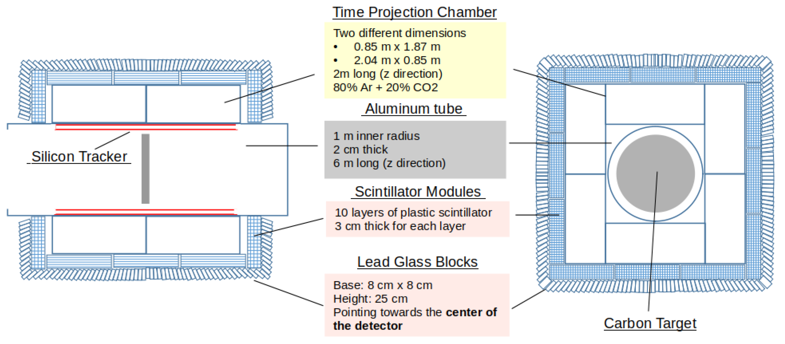
The NNBAR detector is shown in
Figure 4. A box geometry is currently being considered. The detector is 600 cm long in the longitudinal (
z) direction and has a width and height of 515 cm. Sizes for each detector component are specified in the figure.
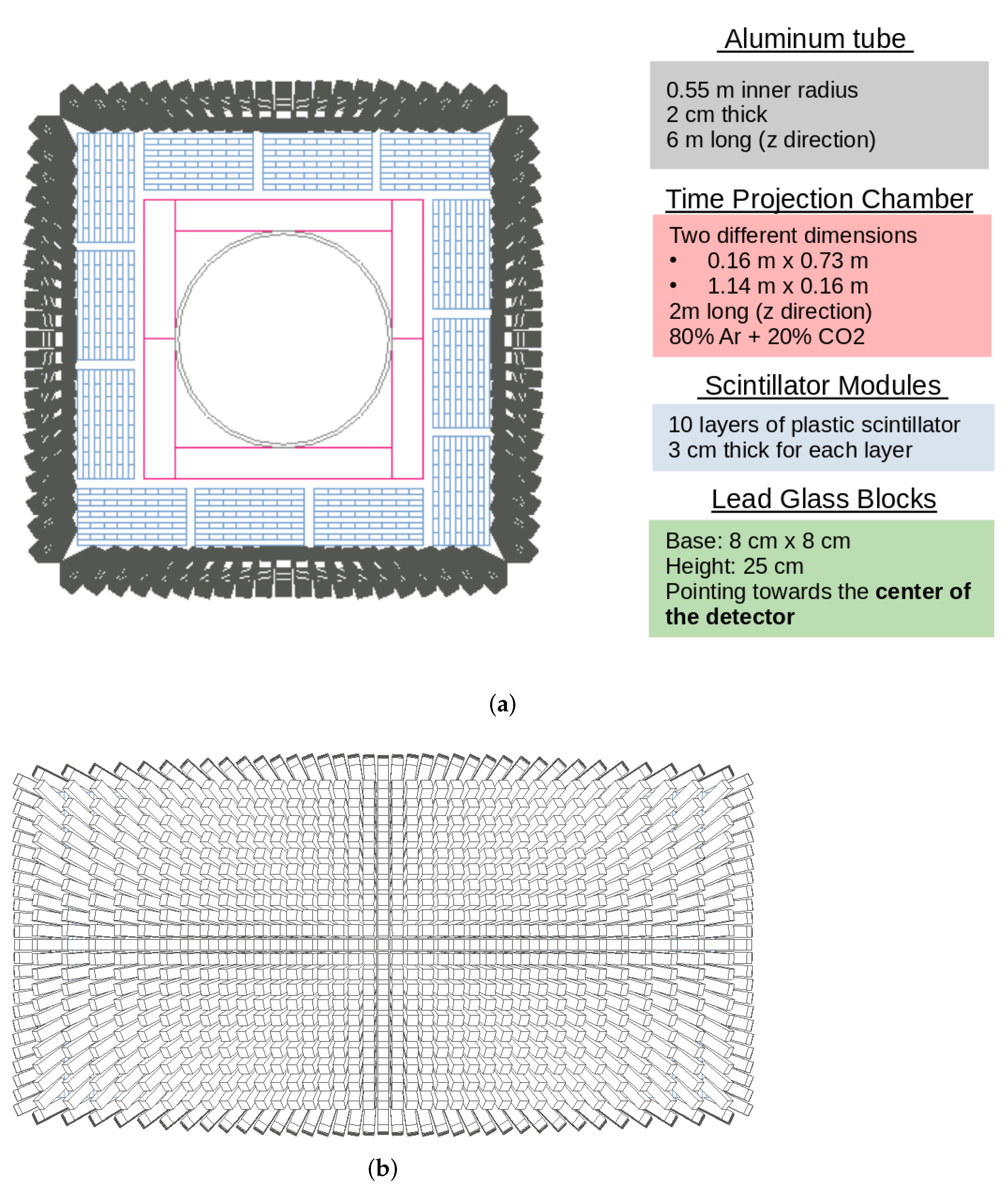
The preliminary detector designs for the HIBEAM experiment are similar to the NNBAR detector, albeit without silicon tracking. A cross-sectional and side view of the detector, together with specifications of dimensions, are shown in
Figure 5. As can be seen, the size of the TPC modules is reduced, though the scintillator, and lead glass dimensions remain unchanged compared to the NNBAR detector. The HIBEAM detector is of the same length as the NNBAR detector in the longitudinal direction, though, after taking into account the smaller TPC, it is reduced in transverse size compared to the NNBAR design.
The following sections show distributions related to the detector performance for signal and cosmic muon background events. Where distributions of specific quantities for HIBEAM and NNBAR are similar, only the NNBAR-related distribution is shown.
4. Signal and Background Simulations
The HIBEAM/NNBAR software framework [
19] was used as an interface for a number of simulations needed to predict signal and background processes. For the NNBAR detector, a simulation was used of neutrons transported to the target disk via an optimized differential reflector following emission from a liquid-deuterium moderated neutron source [
28,
29]. For HIBEAM, a simulated sample of neutrons produced for a beamline of the ANNI concept was used [
13]. A model of antineutron-nucleon annihilation with subsequent nuclear effects [
22,
23] was used to predict the post-annihilation particle states. Decays, transportation and interactions in the detector medium were studied with the
Geant4 simulation.
Cosmic ray muons may also create signals in the NNBAR detector. The signature of these events in the detector was studied using the Cosmic-ray Shower Library (CRY) [
30] interfaced with the
Geant4 simulation.
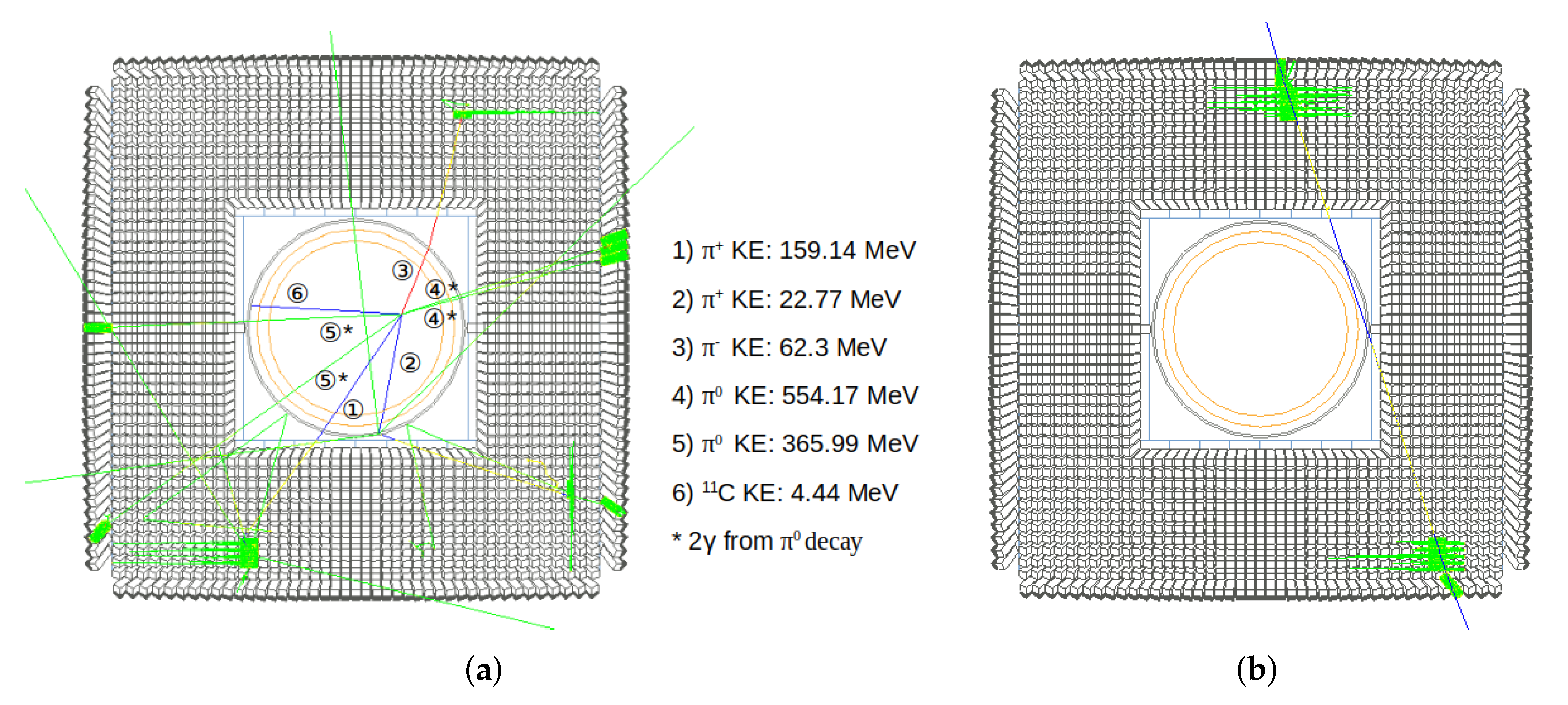
Figure 6a shows a signal event with five final-state pions in the NNBAR detector with a nuclear fragment from the carbon target. When considering the charge conservation of an annihilation event, the total charge is six. This is contributed by the 6 protons in the
nucleus, and the orbital electrons are ignored. The pions have energies ranging from around 20 to 600 MeV.
Figure 6b shows a cosmic muon of kinetic energy 3.4 GeV impinging the NNBAR detector. The particle enters from the top detector module and leaves the detector from the bottom.
5. Particle Identification
In order to robustly suppress background and characterise a possible signal event, particle identification is required. A number of tools are available. Studied here is the specific energy loss () in the TPC, which will allow for discrimination between charged pions and protons, identification via the two-gamma decay using the calorimeter, and cosmic muon discrimination using timing-sensitive parts of the detector.
5.1. Energy Loss in the TPC
The TPC chambers in the current Geant4 simulations are filled with 80% Ar and 20% CO. Ideally, the TPC simulation should cover the calculation of ionization, electron drift and avalanches given a detailed geometry and high voltage. However, this would significantly increase the time and complexity of the simulation. As the current focus of the simulations is the overall response of the particles to the detector, an alternative approach is used, where the TPC modules are constructed as rectangular boxes made of Ar/CO. Each module is divided into cells to imitate the readout pad. The energy deposited and number of electrons per cell for each event, instead of the readout signal, are simulated with this setup.
The TPC
can be computed in terms of the number of electrons induced per cm (
/cm). The
/cm of a particle in the
row of a TPC module can be approximated by the equation below.
Here, is the number of electrons induced in row i, and is the total track length in row i. Collecting the electron yield in all rows gives a distribution of these values.
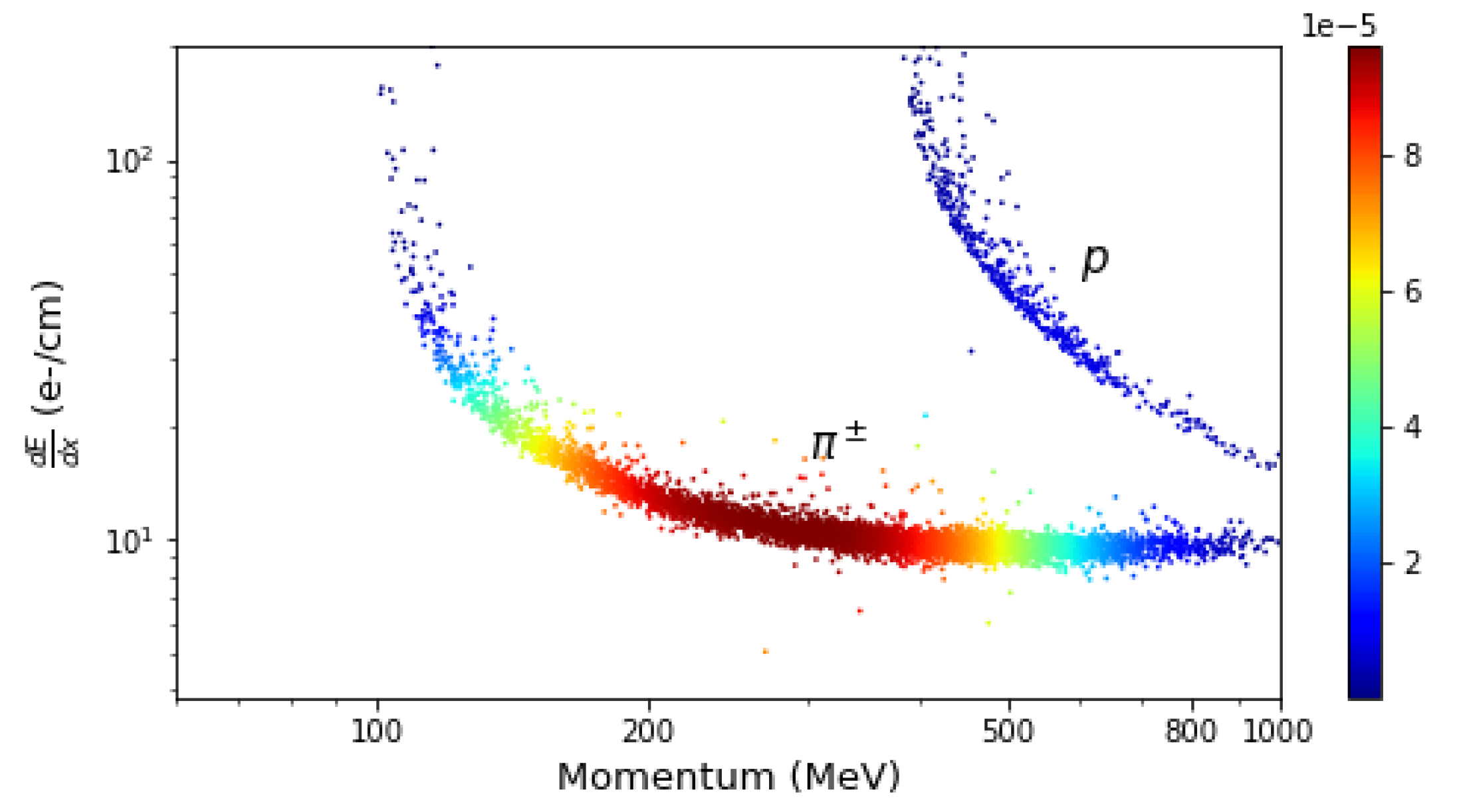
Using a sample of signal events, the
in the TPC for each particle is then computed. The
value per particle is presented as a function of the particle’s true momentum in
Figure 7. Bands of charged pions and protons can be seen. Nuclear fragments are blocked by the aluminium tube and thus do not penetrate to the TPC. It must be noticed that in the real NNBAR experiment, the momentum of the particles will not actually be measured, owing to the need for magnetic shielding in the neutron propagation region.
Figure 7 is, however, important for validating the current simulation methods.
5.2. Neutral Pion Reconstruction
Neutral pions decay ~99% of the time to two photons, the energies of which are related to the rest mass by , where and are the energy of the two respective photons and is the angle between the two momentum vectors of the photons.
The gammas from the leave no trace in the silicon layers and TPC. However, they interact with the calorimeter medium, and one can thus measure the photon energies through the Cherenkov generated photons. The angle between the gammas, (), can be determined by considering the position difference of the different detector elements that fired and assuming a common point of origin determined to high precision with tracking measurements of charged pions. Photon conversions are also possible in the aluminium tube. In such cases, tracks of and will be seen by the TPC. Both and carry the energy of the original gamma and will be detected by the calorimeter.
In order to check the
reconstruction accuracy, a sample of simulated single
events with each
produced in a random direction and possessing a kinetic energy of 250 MeV was studied. Each pion was produced at the centre of the NNBAR detector.
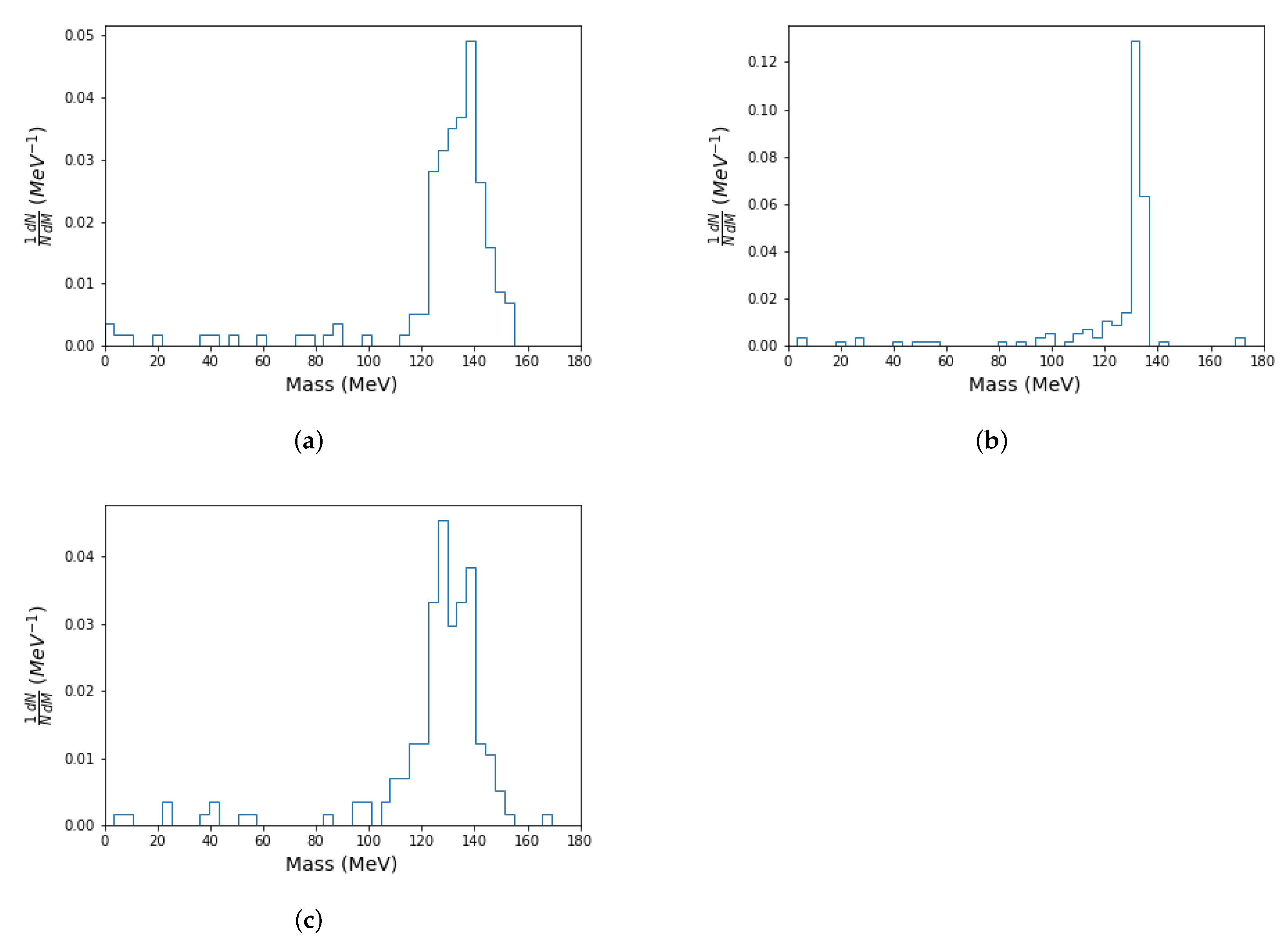
Figure 8 shows the diphoton invariant mass distribution. The distribution is shown for the cases where (a) the true photon energies are used, and the angle between them is determined geometrically using the positions of the energy depositions, (b) the deposited energy and true angle are used and (c) the deposited energy and geometrically determined angle are used. Incomplete energy reconstruction and an imprecise angle determination can both lead to a degradation of the neutral pion reconstruction, with the angle measurement contribution being largest. A tail at lower values of the diphoton mass is also seen. This corresponds to the situation where a photon converts into an electron-positron pair in the detector, and the energy depositions from one of these particles is wrongly assumed to be from a photon. Energy from an electron or positron is then combined with a photon to form a candidate diphoton mass.
If the reconstructed invariant mass of the two photons falls in the range MeV, these two photons would be identified as photons from a decay. In the case where the geometrically determined angle and deposited energies are used, ~ of decays which are reconstructed will fall in the mass window MeV.
5.3. Cosmic Muon Identification with Timing
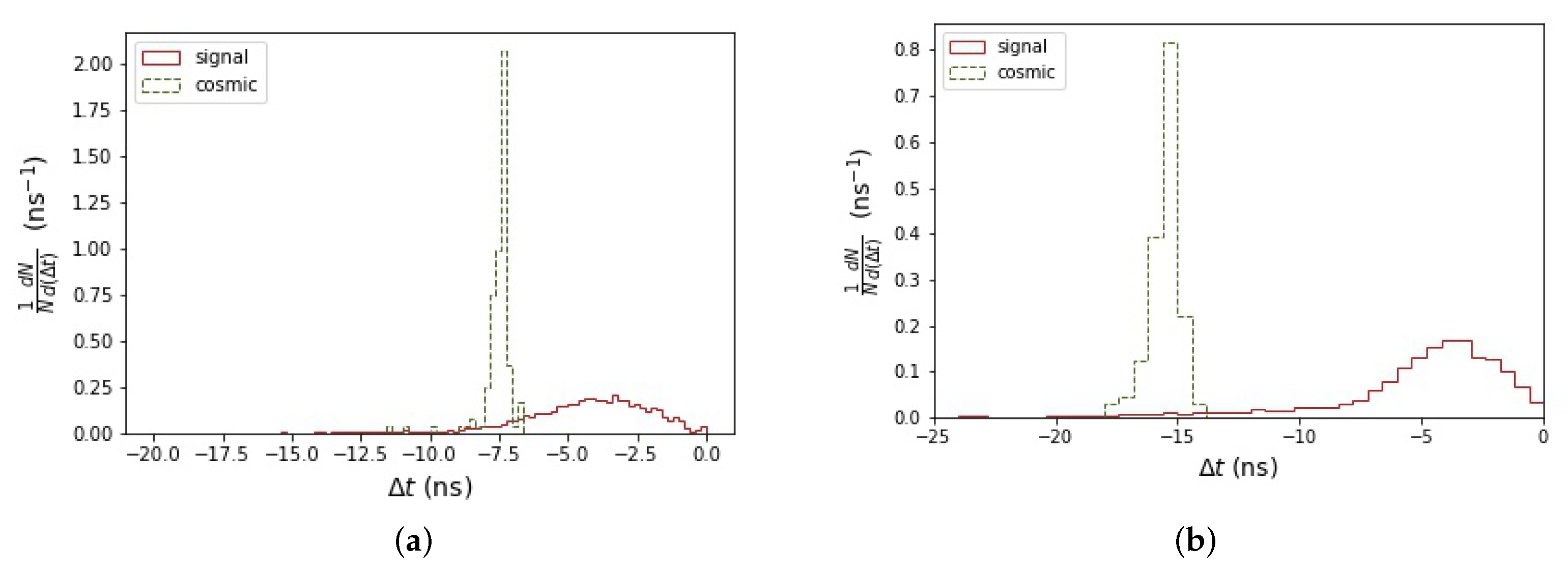
Timing measurements in the detector play a vital role in determining whether particles emanate from a common annihilation process. Particles from external sources may be identified and rejected by assuring that the particle travel direction must be outwards. This can be achieved by comparing the time difference () between the time of the first () and last () signals in the scintillators.
Each cosmic event contains one charged cosmic muon passing through the detector, which would leave a track in the TPC that can be pointed back to the target disk. Since the cosmic muons cross the top and bottom of the detector,
for the cosmic background is expected to be larger than for the signal. This can be seen in
Figure 9, which shows the
distribution for the HIBEAM and NNBAR detectors, with the separation between the signal and cosmic background growing, as expected from geometric considerations with the larger detector. It should be noted that a good separation would thus be expected from the scintillators in the present
Geant4 design alone. The development of a dedicated scintillator-based cosmic ray veto shield surrounding the detector would add further separation power, as would the utilisation of timing information from the lead glass calorimeter components. Typical timing resolutions for scintillator staves are 1–1.5 ns [
31].
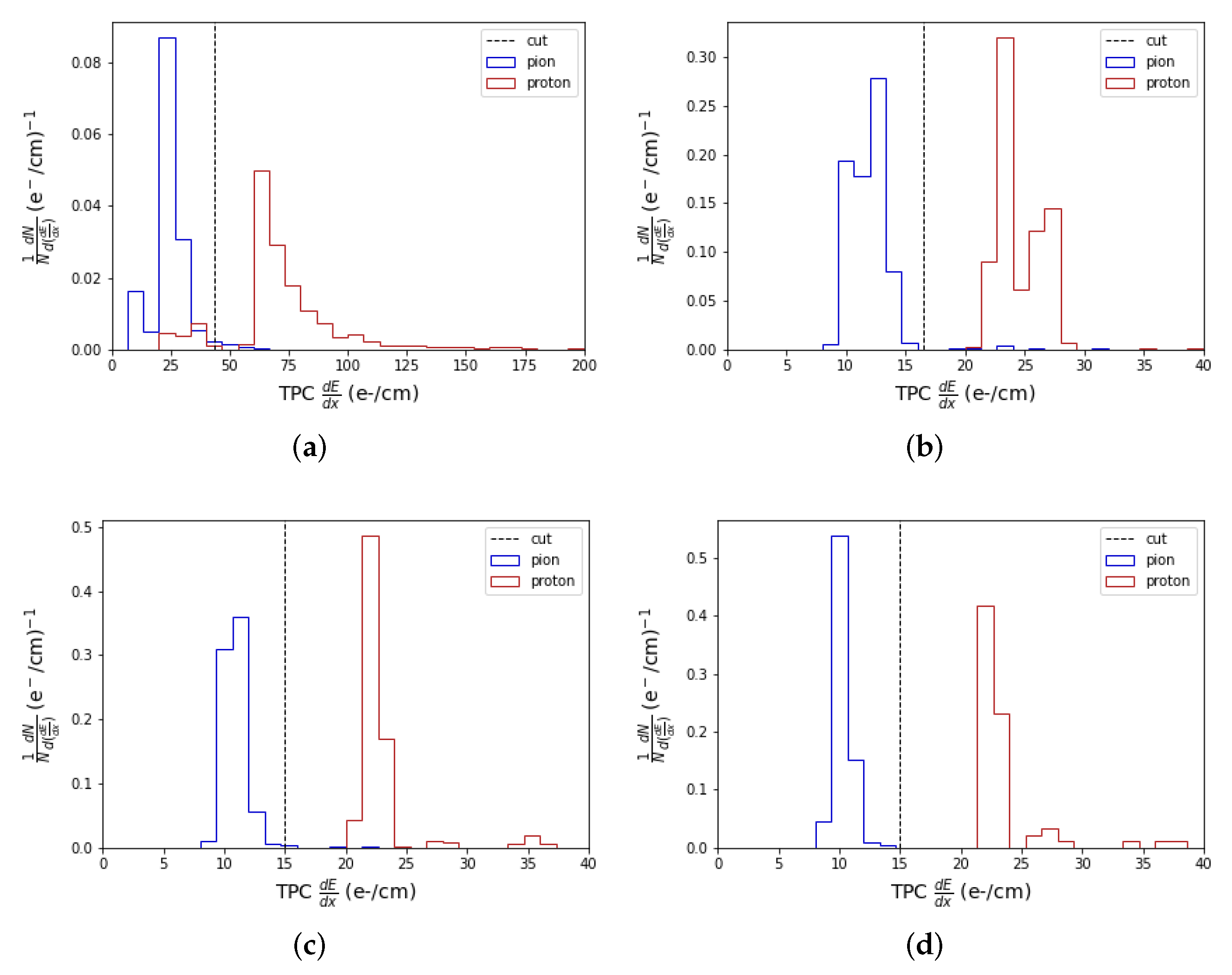
5.4. Charged Pion and Proton Definitions
An important task for a free
experiment is the ability to separate charged pions from protons. This can be done by using information from the particle
in the TPC and the number of scintillator layers travelled by the particle (the so-called scintillator range).
Figure 10 shows the TPC
distribution of charged pions and protons that can penetrate scintillators at the layers 1, 5, 7 and 10, where the lowest (highest) layer number corresponds to the layer closest to (furthest from) the TPC. Good separation between protons and pions is observed, which increases in layer number. This allows a PID selection to be made for particles penetrating a specific number of layers.
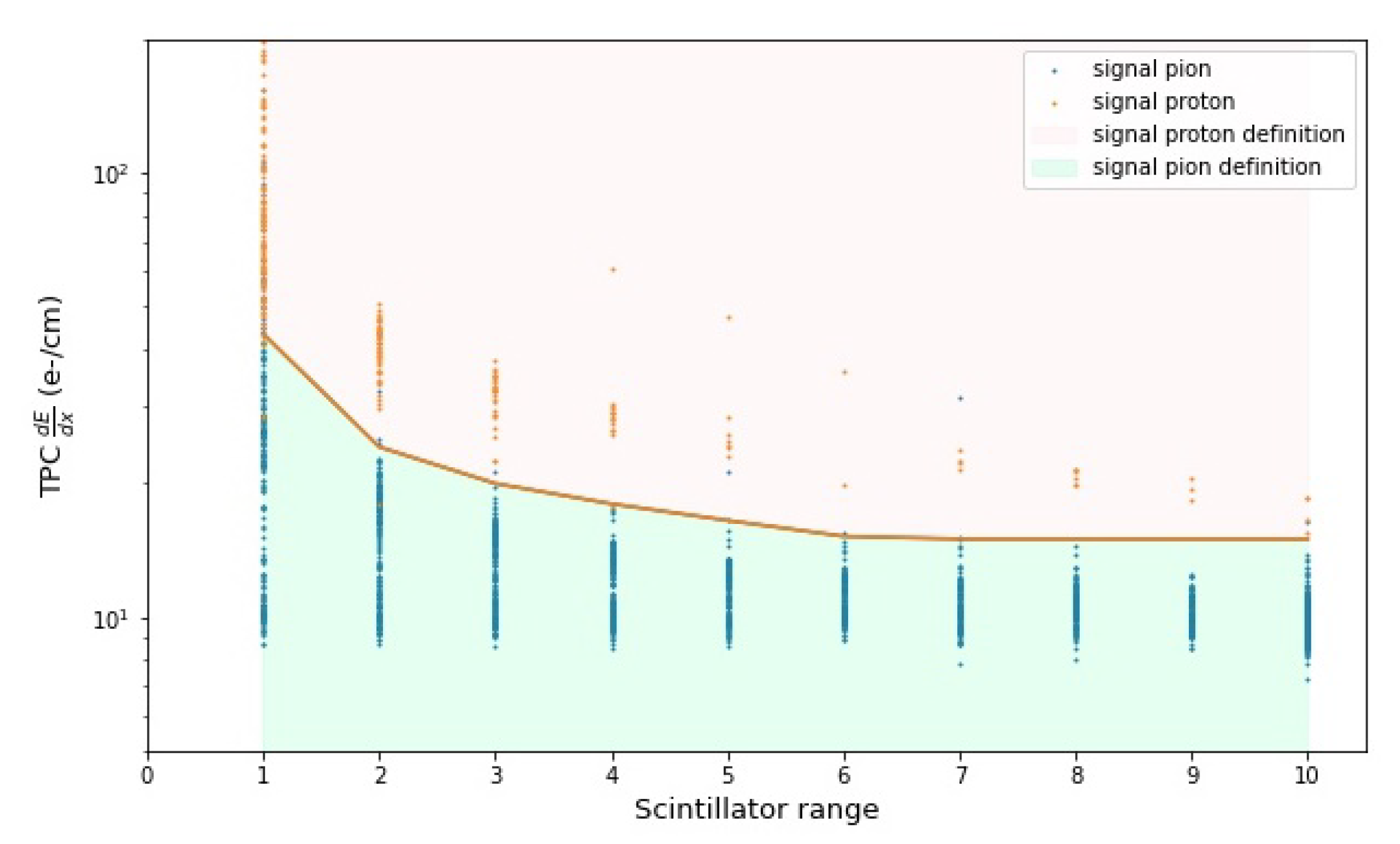
PID selections can be made by utilising information in the TPC
and scintillator range, as shown in
Figure 11. Particles above the defined boundary are tagged as protons, whereas those below it are tagged as charged pions. The PID definitions for protons and charged pions are given below.
Here, refers to the cut value for particles that can pass through N scintillator layers. When testing the object definition with simulated signal events, ~ (~) of the charged pions (protons) passing through the detector can be correctly identified.
6. Event Level Distributions
Beyond quantities characterising the identity of individual particles, it is important to study observables which use information from many particles in the observed final state. A number of such quantities are studied here: pion multiplicities, the total invariant mass, and sphericity.
In order to study these variables, the kinematic quantities of the detected particles, such as their kinetic energy, mass and momentum direction, have to be determined. The kinetic energy of a particle can be estimated by the amount of energy deposited in the calorimeter. A charged particle leaves a track in the TPC and a cone surrounding that particle with opening angle 25 degrees is used to associate with that particle energy depositions in the scintillator staves and lead glass calorimeter. The kinetic energy would be the sum of the total energy deposited. The momentum direction of a charged particle can be determined by the track in the silicon detectors or TPC. The mass of the charged particle (pion or proton for this study) is determined by the object definition. Energy loss in a calorimeter module that cannot be associated with any TPC track is considered to be a photon. A neutral pion is constructed with a photon pair. The term “detector level" is used in this section to refer to distributions calculated using the above quantities and definitions.
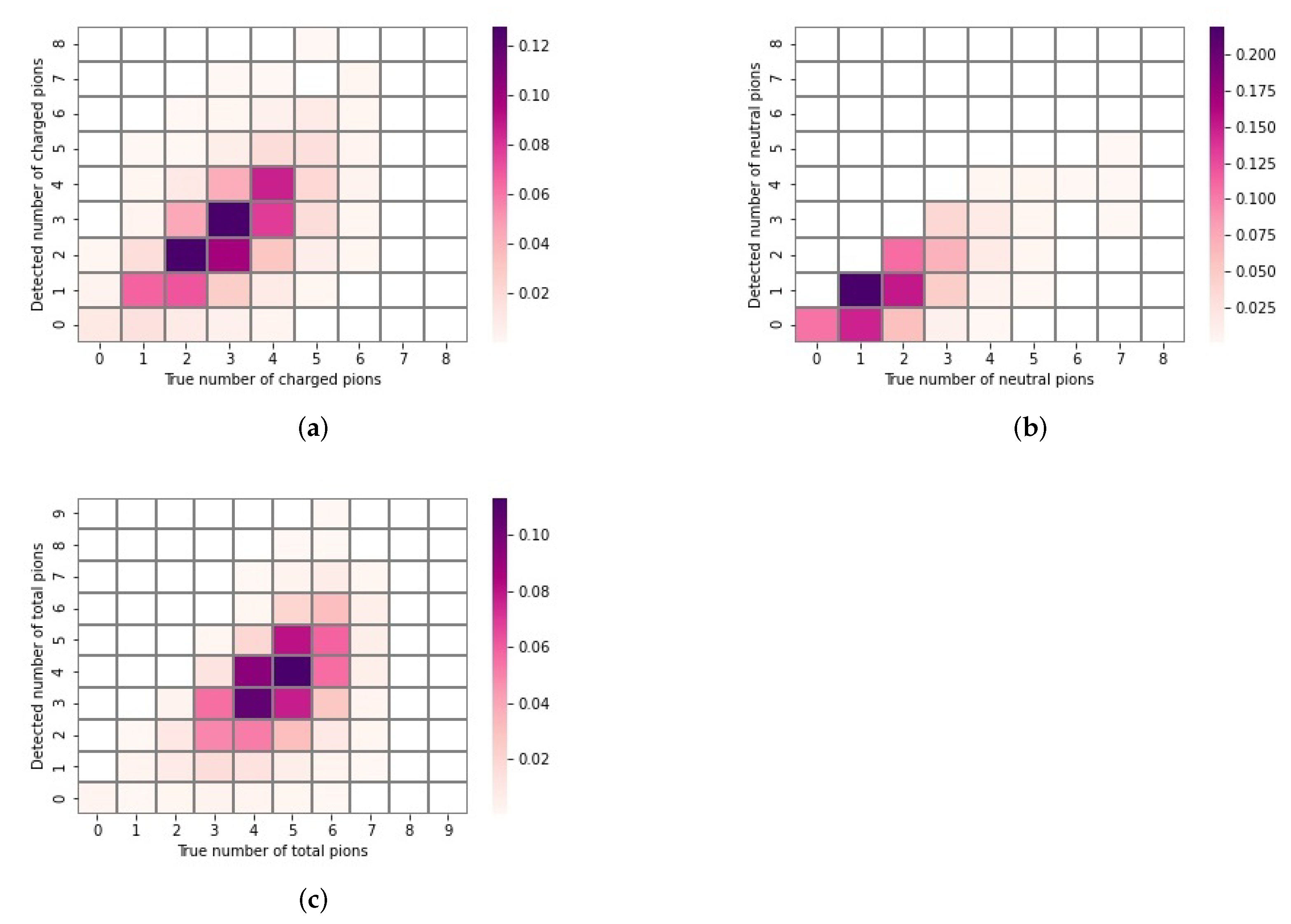
6.1. Neutral and Charged Pion Multiplicity
The multiplicities of neutral and charged pions in an event are key observables to be used to determine whether annihilation happened in the target. The true and detector-level multiplicities are shown. The multiplicities of charged and neutral pions and the total number of pions in each annihilation event are shown in
Figure 12. The detector-level multiplicities versus true multiplicities are presented. As can be seen, the number of charged pions at the detector level is typically the same as the true number generated, though there are observable migration effects. For example, some charged pions are lost through geometric effects, leading to an underestimation of charged pion multiplicity. An overestimation can also occur if, eg, a proton or an electron or positron from a photon conversion is falsely identified as a pion. Around 75% (
) of signal events at NNBAR (HIBEAM) contain two charged pions passing through the TPC, which will be necessary for the reconstruction of an annihilation vertex. The detector-level neutral pion multiplicity shows a more unbalanced migration effect in that there is a greater tendency for the multiplicity to be underestimated. This is due to the need to find two photons for each pion and the effect of geometric acceptance.
6.2. Invariant Mass Reconstruction
A naive expectation of the final state invariant mass is that it should match that of an antineutron/nucleon mass (~
GeV) system. However, nuclear effects complicate this picture. At the detector level, the invariant mass
W of an event is given below.
Here, the index
i represents charged pions and photons in an event. The particle momentum
and energy
are determined by energy deposited in the calorimeter and object definitions.
Figure 13 shows the invariant mass distributions of annihilation events at truth and detector levels for the signal and cosmic muon background. The cosmic background is shown in the case of a single muon event, taken to be misidentified as a pion. The true signal shows a strong peak around ~
GeV, as expected, though there is a broad tail at lower masses extending to around 1 GeV. The detector level signal does not reproduce the shape of the true signal distribution and corresponds to a broad distribution extending up to around 2 GeV. The difference between the detector level and true invariant mass distribution arises due to geometric acceptance effects, charged pions not being stopped in the detector, and the misidentification of pions in the object definition. Events containing only a cosmic muon correspond with low values of invariant mass and there is clear separation between these and signal events.
6.3. Sphericity
Particles in the signal final state are expected to be distributed isotropically. The sphericity event shape variable can thus be used as a sensitive variable to discriminate the signal and backgrounds. Sphericity (
S) is defined such that a perfectly isotropic (spherical) event has
S = 1. To define sphericity, it is first necessary to write down the energy-momentum tensor corresponding to the kinematic information of the event, as below.
Here, the index i runs through all particles measured from the experiment. Eigenvalues , and can be obtained from the tensor. These eigenvalues are normalized and ordered such that and .
The sphericity
S of the event is defined as:
Figure 14 shows the analogous distribution of sphericity for true signal events and detector-level signal and cosmic muon background events. As expected, the pure cosmic ray events have small values of sphericity, while signal events have larger sphericity. The discrepancy between true and detector-level sphericity arises due to the same factors as for the invariant mass variable.
7. Discussion and Summary
The HIBEAM/NNBAR program is a step-wise experimental program searching for the conversion of neutrons to antineutrons and/or sterile neutrons with goal of providing laboratory proof of baryon number violation. The program can lead to an improvement in sensitivity for neutron-antineutron conversion of three orders of magnitude. To achieve this, an annihilation detector meeting specific demands is needed.
As studied here, the annihilation of baryon numbers in an antineutron-nucleon reaction gives rise to a characteristic set of properties which a detector can be designed to measure. A strong robustness of a signal observation with a small number of events is necessary. Given the scientific impact of a discovery, even the observation of one annihilation event candidate may, even if not fully conclusive, motivate years of further data-taking.
The task described in this paper is to study an experimental setup which records the annihilation final state as completely as possible and with as good resolution as possible for each annihilation final state parameter. The experiment must be able to suppress backgrounds to allow a zero-background selection, as was achieved at the last experiment with free neutrons. Early designs of annihilation detectors have been made and studied with models of signal and cosmic muon background. The next stages of this work correspond to the continued development of the detector models and sensitive variables. Of key importance is the study of models for all potential background sources. While cosmic muon backgrounds were used here as a starting point, it is one of many sources. Examples include neutral cosmic rays, skyshine [
32], and high energy spallation products both inside and outside of the beampipe. A large flux of gammas from activated nuclei in the target foil and elsewhere is also expected and must be dealt with. Simulations with PHITS [
33] showed that, for HIBEAM (NNBAR), a gamma flux of
(
) gammas/s from the target foil is expected. The granularity and read-out timing window should ensure that only several such gammas could contribute to a background event or interfere with a signal event. This will be fully quantified.
The experimental task of designing a sensitive annihilation detector is unusual and interesting, as the signal particles to detect are in the few hundred MeV range, i.e., in principle too high for nuclear physics and too low for particle physics. This is a regime where calorimetry (electromagnetic or hadronic) is hampered by poor shower statistics. Charged hadrons are unlikely to deposit all their energy with EM processes alone and, if they do not interact hadronically, they will only deposit a fraction of their kinetic energy. Multiple scattering leads to non negligible scattering angles for low-mass particles (like pions) at these energies. This motivates the choices made here of exploiting precision detection techniques where they can usefully be done, e.g. a TPC for particle identification and an electromagnetic calorimeter for neutral pion reconstruction. Furthermore, the setup itself imposes some important and inevitable constraints which impact the optimisation of the final design. The most severe of these is the large aperture (inner diameter ~2 m) needed to meet the requirements on neutron flux. Thus, detection of the isotropic emission of annihilation products can never be efficient. Due to the large diameter of the vacuum vessel, it has to have thick walls to withstand the air pressure, leading to multiple scattering effects. This motivates the investigation of the potential of tracking inside the beampipe to mitigate the effect of multiple scattering on search sensitivity.
A neutron-neutron annihilation event has a characteristic signature which can be exploited in searches. A multi-pion final state with an invariant mass up to 1.9 GeV is extremely distinctive. Quantities which are sensitive to the event topology, such as sphericity, have been shown to be promising discriminants. This work will continue with other event-shape variables.
To conclude, Geant4-based models have been a part of ongoing design work for annihilation detectors to observe conversions at ESS. Initial studies of discriminating observables have been shown. Previous experiments realised zero background searches with detector technologies appropriate for the 1990s. The detector under design in this paper exploits more recent and sophisticated technologies and would be expected to also achieve superb background rejection. Demonstrating this is a main goal of this work, which is itself part of a program to develop conceptual designs for the HIBEAM/NNBAR experiments.
Author Contributions
Conceptualization, B.M., S.-C.Y., A.O., D.M., K.D., S.S., V.S., C.B., G.B.; methodology, B.M., S.-C.Y., D.M., A.O., S.S., V.S., J.B.; software, B.M., S.-C.Y., K.D., J.B., E.S.G.; formal analysis, S.-C.Y., B.M.; writing—original draft preparation, B.M., S.-C.Y., D.M., J.B., S.S., A.O.; writing—review and editing, S.-C.Y., B.M., J.B., K.D., D.M., A.N., A.O., V.S. and S.S.; supervision, B.M., D.M., V.S.; funding acquisition, D.M., V.S. All authors have read and agreed to the published version of the manuscript.
Funding
This work is in part funded by the European Union Framework Programme for Research and Innovation Horizon2020 initiative for the HighNESS project under grant agreement 951782. The authors also gratefully acknowledge project grant support from Vetenskapsrå det.
Institutional Review Board Statement
Not applicable.
Informed Consent Statement
Not applicable.
Data Availability Statement
Data are available upon reasonable request to the corresponding authors.
Conflicts of Interest
The authors declare no conflict of interest.
References
- Addazi, A.; Anderson, K.; Ansell, S.; Babu, K.S.; Barrow, J.L.; Baxter, D.V.; Bentley, P.M.; Berezhiani, Z.; Bevilacqua, R.; Biondi, R.; et al. New high-sensitivity searches for neutrons converting into antineutrons and/or sterile neutrons at the HIBEAM/NNBAR experiment at the European Spallation Source. J. Phys. G 2021, 48, 070501. [Google Scholar] [CrossRef]
- Sakharov, A.D. Violation of CP Invariance, C asymmetry, and baryon asymmetry of the universe. Pisma Zh. Eksp. Teor. Fiz. 1967, 5, 32–35, [Usp. Fiz. Nauk161,no.5,61(1991)]. [Google Scholar] [CrossRef] [Green Version]
- Berezhiani, Z. From Fields to Strings: Circumnavigating Theoretical Physics: Ian Kogan Memorial Collection; World Scientific: London, UK, 2005; pp. 2147–2195. [Google Scholar] [CrossRef] [Green Version]
- Babu, K.S.; Mohapatra, R.N.; Nasri, S. Post-Sphaleron Baryogenesis. Phys. Rev. Lett. 2006, 97, 131301. [Google Scholar] [CrossRef] [PubMed] [Green Version]
- Babu, K.S.; Bhupal Dev, P.S.; Mohapatra, R.N. Neutrino mass hierarchy, neutron-anti-neutron oscillation from baryogenesis. Phys. Rev. D 2009, 79, 015017. [Google Scholar] [CrossRef] [Green Version]
- Babu, K.S.; Bhupal Dev, P.S.; Fortes, E.C.F.S.; Mohapatra, R.N. Post-Sphaleron Baryogenesis and an Upper Limit on the Neutron-Antineutron Oscillation Time. Phys. Rev. D 2013, 87, 115019. [Google Scholar] [CrossRef] [Green Version]
- Mohapatra, R.N.; Okada, N. Affleck-Dine baryogenesis with observable neutron-antineutron oscillation. Phys. Rev. D 2021, 104, 055030. [Google Scholar] [CrossRef]
- Barbier, R.; Bérat, C.; Besançon, M.; Chemtob, M.; Deandrea, A.; Dudas, E.; Fayetg, P.; Lavignacdh, S.; Moreaui, G.; Perezc, E.; et al. R-parity violating supersymmetry. Phys. Rept. 2005, 420, 1–202. [Google Scholar] [CrossRef] [Green Version]
- Calibbi, L.; Ferretti, G.; Milstead, D.; Petersson, C.; Pöttgen, R. Baryon number violation in supersymmetry: Neutron-antineutron oscillations as a probe beyond the LHC. JHEP 2016, 5, 144, [Erratum: JHEP 10, 195 (2017)]. [Google Scholar] [CrossRef] [Green Version]
- Nussinov, S.; Shrock, R. N-anti-N oscillations in models with large extra dimensions. Phys. Rev. Lett. 2002, 88, 171601. [Google Scholar] [CrossRef] [PubMed] [Green Version]
- Girmohanta, S.; Shrock, R. Nucleon decay and n-n¯ oscillations in a left-right symmetric model with large extra dimensions. Phys. Rev. D 2020, 101, 095012. [Google Scholar] [CrossRef]
- Berezhiani, Z. A possible shortcut for neutron–antineutron oscillation through mirror world. Eur. Phys. J. C 2021, 81, 33. [Google Scholar] [CrossRef]
- Soldner, T.; Abele, H.; Konrad, G.; Märkisch, B.; Piegsa, F.M.; Schmidt, U.; Theroine, C.; Sánchez, P.T. ANNI—A pulsed cold neutron beam facility for particle physics at the ESS. EPJ Web Conf. 2019, 219, 10003. [Google Scholar] [CrossRef] [Green Version]
- Baldo-Ceolin, M.; Benetti, P.; Bitter, T.; Bobisut, F.; Calligarich, E.; Dolfini, R.; Dubbers, D.; Eisert, F.; El-Muzeini, P.; Genoni, M.; et al. A new experimental limit on neutron-antineutron transitions. Phys. Lett. B 1990, 236, 95–101. [Google Scholar] [CrossRef]
- Gudkov, V.; Klinby, E.; Meirose, B.; Milstead, D.; Nesvizhevsky, V.V.; Protosav, K.V.; Rizzi, N.; Snow, W.M.; Wagner, R.; Yiu, S.Z. A Possible Neutron-Antineutron Oscillation Experiment at PF1B at the Institut Laue Langevin. Symmetry 2021, 13, 2314. [Google Scholar] [CrossRef]
- Agostinelli, S.; Allison, J.; Amako, K.A.; Apostolakis, J.; Araujo, H.; Arce, P.; Asai, M.; Axen, D.; Banerjee, S.; Barrand, G.J.N.I.; et al. GEANT4–a simulation toolkit. Nucl. Instrum. Meth. A 2003, 506, 250–303. [Google Scholar] [CrossRef] [Green Version]
- Allison, J.; Amako, K.; Apostolakis, J.E.A.; Araujo, H.A.A.H.; Dubois, P.A.; Asai, M.A.A.M.; Barrand, G.A.B.G.; Capra, R.A.C.R.; Chauvie, S.A.C.S.; Chytracek, R.A.C.R.; et al. Geant4 developments and applications. IEEE Trans. Nucl. Sci. 2006, 53, 270. [Google Scholar] [CrossRef] [Green Version]
- Allison, J.; Amako, K.; Apostolakis, J.; Arce, P.; Asai, M.; Aso, T.; Bagli, E.; Bagulya, A.; Banerjee, S.; Barrand, G.J.N.I.; et al. Recent developments in Geant4. Nucl. Instrum. Meth. A 2016, 835, 186–225. [Google Scholar] [CrossRef]
- Barrow, J.; Brooijmans, G.; Damian, J.I.M.; DiJulio, D.; Dunne, K.; Golubeva, E.; Kamyshkov, Y.; Kittelmann, T.; Klinkby, E.; Kókai, Z.; et al. Computing and Detector Simulation Framework for the HIBEAM/NNBAR Experimental Program at the ESS. EPJ Web Conf. 2021, 251, 02062. [Google Scholar] [CrossRef]
- Nesvizhevsky, V.V.; Gudkov, V.; Protasov, K.V.; Snow, W.M.; Voronin, A.Y. Experimental Approach to Search for Free Neutron-Antineutron Oscillations Based on Coherent Neutron and Antineutron Mirror Reflection. Phys. Rev. Lett. 2019, 122, 221802. [Google Scholar] [CrossRef] [Green Version]
- Santoro, V.; Andersen, K.H.; DiJulio, D.D.; Klinkby, E.B.; Miller, T.M.; Milstead, D.; Muhrer, G.; Stroble, M.; Takibayev, A.; Zanini, L.; et al. Development of high intensity neutron source at the European Spallation Source. J. Neutron Res. 2020, 22, 209–219. [Google Scholar] [CrossRef]
- Golubeva, E.S.; Barrow, J.L.; Ladd, C.G. Model of n¯ annihilation in experimental searches for n¯ transformations. Phys. Rev. D 2019, 99, 035002. [Google Scholar] [CrossRef] [Green Version]
- Barrow, J.L.; Golubeva, E.S.; Paryev, E.; Richard, J.M. Progress and simulations for intranuclear neutron-antineutron transformations in
. Phys. Rev. D 2020, 101, 036008. [Google Scholar] [CrossRef] [Green Version]
- Golubeva, E.S.; Kondratyuk, L.A. Annihilation of low energy antineutrons on nuclei. Nucl. Phys. B Proc. Suppl. 1997, 56, 103–107. [Google Scholar] [CrossRef]
- Barrow, J.L. Towards Neutron Transformation Searches. Ph.D. Thesis, University of Tennessee, Knoxville, TN, USA, 2021. [Google Scholar]
- Evans, L.; Bryant, P. LHC Machine. J. Instrum. 2008, 3, S08001. [Google Scholar] [CrossRef] [Green Version]
- Dunne, K.; Meirose, B.; Milstead, D.; Oskarsson, A.; Santoro, V.; Silverstein, S.; Yiu, S.C. The HIBEAM/NNBAR Calorimeter Prototype. arXiv 2021, arXiv:2107.02147. [Google Scholar]
- Frost, M.J. Searching for Baryon Number Violation at Cold Neutron Sources. Ph.D. Thesis, University of Tennessee, Knoxville, TN, USA, 2019. [Google Scholar]
- Klinkby, E.; Batkov, K.; Mezei, F.; Schønfeldt, T.; Takibayev, A.; Zanini, L. Voluminous D2 source for intense cold neutron beam production at the ESS. arXiv 2014, arXiv:1401.6003. [Google Scholar]
- Hagmann, C.; Lange, D.; Wright, D. Cosmic-ray shower generator (CRY) for Monte Carlo transport codes. In Proceedings of the 2007 IEEE Nuclear Science Symposium Conference Record, Honolulu, HI, USA, 26 October–3 November 2007; Volume 2, pp. 1143–1146. [Google Scholar]
- Baldini, W.; Blondel, A.; Calcaterra, A.; Jacobsson, R.; Khotjantsev, A.; Kudenko, Y.; Kurochka, V.; Lanfranchi, G.; Mefodiev, A.; Mineev, O.; et al. Measurement of parameters of scintillating bars with wavelength-shifting fibres and silicon photomultiplier readout for the SHiP Muon Detector. JINST 2017, 12, P03005. [Google Scholar] [CrossRef]
- Mokhov, N.V.; Eidelman, Y.I.; Rakhno, I.L.; Tchelidze, L.; Tropin, I.S. MARS15 Simulation of Radiation Environment at the ESS Linac. In Proceedings of the 13th Meeting of the Task- Force on Shielding Aspects of Accelerators, Targets and Irradiation Facilities, Dresden, Germany, 10–12 October 2016. [Google Scholar]
- Sato, T.; Iwamoto, Y.; Hashimoto, S.; Ogawa, T.; Furuta, T.; Abe, S.I.; Kai, T.; Tsai, P.E.; Matsuda, N.; Iwase, H.; et al. Features of Particle and Heavy Ion Transport code System (PHITS) version 3.02. J. Nucl. Sci. Technol. 2018, 55, 684–690. [Google Scholar] [CrossRef] [Green Version]
Figure 1.
A schematic view of a free experiment showing the expected pionic final state.
Figure 1.
A schematic view of a free experiment showing the expected pionic final state.
Figure 2.
The distribution of the final state kinetic energies of outgoing annihilation-generated particles. In red, are shown; in green, ; blue is ; pink shows protons, p; and purple shows photons, , resulting from certain heavy resonance decays.
Figure 2.
The distribution of the final state kinetic energies of outgoing annihilation-generated particles. In red, are shown; in green, ; blue is ; pink shows protons, p; and purple shows photons, , resulting from certain heavy resonance decays.
Figure 3.
The initial and final state distributions of invariant mass (top left), the absolute value of the total momentum (top right), the relationship between the total momentum and invariant mass for the initial (bottom left) and final (bottom right) states.
Figure 3.
The initial and final state distributions of invariant mass (top left), the absolute value of the total momentum (top right), the relationship between the total momentum and invariant mass for the initial (bottom left) and final (bottom right) states.
Figure 4.
Schematic overview of the NNBAR detector design.
Figure 4.
Schematic overview of the NNBAR detector design.
Figure 5.
The HIBEAM detector in Geant4. A cross-sectional view (a) and side view (b) are shown. The dimension of the components are labelled in (a).
Figure 5.
The HIBEAM detector in Geant4. A cross-sectional view (a) and side view (b) are shown. The dimension of the components are labelled in (a).
Figure 6.
Event displays with the NNBAR detector showing (a) a signal event with five pions; (b) a cosmic muon. Red (blue) color in the figure represents a negatively (positively) charged particle.
Figure 6.
Event displays with the NNBAR detector showing (a) a signal event with five pions; (b) a cosmic muon. Red (blue) color in the figure represents a negatively (positively) charged particle.
Figure 7.
The expected mean energy loss in the TPC, , for simulated pions and protons.
Figure 7.
The expected mean energy loss in the TPC, , for simulated pions and protons.
Figure 8.
Distribution of the diphoton mass for simulated events containing a single neutral pion using (a) the true energies of the photons and the geometrically determined angle between them, (b) the deposited energy and the true angle, and (c) and the deposited energy and the geometrically determined angle.
Figure 9.
Timing quantity, , for signal and cosmic muon background for the HIBEAM (a) and NNBAR (b) detectors.
Figure 9.
Timing quantity, , for signal and cosmic muon background for the HIBEAM (a) and NNBAR (b) detectors.
Figure 10.
Expected distributions of the mean rate of energy loss, , for protons (orange) and pions (blue), for different ranges in scintillator layers for the particles. The selection windows for are also shown - selected pions (protons) correspond to the region to the left (right) of the dashed vertical line. The scintillator ranges are (a) layer 1; (b) layer 5; (c) layer 7; (d) layer 10.
Figure 11.
The expected mean rate of energy loss, , for protons and pions in the TPC, shown for the range in scintillator layers for each particle.
Figure 11.
The expected mean rate of energy loss, , for protons and pions in the TPC, shown for the range in scintillator layers for each particle.
Figure 12.
True and detector-level multiplicities for (a) charged, (b) neutral and (c) all pions.
Figure 12.
True and detector-level multiplicities for (a) charged, (b) neutral and (c) all pions.
Figure 13.
The invariant mass distributions from the signal and cosmic background events.
Figure 13.
The invariant mass distributions from the signal and cosmic background events.
Figure 14.
The expected distribution of sphericity for signal events at the generator level and detector level and for cosmic ray muons at the detector level.
Figure 14.
The expected distribution of sphericity for signal events at the generator level and detector level and for cosmic ray muons at the detector level.
| Publisher’s Note: MDPI stays neutral with regard to jurisdictional claims in published maps and institutional affiliations. |
© 2022 by the authors. Licensee MDPI, Basel, Switzerland. This article is an open access article distributed under the terms and conditions of the Creative Commons Attribution (CC BY) license (https://creativecommons.org/licenses/by/4.0/).


 ,
, 