Article

Displacements and Stress Functions of Straight Dislocations and Line Forces in Anisotropic Elasticity: A New Derivation and Its Relation to the Integral Formalism

Karlsruhe Institute of Technology (KIT), Institute of Engineering Mechanics, D-76131 Karlsruhe, Germany
Symmetry 2021, 13(9), 1721; https://doi.org/10.3390/sym13091721
Submission received: 19 August 2021 / Revised: 6 September 2021 / Accepted: 8 September 2021 / Published: 17 September 2021
(This article belongs to the Special Issue Recent Advances in the Study of Symmetry and Continuum Mechanics II)

Abstract

:
The displacement and stress function fields of straight dislocations and lines forces are derived based on three-dimensional anisotropic incompatible elasticity. Using the two-dimensional anisotropic Green tensor of generalized plane strain, a Burgers-like formula for straight dislocations and body forces is derived and its relation to the solution of the displacement and stress function fields in the integral formalism is given. Moreover, the stress functions of a point force are calculated and the relation to the potential of a Dirac string is pointed out.

1. Introduction

Anisotropic elasticity is an important theory for deformed bodies, which can be used for three-dimensional and two-dimensional problems. Dislocations and line forces are important problems of anisotropic elasticity for many applications in material science. In particular, the topic of dislocations in anisotropic elastic media is of high relevance (see, e.g., Refs. [1,2,3]). In two-dimensional (2D) anisotropic elasticity, the displacement and stress function fields of straight dislocations and straight line forces were derived by Stroh [4,5] using the so-called Stroh formalism (see also [3]) and by Asaro et al. [6,7] using the so-called integral formalism (see also [2,8]). However, the integral formalism was originally derived from the Stroh formalism by Barnett and Lothe [9]. In two dimensions, infinitely long straight dislocation lines with Burgers vector b and body forces of strength F , and the corresponding field quantities, displacement u and stress function vector Φ , are treated by the so-called “six-dimensional integral theory”, developed by Barnett and Lothe [9]. The integral formalism connects with the eigenvectors and eigenvalues of the previously developed theories of Lekhnitskii [10] and Stroh [4] (see also [2,3,8,11]). In anisotropic elasticity, the integral formalism provides suitable expressions for the numerical modelling and implementation of line defects. Many examples of the integral formalism can be found in the book of Ting [3]. For instance, the displacement field of a straight dislocation with the direction normal to the basal plane of a hexagonal crystal was derived by Kirchner and Bluemel [12] using the integral formalism. An interesting duality between dislocations and line forces was pointed out by Ni and Nemat-Nasser [13]. Using the integral formalism, the outstanding problem of line defects in the (110)-plane of a cubic crystal was solved by Wu and Kirchner [14].
In three-dimensional (3D) anisotropic elasticity, Lazar and Kirchner [15] found the anisotropic Burgers formula which is the solution for the displacement field u for a given dislocation density tensor α like for a dislocation loop and also the formula for the stress function tensor Φ for a given dislocation density α . In particular, the plastic distortion β P of a dislocation loop gives rise to the solid angle in the Burgers formula. The 3D inverse Fourier transform of the Green tensor employed leaves over to 1-D integration over the unit circle. In 3D, there seems to be no particular advantage in putting together the dislocation density tensor α and the body force vector f , and displacement vector u and stress function tensor Φ , into aggregates. Such manipulation is, however, necessary for the generation of 2D solutions from 3D ones. It will be shown that the 2D solutions can be derived from the 3D framework in a straightforward manner based on corresponding 2D Green functions. One arrives at the level of two-dimensional Fourier transforms, which, when transformed back to real space, give the equations of the integral formalism based on the inverse Fourier transform of the 2D Green functions.
In this work, we show how the integral form of the displacement field and stress functions of straight dislocations and line forces can be derived directly from the 3D framework given by Lazar and Kirchner [15]. We show that the integral formalism is nothing but a result of the inverse Fourier transform of the Green tensor and the F -tensor. In fact, the integration of the angle ϕ , which is the elementary solid angle on the unit circle in the Fourier space, cannot be carried out and gives rise to the ϕ -integral expressions of the integral formalism. Therefore, the ϕ -integration is the remnant of the inverse Fourier transform in polar coordinates in anisotropic elasticity, a fact which is blurred in the original formulation of the integral formalism.

2. Basic Equations of Incompatible Elasticity with Dislocations and Body Forces

The basic equations of 3D anisotropic incompatible elasticity, in the presence of a body force vector f and a dislocation density tensor α , are given by (see, e.g., Refs. [16,17,18,19,20])
j σ i j = f i ,
and
ϵ j k l k β i l = α i j .
Here, j denotes the partial derivative with respect to the spatial coordinate x j . Equations (1) and (2) represent the force equilibrium equation and the incompatibility condition in the presence of dislocations, respectively. The force equilibrium Equation (1) is a fundamental field equation in the linear elasticity theory of body forces. The incompatibility condition (2) is a fundamental field equation of the linear continuum theory of dislocations. The stress tensor σ and the elastic distortion tensor β are related by the Hooke law
σ i j = C i j k l β k l ,
where C i j k l is the fourth-rank tensor of elastic constants. The tensor C i j k l possesses the symmetry properties:
C i j k l = C j i k l = C i j l k = C k l i j .
In Equations (3) and (4), it can be seen that the stress tensor σ is a symmetric tensor, whereas the elastic distortion tensor β is an asymmetric tensor. However, only the symmetric part of the elastic distortion tensor provides a contribution to the symmetric stress tensor via the Hooke law (3).
Both Equations (1) and (2) may be rewritten as:
j ( σ i j + σ i j 0 ) = 0 ,
and
ϵ j k l k ( β i l + β i l P ) = 0 ,
with
j σ i j 0 = f i ,
and
ϵ j k l k β i l P = α i j .
The quantity β P is the well-known plastic distortion tensor (or eigendistortion tensor) corresponding to the dislocation density tensor α . Note that the relation (8) has the status of the definition of α in the linear continuum theory of dislocations (see [17]). Moreover, Equations (2) and (8) imply a divergence-free dislocation density tensor
j α i j = 0 ,
which means that dislocations do not end inside the medium. The quantity σ 0 is less known but is important for the modelling of line forces (see, e.g., Refs. [19,21,22]) and for stress functions in the presence of body forces (e.g., Ref. [23]).
On the one hand, Equation (6) is satisfied by deriving the total distortion tensor ( β + β P ) from a displacement vector u according to:
β i j + β i j P = j u i ,
which is nothing but the additive decomposition of the displacement gradient. If the displacement field u possesses a jump, then its gradient can be decomposed into a continuous part β , the elastic distortion, and a discontinuous part β P , the plastic distortion. Using Equation (10), the elastic distortion tensor can be written in terms of the displacement field and the plastic distortion tensor:
β i j = j u i β i j P ,
where β P is a particular solution of (8). Of course, the decomposition (11) satisfies the incompatibility condition (2) using Equation (8).
On the other hand, Equation (5) is satisfied by deriving ( σ + σ 0 ) from an asymmetric stress function tensor of first order Φ as:
σ i j + σ i j 0 = ϵ j k l k Φ i l .
If the stress function tensor Φ possesses a jump, then its curl can be decomposed into a continuous part σ and a discontinuous part σ 0 . In particular, the stress functions of the straight line forces possess a jump [3,7,13]. Using Equation (12), the stress tensor can be written as (see also [23]):
σ i j = ϵ j k l k Φ i l σ i j 0 ,
where σ 0 is a particular solution of (7). Of course, the decomposition (13) satisfies the force equilibrium Equation (1) using Equation (7). If a body force exists, the stress function tensor, Φ , has to be combined with the tensor σ 0 as given in Equation (13).
From Equation (1), an inhomogeneous Navier equation for the elastic distortion follows:
C i j k l j l β k m = ϵ m l n C i j k l j α k n m f i ,
where the dislocation density tensor α and the body force vector f are the source fields for the elastic distortion tensor β . The solution of Equation (14) can be written as a convolution integral as follows
β i m = ϵ m n r C j k l n k G i j α l r + m G i j f j ,
where ∗ denotes the spatial convolution. This is the well-known Mura–Willis formula [24,25]. Here, G i j indicates the anisotropic elastic Green tensor satisfying the Navier equation
C i k l n k n G l j ( x x ) + δ i j δ ( x x ) = 0 ,
where x R 3 , δ i j is the Kronecker delta and δ ( . ) denotes the Dirac delta function.

2.1. Displacement Field Due to Dislocations and Body Forces

The divergence from the right (right-div) on Equation (10) gives the following inhomogeneous Laplace equation (Poisson equation) for the displacement field u :
Δ u i = m β i m P + m β i m .
Using the Green function of the Laplace operator (e.g., Ref. [26]):
Δ G Δ = δ ( x x ) ,
the so-called F -tensor (see also [15,20,27])
F m k i j = m k G i j G Δ
and substituting the Mura-Willis Formula (15) into Equation (17), the formal solution of u is given by
u i = m G Δ β i m P ϵ m n r C j k l n F m k i j α l r + G i j f j .
This is the solution of the displacement vector u for given β P , α and f and is valid for any distribution of dislocations and body forces. The first term in Equation (20) is a purely geometric part because it does not depend on the elastic properties of the medium and gives the solid angle in 3D (see [15]). Only the second and third parts depend on the elastic properties of the material due to the appearance of the tensor of elastic constants and the elastic Green tensor. Therefore, Equation (20) represents the generalized anisotropic Burgers formula for dislocations and body forces. By means of Equation (20), the displacement fields of a dislocation loop and a point force were given in [15,28,29], respectively.

2.2. Stress Functions Due to Dislocations and Body Forces

The curl from the right (right-curl) on Equation (12) gives rise to
ϵ m n j n ( σ i j + σ i j 0 ) = ϵ m n j ϵ j k l n k Φ i l = m l Φ i l Δ Φ i m .
Imposing the side condition,
j Φ i j = 0 ,
we obtain an inhomogeneous Laplace equation (Poisson equation) for the stress function tensor,
Δ Φ i j = ϵ j k l k ( σ i l + σ i l 0 ) .
Using Equations (3) and (18), we find:
Φ i j = ϵ j k l k ( σ i l + σ i l 0 ) G Δ = ϵ j k l C i l m n k β m n G Δ ϵ j k l k σ i l 0 G Δ .
Substituting Equation (15) into Equation (24), the formal solution of Φ is given by:
Φ i j = ϵ j k l k G Δ σ i l 0 + ϵ j k l C i l m n ϵ n p q C r s t p F s k m r α t q + ϵ j k l C i l m n F k n m p f p .
This is the solution of the stress function tensor Φ for given α , f and σ 0 and is valid for any distribution of dislocations and body forces. The first term in Equation (25) is a purely geometric part because it does not depend on the elastic properties of the medium. The second and third parts in Equation (25) depend on the elastic properties of the material due to the appearance of the tensor of elastic constants and the elastic Green tensor contained in the F -tensor. Using Equation (25), the stress function tensor of a dislocation loop was given in [15]. The corresponding stress function tensor of a point force is given below.

Stress Functions of a Point Force

Let us calculate the stress function tensor of a point force explicitly in anisotropic elasticity, missing in the scientific literature.
The body force vector of a point force located at the origin is given by:
f i = F i δ ( x 1 ) δ ( x 2 ) δ ( x 3 ) ,
where F i is the strength of the point force. Substituting Equation (26) into Equation (7), the solution of Equation (7) can be written as:
σ i 1 0 = F i H ( x 1 ) δ ( x 2 ) δ ( x 3 ) = F i 0 δ ( x 1 x 1 ) δ ( x 2 ) δ ( x 3 ) d x 1 .
Here, H ( . ) denotes the Heaviside step function. The singular field σ i 1 0 in Equation (27) vanishes everywhere except in the positive x 1 -axis from the origin to infinity. The 3D Green function of the Laplace operator reads (see, e.g., Ref. [26]),
G Δ = 1 4 π r ,
where r = x 1 2 + x 2 2 + x 3 2 . The 3D F -tensor is given by (see [15,20])
F k n m p = 1 8 π 2 r 0 2 π κ k κ n ( κ κ ) m p 1 d ϕ ,
where κ i = k i / k and
( κ κ ) i j = κ k C i k j l κ l .
If we substitute Equations (26)–(29) into Equation (25) and carry out the convolution and differentiation, then the stress function tensor of a point force located at the origin reads as:
Φ i j = F i 4 π ϵ j k 1 x k r ( r x 1 ) F p 8 π 2 r ϵ j k l C i l m n 0 2 π κ k κ n ( κ κ ) m p 1 d ϕ .
It is interesting to note that the first part of Equation (31), which is the purely geometric part, has the form of the potential of a Dirac string along the positive x 1 -axis (see [30,31,32]).

3. Generalized Plane Strain of Straight Dislocations and Straight Line Forces

In this Section, we consider straight dislocations and straight line forces with a line direction parallel to the x 3 -axis belonging to the framework of a generalized plane strain, which is 2D elasticity consisting of plane strain and anti-plane strain. In generalized plane strain problems of anisotropic elasticity, all field functions must be independent of the variable x 3 , all derivatives with respect to the x 3 -axis vanishes, 3 = 0 and it holds: x R 2 . Therefore, all fields of dislocations and line forces depend only on x 1 and x 2 and are two-dimensional fields.

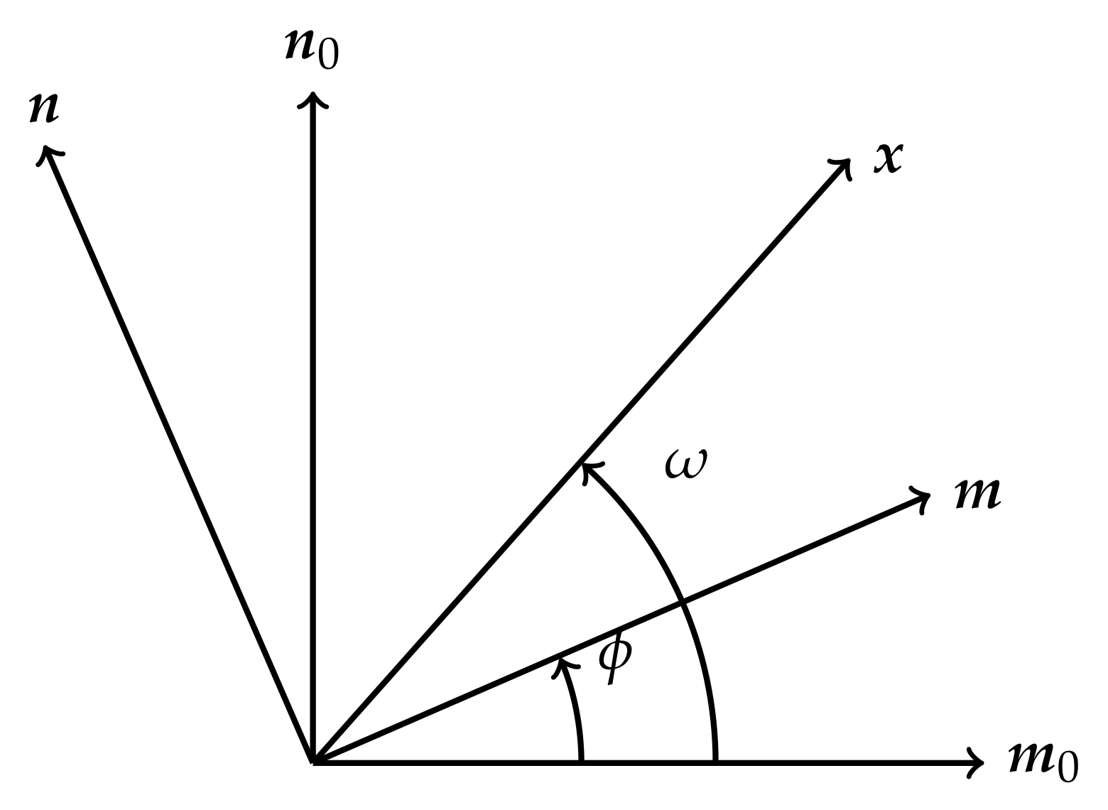
3.1. Anisotropic Elasticity of Generalized Plane Strain

For generalized plane strain, the solutions for the displacement vector and the stress function tensor, Equations (20) and (25), reduce to:
u i = α G Δ β i α P + ϵ 3 α β C j α l γ F β γ i l α j 3 + G i j f j
and
Φ i 3 = ϵ 3 β α β G Δ σ i α 0 + ϵ 3 β α C i α l γ ϵ 3 γ δ C r μ j δ F β μ l r α j 3 + ϵ 3 β α C i α l γ F β γ l j f j ,
where the Latin subscripts i , j , l , r take the values of 1, 2, 3, whereas the Greek subscripts α , β , γ , δ , μ take the values of 1 and 2 only. Therefore, we have three displacement components u i = u i ( x 1 , x 2 ) and three stress functions Φ i 3 = Φ i 3 ( x 1 , x 2 ) , which are given by the convolution of the 2D Green functions G Δ ( x 1 , x 2 ) , G i j ( x 1 , x 2 ) , the 2D F -tensor F α β i j ( x 1 , x 2 ) with the source fields of straight dislocations α j 3 ( x 1 , x 2 ) , β i α P ( x 1 , x 2 ) and the source fields of line forces f j ( x 1 , x 2 ) , σ i α 0 ( x 1 , x 2 ) .
For generalized plane strain, the Green tensor of the Navier operator reads as (see Equation (A9)):
G i j = 1 ( 2 π ) 2 0 2 π ( κ κ ) i j 1 ln | x · κ | d ϕ
and the F -tensor is given by (see Equation (A14))
F α β i j = 1 ( 2 π ) 2 0 2 π κ α κ β ( κ κ ) i j 1 ln | x · κ | d ϕ .
Here, bracket symbols of the type ( a b ) denote:
( a b ) i j = a α C i α j β b β .
The matrix ( κ κ ) 1 is the inverse of ( κ κ ) . The 2D Green function of the Laplace operator reads (see, e.g., Ref. [26]):
G Δ = 1 2 π ln | x | .

3.2. Displacements and Stress Functions of Straight Dislocations and Line Forces

Consider line defects with line direction parallel to the x 3 -axis and defect surface in the x 1 x 3 half plane for positive x 1 ( x 2 = 0 , x 1 > 0 ). For a straight dislocation with Burgers vector b j located at ( x 1 , x 2 ) = ( 0 , 0 ) , the dislocation density and the plastic distortion are given by (see also [19]):
α j 3 = b j δ ( x 1 ) δ ( x 2 ) ,
β j 2 P = b j H ( x 1 ) δ ( x 2 ) ,
satisfying Equation (8). For a straight dislocation with Equation (38), the Bianchi identity (9) is automatically fulfilled. For a straight line force with strength F j located at ( x 1 , x 2 ) = ( 0 , 0 ) , the corresponding fields are given by (see also [19])
f j = F j δ ( x 1 ) δ ( x 2 ) ,
σ j 1 0 = F j H ( x 1 ) δ ( x 2 ) ,
satisfying Equation (7). Note that the 2D expressions (40) and (41) of a line force can be directly derived from the 3D expressions (26) and (27) of a point force by the projection of the 3D fields onto the x 1 x 2 plane, namely: f j ( x 1 , x 2 ) = f j ( x 1 , x 2 , x 3 ) d x 3 and σ j 1 0 ( x 1 , x 2 ) = σ j 1 0 ( x 1 , x 2 , x 3 ) d x 3 .
Equations (32) and (33) can be written as matrix equation:
u i Φ i 3 = ϵ 3 α β C j α l γ F β γ i l G i j ϵ 3 β α C i α l γ ϵ 3 γ δ C r μ j δ F β μ l r ϵ 3 β α C i α l γ F β γ l j α j 3 f j + δ i j 2 G Δ 0 i j 0 i j δ i j 2 G Δ β j 2 P σ j 1 0 .
Equation (42) can be further performed for straight dislocations and line forces. First, substituting Equations (37), (39) and (41) into the second part of Equation (42). The convolution of the second part of Equation (42) can be computed using the relation (see also [8]):
2 G Δ H ( x 1 ) δ ( x 2 ) = ω 2 π ,
where ω is the polar angle in the x 1 x 2 plane with range 0 < ω 2 π . Second, substituting Equations (34), (35), (38) and (40) into the first part of Equation (42) and performing the convolution, we obtain:
u i Φ i 3 = 1 ( 2 π ) 2 0 2 π ϵ 3 α β κ β C j α l γ κ γ ( κ κ ) i l 1 ( κ κ ) i j 1 ϵ 3 β α C i α l γ ϵ 3 γ δ C r μ j δ κ β κ μ ( κ κ ) l r 1 ϵ 3 α β κ β C i α l γ κ γ ( κ κ ) l j 1 ln | x · κ | d ϕ b j F j + ω 2 π δ i j 0 i j 0 i j δ i j b j F j .
The first part of Equation (44) can be further simplified as follows. Choosing κ = n and ϵ 3 α β κ β = ϵ 3 α β n β = m α . Therefore, m and n are two orthogonal unit vectors in the x 1 x 2 plane. The north-west (NW) block of the matrix in the integrand in Equation (44) can be rewritten:
ϵ 3 α β κ β C j α l γ κ γ ( κ κ ) i l 1 = m α C j α l γ n γ ( n n ) i l 1 = ( m n ) j l ( n n ) i l 1 = ( n n ) i l 1 ( n m ) l j ,
using the relation (36). The north-east (NE) block of the matrix in the integrand in Equation (44) is simply ( κ κ ) i j 1 = ( n n ) i j 1 . The south-east (SE) block of the matrix in the integrand in Equation (44) reduces to
ϵ 3 α β κ β C i α l γ κ γ ( κ κ ) l j 1 = m α C i α l γ n γ ( n n ) l j 1 = ( m n ) i l ( n n ) l j 1 .
The south-west (SW) block of the matrix in the integrand in Equation (44) becomes
ϵ 3 β α C i α l γ ϵ 3 γ δ C r μ j δ κ β κ μ ( κ κ ) l r 1 = C i α l β n β C j α r μ n μ ( n n ) l r 1 C i α j α = ( m n ) i l ( m n ) j r ( n n ) l r 1 + ( n n ) i l ( n n ) j r ( n n ) l r 1 ( m m ) i j ( n n ) i j = ( m n ) i l ( n n ) l r 1 ( n m ) r j ( m m ) i j .
Now, using the 6 × 6 matrix N ( ϕ ) , which is called the fundamental elasticity matrix and is a function of the angle ϕ , of the following form (see, e.g., Refs. [2,11]):
N ( ϕ ) = ( n n ) 1 ( n m ) ( n n ) 1 ( m n ) ( n n ) 1 ( n m ) ( m m ) ( m n ) ( n n ) 1 .
Equation (44) reduces to the following Burgers-like matrix equation for a straight dislocation with Burgers vector b and a straight line force with strength F located at the position ( 0 , 0 ) in rather compact notation:
u Φ = ω 2 π I 1 ( 2 π ) 2 0 2 π N ( ϕ ) ln | x · n | d ϕ b F .
Here, I is the 6 × 6 identity matrix. The 6 × 6 matrix N ( ϕ ) is periodic in ϕ with periodicity π [3]. In Equation (49), it can be seen that the role of the solid angle is played by the polar angle ω (see also [33]). In fact, the 3D solid angle Ω is reduced to the “2D solid angle" 2 ω (compare with the 3D result in [15]). Therefore, the 2D Burgers-like Formula (49) is a decomposition into a purely geometric term, ω , and a line integral over the unit circle with elastic constants in the matrix N ( ϕ ) and a logarithmic function ln | x · n | . Equation (49) gives the solution of finding [ u ( x 1 , x 2 ) , Φ ( x 1 , x 2 ) ] T as function of the sources [ b , F ] T given at the origin.

3.3. Relation to the Integral Formalism

Now, we derive from Equation (49) a matrix equation for the displacement and stress function fields of a straight dislocation and a line force using polar coordinates in order to connect it with the integral formalism. As usual in the integral formalism [9], it is convenient to choose the following orientation of the coordinate system. The unit vectors m and n are orthogonal to each other and orthogonal to t such that m × n = t . The line defects run along an axis t which is in our case the x 3 -axis. The unit vectors m and n are rotated around t by the angle ϕ against a fixed basis ( m 0 , n 0 ) (see Figure 1)
m = m 0 cos ϕ + n 0 sin ϕ ,
n = m 0 sin ϕ + n 0 cos ϕ .
Similarly, the field vector x is given with respect to the fixed basis m 0 and n 0 and reads as (see Figure 1):
x = r ( m 0 cos ω + n 0 sin ω ) ,
with r = | x | . The inner product between the vectors x and n is given by:
x · n = r sin ( ω ϕ ) = r sin ( ϕ ω )
so that the ln-term in Equation (49) can be rewritten as:
ln | x · n | = ln r + ln | sin ( ϕ ω ) | .
The substitution of Equation (54) into Equation (49) gives a split into a radial part, ln r , and a part depending on the angle ω , namely
u ( r , ω ) Φ ( r , ω ) = 1 ( 2 π ) 2 [ 0 2 π N ( ϕ ) d ϕ ln r 2 π ω I + 0 2 π N ( ϕ ) ln | sin ( ϕ ω ) | d ϕ ] b F .
In order to simplify the ln sin -term, we use the integral equation for N given by Lothe [11] (see Appendix C)
P 0 2 π N ( ϕ ) cot ( ϕ ω ) d ϕ = 2 π I + N ( ω ) 0 2 π N ( ϕ ) d ϕ ,
where the left-hand side of Equation (56) is a principal-value integral. After the integration over ω , the following integral equation is obtained (see also [34]):
0 2 π N ( ϕ ) ln | sin ( ϕ ω ) | d ϕ = 2 π ω I + 0 ω N ( ϕ ) d ϕ 0 2 π N ( ϕ ) d ϕ .
If we substitute Equation (57) into Equation (55), we obtain the six-dimensional displacement-stress function vector of a straight dislocation with Burgers vector b and a line force with strength F located at the position ( 0 , 0 ) known in the integral formalism (see, e.g., Refs. [3,12,35]):
u ( r , ω ) Φ ( r , ω ) = 1 ( 2 π ) 2 0 2 π N ( ϕ ) d ϕ ln r + 0 ω N ( ϕ ) d ϕ 0 2 π N ( ϕ ) d ϕ b F .
Equation (58) is in agreement with the expression originally given by Kirchner [35] (see also [3,12]). In this manner, Equation (58) represents the unification of the displacement fields of a straight dislocation and a line force, given by Asaro et al. [6], and the stress functions of a straight dislocation and a line force, given by Asaro et al. [7]. Equation (58) is the solution of finding [ u ( r , ω ) , Φ ( r , ω ) ] T as function of the sources [ b , F ] T at the origin, which was originally obtained in terms of a specifically developed 2D “integral theory” without reference to the 3D solution, unknown at that time (see [2,6,7,35]). Moreover, Kirchner and Bluemel [12] have shown that Equation (58) gives the correct displacement field of straight dislocations in isotropic elasticity. Using the average value of N ( ϕ ) , given in Equation (A17), Equation (58) simplifies to:
u ( r , ω ) Φ ( r , ω ) = 1 2 π I ln r + 0 ω N ( ϕ ) d ϕ N ¯ b F .
Note that we have derived Equation (58) from the 3D solutions (20) and (25) via Equation (49) in a straightforward way. Equation (58) represents a 2D Burgers-like formula expressed in polar coordinates.

4. Discussion

In this work, we have derived a Burgers-like formula for straight dislocations and straight line forces in the framework of anisotropic incompatible elasticity. For generalized plane strain, the necessary Green functions were computed using the 2D Fourier transform. Using the 2D Fourier transform, the 2D anisotropic Green tensor of generalized plane strain has been computed as line integral over the unit circle, which is the 2D version of the famous Lifshitz–Rosenzweig–Synge 3D anisotropic Green tensor. Using the 2D anisotropic Green tensor of generalized plane strain, the displacements and stress functions of a straight dislocation with Burgers vector b and a line force with strength F located at the position ( 0 , 0 ) have been derived in a form of 2D Burgers-like formula. Moreover, the Burgers-like formula can be connected with the integral formalism. In particular, the integral formalism, specifically developed for the 2D situation, turns out to be a disguised 2D inverse Fourier transform. Rewriting the 2D Burgers-like formula in polar coordinates gives, in a straightforward way, the known expressions of the so-called integral formalism. It became obvious that the ϕ -integral representation in the integral formalism is nothing but the polar angle in the 2D Fourier transform in polar coordinates of the 2D Green tensor.
An extension of the presented sextic ( 6 × 6 ) formalism of anisotropic elasticity toward the decadic ( 10 × 10 ) formalism of piezoelectric piezomagnetic elastic media [36] and piezoelectric-piezomagnetic-magnetoelectric elastic media [37] is possible and straightforward.

Funding

This research was funded by the Deutsche Forschungsgemeinschaft grant number LA1974/4-2.

Institutional Review Board Statement

Not applicable.

Informed Consent Statement

Not applicable.

Data Availability Statement

Data sharing is not applicable to this article.

Acknowledgments

The author thanks Helmut Kirchner (Paris) for inspiring and clarifying discussions, and many helpful advices.

Conflicts of Interest

The author declares no conflict of interest.

Appendix A. 2D Anisotropic Green Tensor of the Navier Operator for Generalized Plane Strain

For generalized plane strain, the 2D Green tensor G i j of the anisotropic Navier operator
L i l = C i α l β α β ,
which is a linear elliptic differential operator of second order, is defined by
C i α l β α β G l j ( x x ) + δ i j δ ( x x ) = 0 , x R 2
with i , j , l = 1 , 2 , 3 and α , β = 1 , 2 . Using 2D Fourier transform, Equation (A2) becomes
C i α l β k α k β G ^ l j ( k ) = δ i j , k R 2 .
Therefore, the 2D Fourier transform of the Green tensor reads as
G ^ i j ( k ) = 1 k 2 ( κ κ ) i j 1 ,
where κ denotes the unit vector in the k 1 k 2 plane of the 2D Fourier space defined by κ = k / k with k = | k | . For generalized plane strain, the matrix ( κ κ ) i j 1 is the inverse of ( κ κ ) i j , defined by
( κ κ ) i j = κ α C i α j β κ β .
It can be seen that in the Fourier space, G i j ( k ) is a homogeneous function of k of degree 2 , namely 1 / k 2 .
The 2D Green tensor in real space is obtained by the inverse Fourier transform of Equation (A4):
G i j ( x ) = 1 ( 2 π ) 2 R 2 ( κ κ ) i j 1 cos ( k · x ) k 2 d 2 k = 1 ( 2 π ) 2 0 2 π ( κ κ ) i j 1 0 cos ( k κ · x ) k d k d ϕ .
In Equation (A6), d 2 k = k d k d ϕ indicates the 2D volume element in Fourier space in polar coordinates, and ϕ ( 0 < ϕ 2 π ) is an appropriate polar angle scanning a unit circle κ 2 = 1 . The integration in k is performed with the relation
0 cos ( k κ · x ) k d k = 1 2 1 k e i k κ · x d k
and the principal value integral (see Equation (32) in Section 9 in [26])
P 1 k e i k t d k = 2 γ 2 ln | t | ,
where γ denotes the Euler constant and P means the principal value. The constant term can be neglected for the Green tensor. Using Equations (A7) and (A8), the 2D Green function (A6) can be expressed as integral over the unit circle in Fourier space
G i j ( x ) = 1 ( 2 π ) 2 0 2 π ( κ κ ) i j 1 ln | x · κ | d ϕ .
Because κ ( ϕ ) varies with ϕ , the integrand ( κ κ ) i j 1 is a function of the integration variable ϕ . Note that the Green tensor (A9) is in agreement with Gel’fand and Shilov [38] using generalized functions (Equations (3) and (7) on page 129 in [38]) and with the 2D elastostatic Green function for anisotropic elasticity obtained by Wang and Achenbach [39], Wang [40] using the technique of Radon transform.
Recasting Equation (A9) as a line integral, G i j ( x ) can also be written as
G i j ( x ) = 1 ( 2 π ) 2 S 1 ( κ κ ) i j 1 ln | x · κ | d s ( κ )
with the unit circle
S 1 = { κ | κ R 2 , | κ | = 1 } .
The integral in Equation (A10) corresponds to a line integral along s ( κ ) around the unit circle S 1 .
Therefore, Equation (A9) gives the 2D Green tensor of the anisotropic Navier operator for generalized plane strain, whereas the 3D Green tensor of the anisotropic Navier operator was given by Lifshitz and Rosenzweig [28], and Synge [29] (see also [18,41]). Moreover, a closed form representation of the Green tensor for the infinite 2D orthotropic material is given by Michelitsch and Levin [42].

Appendix B. 2D Anisotropic F-Tensor for Generalized Plane Strain

For generalized plane strain, the F -tensor is defined as
F α β i j = α β G i j G Δ .
The 2D Fourier transform of F -tensor is given by
F ^ α β i j ( k ) = 1 k 2 κ α κ β ( κ κ ) i j 1 .
As the Fourier transform of the Green tensor (A4), F -tensor (A12) varies like k 2 and also its 2D inverse Fourier transform can be computed
F α β i j ( x ) = 1 ( 2 π ) 2 R 2 κ α κ β ( κ κ ) i j 1 cos ( k · x ) k 2 d 2 k = 1 ( 2 π ) 2 0 2 π κ α κ β ( κ κ ) i j 1 0 cos ( k κ · x ) k d k d ϕ
using Equations (A7) and (A8). In this manner, the 2D F -tensor reduces to an integral over the unit circle in Fourier space as
F α β i j ( x ) = 1 ( 2 π ) 2 0 2 π κ α κ β ( κ κ ) i j 1 ln | x · κ | d ϕ .
The F -tensor (A14) can also be written as line integral
F α β i j ( x ) = 1 ( 2 π ) 2 S 1 κ α κ β ( κ κ ) i j 1 ln | x · κ | d s ( κ ) .
On the other hand, the 3D F -tensor of anisotropic elasticity can be found in [15,20] (see also Equation (29)).

Appendix C. Lothe’s Integral Equation

The 6 × 6 matrix N ( ϕ ) is a function of an angle ϕ and satisfies the following eigenvalue equation (see [9,11])
N ( ϕ ) ξ α = p α ( ϕ ) ξ α , α = 1 , , 6
with the six-dimensional eigenvector ξ α and the six eigenvalues p α ( ϕ ) . The average value of N ( ϕ ) is given by
N ¯ = 1 2 π 0 2 π N ( ϕ ) d ϕ
and the average value of p α ( ϕ ) reads
p ¯ α = 1 2 π 0 2 π p α ( ϕ ) d ϕ , p ¯ α = ± i ,
satisfying the eigenvalue equation
N ¯ ξ α = ± i ξ α .
The combination of Equations (A16) and (A17) leads to
N ( ϕ ) N ¯ ξ α = ± i p α ( ϕ ) ξ α .
Substituting the integral equation for p α ( ϕ ) (see [9,11])
± i p α ( ϕ ) = 1 1 2 π P 0 2 π p α ( θ ) cot ( θ ϕ ) d θ
into Equation (A20), it gives
N ( ϕ ) N ¯ ξ α = 1 + 1 2 π P 0 2 π p α ( θ ) cot ( θ ϕ ) d θ ξ α = I + 1 2 π P 0 2 π N ( θ ) cot ( θ ϕ ) d θ ξ α .
Finally, for a complete set of eigenvectors, the following equation is valid
1 2 π P 0 2 π N ( θ ) cot ( θ ϕ ) d θ = I + N ( ϕ ) N ¯ ,
which is Lothe’s integral equation for the matrix N ( ϕ ) given in [11]. The advantage of the use of Equation (A23) is that the principal value integral on the left-hand side can be expressed in terms without the principal value inconvenience on the right-hand side.

References

  1. Hirth, J.P.; Lothe, J. Theory of Dislocations, 2nd ed.; John Wiley: New York, NY, USA, 1982. [Google Scholar]
  2. Bacon, D.J.; Barnett, D.M.; Scattergood, R.O. Anisotropic continuum theory of defects. Prog. Mater. Sci. 1980, 23, 51–262. [Google Scholar] [CrossRef]
  3. Ting, T.C.T. Anisotropic Elasticity; Oxford Science Publishers: Oxford, UK, 1996. [Google Scholar]
  4. Stroh, A.N. Dislocations and cracks in anisotropic elasticity. Phil. Mag. 1958, 3, 625–646. [Google Scholar] [CrossRef]
  5. Stroh, A.N. Steady state problems in anisotropic elasticity. J. Math. Phys. 1962, 41, 77–103. [Google Scholar] [CrossRef]
  6. Asaro, R.J.; Hirth, J.P.; Barnett, D.M.; Lothe, J. A further synthesis of sextic and integral theories for dislocations and line forces in anisotropic media. Phys. Stat. Sol. 1973, 60, 261–271. [Google Scholar] [CrossRef]
  7. Asaro, R.J.; Hirth, J.P.; Lothe, J. Stress functions for line defects in anisotropic elastic media. Scripta Metall. 1975, 9, 837–840. [Google Scholar] [CrossRef]
  8. Balluffi, R.W. Introduction to Elasticity Theory for Crystal Defects; Cambridge University Press: Cambridge, UK, 2012. [Google Scholar]
  9. Barnett, D.M.; Lothe, J. Synthesis of the sextic and the integral formalism for dislocations, Green’s function and structure waves in anisotropic elastic solids. Phys. Norv. 1973, 7, 13–19. [Google Scholar]
  10. Lekhnitskii, S.G. Theory of Elasticity of an Anisotropic Body; Holden-Day: San Francisco, CA, USA, 1950. [Google Scholar]
  11. Lothe, J. Dislocations in anisotropic media. In Elastic Strain Fields and Dislocation Mobility; Indenbom, V.L., Lothe, J., Eds.; Elsevier: Amsterdam, The Netherlands, 1992; pp. 269–328. [Google Scholar]
  12. Kirchner, H.O.K.; Bluemel, K.H. Elastic quasi-isotropy normal to the basal plane in the hexagonal system. Phys. Stat. Sol. 1976, 75, 527–532. [Google Scholar] [CrossRef]
  13. Ni, L.; Nemat-Nasser, S. A general duality principle in elasticity. Mech. Mater. 1996, 24, 87–123. [Google Scholar] [CrossRef]
  14. Wu, M.S.; Kirchner, H.O.K. Line defects in the (110)-plane of a cubic crystal—An outstanding problem solved by the integral formalism. Proc. R. Soc. Lond. A 2003, 459, 2033–2047. [Google Scholar] [CrossRef]
  15. Lazar, M.; Kirchner, H.O.K. Dislocation loops in anisotropic elasticity: Displacement field, stress function tensor and interaction energy. Phil. Mag. 2013, 93, 174–185. [Google Scholar] [CrossRef]
  16. Kröner, E. Kontinuumstheorie der Versetzungen und Eigenspannungen; Springer: Berlin, Germany, 1958. [Google Scholar]
  17. Kröner, E. Continuum theory of defects. In Physics of Defects (Les Houches, Session 35); Balian, R., Kleman, M., Poirier, J.P., Eds.; North-Holland: Amsterdam, The Netherlands, 1981; pp. 215–315. [Google Scholar]
  18. Mura, T. Micromechanics of Defects in Solids, 2nd ed.; Martinus Nijhoff: Dordrecht, The Amsterdam, 1987. [Google Scholar]
  19. Alshits, V.I.; Kirchner, H.O.K. Elasticity of multilayers, part I: Basic equations and solutions. Phil. Mag. A 1995, 72, 1431–1444. [Google Scholar] [CrossRef]
  20. Lazar, M. Micromechanics and dislocation theory in anisotropic elasticity. J. Micromech. Mol. Phys. 2016, 1, 1650011. [Google Scholar] [CrossRef] [Green Version]
  21. Nowacki, J.P. Static and Dynamic Coupled Fields in Bodies with Piezoeffects or Polarization Gradient (Lecture Notes in Applied and Computational Mechanics); Springer: Berlin, Germany, 2006. [Google Scholar]
  22. Lazar, M.; Kirchner, H.O.K. Cosserat (micropolar) elasticity in Stroh form. Int. J. Solids Struct. 2005, 42, 5377–5398. [Google Scholar] [CrossRef]
  23. Bertóti, E. Indeterminacy of first order stress functions and the stress- and rotation-based formulation of linear elas-ticity. Comput. Mech. 1994, 14, 249–265. [Google Scholar] [CrossRef]
  24. Mura, T. Continuous distribution of moving dislocations. Phil. Mag. 1963, 8, 843–857. [Google Scholar]
  25. Willis, J.R. Second-order effects of dislocations in anisotropic crystals. Int. J. Eng. Sci. 1967, 5, 171–190. [Google Scholar] [CrossRef]
  26. Vladimirov, V.S. Equations of Mathematical Physics; Marcel Dekker, Inc.: New York, NY, USA, 1971. [Google Scholar]
  27. Kirchner, H.O.K. The concept of the line tension: Theory and experiments. In Dislocation 1984; Veyssière, P., Kubin, L., Castaing, J., Eds.; Editions du CNRS: Paris, France, 1984; pp. 53–71. [Google Scholar]
  28. Lifshitz, I.M.; Rosenzweig, L.N. On the construction of the Green’s tensor for the basic equation of the theory of elasticity of an anisotropic medium. Zh. Eksper. Teor. Fiz. 1947, 17, 783–791. [Google Scholar]
  29. Synge, J.L. The Hypercircle in Mathematical Physics; Cambridge University Press: Cambridge, UK, 1957. [Google Scholar]
  30. Wentzel, G. Comments on Dirac’s theory of magnetic monopoles. Prog. Theor. Phys. Suppl. 1966, 37, 163–174. [Google Scholar]
  31. Kleinert, H. Multivalued Fields in Condensed Matter, Electromagnetism, and Gravitation; World Scientific: Singapore, 2008. [Google Scholar]
  32. Lazar, M.; Po, G. The solid angle and the Burgers formula in the theory of gradient elasticity: Line integral representation. Phys. Lett. A 2014, 378, 597–601. [Google Scholar] [CrossRef] [Green Version]
  33. Leibfried, G. Versetzungen in anisotropem Material. Z. Phys. 1953, 135, 23–43. [Google Scholar] [CrossRef]
  34. Lothe, J. Dislocations interacting with surfaces, interfaces or cracks. In Elastic Strain Fields and Dislocation Mobility; Indenbom, V.L., Lothe, J., Eds.; Elsevier: Amsterdam, The Netherlands, 1992; pp. 329–389. [Google Scholar]
  35. Kirchner, H.O.K. Line defects along the axis of rotationally inhomogeneous media. Phil. Mag. A 1987, 55, 537–542. [Google Scholar] [CrossRef]
  36. Alshits, V.I.; Kirchner, H.O.K.; Ting, T.C.T. Inhomogeneous piezoelectric piezomagnetic media. Phil. Mag. Lett. 1995, 71, 285–288. [Google Scholar] [CrossRef]
  37. Kirchner, H.O.K.; Alshits, V.I. Elastically anisotropic angularly inhomogeneous media. Part II: Green’s function for piezoelectric, piezomagnetic and magnetoelectric media. Phil. Mag. A 1996, 74, 861–885. [Google Scholar] [CrossRef]
  38. Gel’fand, I.M.; Shilov, G.E. Generalized Functions; Academic: New York, NY, USA, 1964; Volume I. [Google Scholar]
  39. Wang, C.-Y.; Achenbach, J.D. Elastodynamic fundamental solutions for anisotropic solids. Geophys. J. Int. 1994, 118, 384–392. [Google Scholar] [CrossRef] [Green Version]
  40. Wang, C.-Y. Two-dimensional elastostatic Green’s functions for general anisotropic solids and generalization of Stroh’s formalism. Int. J. Solids Struct. 1994, 31, 2591–2597. [Google Scholar] [CrossRef]
  41. Li, S.; Wang, G. Introduction to Micromechanics and Nanomechanics; World Scientific: Singapore, 2008. [Google Scholar]
  42. Michelitsch, T.; Levin, V.M. Green’s function for the infinite two-dimensional orthotropic medium. Int. J. Fract. 2000, 107, 33–38. [Google Scholar] [CrossRef]
Figure 1. The unit vectors m and n are to be turned anticlockwise from m 0 and n 0 by an angle ϕ , and the field vector x with angle ω .
Symmetry 13 01721 g001
Publisher’s Note: MDPI stays neutral with regard to jurisdictional claims in published maps and institutional affiliations.

