1. Introduction
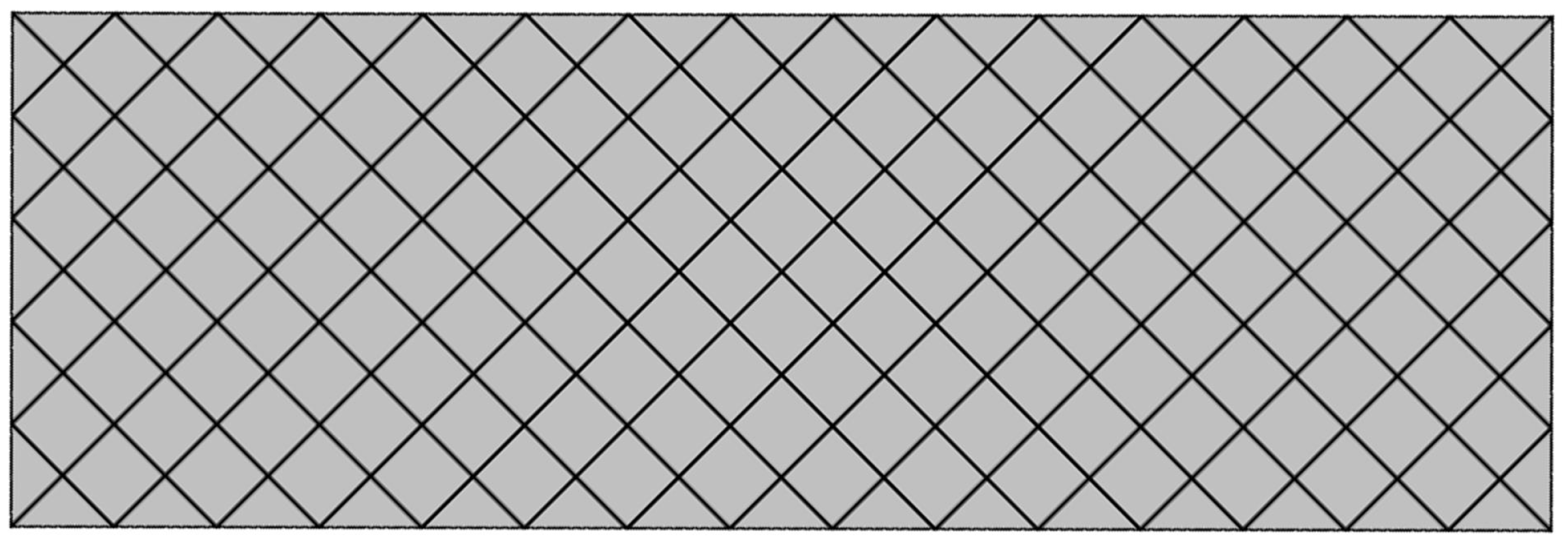
The central content of this work consists of the study of the active role of connecting elements in metamaterials whose microstructure is composed of fibers arranged in parallel planes (see
Figure 1). This metamaterial, known in the literature as a pantographic metamaterial [
1], normally exhibits non-symmetrical behavior with respect to extension/compression in uniaxial tests such as extension and compression. In fact, its behavior is mainly determined by the deformations of the individual components, fibers or connecting elements, and, specifically, in the first stage, the mechanical response is basically determined by the torsion of the connecting cylinders between the two families of fibers and the bending of the fibers themselves, while in the second stage of the test, the elongation of the fibers prevails. Since the elongation mechanism is activated earlier in the extension test than in the compression test at the same modulus of the prescribed displacement, there will be a strong asymmetry in the graphs of the two tests. This will be shown and analyzed in detail in the following sections.
As in this work, attention is paid to metamaterials, it is useful to clarify exactly in what sense the metamaterial concept is intended here. First of all, the contemporary inductivist fashioned school pretends to define a metamaterial as a material which cannot be found in nature and which exhibits an exotic behavior; this is generally obtained by looking for randomly generated microstructures and hoping that in the number of the sorted microstructures someone presents such exotic behaviors. The present work lies in a totally different school: the synthesis of a microstructure is a procedural step that follows the choice of the macroscopic mechanical behavior. In other words, one chooses the governing equations and only a posteriori looks for the microstructure that, once homogenized, produces a continuum governed by such equations.
Among the mechanical metamaterials [
2], a set of interest is represented by fibrous metamaterials, i.e., metamaterials whose microstructure is composed of fibers that can be deformed and interact with each other in different ways [
3,
4]. These metamaterials are of interest for at least two features: (i) they are very easy to manufacture and (ii) they exhibit very high mechanical performances. In nature, fibrous microstructures are often present: different microstructures lead to substantially dissimilar mechanical properties on the macroscopic scale. Notable examples of natural fibrous microstructures are typically encountered in bone tissue or wood [
5].
Moreover, as said, fibrous metamaterials are easy to manufacture, both with classical manufacturing techniques and with more modern techniques as 3D printing: the possibilities opened by the rapid development of additive manufacturing technologies are huge [
6].
A very well-performing geometry for the fibrous microstructure is known as the pantographic microstructure. It consists in at least two layers of parallel fibers that are connected to each other (see
Figure 1) by some connective elements, generally also referred to as pivots in the literature. It has been proven that, when using pantographic cells as a metamaterial microstructure, it is necessary, after homogenization, to use generalized continua [
7] and to take into account the second gradient of displacement in the strain energy. Thus, the pantographic system consisting in fibers and pivots can be modeled by taking into account all the possible deformations of these elements: bending and stretching of fibers and torsion and shear of pivots in a first simplified model. More specifically, due to the fact that the study of metamaterials is a multiscale problem, one has to consider at least two scales, and some misunderstandings can be produced. In particular, it will be shown that the strain energy of the homogenized continuum will contain a shear term which is related to the torsion of the pivots, while the shear of the pivots will contribute in a different way. For this reason, the shear of the continuum will be referred to as macro-shear or simply shear, while the shear of pivots will be referred to as micro-shear. In fact, when the micro-deformability of pivots is not negligible, it may be appropriate to specify the kinematics of the introduced generalized continua with two placement fields [
8]. It is noteworthy that such micro-mechanisms play a significant role in the deformation of natural as well as synthesized granular materials [
9].
As it will become clear in the following, a fundamental role is played by the fiber bending. In fact, this deformation is related to an energetic term that includes the second gradient of displacement. For this reason, it has been widely attempted to produce pantographic metamaterials whose pivots are perfect hinges, allowing for the experimental direct measure of a second-gradient contribution. To this aim, the role of pivots in the mechanics of pantographic metamaterials is crucial, and different studies have been addressed to their analysis. In a nutshell, it can be easily understood that the micro-shear of pivots turns non-negligible when they are thin. When, on the other hand, the height-to-diameter ratio of the pivot is of a very small size, then the torsion energy of the pivots dominates over the bending energy of the fibers and causes the contribution of the second gradient to be negligible. From the point of view of the homogenisation of the microstructure, a first-gradient continuum is obtained in this case, as shown in [
10].
In
Section 2, a continuum second-gradient model is presented and discussed for the study of pantographic metamaterial based on phenomenological evidence of the micro-shear of pivots.
Section 3 contains numerical analyses that clarify the previous discussions.
2. A Symmetrically Designed Microstructure Inducing Second-Gradient Dependence in Homogenized Energy
In his seminal paper [
11], Paul Germain established that, when studying microstructured continua and given some particular conditions, then the continuum theory that must be used is based on a strain energy that also depends on the second gradient of displacement. Yet even if the micro and macro levels are not distinctly decoupled, the second-gradient continuum model can be successfully used to obtain extremely close estimates from experiments [
12].
This second-gradient model [
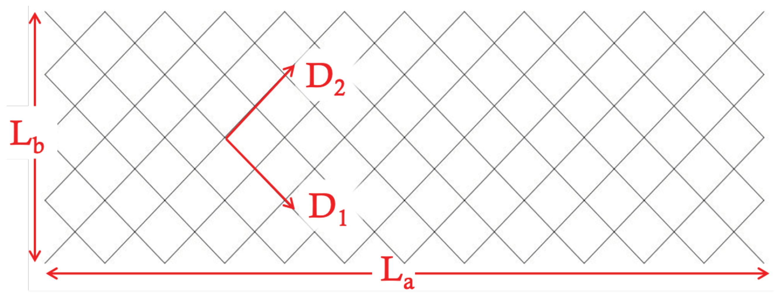
1,
12] is a 2-D representation, adequate for the description of tests that only induce in-plane deformations and stresses. Assuming a placement field that maps each point in the reference configuration to its position in the deformed configuration (see
Figure 2 for employed terminology), we introduce the orthogonal basis
on the reference configuration, with
oriented in the directions of the two families of fibers that make up the microstructure under study (see
Figure 2).
The microstructure shown in
Figure 2 can be modeled by means of a discrete model where the deformations of the fibers are written in terms of different kinds of springs. This discrete model can be then homogenized for obtaining the continuum strain energy discussed in the following. To this aim, consider a 2D continuum whose reference shape is given by a rectangular domain
, where
and
are shown in
Figure 2. Very often, it is assumed that
. This aspect ratio is generally considered everywhere in the literature on pantographic metamaterials. Its meaning is due to the fact that, when studying this kind of metamaterial, one is mainly interested in bending of fibers (this deformation, in fact, is related to second gradient of the placement field in the continuum model), and for observing a pure bending deformation, it is necessary to have at least a 1:3 ratio. In fact, considering the sample as divided in three squares, only the central one has sides that are not clamped. In the clamped extremities, important contributions due to the elongation of fibers must also be considered. Therefore, the minimal aspect ratio for observing “unclamped” bending of fibers is 1:3. If only planar motions are considered, then the current shape of the rectangle is mathematically described by a regular placement function
. By means of asymptotic homogenization of the microstructure and assuming that
is at least twice differentiable, the macroscopic strain energy obtained by homogenizing the discrete system [
1] is
where
denotes the deformation gradient
, and
. It should be remarked that the Greek indices take values in the range
. Thus, there is a first integral in Equation (
1) representing the stretching energy of the fibers (
is the stretching stiffness), whereas the second integral accounts for the bending energy of the fibers (
is the bending stiffness). Note that the bending energy is written up in terms of the gradient of the deformation tensor
that corresponds to a second gradient of the placement field
. No energy term relative to the pivots has been added to the strain energy (
1). However, in this case, the pivots are said to be perfect.
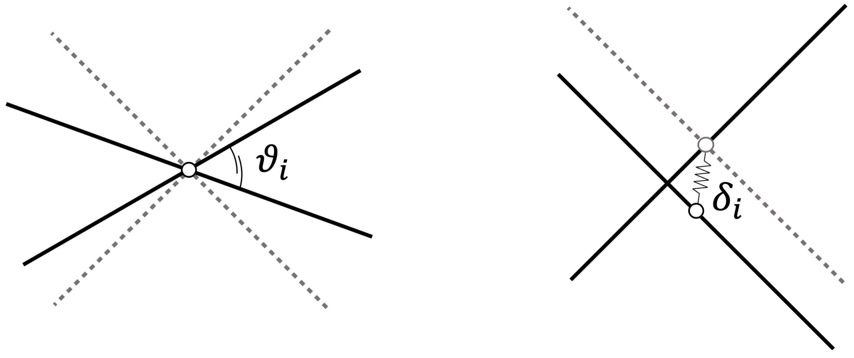
When the pivots are not obtained as perfect hinges, then one has to take into account their deformations. First, it is necessary to consider the torsion of the cylinders used to realize the pivots. An energetic term due to the torsion of the pivots can be obtained by considering the variation of the angle between the two fibers connected by a given pivot. The angle variation, in fact, corresponds to a torsion of the cylinder (see
Figure 3). Following [
1], one can express this energetic term as follows:
where, generally, the exponent
can be taken to be equal to 2. This energetic term is not able to predict all kinds of behaviors (for example, for samples manufactured in metal, it has been seen that it does not fit the experimental data correctly) but is a good compromise in a first approximation. Moreover, it has to be remarked that although it is related to the torsion of the pivots, this energetic term represents, from the macroscopic viewpoint, the shear energy of the pantographic continuum.
To summarize in a clear and concise manner, one can consider that two continua are introduced for the description of this metamaterial. These continua are related to the two introduced placement fields, employed to describe the displacements of the material points of the continua. The placement fields are defined in any point of the continua. The need to introduce two continua is related to the fact that this particular metamaterial has a microstructure that is conceivable as an assembly of two fiber families. This is a mathematical description, and a fiber in this model does not correspond to a fiber in a possible practical exemplification. The mathematical fibers are dense in the sense of a homogenization procedure. The efforts in this direction are based upon work by Pipkin and co-workers [
13] on inextensible fibers.
2-Fields vs. 1-Field Model
As previously discussed, different deformation mechanisms occur during the deformation of pantographic metamaterials. Specifically, these deformations affect the constituent elements, i.e., fibers and pivots. As far as fibers are concerned, they can basically be flexed or stretched. Specifically, it was seen in [
1] that the deformation energy term related to fiber bending is closely linked from a theoretical point of view to the second gradient of the placement field.
As has been shown, at least two types of deformation are associated with pivots: their torsion and their micro-shear. These deformations affect the fibers as relative deformations between the two parallel layers interconnected by the given pivot. In fact, the torsion of the pivot results in a change in the angle between the fibers, while the micro-shear corresponds to the sliding between such fibers (see
Figure 3).
While torsion of the pivots always occurs, unless they are made as perfect hinges, the micro-shear of the pivots is advantaged under certain conditions. In fact, the geometry of the connecting pivot determines its torsional stiffness on the one hand (greater rigidity corresponds to steeper cylinders), and its tendency to be sheared on the other. It can be established in a rather general way that slender pivots will be easier to be sheared than thicker pivots.
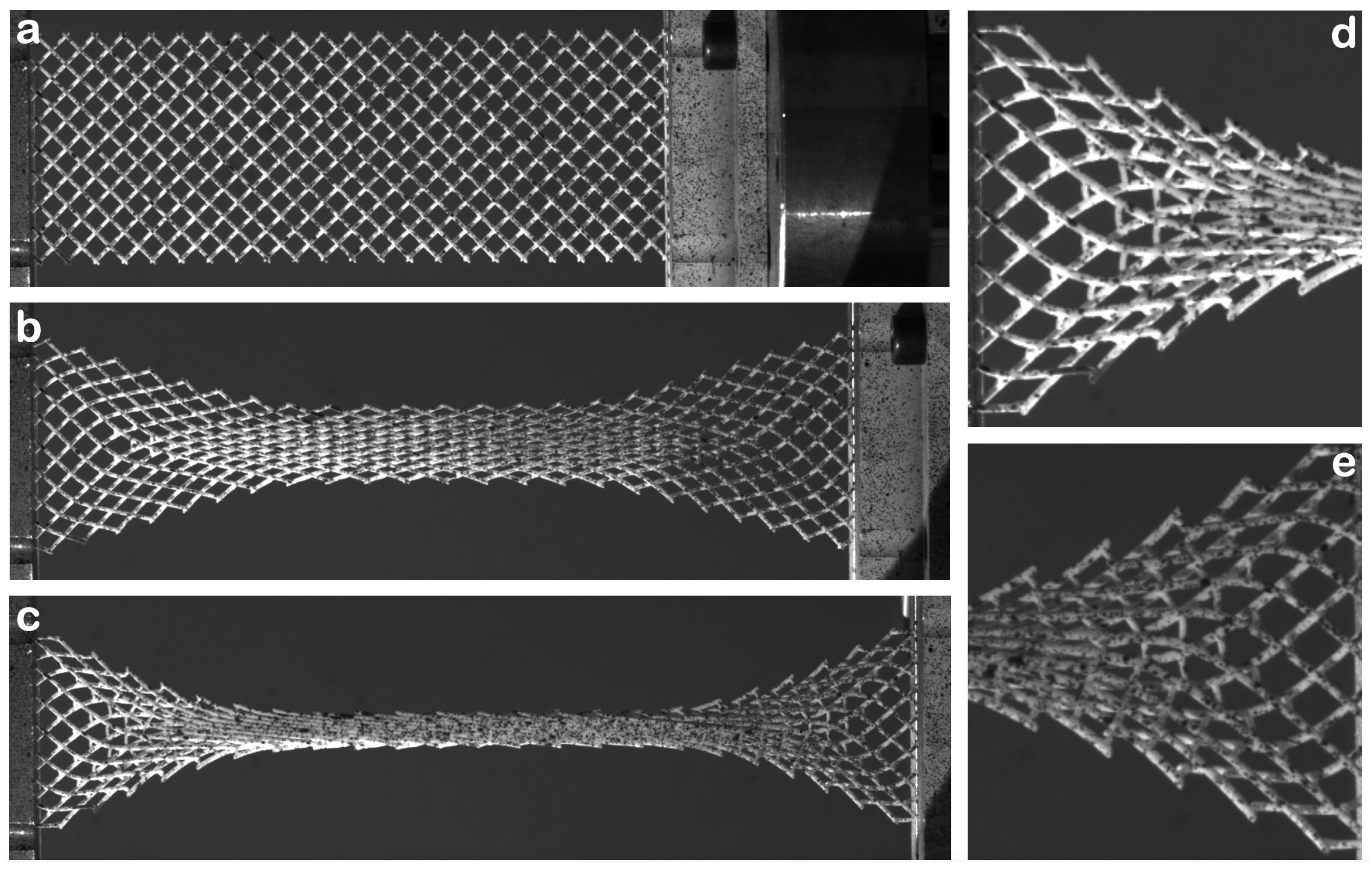
The micro-shear deformation of the pivots produces, as already stated, the relative sliding between the fibers. This can easily be observed experimentally. An example of such a deformation mechanism is given in
Figure 4.
When the micro-shear deformation of the pivots cannot be neglected, it becomes clear that the single-field model introduced previously for the description of the pantographic continuum is no longer sufficient to correctly describe the problem at hand. This model must therefore be extended. The simplest way to account for micro-shear and fiber sliding is to adopt not one but two placement fields and to introduce a coupling term. The coupling term, of course, represents a measure of the micro-shear deformation of the pivots and the ability of the fibers to slide relative to each other.
From a mathematical point of view, this coupling term can be written as
Once one has included the two fields
in Equations (
1) and (
2), it is sufficient to add
to the total to obtain a strain energy which correctly describes the pantographic continuum when micro-shear is not negligible.
In order to clearly convey the ideas presented so far, to account for the pivot shear microdeformability and the resulting sliding between the fibers of the two families, the one-field model is extended by introducing two fields in all energy terms described by Equations (
1) and (
2) and including the coupling term between the two fields presented in Equation (
3).
3. Symmetrization of Mechanical Response: Numerical Study
In this section, numerical results are presented to show the influence of the micro-shear of pivots in symmetrizing the mechanical response of a pantographic sample. The second-gradient model reported in
Section 2 has been implemented in a commercial finite element code, both in its 1-field and 2-fields versions. The constitutive parameters chosen for performing the numerical analyses are the same in the two simulations: the only difference is that in the second case, one has a stiffness
related to the coupling term modeling the micro-shear of pivots in Equation (
3).
The numerical values of all the stiffnesses are reported in
Table 1.
A first fundamental result is shown in
Figure 5, where the reaction forces relative to the two models are plotted in terms of the prescribed displacement. As is evident, in the 2-fields model, the curve (red, dashed line) is, with good approximation, symmetric with respect to the origin. This means that the micro-shear of pivots has introduced the possibility to the fiber layers to slide one with respect to the other, allowing, in the end, for a reaction force (or, equivalently, for a total strain energy) lower than in the 1-field model. Such a lowering of the reaction force is understood if one considers that the microstructure can be stretched to the same prescribed displacement, activating two different mechanisms in the two cases: in the 1-field model, the fiber elongation is activated; in the 2-fields model, on the contrary, the fiber layers are sheared, consisting of a global stretching of the microstructure. Obviously, in the second case, the fiber elongation will also be activated, but in a stage of deformation that is associated with a considerably larger prescribed displacement.
In summary,
Figure 5 gives a proof of how the sliding of fiber levels can be introduced to decrease the influence of fiber elongation in axial tests, therefore symmetrizing the global mechanical response.
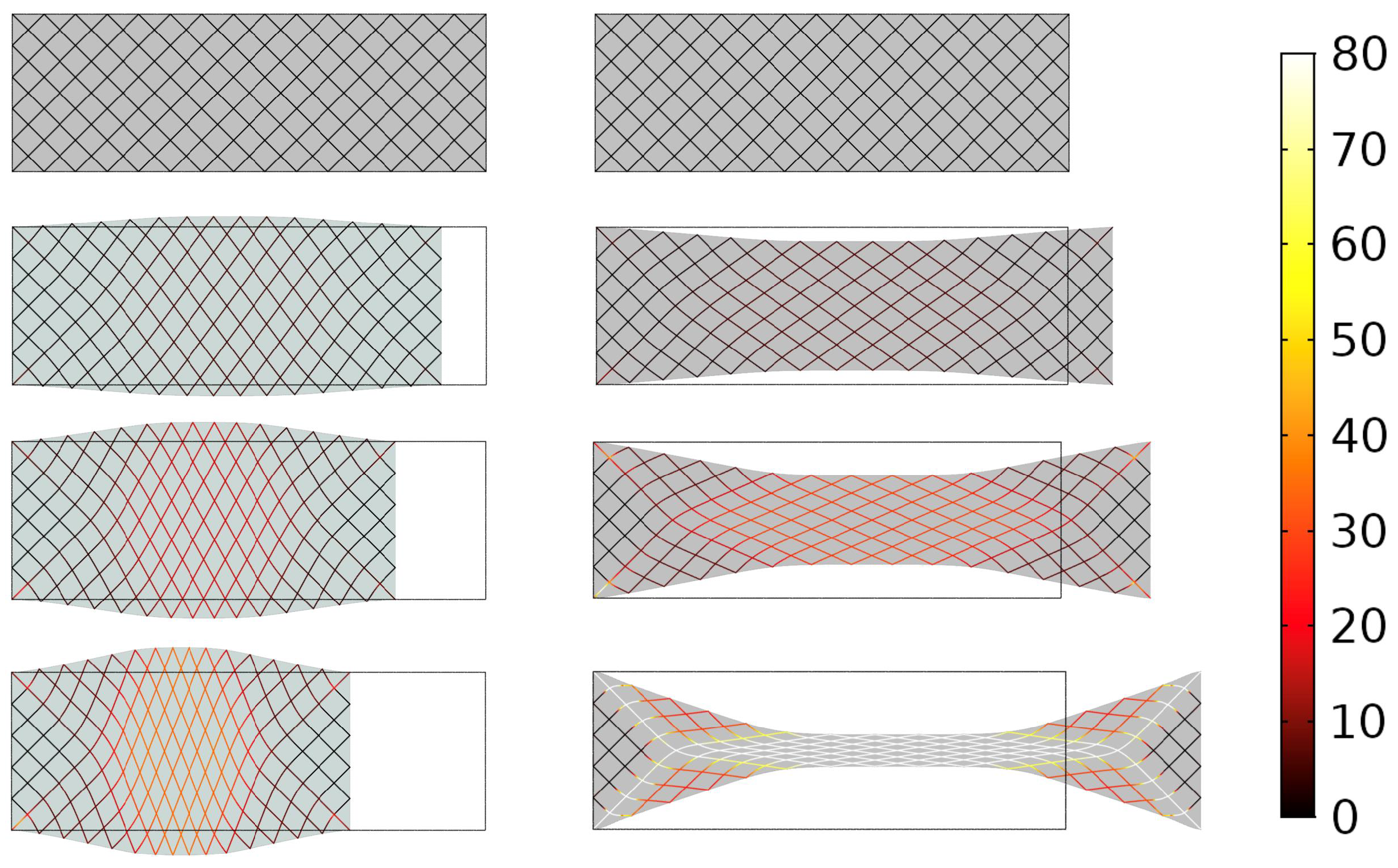
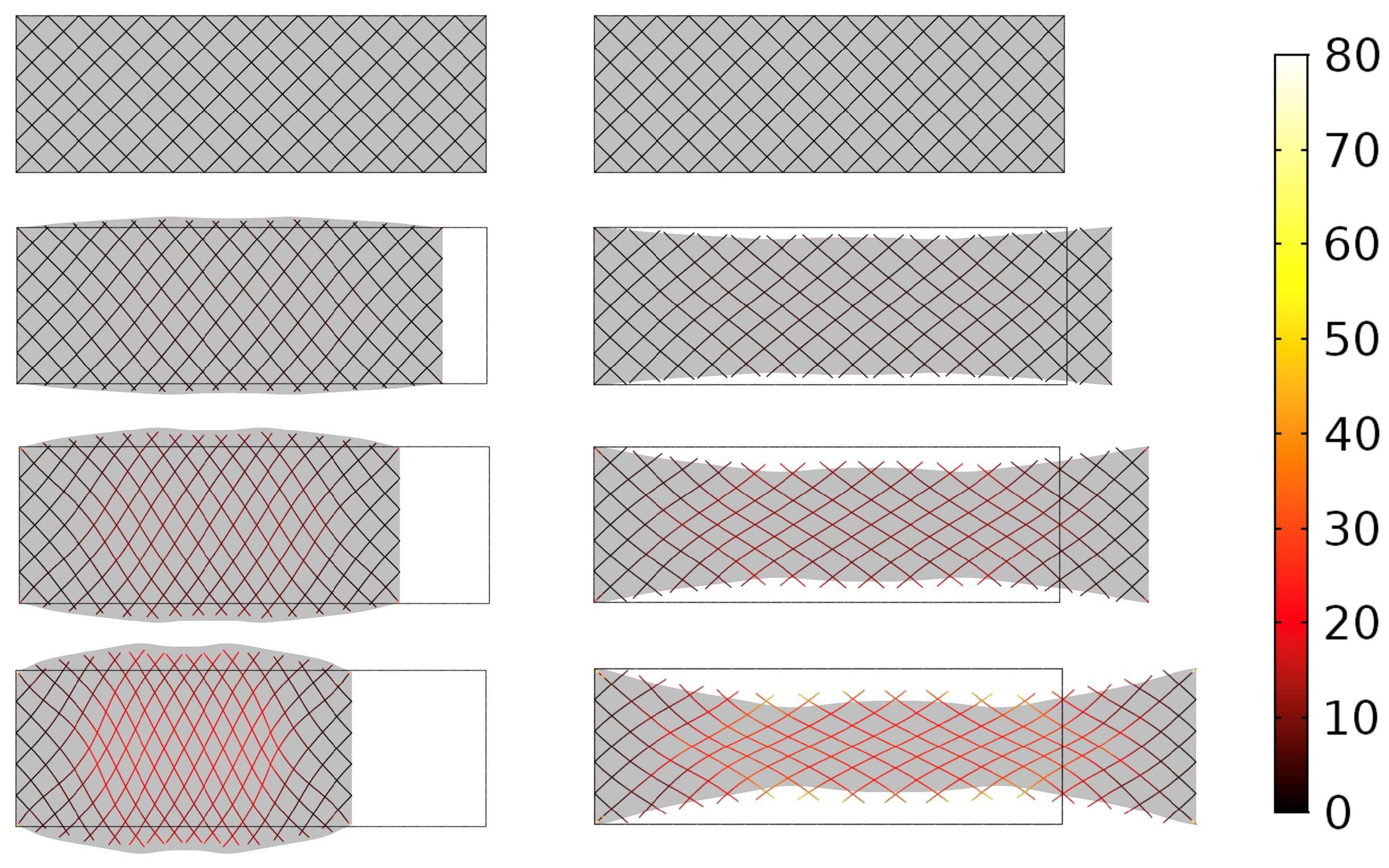
Numerical simulations also give as a result the plot of deformed shapes in the axial tests (
Figure 6 and
Figure 7). In
Figure 6, such deformed shapes are shown for the 1-field model, while the same plots are reported for the 2-fields model in
Figure 7. By comparison of the two figures, one can simply understand how the sliding of fiber levels allows for a global elongation but with no activation of fiber elongation. In fact, by referring to the last step of deformation in the stretching test for the two figures (right, bottom corner), it is evident that in
Figure 7, the fibers swiped each other. Moreover, in the 2-fields model simulations, the transverse depth of the sample proves to be larger than in the 1-field case, thus inducing less fiber elongation (which is activated when the central fibers are in contact).
It has to be remarked that in
Figure 6 and
Figure 7, the deformed shape of the continuum has been plotted in grey, while the total energy density has been plotted in the color scale only on a set of chosen fiber directions. This choice has been made to clarify the idea of fiber deformation, which, in a continuum, could be difficult to visualize.
It is noteworthy to observe that in the compression test for the 2-fields model, a sort of compression coat arises where the energy density is maximal. It could be interesting to investigate which kind of deformation would occur for different aspect ratios of the sample.
Finally, it has to be remarked that in the last step of the elongation test, the values of the energy densities are very different for the two models: this is yet another proof that in the 1-field model, the fiber elongation has been activated, while in the 2-fields model, the fibers are still not in contact.
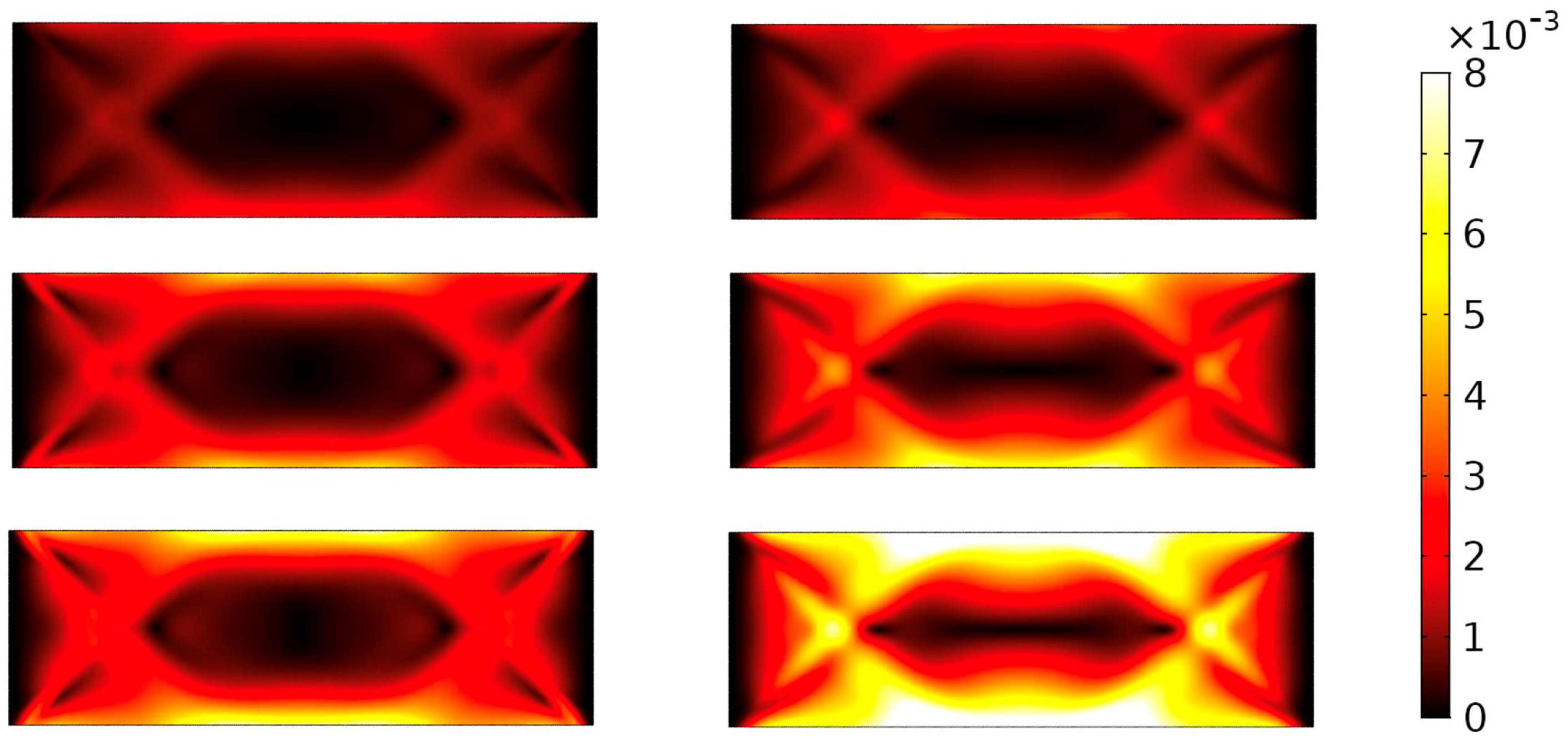
The swiping between the two fiber layers can be made clearer by plotting the modulus of the relative displacement, as in
Figure 8. Here, the absolute value
is reported in the color scale. On the left side, this value has been plotted for the compression test, while on the right side, it is reported for the extension test. Three further observations must be done relative to
Figure 8.
First, it has to be remarked that the values of relative displacement are considerably higher in the extension test (right) than in the compression test. In fact, it is evident that, at least in the first stage of deformation, both in the extension and compression tests, the relative angle between the fibers of different layers, which gives a measure of the torsion of the pivots, is the same in the modulus. This cannot be said relatively to the micro-shear of pivots. In this sense, in the range of small deformations, differently from what has been observed in the range of large deformations, the micro-shear contribution induces a breaking of symmetry. More precisely, in the first stages of deformation, the global behavior is dominated by the torsion of the pivots’ contribution and by their micro-shear (in fact, the bending of fibers contribution is the smallest one and the fiber elongation is not yet activated). As said, the torsion of pivots is symmetric in compression-extension, while a priori, the micro-shear is not. Therefore, deformation contributions act differently at different scales.
Second, the maximum observed value of relative displacement (in the last extension step) proves to be approximately 8 mm; this value must be correctly set in the experimental framework. In fact, normally, one does not produce specimens with pivots longer than a maximum of 3–4 mm. Therefore, this value of displacement would not be physically observable in an experiment (the displacement cannot be larger than the length of the pivot itself!). This means that the most sheared pivots would be broken before this value of relative displacement. These displacements could be reduced by increasing the value of
. On the other hand, one should take into account that the value of this stiffness must be calibrated on the experimental data, if available, and that, as already remarked, a very large displacement is to be considered unphysical because the considered hinge would be broken before this displacement is observed. In this sense, the plot in
Figure 8 can be used for introducing a damage criterion. This has been attempted in [
8].
Third, it is interesting to observe that on the one hand, the long sides of the rectangular continuum are micro-sheared in both extension and compression tests, and a certain similarity can be found between the two plots. On the other hand, there is one point that behaves differently: it is the vertex of the undeformed triangle (i.e., the isosceles triangle whose basis corresponds to the short side of the sample and which is mainly non-deformed in both compression and extension tests). The pivot posed in this particular point is strongly sheared in the extension test (see also
Figure 4 for an experimental example of this mechanism) and is one of the first pivots to be broken in experiments. On the contrary, in the compression test, this same pivot is approximately not sheared at all.
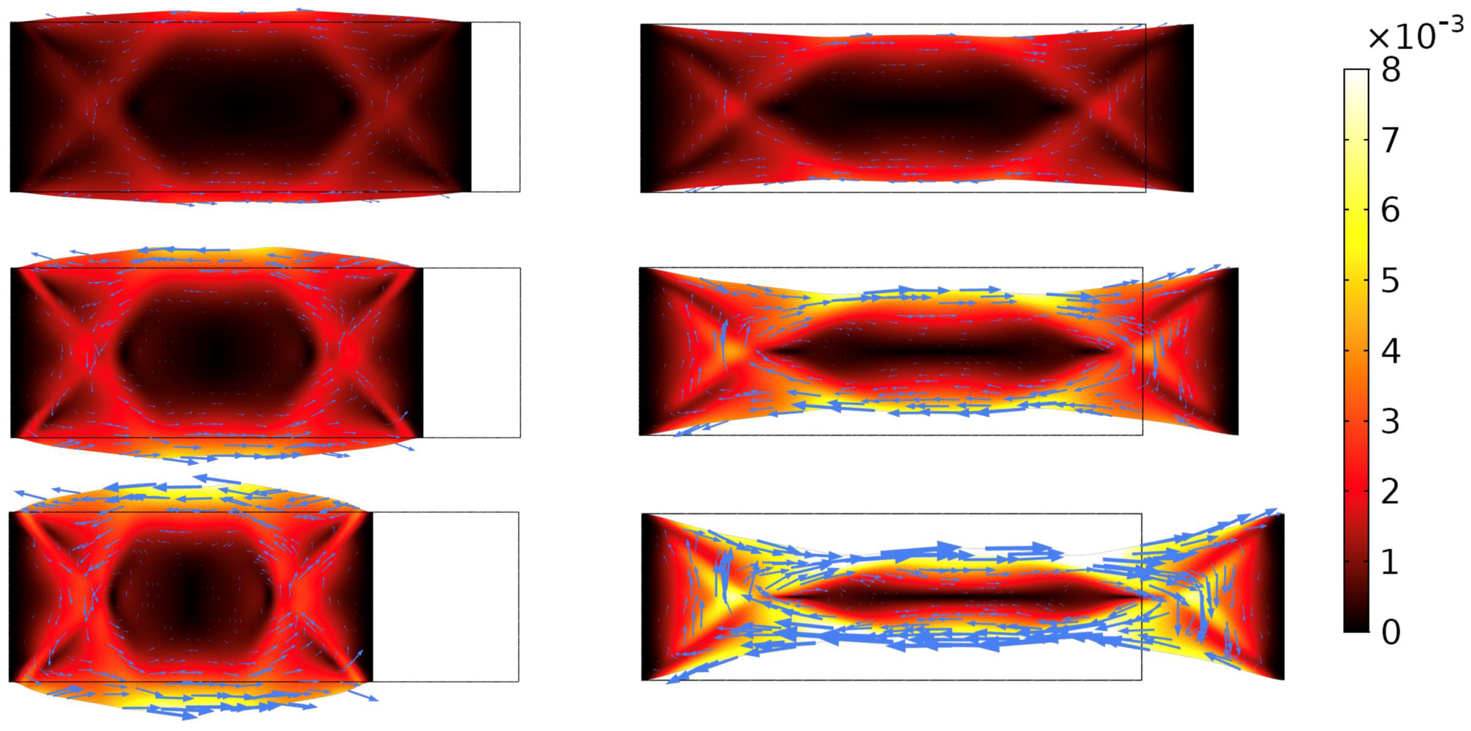
Finally,
Figure 9 reproduces the same relative displacements shown in
Figure 8 but plotted on the deformed shape of the sample and with arrows that represent the vectorial displacement of selected points of the continuum corresponding to the nodes of the mesh. The vectorial information of the displacements is of interest. In fact, one can observe that the relative displacements are in opposite directions on the opposite sides of the sample. This suggests that the micro-shearing of pivots also contributes to the macro-shear energy. Such aspect of the problem has not been yet investigated and could be approached in future works.
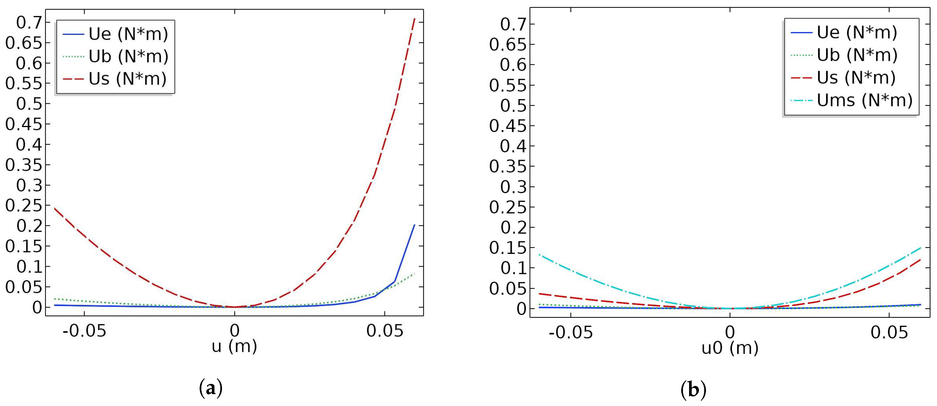
A last remark must be devoted to the different energetic component of the two models. These contribution are plotted vs. the prescribed displacement in
Figure 10a,b. In these figures, it is clearly observable that some components of the deformation energy are also non-symmetric in the 2-field model, as is natural, but their effect on the macroscopic behavior of the metamaterial is shaded by the contribution due to the micro-shear deformation.
4. Conclusions
The deformation of hinges affecting the mechanical behavior of pantographic metamaterials has been investigated. A critical role is assumed by the micro-deformation of the pivots. Macroscopically, this deformation corresponds to the sliding between the fibers of the two families that make up the metamaterial. It is shown, numerically, that bias extension and compression tests are symmetrized by the introduction of slidability between the fiber layers, i.e., the micro-shear of the pivots. However, this symmetry is lost when no micro-shear is considered and fiber elongation deformation is activated.
The study presented in this work could be improved by taking into account more details from the theoretical point of view. Useful results in the theoretical framework underlying this kind of metamaterial can be found in [
14]. As shown in [
8,
15], micro-shearing induces failure modes that were not previously observed in pantographic metamaterials. Such an observation and, in addition, the damage analysis of pantographic metamaterials, have inspired recent investigations into the optimization of these structures [
16,
17]. Several studies on the damage in materials characterized by mechanical properties, which can be studied in the framework of generalized media, can be helpful in order to improve the treatment of damage in the special example of pantographic structures. Among the published results, we refer to [
18].
The study of symmetry and symmetry breaking in metamaterials is of relevance: in the literature, there are examples of interest where symmetry breaking is shown to be important for multifield applications [
19]. The solution of such kinds of problems often requires the implementation of non-trivial computational tools. To this aim, it could be useful to refer to results already present in the literature, such as [
20,
21].


