Article

Model-Free Non-Cascade Integral Sliding Mode Control of Permanent Magnet Synchronous Motor Drive with a Fast Reaching Law

1
College of Automation, Qingdao University, Qingdao 266071, China
2
Shandong Key Laboratory of Industrial Control Technology, Qingdao 266071, China
*
Author to whom correspondence should be addressed.
Symmetry 2021, 13(9), 1680; https://doi.org/10.3390/sym13091680
Submission received: 15 August 2021 / Revised: 5 September 2021 / Accepted: 9 September 2021 / Published: 12 September 2021
(This article belongs to the Special Issue Symmetry in Power Battery Management Systems)

Abstract

:
Electric vehicle has become the main trend of the development of automobile industry. As a highly symmetrical system, the characteristics of drive motor will have a great impact on the driving comfort. Aiming at the control regulation of permanent magnet synchronous motor (PMSM) drive, a model-free and non-cascade sliding mode control with a fast-reaching law is proposed in this paper. Firstly, the mathematical model of PMSM is constructed as an ultra-local model without considering any motor parameters. Then, to improve the response speed, an integral sliding mode method with a fast reaching law is proposed, and the fast convergence can be realized. The controller system adopts single loop non-cascade control, which greatly simplifies the system structure. In order to further improve the anti-disturbance performance of the system, the dual disturbance observers are used to compensate the disturbance through feed-forward control. The stability of the system is proved by Lyapunov. Finally, the experimental results show that the proposed method has faster convergence speed and stronger anti-disturbance ability.

1. Introduction

Due to its high power, high reliability and strong practicability, permanent magnet synchronous motor (PMSM) has been widely used in the symmetrical structure with complex working condition, such as electric vehicle, robot and other industrial productions [1]. The ride quality and driving comfort of electric vehicle are closely related to the dynamic performance of motor driver system, and the electric vehicle creates a symmetrical entity with the road during operation, and its reference frame is represented by the dynamic, the control characteristics of drive motor also have the direct impact on battery performance. Commonly, the double-loop cascade control with PI approach through field-oriented control is adopted [2]. However, due to the strongly coupled nonlinear characteristics, and the influence of external uncertain factors such as load torque and parameters uncertainties, it is difficult to achieve good control performance by the common PI control method. In recent years, to improve the dynamic response and anti-disturbance performance, some advanced control algorithms have been proposed to improve the motor control performance, such as sliding mode control [3,4], model predictive control [5], model-free adaptive control [6], backstepping control [7].
Among these methods, sliding mode control, which is a kind of variable structure control [8] attracts the attention because of its fast convergence speed and robustness. However, common linear sliding mode control is difficult to achieve finite time convergence. Although terminal sliding mode control [9] can achieve finite time convergence, its convergence speed is not ideal. The integral sliding mode method accelerates the convergence rate of the system. Integral sliding mode control can eliminate the reaching phase by enforcing sliding mode throughout the whole process of system response and thus the invariance of the system to parameter variation is guaranteed starting from the initial time instant [10]. Sliding mode control is usually divided into two parts, one is sliding mode surface design and the other is reaching law control. The reaching law control is directly related to the process of reaching the sliding surface. In [11], an exponential approximation law is proposed to accelerates the convergence speed. By adding a terminal attractor to the arrival law [12], the convergence speed is effectively accelerated, but the parameter adjustment is complex. The system state variables and the power term of the sliding mode function are introduced in a new sliding mode reaching law to improves the convergence speed of the system [13].
In addition, sliding mode control can suppress the matched disturbance in the system, which means the uncertainties exist in the same channel as that of the control input [14,15]. But it is weak in suppressing the mismatched disturbance, such as the load disturbance of PMSM in non-cascade control. The disturbance rejection technique based on disturbance observer becomes an effective method to deal with the disturbance, such as disturbance observer [16], extended disturbance observer [17,18], finite time disturbance observer [19], nonlinear disturbance observer [20], sliding mode observer [21], reduced-order observer [22].
Although sliding mode control has some robustness for the disturbance, it is still a model-based control method, and the control performance has a high dependence on the motor parameters. In the process of motor operation, it is difficult to accurately know the motor parameters. Recently, the model-free control has aroused wide attention. It is based on the ultra-local model, which is established by the input and output of the system [23]. The technology does not depend on the parameters of the control system, and it has been used in parking system [24], robot [25], PMSM [26]. In [27], a model-free predictive current control method based on an ultra-local model is proposed for PMSM. This method only uses the input and output of the system without considering any motor parameters. The model-free adaptive integral sliding mode is applied to PMSM to achieve a good speed tracking effect [6]. In [28], a non-cascaded model-free predictive speed control of PMSM is proposed to achieve fast dynamic response.
In this paper, a model-free non-cascade integral sliding mode control of permanent magnet synchronous motor drive with a fast reaching law is proposed. The experimental results show that the proposed method has fast convergence and good anti load disturbance ability. The main contributions are as follows:
(1) A fast sliding mode reaching law is proposed for PMSM drive to improve the convergence rate.
(2) By introducing model-free control, the model is simplified and the dependence on motor parameters is avoided.
(3) By combining the proposed sliding mode control method, the dual disturbance observers are designed to further improve the anti-disturbance ability of the drive system.
This article is organized as follows. In Section 2, the model-free mathematical model of permanent magnet synchronous motor is presented. The design of double disturbance observers is introduced in Section 3. Section 4 describes the design of non-cascade integral sliding mode control with a fast reaching law. Experiments are verified in Section 5. Conclusion is followed in Section 6.

2. Ultra-Local Model of PMSM

The mathematical model of permanent magnet synchronous motor in the d-q axis rotor coordinate system can be expressed as [29,30]
d i d d t = R s i d + n p ω L q i q L d + u d L d + f d d i q d t = R s i q n p ω L d i d L q n p ω Φ L q + u q L q + f q d ω d t = n p [ ( L d L q ) i d i q + Φ i q ] J B J ω + f ω
where L d , L q are d-axis and q-axis stator inductances, i d and i q are the stator current, u d and u q are stator voltage, R s is the stator resistance, n p is the number of pole pairs, Φ is the rotor flux, J is the inertia, B is the coefficient of friction, ω is the mechanical angular speed. f d , f q , f ω represent the disturbance caused by parameters variation, model uncertainties and external load disturbance, which are considered as bounded and change slowly during motor operation.
The electromagnetic torque is
T e = n p [ ( L d L q ) i d i q + Φ i q ]
For surface PMSM, the d-axis inductance is equal to the q-axis inductance ( L d = L q ) and the electromagnetic torque can be expressed T e = n p Φ i q . From the third equation in Equation (1), which can be simplified as
d ω d t = n p Φ i q J B J ω + f ω
According to the reference [23], the second and third expressions in the motor model (1) can be rewritten as
d i q d t = ( 1 L q α 1 ) u q + R s i q n p ω L d i d n p ω Φ L q + f q + α 1 u q d ω d t = ( n p Φ J α 2 ) i q B J ω + f ω + α 2 i q
where α 1 , α 2 are proportional adjustable factors, and the selection of parameters will affect the motor control performance. Then (4) can be rearranged as an ultra-local model
i ˙ q = α 1 u q + F q ω ˙ = α 2 i q + F ω
where F q = ( 1 L q α 1 ) u q + R s i q n p ω L d i d n p ω Φ L q + f q and F ω = ( n p Φ J α 2 ) i q B J ω + f ω are lumped disturbances including parameter uncertainties and external unknown disturbances.
Define the speed error e as
e = ω r ω
where ω r and ω are desired speed and actual speed.
Define the state variables as x 1 = e , x 2 = α 2 i q . Then, the derivation of x 1 and x 2 can be expressed as
x ˙ 1 = ω ˙ r ω ˙ = α 2 i q F ω + ω ˙ r
x ˙ 2 = α 2 ( α 1 u q + F q )
Then, (7) and (8) can be rewritten as
x ˙ 1 = x 2 + d 1 x ˙ 2 = α 3 u q + d 2
where d 1 = F ω + ω ˙ r , α 3 = α 2 α 1 and d 2 = α 2 F q . d 1 and d 2 are matched disturbance and mismatched disturbance, respectively. Assumed that the disturbance is bounded and changed slowly in the system [31,32], thus the boundary of the disturbances in PMSM can be expressed as d 1 D 1 , d ˙ 1 D 11 , and d 2 D 2 , d ˙ 22 D 22 , where D 1 , D 11 , D 2 , D 22 are positive.

3. Design of Dual Disturbance Observers

Consider the uncertainty of the motor parameters and the influence of the load torque, in order to improve the anti-disturbance ability of the system, according to the principle of observer [33], the dual disturbance observers are designed to estimate the matched and mismatched disturbance in the system.

3.1. Design of Matched Disturbance Observer

The estimation of d 2 can be designed as
d ^ 2 = p 1 + l 1 x 2 p ˙ 1 = l 1 ( α 3 u q + d ^ 2 )
where d ^ 2 is the estimate of d 2 , p 1 is an internal variable, and l 1 is positive.
Proof 
The estimation error is defined as ε 1 = d 2 d ^ 2 and the derivation of the estimation error can be expressed as
ε ˙ 1 = d ˙ 2 d 2 ^ ˙ = d ˙ 2 l 1 ε 1
Let V 1 = 1 2 ε 1 2 , and derivation of V 1 can be obtained as
V ˙ 1 = d ˙ 2 ε 1 l 1 ε 1 2
Considering that the motor parameters change slowly in operation, assumed d ˙ 2 0 , and V ˙ 1 0 , the observer is asymptotically stable. □

3.2. Design of Mismatched Disturbance Observer

For the mismatched disturbance d 1 in (9), the following disturbance observer can be designed as
d ^ 1 = p 21 + l 21 x 1 p ˙ 21 = l 21 ( x 2 + d ^ 1 ) + d ^ ˙ 1 d ˙ ^ 1 = p 22 + l 22 x 1 p ˙ 22 = l 22 ( x 2 + d ^ 1 )
where p 21 , p 22 are internal variable, l 21 , l 22 are observer parameters and they are positive.
Proof 
Define
ε ˜ 2 = d ˜ 1 d ˙ ˜ 1 T
d ˜ 1 = d 1 d ^ 1
d 1 ˙ ˜ = d ˙ 1 d 1 ˙ ^
where d ˜ 1 is the estimation error of d 1 , d ˙ ˜ is the estimation error of d ˙ 1 . The derivative of d ˜ 1 is obtained by combined (13)
d 1 ˜ ˙ = d ˙ 1 d 1 ^ ˙ = d ˙ 1 l 21 d 1 ˜ d 1 ^ ˙ = l 21 d ˜ 1 + d 1 ˙ ˜
Similar, d 1 ˙ ˜ ˙ can be expressed as
d 1 ˙ ˜ ˙ = d ¨ 1 d 1 ˙ ^ ˙ = d ¨ 1 l 21 d ˜ 1
The error dynamic equation of the observer can be expressed as
ε 2 ˜ ˙ = D ε ˜ 2 + E d ¨ 1
D = l 21 1 l 22 0 E = 0 1
Considering that the disturbance changes slowly and bounded, d 1 D 1 , d ˙ 1 D 11 , d ¨ 1 0 . Because the observer parameters l 21 and l 22 are positive, according to Helviz’s theorem, the observer is asymptotically stable. □

4. Design of Non-Cascade Integral Sliding Mode Control with a Fast Reaching Law

In order to realize the fast-tracking performance of PMSM, an integral sliding mode control with a fast sliding mode reaching law is designed in this part. The control block diagram is shown in Figure 1. In the traditional cascade control, the controller parameters should be tuned separately from the inner to the outer loop. And to avoid ringing and large overshoots, bandwidth of cascade controllers is often limited [34,35]. In this paper, the proposed non-cascade control method can effectively simplify the system structure and reduces the control periods between the speed loop and the current loop [36].
Firstly, an integral sliding surface is designed as [37]
s = e ˙ + α e + β e ( τ ) d τ
where α , β are positive. Then, take the derivate of Equation (21) and combined (9)
s ˙ = α 3 u q + d 2 + d ˙ 1 + α ( x 2 + d 1 ) + β e
In order to realize the sliding mode control, the common exponential reaching law is
s ˙ = m 1 sgn ( s ) m 2 s
where m 1 , m 2 are positive. The common exponential reaching law can only guarantee the faster convergence, when the sliding states are near to the sliding mode surface. A fast reaching law proposed with reference to [13]
s ˙ = k 1 sgn ( s ) k 2 s k 3 s b sgn ( s 1 ) s
where k 1 , k 2 , k 3 are positive. When the system is far away from the sliding mode surface, and s > 1 , the sliding mode surface can be simplified as s ˙ = k 1 k 2 s k s b s , its convergence speed is obviously faster than the common exponential reaching law. When s < 1 , k 1 sgn ( s ) k 2 s k 3 s b sgn ( s 1 ) s become k 1 sgn ( s ) k 2 s k s b s , similarly, the convergence speed is also faster than the common exponential reaching law. In conclusion, the fast reaching law has faster convergence speed.
Combined (22) and (24), the sliding mode control law can be derived as
u q = k 1 sgn ( s ) k 2 s k 3 s b sgn ( s 1 ) s d 2 d ˙ 1 α ( x 2 + d 1 ) β e α 3
The above formula contains the amount of disturbances d 1 and d 2 , which are replaced by the estimated value of disturbance. The control law can be rewritten as
u q = k 1 sgn ( s ) k 2 s k 3 s b sgn ( s 1 ) s d ^ 2 d ˙ ^ 1 α ( x 2 + d ^ 1 ) β e α 3
Let V = 1 2 s 2 , assumed that ( d ^ 2 d 2 ) C 2 , ( d ˙ ^ 1 d ˙ 1 ) C 11 , ( d ^ 1 d 1 ) C 1 , and C 1 , C 11 , C 2 are positive, the derivative of V ˙ is obtained by combined (9), (21) and (26)
V ˙ = s s ˙ = s ( e ¨ + α e ˙ + β e ) = s ( α 3 u q + d ˙ 1 + d 2 + α ( x 2 + d 1 ) + β e ) = s ( k 1 sgn ( s ) k 2 s k 3 s b sgn ( s 1 ) s ( d ^ 2 d 2 ) ( d ˙ ^ 1 d ˙ 1 ) α ( d ^ 1 d 1 ) ) k 2 s 2 k 3 s b sgn ( s 1 ) s 2 + ( C 2 + C 11 + α C 1 k 1 ) s
when k 1 satisfies C 2 + C 11 + α C 1 k 1 , V ˙ 0 , so the system is asymptotically stable.

5. Experimental Results and Analysis

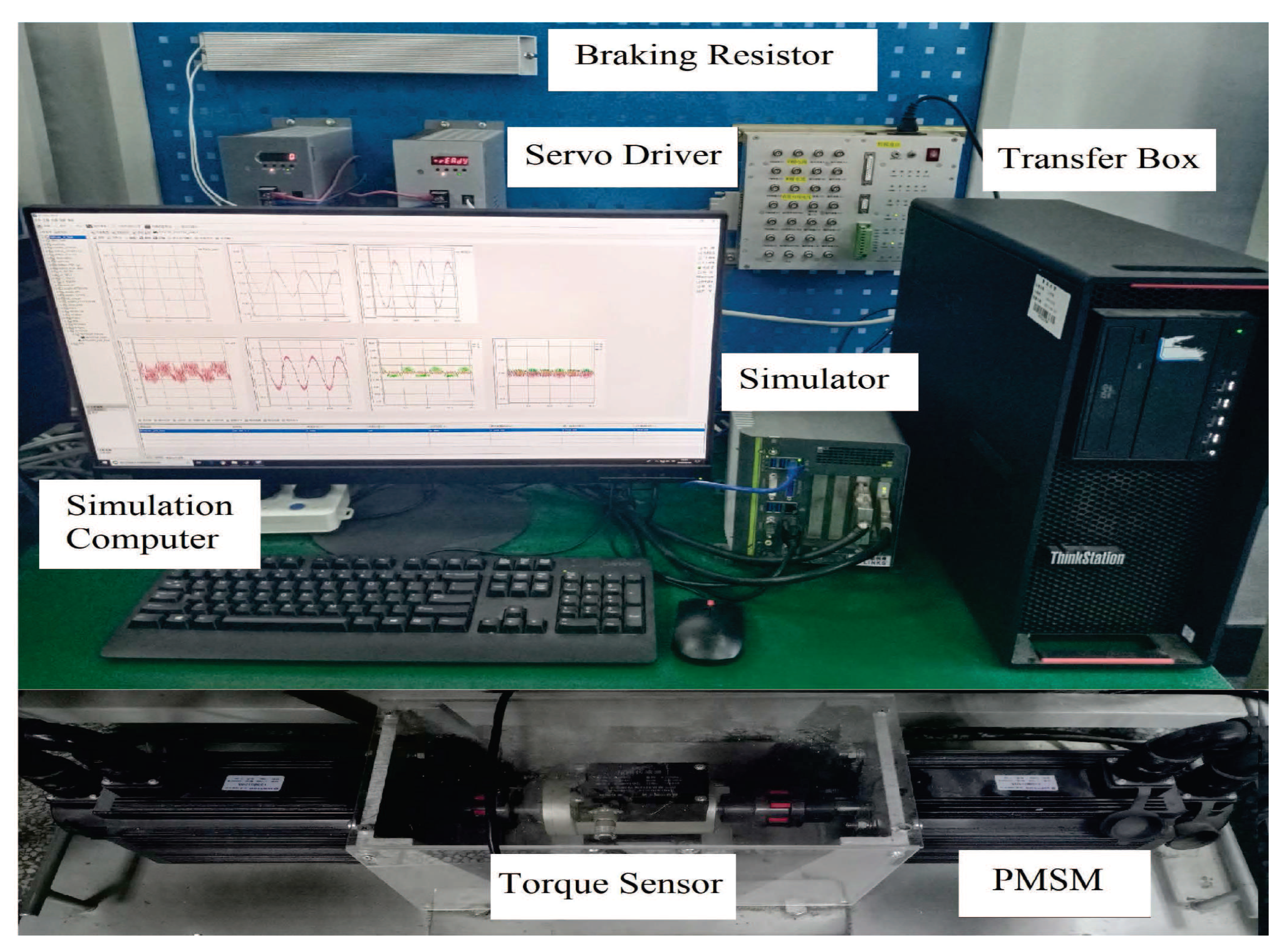
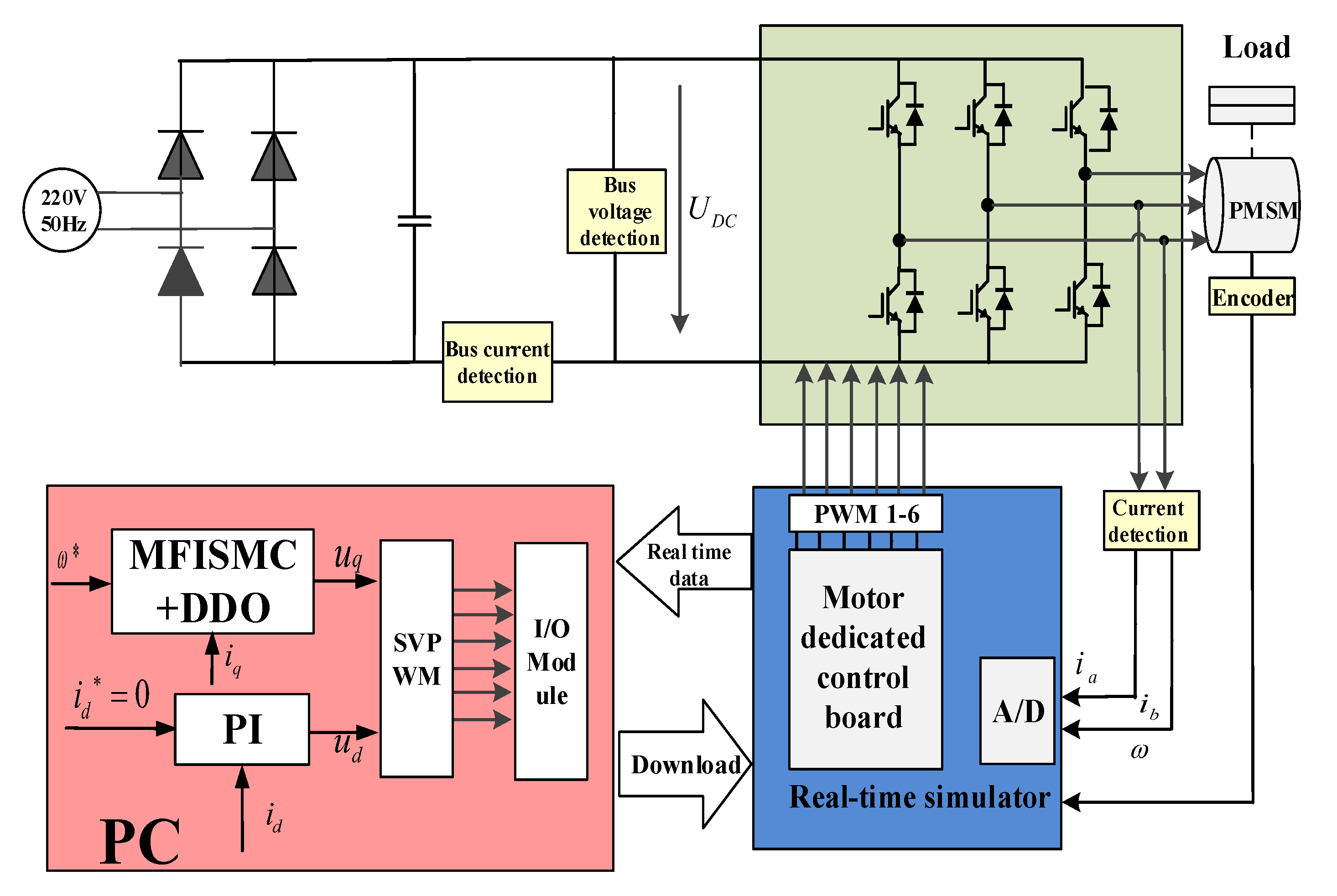
In order to verify the effectiveness of the proposed model-free non-cascade integral sliding mode control of PMSM with the fast reaching law, the experiments are carried out in this section. In this experiment, a 130MB150A non-salient pole permanent magnet synchronous motor drive system is taken as an example. The experimental platform is shown in the Figure 2. The configuration of experimental system is shown in the Figure 3. The switching frequency of the IGBT is chosen as 10 kHz. After building the MATLAB/Simulink of the simulation host, the control algorithm is compiled into the object code. Then, it is downloaded to the target computer to run through the RT-SIM software. The PMSM is controlled through a special control card, so that the control performance of the proposed method can be verified conveniently in real time. The motor parameters are shown in Table 1.
In order to verify the fast-tracking performance of MFISMC + DDO, the proposed method is compared with PI controller and integral sliding mode control with exponential reaching law based on disturbance observers (ISMC+ DDO) in the experiment. In the PI control, the parameters of the speed loop are selected as K p = 0.04 , K i = 0.5 , and the two current loops are selected for the same parameters as K p = 9 , K i = 100 . In order to reduce chattering, b, k 3 are selected with smaller parameters. To ensure the faster convergence rate, k 2 , α , β are selected with larger parameters in the controller, and larger parameters will cause corresponding overshoot. Especially if the value of β is too large, it will cause a large overshoot. In order to alleviate the above problems, the parameters of the observer can alleviate the problem of excessive parameter selection of the controller to a certain extent. At the same time, the larger parameters of the observer can reduce the speed drop and accelerate the recovery time of the speed drop. In order to weigh the effects of fast convergence, speed overshoot, chattering and anti-disturbance, the parameters are obtained by trial and error method. The corresponding parameters are l 1 = 25 , l 21 = 2 , l 22 = 30 , b = 0.5 , k 1 = 100 , k 2 = 500 , k 3 = 20 , α = 450 , β = 10 . The system has obtained fascinating control effect through the final parameter selection.
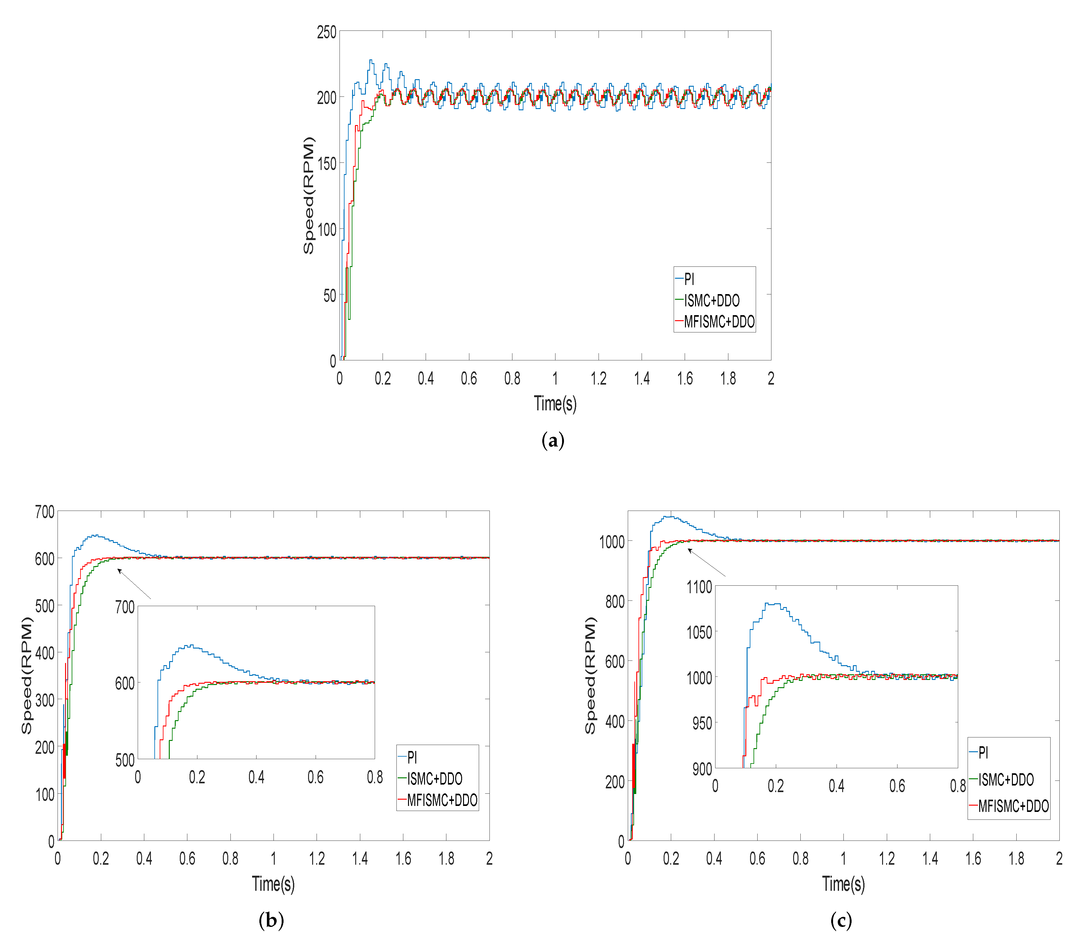
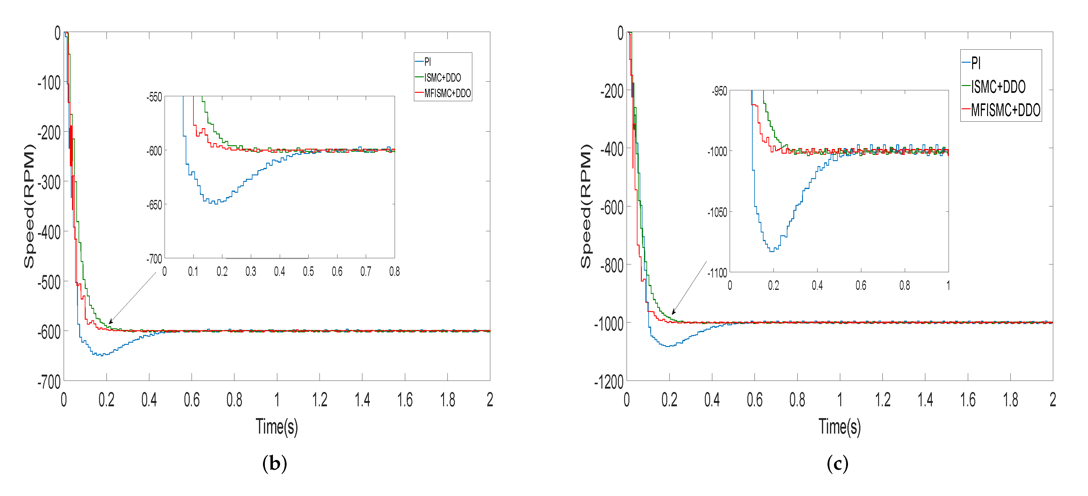
In the process of motor starting, the load torque is 0.5 Nm. The reference speed is given as 200 RPM, 600 RPM and 1000 RPM. The speed waveforms with three methods are shown in Figure 4. It can be seen from the Figure 4 that ISMC + DDO and MFISMC + DDO methods almost have no overshoot. The overshoot of PI method with 200 RPM, 600 RPM and 1000 RPM is 28 r, 48 r, 81 r, respectively. The response time of PI, ISMC + DDO and MFISMC + DDO method at 200 RPM is 0.50 s, 0.27 s, 0.20 s, respectively. And the response time of the three methods at 600 RPM is 0.56 s, 0.29 s, 0.23 s, respectively. Similarly, the response time of the three methods at 1000 RPM is 0.58 s, 0.32 s, 0.23 s, respectively. It can be seen from the experimental results that MFISMC + DDO method has the smaller overshoot and faster response speed under different speed.
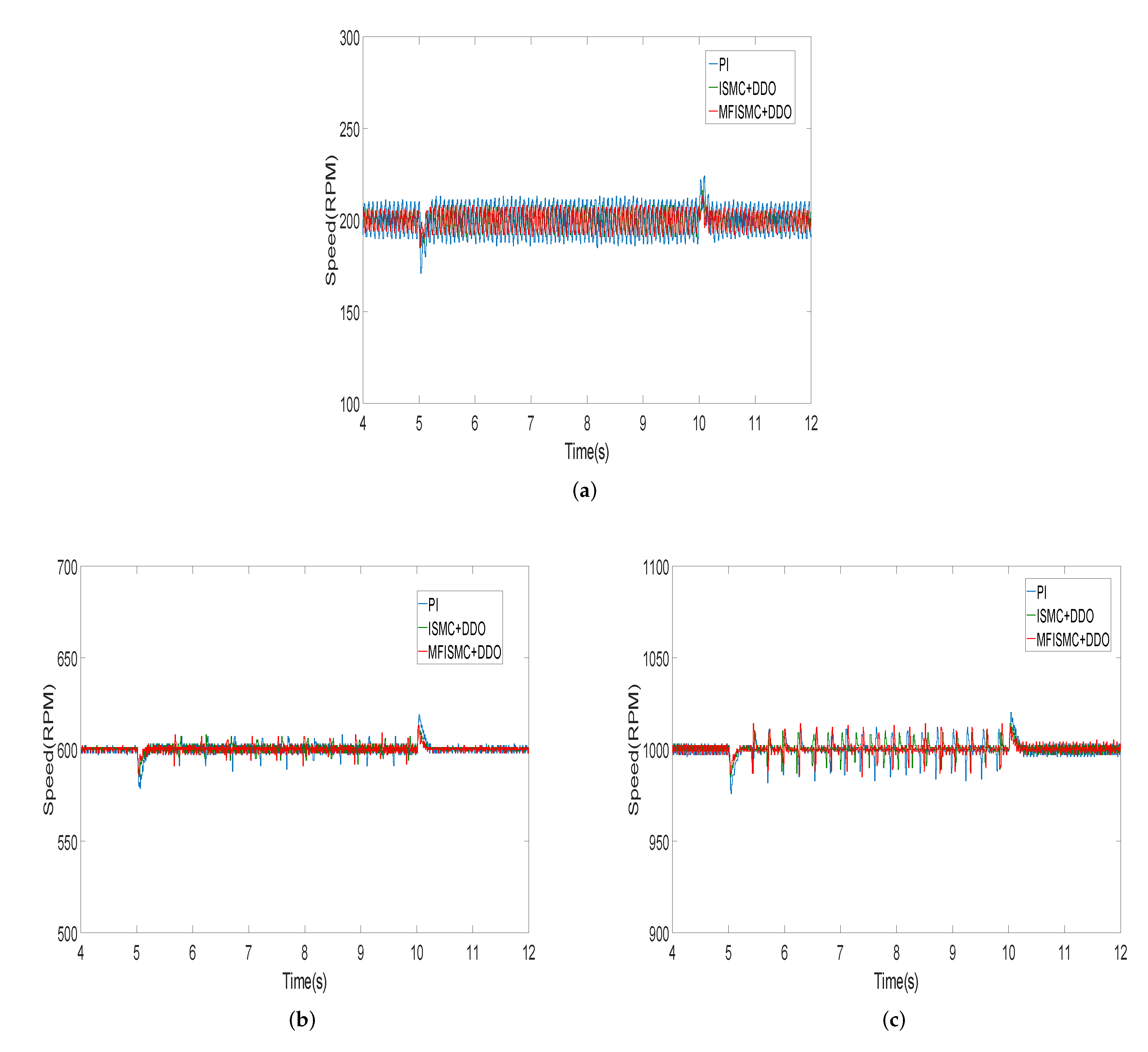
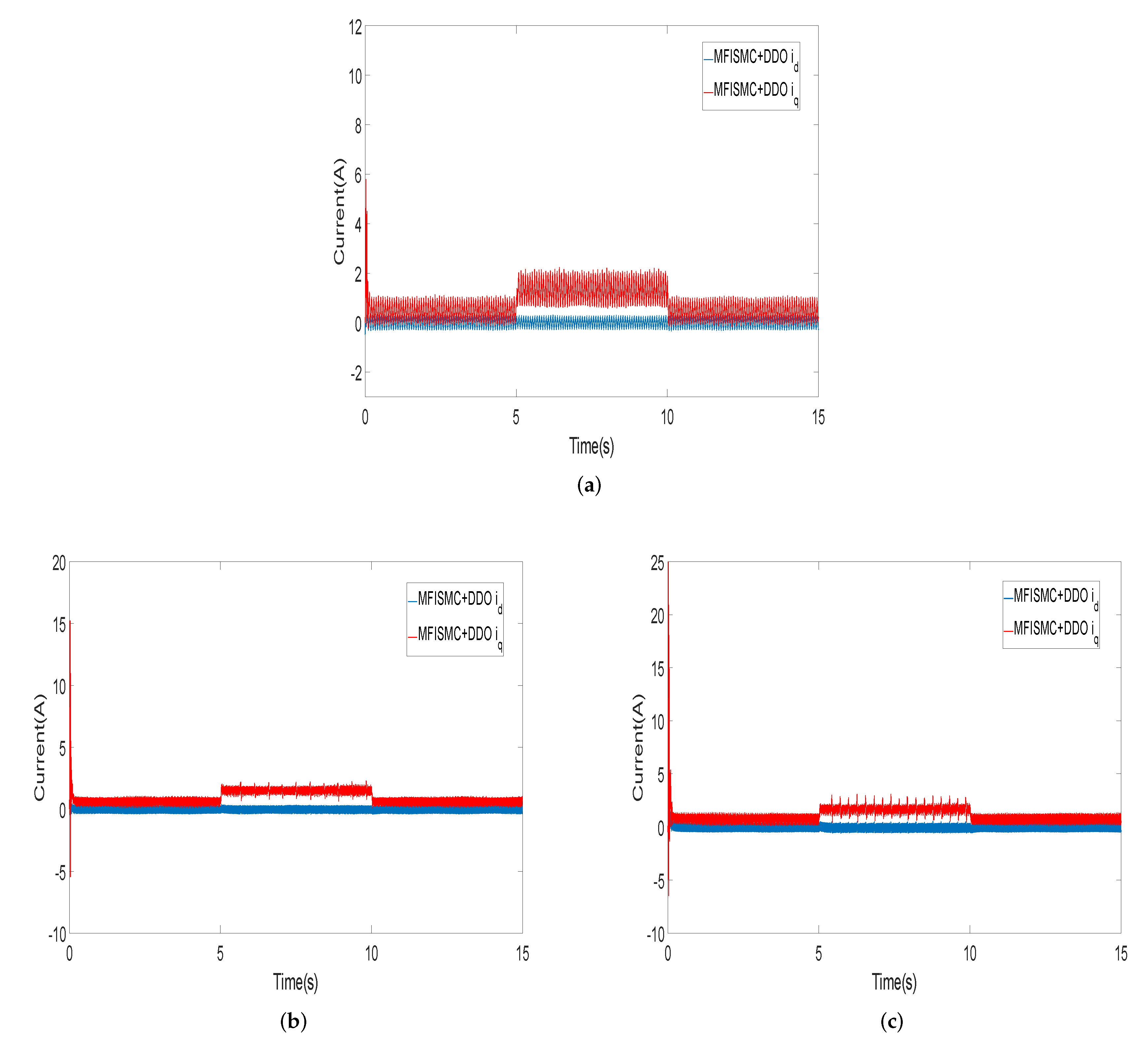
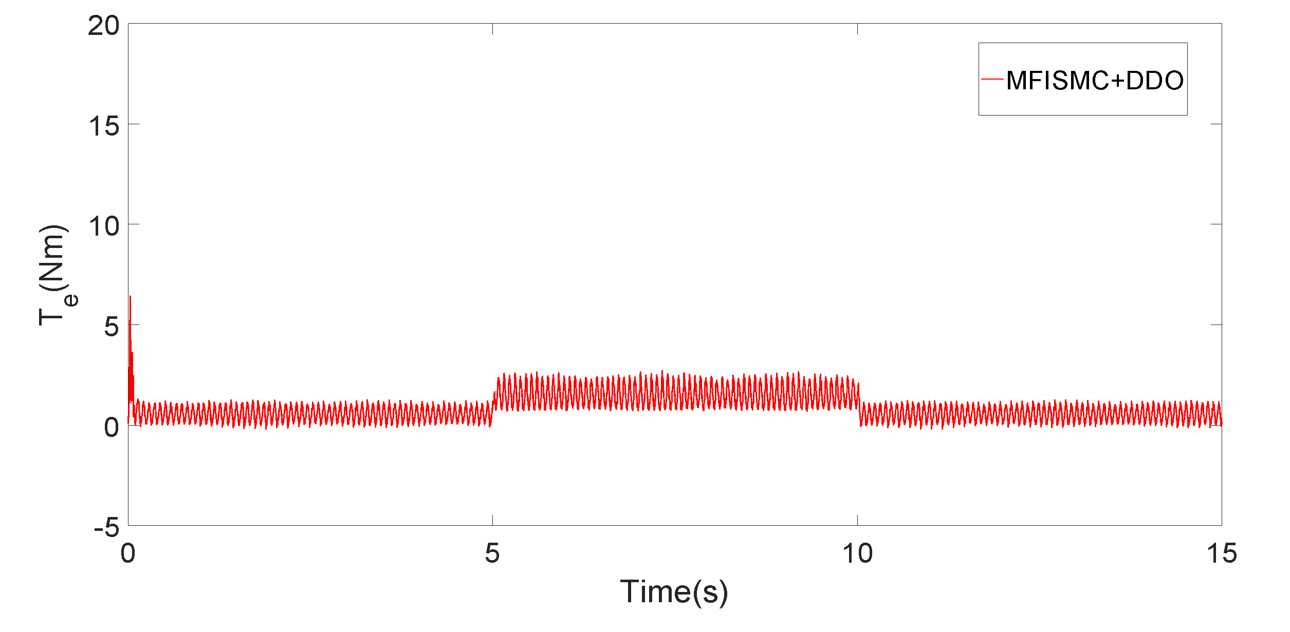
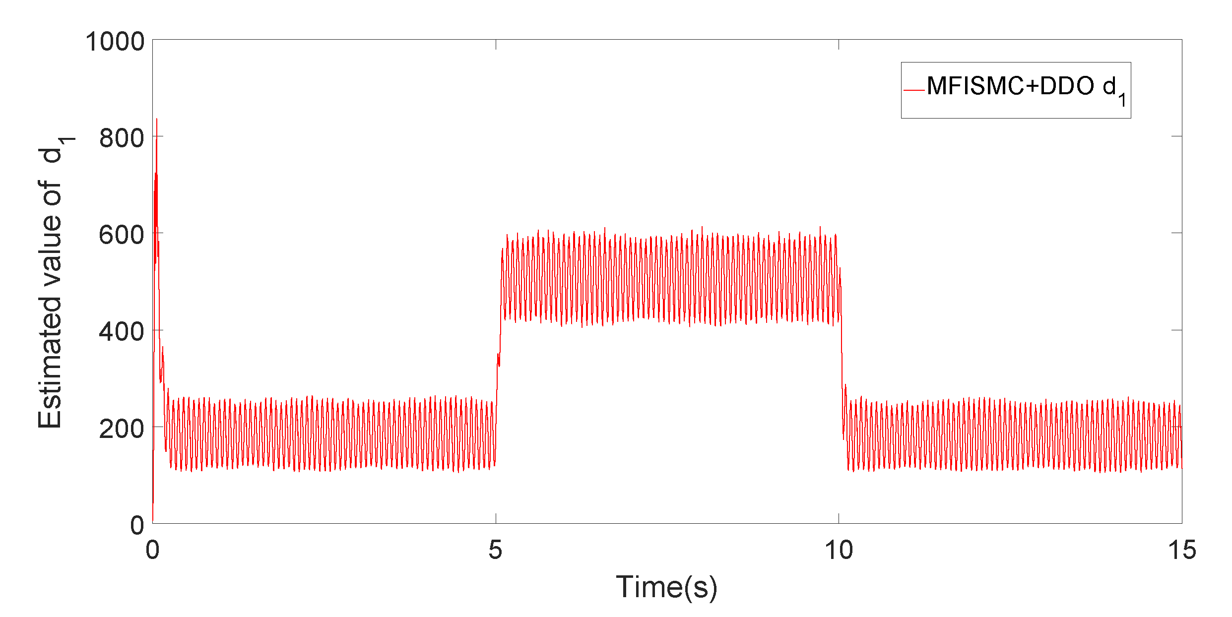
In order to verify the anti-disturbance performance of the proposed method, the following experiments are carried out. The 1 Nm load disturbance is added to the PMSM at 5 s, and the load torque is removed at 10 s. The experimental results are shown in the Figure 5. The dq-axis current waveform of MFISMC + DDO method at different speeds is shown in Figure 6. The electromagnetic torque curve of MFISMC+DDO method is shown in Figure 7. Estimated value of d 1 is shown in Figure 8. In Figure 5, taking 1000 RPM as an example, the speed fluctuation and response time of MFISMC + DDO, PI and ISMC + DDO methods at 5 s are 13 r, 24 r, 15 r, and 0.20 s, 0.28 s, 0.23 s. At 10 s, the speed fluctuation and response time of the three methods are 14 r, 20 r, 14 r and 0.19 s, 0.24 s, 0.21 s. The experimental results show that the proposed MFISMC + DDO method has the faster recovery speed and the smaller speed fluctuation under load disturbance. The speed fluctuation and recovery time under other reference speed are shown in Table 2. The experimental results show that the proposed method has better anti-disturbance performance.
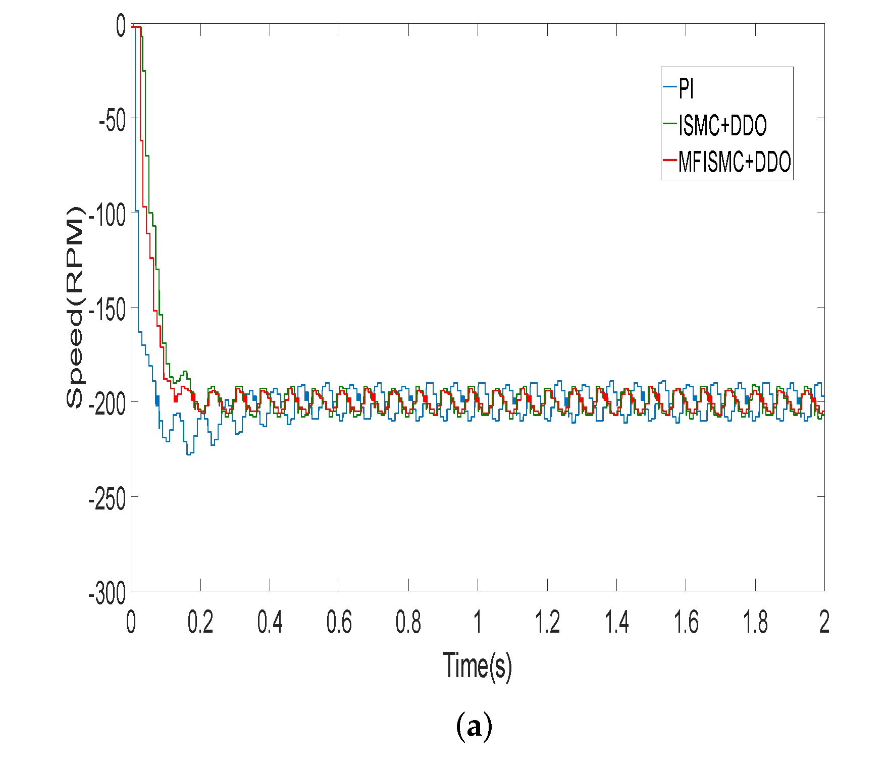
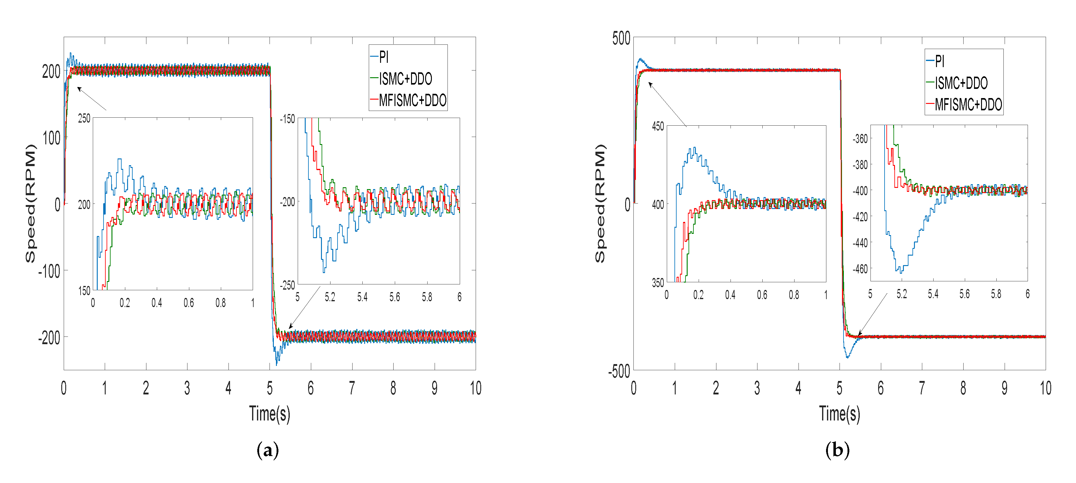
In order to test the reversal performance of the proposed method, the reverse experiment is carried out. The reversal experiment is to verify the control effect of the proposed method when reversing and changing from positive to reverse. First, the reversal experiments with −200 RPM, −600 RPM and −1000 RPM are carried out. The experimental results are shown in the Figure 9. From the experimental results, the response speed and overshoot of reverse rotation are basically the same as those of forward rotation. The reverse start performance of MFISMC + DDO method is better than that of PI and ISMC + DDO methods. This effectively proves that the proposed method also has a good control effect during reversal. In order to further verify the reversal performance of the proposed method during operation, the experiments from forward rotation to reverse rotation are also carried out. When the motor runs at 200 RPM and 400 RPM, respectively, the speed is changed to −200 RPM and −400 RPM at 5 s. The experimental results are shown in Figure 10. The experimental results also show that the overshoot and response time of the MFISMC + DDO method are better than that of the PI and ISMC + DDO methods. It is proved that the proposed method also has excellent performance in inversion.
The experimental results show that the proposed MFISMC + DDO method has fast convergence speed, small overshoot and strong anti-load disturbance ability.

6. Conclusions

In this paper, a model-free non-cascade integral sliding mode control with a fast reaching law is proposed for the speed regulation of PMSM drive. The fast reaching law effectively improves the convergence speed of the system. The model-free design greatly simplifies the system model. Through the model-free design, the dependence on the parameter uncertainty is effectively reduced. In view of the influence of external mismatched disturbances such as load torque changes, the system disturbances can be effectively estimated by the dual disturbance observers. The estimated disturbances are used for the feedforward compensation, which effectively improves the anti-load disturbance ability of the system. The experimental results verify that the proposed method has small overshoot, fast convergence speed and excellent resistance to load disturbance.

Author Contributions

T.L. completed all the experiments and wrote the manuscript, X.L. designed the proposed control strategy and conceived the structure of the paper. Both authors have read and agreed to the published version of the manuscript.

Funding

This research was funded by the National Natural Science Foundation of China under Grant No.61703222 and No.52037005, in part by the China Postdoctoral Science Foundation under Grant No.2018M632622, in part by the Science and Technology Support Plan for Youth Innovation of Universities in Shandong Province under Grant No. 2019KJN033.

Institutional Review Board Statement

Not applicable.

Informed Consent Statement

Not applicable.

Data Availability Statement

Not applicable.

Acknowledgments

This research was funded by the National Natural Science Foundation of China under Grant No. 61703222 and No.52037005, in part by the China Postdoctoral Science Foundation under Grant No.2018M632622, in part by the Science and Technology Support Plan for Youth Innovation of Universities in Shandong Province under Grant No. 2019KJN033.

Conflicts of Interest

The authors declare no conflict of interest.

References

  1. Cai, B.; Zhao, Y.; Liu, H.; Xie, M. Data-Driven Fault Diagnosis Methodology in Three-Phase Inverters for PMSM Drive Systems. IEEE Trans. Power Electron. 2017, 32, 5590–5600. [Google Scholar] [CrossRef]
  2. Yan, Y.; Wang, S.; Xia, C.; Wang, H.; Shi, T. Hybrid Control Set-Model Predictive Control for Field-Oriented Control of VSI-PMSM. IEEE Trans. Energy Convers 2016, 31, 1622–1633. [Google Scholar] [CrossRef]
  3. Liu, X.; Yu, H. Continuous adaptive integral-type sliding mode control based on disturbance observer for PMSM drives. Nonlinear Dyn. 2021, 104, 1429–1441. [Google Scholar] [CrossRef]
  4. Xu, W.; Jiang, Y.; Mu, C. Novel Composite Sliding Mode Control for PMSM Drive System Based on Disturbance Observer. IEEE Trans. Appl. Supercond. 2016, 26, 1–5. [Google Scholar] [CrossRef]
  5. Liu, S.; Liu, C.; Huang, Y.; Zhao, H. Model Predictive Two-Target Current Control for OW-PMSM. IEEE Trans. Power Electron. 2021, 36, 3224–3235. [Google Scholar] [CrossRef]
  6. Zhao, Y.; Liu, X.; Yu, H.; Yu, J. Model-free adaptive discrete-time integral terminal sliding mode control for PMSM drive system with disturbance observer. IET Electr. Power Appl. 2020, 14, 1756–1765. [Google Scholar] [CrossRef]
  7. Morawiec, M. The Adaptive Backstepping Control of Permanent Magnet Synchronous Motor Supplied by Current Source Inverter. IEEE Trans. Ind. Inform. 2013, 9, 1047–1055. [Google Scholar] [CrossRef]
  8. Utkin, V. Variable structure systems with sliding modes. IEEE Trans. Autom. Control 1977, 22, 212–222. [Google Scholar] [CrossRef]
  9. Tang, Y. Terminal sliding mode control for rigid robots. Automatica 1998, 34, 51–56. [Google Scholar] [CrossRef]
  10. Teng, Q.; Xu, R.; Han, X. Integral Sliding Mode-Based Model Predictive Current Control With Low Computational Amount for Three-Level Neutral-Point-Clamped Inverter-Fed PMSM Drives. IEEE Trans. Energy Convers. 2020, 35, 2249–2260. [Google Scholar] [CrossRef]
  11. Gao, W.; Hung, J.C. Variable structure control of nonlinear systems: A new approach. IEEE Trans. Ind. Electron. 1993, 40, 45–55. [Google Scholar]
  12. Mishra, J.P.; Yu, X.; Jalili, M.; Feng, Y. On fast terminal sliding-mode control design for higher order systems. In Proceedings of the IECON 2016-42nd Annual Conference of the IEEE Industrial Electronics Society, Florence, Italy, 23–26 October 2016; pp. 252–257. [Google Scholar]
  13. Wang, Y.; Feng, Y.; Zhang, X.; Liang, J. A New Reaching Law for Antidisturbance Sliding-Mode Control of PMSM Speed Regulation System. IEEE Trans. Power Electron. 2020, 35, 4117–4126. [Google Scholar] [CrossRef]
  14. Yang, J.; Li, S.; Yu, X. Sliding-Mode Control for Systems With Mismatched Uncertainties via a Disturbance Observer. IEEE Trans. Ind. Electron. 2013, 60, 160–169. [Google Scholar] [CrossRef]
  15. Dong, S.; Chen, G.; Liu, M.; Wu, Z. Cooperative neural-adaptive fault-tolerant output regulation for heterogeneous nonlinear uncertain multiagent systems with disturbance. Sci. China Inf. Sci. 2021, 64, 1–12. [Google Scholar] [CrossRef]
  16. Dai, C.; Guo, T.; Yang, J.; Li, S. A Disturbance Observer-Based Current-Constrained Controller for Speed Regulation of PMSM Systems Subject to Unmatched Disturbances. IEEE Trans. Ind. Electron. 2021, 68, 767–775. [Google Scholar] [CrossRef]
  17. Wang, Y.; Yu, H.; Feng, N.; Wang, Y. Non-cascade backstepping sliding mode control with three-order extended state observer for PMSM drive. IET Power Electron. 2020, 13, 307–316. [Google Scholar] [CrossRef]
  18. Qu, L.; Qiao, W.; Qu, L. An Extended-State-Observer-Based Sliding-Mode Speed Control for Permanent-Magnet Synchronous Motors. IEEE J. Emerg. Sel. Top. Power Electron. 2021, 9, 1605–1613. [Google Scholar] [CrossRef]
  19. Nguyen, N.; Oh, H.; Kim, Y.; Moon, J. Disturbance observer-based continuous finite-time sliding mode control against matched and mismatched disturbances. Complexity 2020, 2020, 1–14. [Google Scholar] [CrossRef]
  20. Liu, X.; Yu, H.; Yu, J.; Zhao, L. Combined Speed and Current Terminal Sliding Mode Control With Nonlinear Disturbance Observer for PMSM Drive. IEEE Access 2018, 6, 29594–29601. [Google Scholar] [CrossRef]
  21. Wang, F.; He, L. FPGA-Based Predictive Speed Control for PMSM System Using Integral Sliding-Mode Disturbance Observer. IEEE Trans. Ind. Electron. 2021, 68, 972–981. [Google Scholar] [CrossRef]
  22. Han, S.; Zhou, J.; Chen, Y.; Zhang, Y.; Tang, G.; Wang, L. Active Fault-Tolerant Control for Discrete Vehicle Active Suspension via Reduced-Order Observer. IEEE Trans. Syst. Man Cybern. Syst. 2020. [Google Scholar] [CrossRef]
  23. Michel, F.; Cédric, J. Model-free control. Int. J. Control 2013, 86, 2228–2252. [Google Scholar]
  24. Xu, D.; Shi, Y.; Ji, Z. Model-Free Adaptive Discrete-Time Integral Sliding-Mode-Constrained-Control for Autonomous 4WMV Parking Systems. IEEE Trans. Ind. Electron. 2018, 65, 834–843. [Google Scholar] [CrossRef]
  25. Navarro-Alarcón, D.; Liu, Y.; Romero, J.G.; Li, P. Model-Free Visually Servoed Deformation Control of Elastic Objects by Robot Manipulators. IEEE Trans. Robot. 2013, 29, 1457–1468. [Google Scholar] [CrossRef]
  26. Zhou, Y.; Li, H.; Zhang, H. Model-free Deadbeat Predictive Current Control of a Surface-Mounted Permanent Magnet Synchronous Motor Drive System. J. Power Electron. 2018, 18, 103–115. [Google Scholar]
  27. Zhang, Y.; Jin, J.; Huang, L. Model-Free Predictive Current Control of PMSM Drives Based on Extended State Observer Using Ultralocal Model. IEEE Trans. Ind. Electron. 2021, 68, 993–1003. [Google Scholar] [CrossRef]
  28. Mao, J.; Li, H.; Yang, L.; Zhang, H.; Liu, L.; Wang, X.; Tao, J. Non-cascaded Model-free Predictive Speed Control of SMPMSM Drive System. IEEE Trans. Energy Convers. 2021. [Google Scholar] [CrossRef]
  29. Prior, G.; Krstic, M. Quantized-Input Control Lyapunov Approach for Permanent Magnet Synchronous Motor Drives. IEEE Trans. Control. Syst. Technol. 2013, 21, 1784–1794. [Google Scholar] [CrossRef]
  30. Mohammed, S.A.Q.; Nguyen, A.T.; Choi, H.H.; Jung, J.W. Improved iterative learning control strategy for surface-mounted permanent magnet synchronous motor drives. IEEE Trans. Ind. Electron. 2020, 67, 10134–10144. [Google Scholar] [CrossRef]
  31. Apte, A.; Thakar, U.; Joshi, V. Disturbance observer based speed control of PMSM using fractional order PI controller. IEEE/CAA J. Autom. Sin. 2019, 6, 316–326. [Google Scholar] [CrossRef]
  32. Li, S.; Zhou, M.; Yu, X. Design and Implementation of Terminal Sliding Mode Control Method for PMSM Speed Regulation System. IEEE Trans. Ind. Inform. 2013, 9, 1879–1891. [Google Scholar] [CrossRef]
  33. Ginoya, D.; Shendge, P.; Phadke, S. Sliding mode control for mismatched uncertain systems using an extended disturbance observer. IEEE Trans. Ind. Electron. 2014, 61, 1983–1992. [Google Scholar] [CrossRef]
  34. Tarczewski, T.; Grzesiak, L.M. Constrained state feedback speed control of pmsm based on model predictive approach. IEEE Trans. Ind. Electron. 2016, 63, 3867–3875. [Google Scholar] [CrossRef]
  35. Preindl, M.; Bolognani, S. Model predictive direct speed control with finite control set of pmsm drive systems. IEEE Trans. Power Electron. 2013, 28, 1007–1015. [Google Scholar] [CrossRef]
  36. Guo, T.; Sun, Z.; Wang, X.; Li, S.; Zhang, K. A simple current constrained controller for permanent-magnet synchronous motor. IEEE Trans. Ind. Informatics 2019, 15, 1486–1495. [Google Scholar] [CrossRef]
  37. Pan, J.; Li, W.; Zhang, H. Control Algorithms of Magnetic Suspension Systems Based on the Improved Double Exponential Reaching Law of Sliding Mode Control. Int. J. Control. Autom. Syst. 2018, 16, 2878–2887. [Google Scholar] [CrossRef]
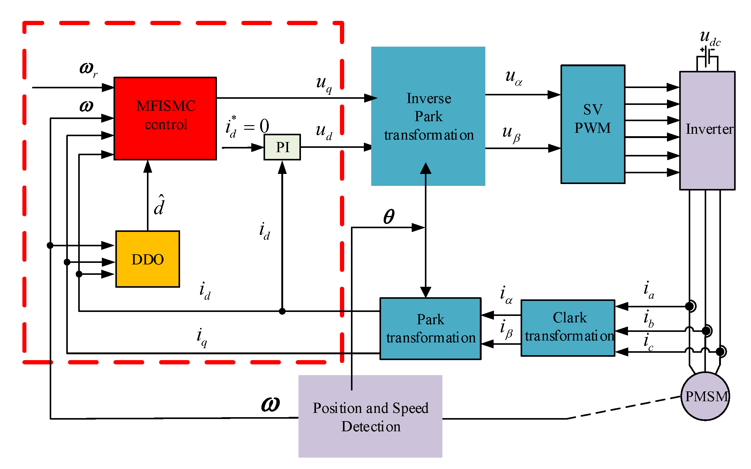
Figure 1. Control block diagram.
Symmetry 13 01680 g001
Figure 2. Experimental platform.
Symmetry 13 01680 g002
Figure 3. The configuration of the experimental PMSM drive system.
Symmetry 13 01680 g003
Figure 4. Experimental waveforms at different speeds: (a) n = 200 RPM; (b) n = 600 RPM; and (c) n = 1000 RPM.
Symmetry 13 01680 g004
Figure 5. Experimental waveforms of different speeds under 1 Nm load disturbance: (a) n = 200 RPM; (b) n = 600 RPM; and (c) n = 1000 RPM.
Symmetry 13 01680 g005
Figure 6. Dq-axis current waveform of MFISMC + DDO method at different speeds: (a) n = 200 RPM; (b) n = 600 RPM; and (c) n = 1000 RPM.
Symmetry 13 01680 g006
Figure 7. Electromagnetic torque waveform of MFISMC+DDO method under 1 Nm load disturbance.
Symmetry 13 01680 g007
Figure 8. Estimated value of d 1 .
Symmetry 13 01680 g008
Figure 9. Experimental curves of different speeds: (a) n = −200 RPM; (b) n = −600 RPM; and (c) n = −1000 RPM.
Symmetry 13 01680 g009aSymmetry 13 01680 g009b
Figure 10. Experimental speed waveforms when the speed changes suddenly: (a) n = + 2 00 RPM to n = 2 00 RPM; (b) n = + 4 00 RPM to n = 4 00 RPM.
Symmetry 13 01680 g010
Table 1. Parameters of PMSM.
DescriptionValueUnit
rated speed1000RPM
rated power1.5KW
moment of inertia0.0027kg·m 2
permanent magnet flux0.32Wb
line resistance1.84 Ω
line inductance6.65mH
number of pole pairs4
Table 2. The detailed performance comparison of three kinds of controllers under different reference speed.
Speed (RPM)Control SchemeSpeed Fluctuation (RPM)Adjustment Time (s)
Load UpLoad DownLoad UpLoad Down
200MFISMC + DDO−15+130.120.21
ISMC + DDO−14+160.150.21
PI−29+ 240.190.25
600MFISMC + DDO−14+130.120.16
ISMC + DDO−15+130.140.19
PI−21+190.250.24
1000MFISMC + DDO−13+140.200.19
ISMC + DDO−15+140.230.21
PI−24+200.280.24
Publisher’s Note: MDPI stays neutral with regard to jurisdictional claims in published maps and institutional affiliations.