
Improved Analytical Method for Interfacial-Slip Control Design of Steel–Concrete Composite Structures


Abstract
:1. Introduction
2. Interfacial Interaction of the Composite Structures
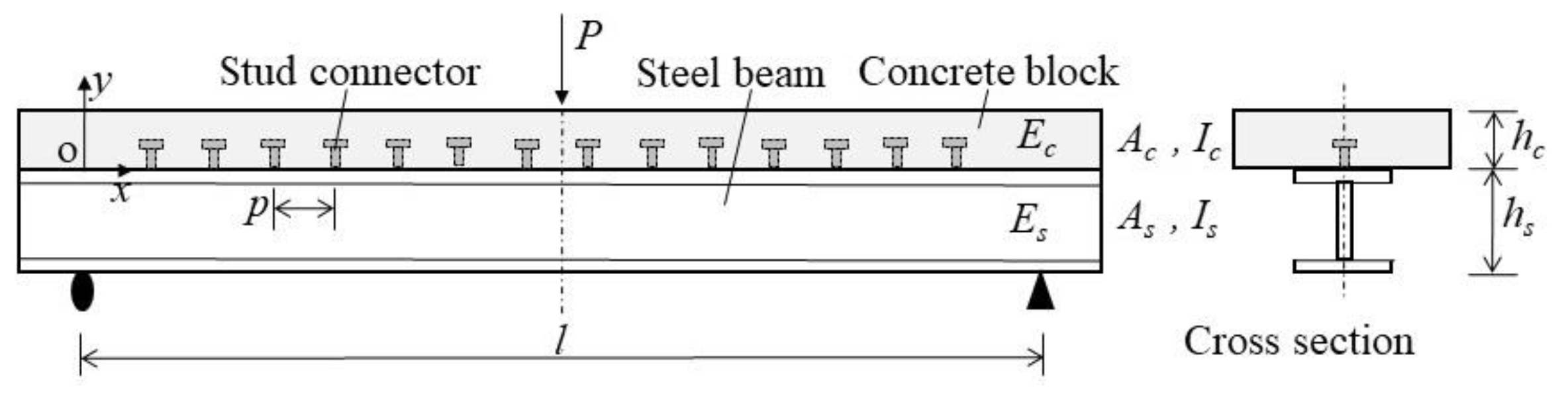
2.1. Model Description and Assumption
- (1)
- The interfacial shear stress is proportional to the slip, which giveswhere is the longitudinal spacing of shear studs (mm); is the interfacial shear stress per unit length (N/mm); is the shear stiffness of shear studs (N/mm); and is interfacial slip between the steel beam and concrete slab (mm).
- (2)
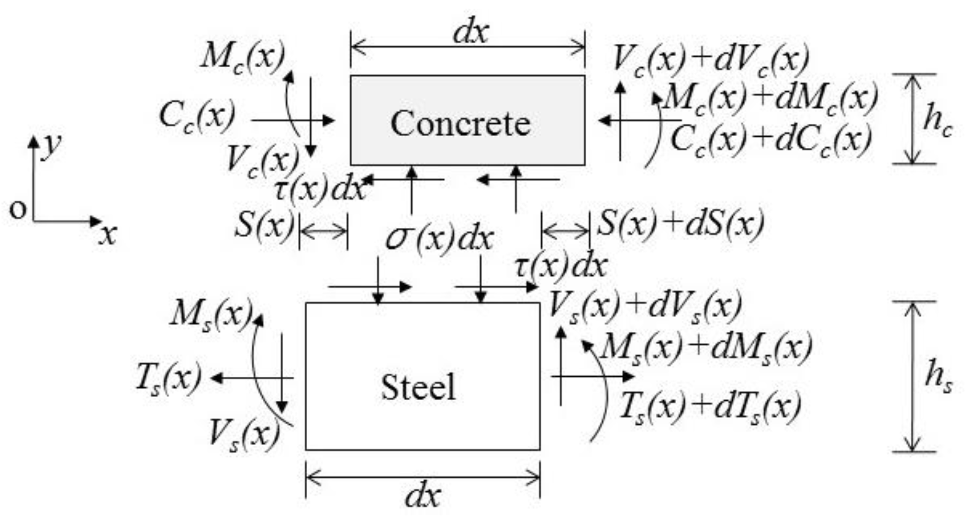
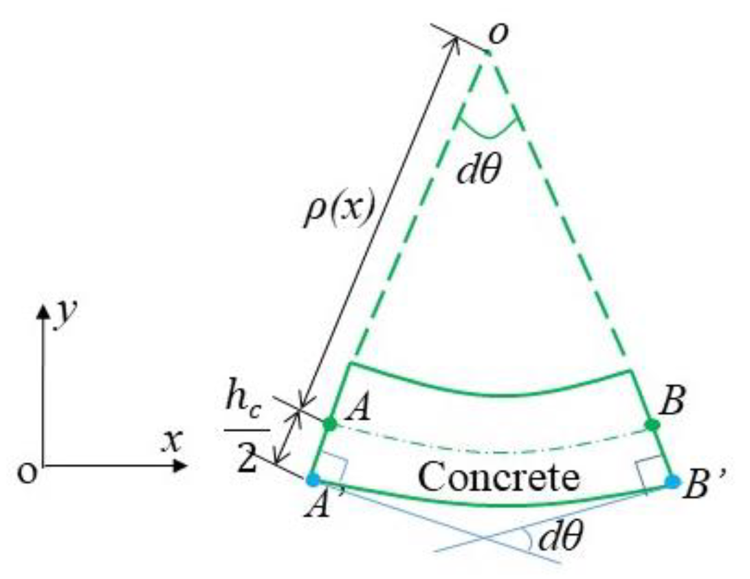
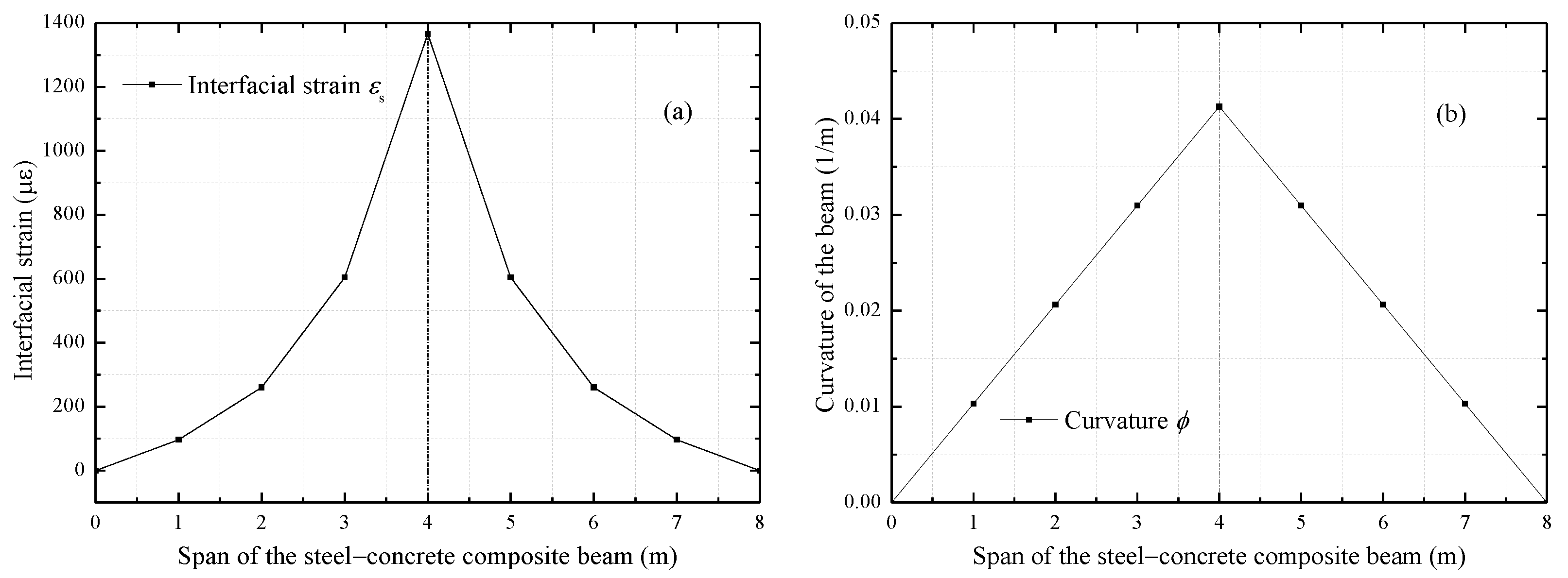
- The steel beam and the concrete slab have the equivalent curvature, and both follow the plane cross-section hypothesis. Thus, the relationship between the curvature and the strain can be established. An infinitesimal element of the composite beam, , is selected to be approximately equivalent to an arc segment. When the micro-arc section has an angle, , (i.e., the tangent angle corresponding to the micro-arc section), as shown in Figure 3, the tensile strain at the bottom of the concrete slab can be obtained from the geometric relationship:
2.2. Theoretical Modeling
2.3. Discussions on the Analytical Solution
3. Analytical Model Validation Based on Testing Results
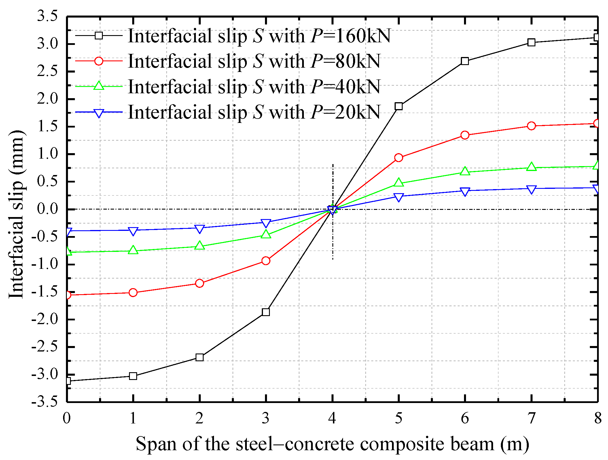
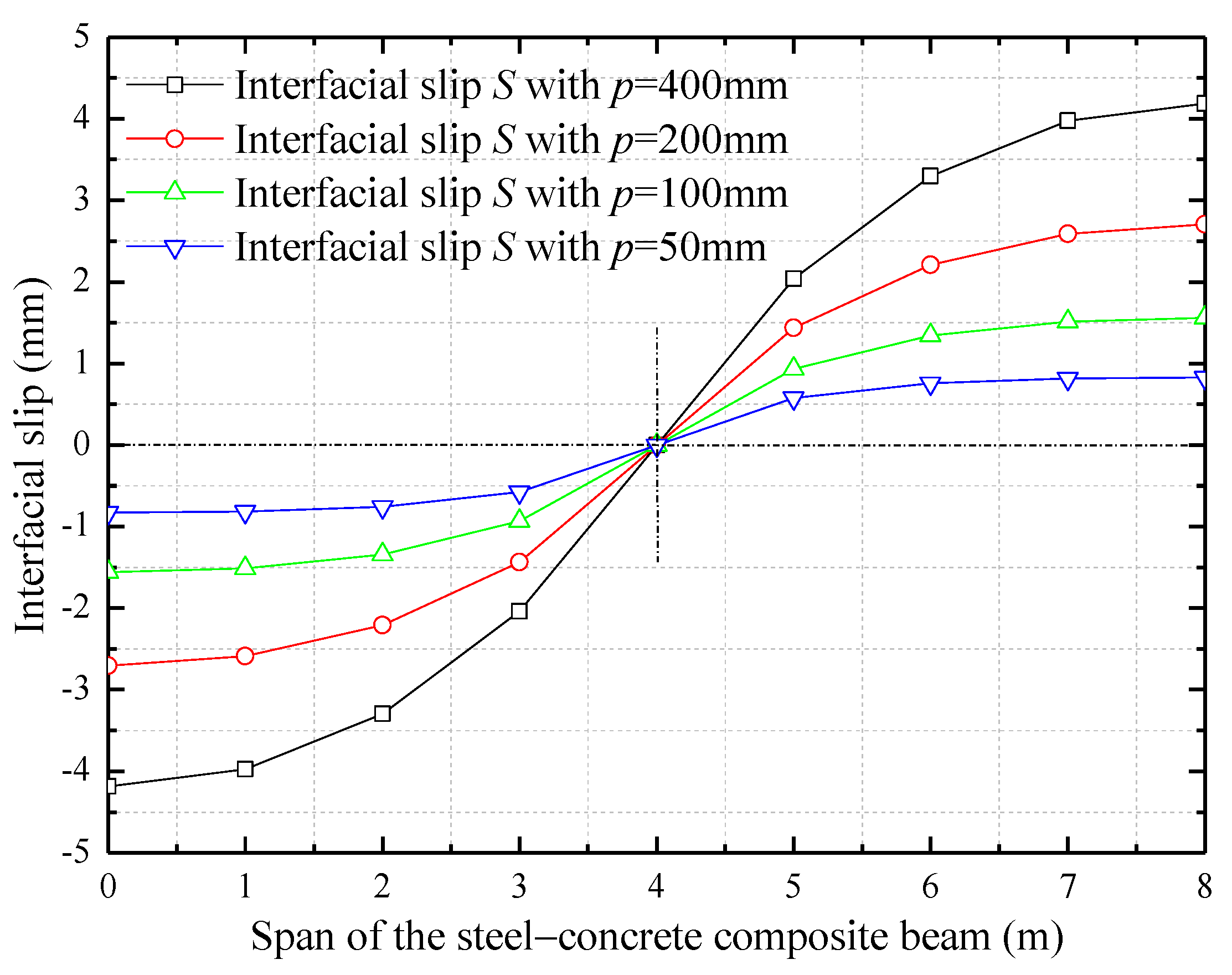
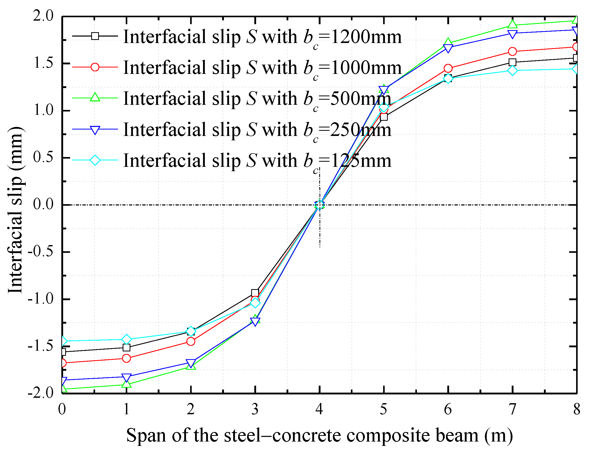
4. Improved Interfacial Design Based on Parametric Analysis
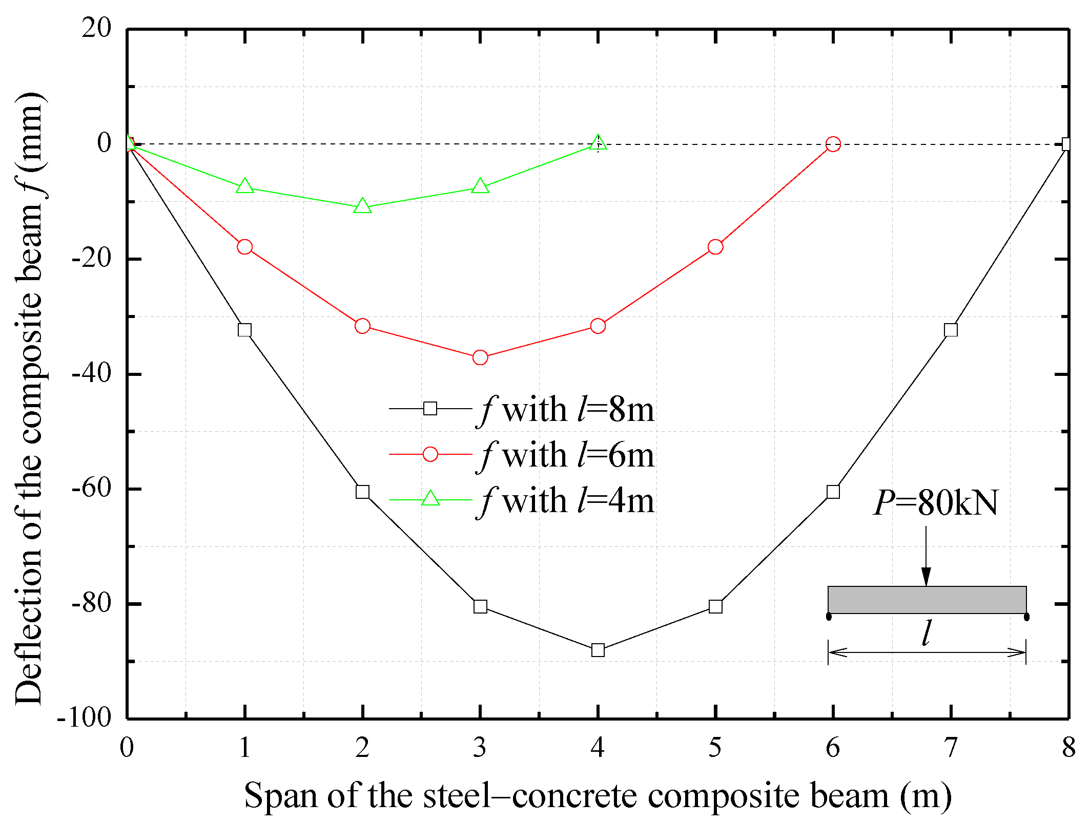
5. Slip-Induced Deformation Properties of Composite Structures
5.1. Deflection of the Composite Beam without the Slip Effect
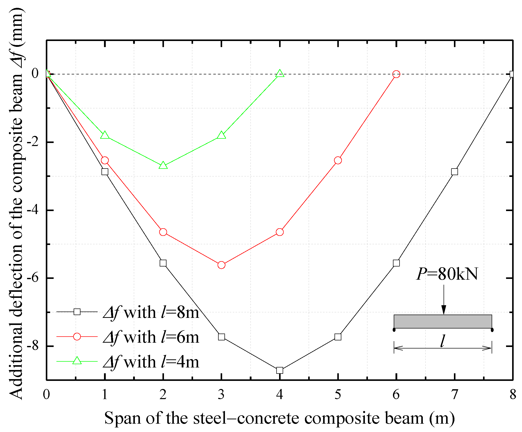
5.2. Slip-Induced Additional Deflection of the Composite Beam
6. Conclusions
- (1)
- The analytical solution of the interfacial slip of the composite beam can be illustrated with Equations (23) and (33), and the interfacial strain can be described by Equations (34a) and (34b). The case of composite beams under uniform loads or other kinds of loads can be solved in a similar way. The study, for the first time, provides the closed-form solution for straightforwardly describing the interfacial interaction.
- (2)
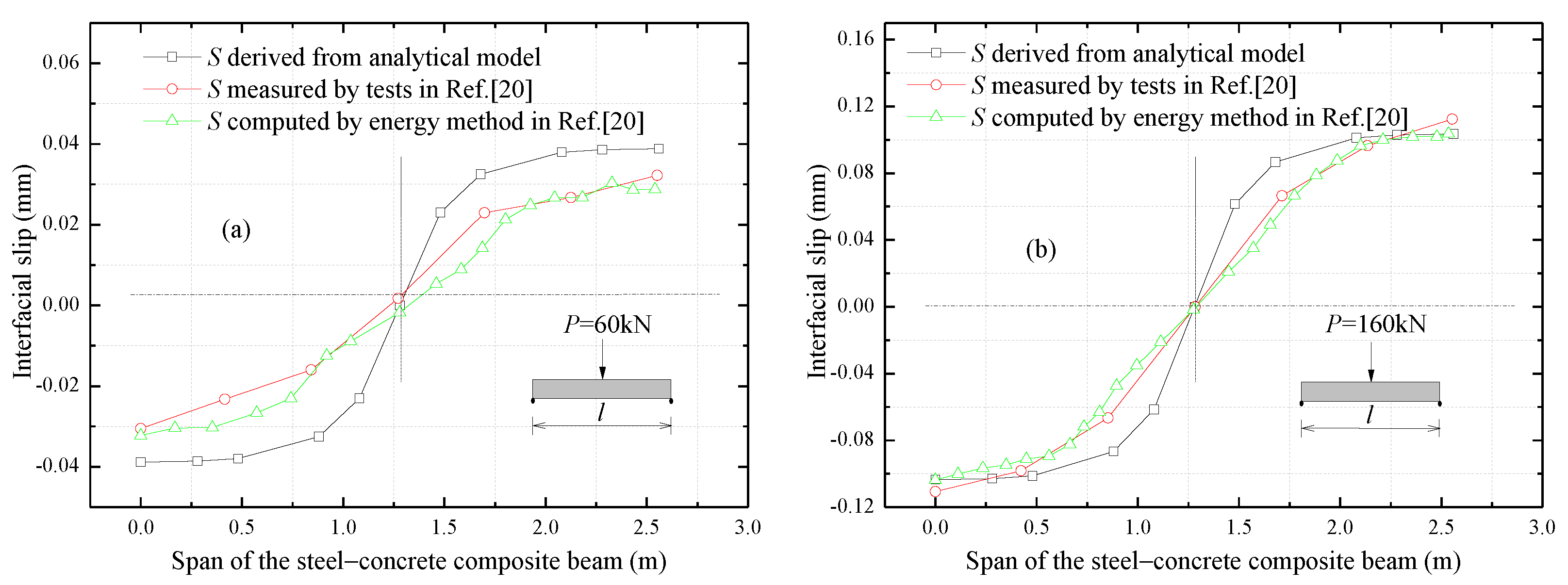
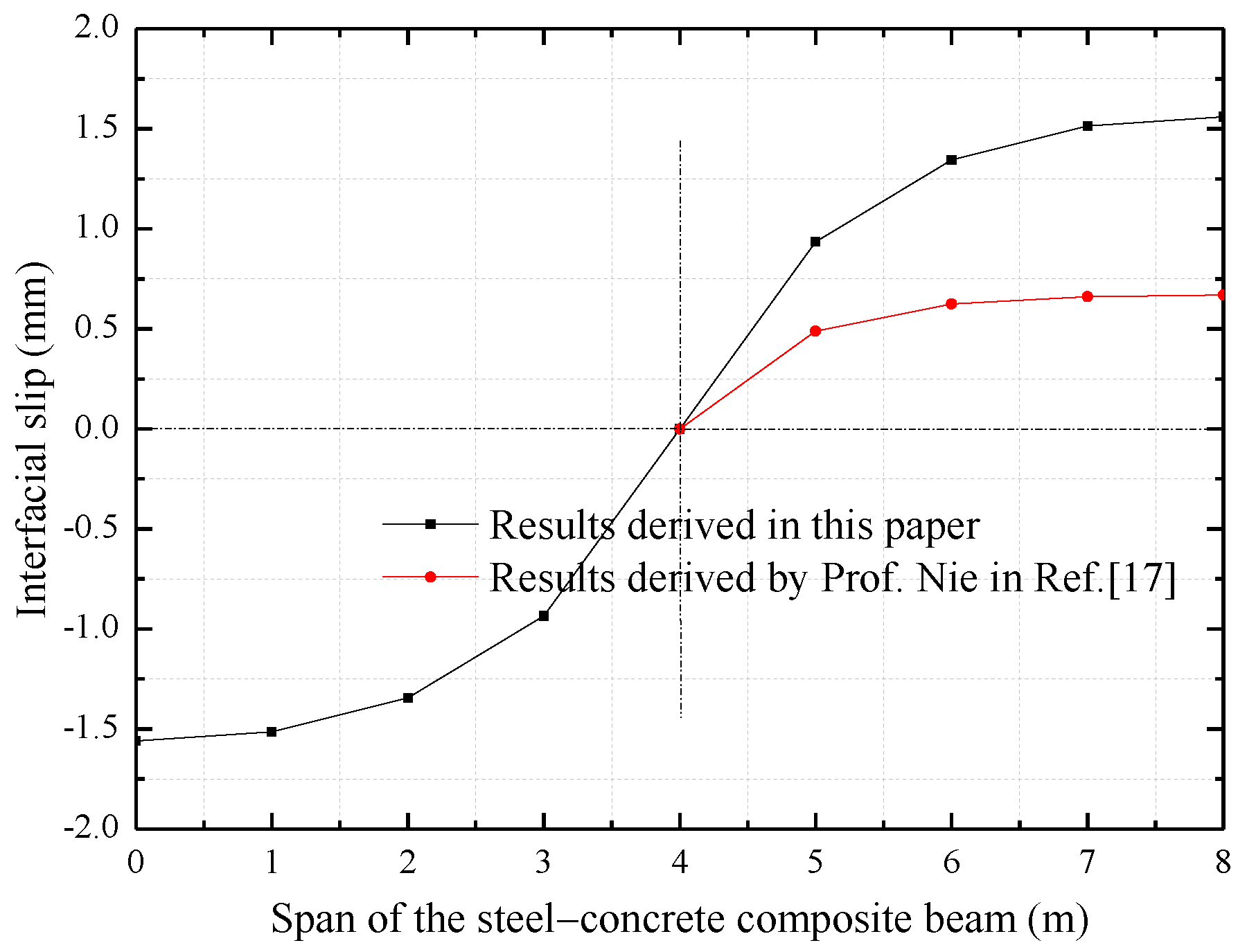
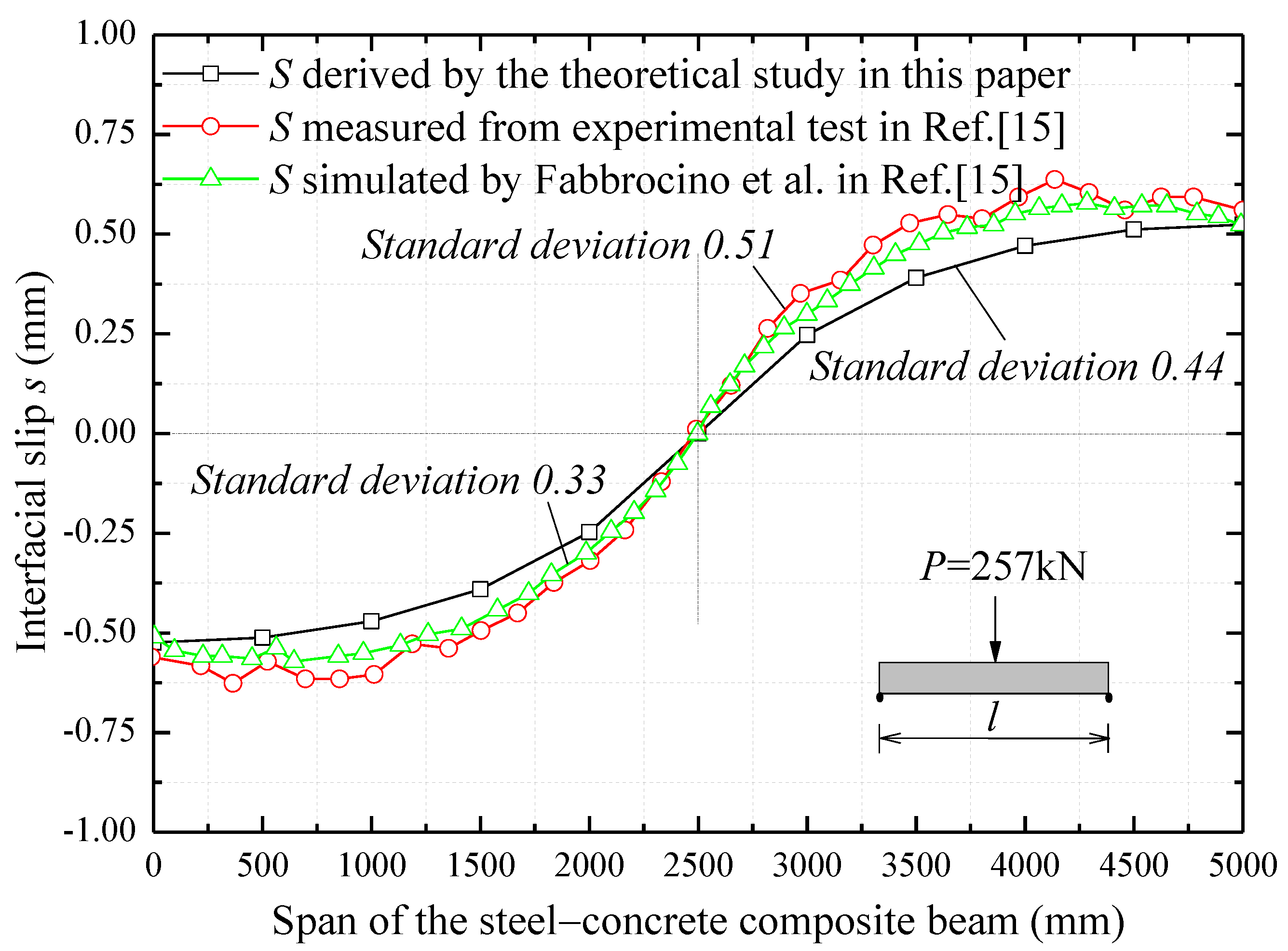
- The comparison analysis with the results of experimental tests, numerical study and energy method performed by Fabbrocino et al. in Ref. [15] and Jiang et al. in Ref. [20], validates the predictions obtained by the proposed analytical model. This means the proposed model can be used for describing the interfacial interaction and structural performance of the composite beam.
- (3)
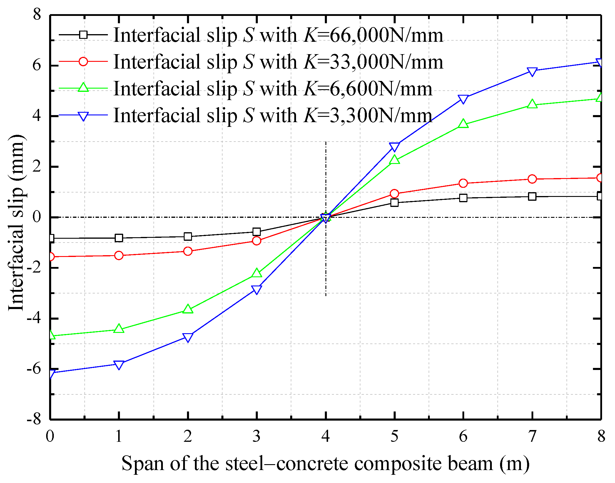
- Priority should be given to the design of interfacial shear stiffness and the longitudinal spacing of shear studs to achieve the optimal interfacial strength of the composite beam. The ultimate load and the width of concrete slab can be considered in turn to obtain the best interfacial connection performance and avoid the occurrence and propagation of interfacial slip.
- (4)
- The interfacial slip effect should be carefully considered for composite beams with relatively short spans (i.e., beams with about 8 m span). In general, the slip-induced deflection should be considered to judge the deformation and bearing capacity of the composite beam, since the slip-induced additional deflection can have a weight in the global deflection that cannot be ignored.
- (5)
- The analytical model describing the interfacial shear stress between the concrete slab and the top flange of the steel beam can be used to develop a constitutive model for the case of a composite beam subjected to bending. The latter model can be used to determine the effect of the interfacial slip on the load-carrying capacity and stiffness of the beam considered.
Author Contributions
Funding
Institutional Review Board Statement
Informed Consent Statement
Data Availability Statement
Acknowledgments
Conflicts of Interest
References
- Metelli, G.; Cairns, J.; Conforti, A.; Plizzari, G.A. Local bond behavior of bundled bars: Experimental investigation. Struct. Concr. 2021, 1–16. [Google Scholar] [CrossRef]
- Zhang, Y.; Wang, M.; Yu, L.; Guo, X.; Liu, K.; Yang, H. Experimental research and mechanical analysis on the bond-slip behavior between concrete and corroded I-shaped steel. Struct. Concr. 2021, 1–15. [Google Scholar] [CrossRef]
- Al-Qaralleh, M.; Toutanji, H.; Eljufout, T. Overloading impact on the flexural behavior of RC beams strengthened with FRP composites under fatigue: Experimental study. Eng. Struct. 2020, 221, 111045. [Google Scholar] [CrossRef]
- Duvnjak, I.; Bartolac, M.; Damjanović, D.; Košćak, J. Performance assessment of a concrete railway bridge by diagnostic load testing. Struct. Concr. 2020, 21, 2363–2376. [Google Scholar] [CrossRef]
- Wang, H.; Dai, J.-G. Strain transfer analysis of fiber Bragg grating sensor assembled composite structures subjected to thermal loading. Compos. Part B Eng. 2019, 162, 303–313. [Google Scholar] [CrossRef]
- Nie, J.; Shen, J.; Yuan, Y. General formula for calculating the deformation of steel-concrete simply supported composite beams. Eng. Mech. 1994, 11, 1–7. [Google Scholar]
- Nie, J.; Shen, J.; Yu, Z. A reduced stiffness method for deformation calculation of steel-concrete composite beams with slip effect. J. Civ. Eng. 1995, 28, 11–17. [Google Scholar]
- Ranzi, G.; Leoni, G.; Zandonini, R. State of the art on the time-dependent behaviour of composite steel–concrete structures. J. Constr. Steel Res. 2013, 80, 252–263. [Google Scholar] [CrossRef]
- Zhang, S.; Xue, W.; Liao, X. Theoretical analysis on long-term deflection of GFRP-concrete hybrid structures with partial interaction. Compos. Struct. 2019, 216, 1–11. [Google Scholar] [CrossRef]
- Newmark, N.M.; Siess, C.P.; Viest, I.M. Tests and analysis of composite beams with incomplete interaction. Proc. Soc. Exp. Stress Anal. 1951, 9, 75–92. [Google Scholar]
- Adekola, A.O. The dependence of shear lag on partial interaction in composite beams. Int. J. Solids Struct. 1974, 10, 389–400. [Google Scholar] [CrossRef]
- Girhammar, U.A.; Pan, D. Dynamic analysis of composite members with interlayer slip. Int. J. Solids Struct. 1993, 30, 797–823. [Google Scholar] [CrossRef]
- Oehlers, D.J.; Sved, G. Composite beams with limited-slip-capacity shear connectors. ASCE J. Struct. Eng. 1995, 121, 932–938. [Google Scholar] [CrossRef]
- Oehlers, D.J.; Nguyen, N.T.; Ahmed, M.; Bradford, M.A. Partial interaction in composite steel and concrete beams with full shear connection. J. Constr. Steel Res. 1997, 41, 235–248. [Google Scholar] [CrossRef]
- Fabbrocino, G.; Manfredi, G.; Cosenza, E. Non-linear analysis of composite beams under positive bending. Comput. Struct. 1999, 70, 77–89. [Google Scholar] [CrossRef]
- Dezi, L.; Gara, F.; Leoni, G.; Tarantino, A.M. Time-dependent analysis of shear-lag effect in composite beams. ASCE J. Eng. Mech. 2001, 127, 71–79. [Google Scholar] [CrossRef]
- Nie, J.; Cai, C.S. Steel-concrete composite beams considering shear slip effects. ASCE J. Struct. Eng. 2003, 129, 495–506. [Google Scholar] [CrossRef] [Green Version]
- Huang, Y.; Nie, J.; Yi, W. Stiffness of steel-concrete composite frame beam with slip effect. Eng. Mech. 2012, 29, 88–92. [Google Scholar] [CrossRef]
- Fan, J.; Nie, J. Effects of slips on load-carrying capacity of composite beams under negative bending. Eng. Mech. 2005, 22, 177–182. [Google Scholar]
- Jiang, L.; Yu, Z.; Li, J. Theoretical analysis of slip and deformation of steel-concrete composite beam under uniformly distributed loads. Eng. Mech. 2003, 20, 133–137. [Google Scholar]
- Zhou, L.; Jiang, L.Z.; Yu, Z.W. Analysis of composite beams of steel and concrete with slip and shear deformation. Eng. Mech. 2005, 20, 133–137. [Google Scholar]
- Ranzi, G.; Bradford, M.A.; Uy, B. A direct stiffness analysis of a composite beam with partial interaction. Int. J. Numer. Methods Eng. 2004, 61, 657–672. [Google Scholar] [CrossRef]
- Gara, F.; Ranzi, G.; Leoni, G. Time analysis of composite beams with partial interaction using available modelling techniques: A comparative study. J. Constr. Steel Res. 2006, 62, 917–930. [Google Scholar] [CrossRef]
- Gara, F.; Ranzi, G.; Leoni, G. Displacement-based formulations for composite beams with longitudinal slip and vertical uplift. Int. J. Numer. Methods Eng. 2006, 65, 1197–1220. [Google Scholar] [CrossRef]
- Ranzi, G.; Gara, F.; Leoni, G.; Bradford, M.A. Analysis of composite beams with partial shear interaction using available modelling techniques: A comparative study. Comput. Struct. 2006, 84, 930–941. [Google Scholar] [CrossRef]
- Ranzi, G.; Bradford, M.A. Analytical solutions for the time-dependent behaviour of composite beams with partial interaction. Int. J. Solids Struct. 2006, 43, 3770–3793. [Google Scholar] [CrossRef] [Green Version]
- Ranzi, G.; Zona, A. A steel–concrete composite beam model with partial interaction including the shear deformability of the steel component. Eng. Struct. 2007, 29, 3026–3041. [Google Scholar] [CrossRef]
- Ranzi, G.; Bradford, M.A. Analysis of composite beams with partial interaction using the direct stiffness approach accounting for time effects. Int. J. Numer. Methods Eng. 2009, 78, 564–586. [Google Scholar] [CrossRef]
- Ranzi, G.; Dall’Asta, A.; Ragni, L.; Zona, A. A geometric nonlinear model for composite beams with partial interaction. Eng. Struct. 2010, 32, 1384–1396. [Google Scholar] [CrossRef]
- Gara, F.; Ranzi, G.; Leoni, G. Short- and long-term analytical solutions for composite beams with partial interaction and shear-lag effects. Int. J. Steel Struct. 2010, 10, 359–372. [Google Scholar] [CrossRef]
- Faella, C.; Martinelli, E.; Nigro, E. Steel–concrete composite beams in partial interaction Closed-form “exact” expression of the stiffness matrix and the vector of equivalent nodal forces. Eng. Struct. 2010, 32, 2744–2754. [Google Scholar] [CrossRef]
- Nguyen, Q.; Hjiaj, M.; Uy, B. Time-dependent analysis of composite beams with continuous shear connection based on a space-exact stiffness matrix. Eng. Struct. 2010, 32, 2902–2911. [Google Scholar] [CrossRef]
- Nguyen, Q.; Hjiaj, M. Nonlinear time-dependent behavior of composite steel-concrete beams. ASCE J. Struct. Eng. 2016, 142, 04015175-1-11. [Google Scholar] [CrossRef]
- Miao, L.; Chen, D. Closed-form solution of composite beam considering interfacial slip effects. J. Tongji Univ. Nat. Sci. 2011, 39, 1113–1119. [Google Scholar]
- Zanuy, C. Analytical equations for interfacial stresses of composite beams due to shrinkage. Int. J. Steel Struct. 2015, 15, 999–1010. [Google Scholar] [CrossRef]
- Uddin, A. A Nonlinear Finite Element Model for Steel-Concrete Composite Beam Using a Higher-Order Beam Theory. Ph.D. Thesis, The University of Adelaide, Adelaide, Australia, 2016. [Google Scholar]
- Uddin, A.; Sheikh, A.H.; Brown, D.; Bennett, T.; Uy, B. A higher order model for inelastic response of composite beams with interfacial slip using a dissipation based arc-length method. Eng. Struct. 2017, 139, 120–134. [Google Scholar] [CrossRef]
- Bertagnoli, G.; Gino, D.; Martinelli, E. A simplified method for predicting early-age stresses in slabs of steel-concrete composite beams in partial interaction. Eng. Struct. 2017, 140, 286–297. [Google Scholar] [CrossRef]
- Shamass, R.; Cashell, K.A. Analysis of stainless steel-concrete composite beams. J. Constr. Steel Res. 2019, 152, 132–142. [Google Scholar] [CrossRef]
- Huang, D.; Wei, J.; Liu, X.; Du, Y.; Zhang, S. Experimental study on influence of post-pouring joint on long-term performance of steel-concrete composite beam. Eng. Struct. 2019, 186, 121–130. [Google Scholar] [CrossRef]
- Wang, H.P.; Ni, Y.Q.; Dai, J.G.; Yuan, M.D. Interfacial debonding detection of strengthened steel structures by using smart CFRP-FBG composites. Smart Mater. Struct. 2019, 28, 115001. [Google Scholar] [CrossRef]


| Content | Label | Value | Unit |
|---|---|---|---|
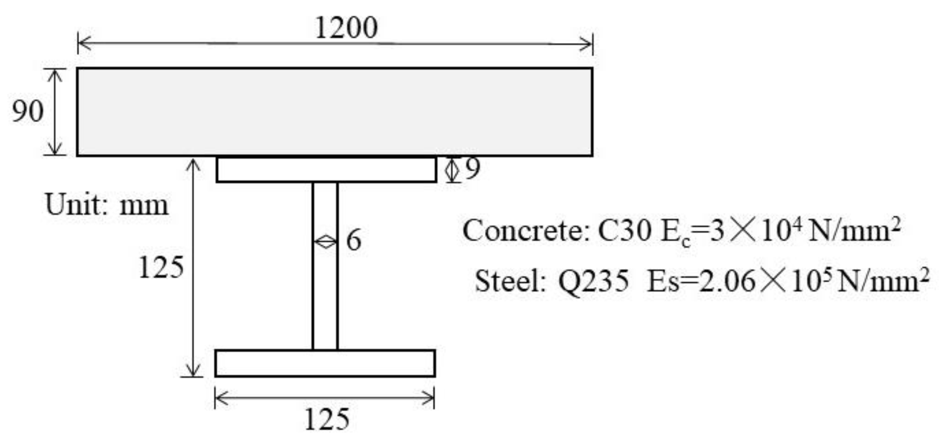
| Elastic modulus of concrete slab | Ec | 30,000 | N/mm2 |
| Elastic modulus of steel beam | Es | 206,000 | N/mm2 |
| Height of concrete slab | hc | 90 | mm |
| Height of steel beam | hs | 125 | mm |
| Height of the composite beam | h | 215 | mm |
| Width of concrete slab | bc | 1200 | mm |
| Width of steel beam | bs | 125 | mm |
| Cross-section area of concrete slab | Ac | 108,000 | mm2 |
| Cross-section area of steel beam | As | 2892 | mm2 |
| Inertial moment of concrete slab | Ic | 72,900,000 | mm4 |
| Inertial moment of steel beam | Is | 8,196,709 | mm2 |
| Longitudinal spacing of shear studs | p | 100 | mm |
| Shear stiffness of shear studs | K | 33,000 | N/mm |
| Span of the composite beam | l | 8 | m |
| Central point load applied on the beam | p | 80 | kN |
| Span l (m) | 8 | 6 | 4 | |
|---|---|---|---|---|
| Deflection (mm) | ||||
| Slip-induced additional deflection at midspan Δf | 8.71 | 5.61 | 2.70 | |
| Deflection at midspan of the composite beam without slip effect f | 88.06 | 37.15 | 11.01 | |
| Deflection at midspan of the composite beam with slip effect f + Δf | 96.77 | 42.76 | 13.71 | |
| Δf/f (%) | 10 | 15 | 24 | |
Publisher’s Note: MDPI stays neutral with regard to jurisdictional claims in published maps and institutional affiliations. |
© 2021 by the authors. Licensee MDPI, Basel, Switzerland. This article is an open access article distributed under the terms and conditions of the Creative Commons Attribution (CC BY) license (https://creativecommons.org/licenses/by/4.0/).
Share and Cite
Wang, H.-P.; Song, T.; Yan, J.-W.; Xiang, P.; Feng, S.-Y.; Hui, D. Improved Analytical Method for Interfacial-Slip Control Design of Steel–Concrete Composite Structures. Symmetry 2021, 13, 1225. https://doi.org/10.3390/sym13071225
Wang H-P, Song T, Yan J-W, Xiang P, Feng S-Y, Hui D. Improved Analytical Method for Interfacial-Slip Control Design of Steel–Concrete Composite Structures. Symmetry. 2021; 13(7):1225. https://doi.org/10.3390/sym13071225
Chicago/Turabian StyleWang, Hua-Ping, Tao Song, Jian-Wei Yan, Ping Xiang, Si-Yuan Feng, and David Hui. 2021. "Improved Analytical Method for Interfacial-Slip Control Design of Steel–Concrete Composite Structures" Symmetry 13, no. 7: 1225. https://doi.org/10.3390/sym13071225
APA StyleWang, H.-P., Song, T., Yan, J.-W., Xiang, P., Feng, S.-Y., & Hui, D. (2021). Improved Analytical Method for Interfacial-Slip Control Design of Steel–Concrete Composite Structures. Symmetry, 13(7), 1225. https://doi.org/10.3390/sym13071225