Article

Comprehensive View of Topological Optimization Scooter Frame Design and Manufacturing

1
Department of Machining, Assembly and Engineering Metrology, Faculty of Mechanical Engineering, VSB-Technical University of Ostrava, 70833 Ostrava, Czech Republic
2
Department of Engineering Materials and Biomaterials, Faculty of Mechanical Engineering, Silesian University of Technology, Konarskiego 18a, 44-100 Gliwice, Poland
3
V-NASS, a.s., Halasova 2938/1a, 70300 Ostrava, Czech Republic
*
Author to whom correspondence should be addressed.
Symmetry 2021, 13(7), 1201; https://doi.org/10.3390/sym13071201
Submission received: 14 June 2021 / Revised: 28 June 2021 / Accepted: 1 July 2021 / Published: 3 July 2021
(This article belongs to the Section Computer)

Abstract

:
The combination of topology optimization (TO) and 3D printing has revolutionized the way components are designed and fabricated. In view of this, this manuscript presents a TO workflow considering the frame of a scooter. In particular, TO is employed to redesign the scooter frame based on a commercial one. The topologically optimized frame is then fabricated with stainless steel 316L utilizing the selective laser melting (SLM) method. In particular, technical obstacles encountered during the process and according solutions are recorded. Given the herein notes, readers who are working with the two technologies can anticipate the technical problems and deliver more effective solutions should any of them arise.

1. Introduction

Additive manufacturing (AM) is well known for its ability to fabricate components in a layer-by-layer manner, without any of the restrictions encountered with conventional manufacturing tools [1,2]. Utilizing an AM method such as selective laser melting (SLM), one can 3D print metallic components which are complex [3,4], functional [5,6], lightweight, and with even higher mechanical properties in comparison with their wrought counterparts [7]. Indeed, thanks to the listed advantages, SLM has attracted the attention of the researchers not only from academy but also from industry, and SLM-produced components have found their place in various fields such as the automotive [8,9,10], aerospace [11,12,13,14,15], and medical [16,17] industries.
From the design perspective, the topology optimization (TO) technique is closely associated with AM [18,19,20,21,22,23]. To obtain an optimal structural design, three prominent methods, namely topology, shape, and sizing optimizations, have been employed. As a matter of fact, TO stands out from the other two thanks to the broadest design area it offers, without the need to consider the initial structural configurations [24]. Additionally, sizing and shape optimization are utilized to polish the TO results, which has become a practice for drafting structural optimal designs. To implement TO, designers during the conceptualizing stage have to prespecify certain constraints for their components such as the crucial geometrical features, component weights, load cases, and material properties [25]. Subsequently, a design area is constructed as per the determined criteria, within which the materials are spatially filled in to form the desired components. In other words, the TO software distributes the materials where they are needed the most to avoid excess material usage. However, due to the fact that TO is extremely sensitive to the load case setting, one can instantly spot the inaccuracies of a TO result at first glance, because two different load cases on a component would yield two different TO results within the same design area. Therefore, the output of TO should serve solely as a potential draft, and delivering the final functional design should primarily rely on the modeling skills of the designers.
Keeping in mind the pros and cons of the TO technique, one can sufficiently cut weight and reduce the number of needed components on their designed parts [26,27,28]. Additionally, owing to the mechanism of the TO technique, its output inherits bionic shapes which can be utilized for not only functional, but also customized and aesthetically pleasing designs [29,30,31,32]. It can be witnessed today that designers adopt complex lattice structures into topologically optimized designs for further weight cutting and (perhaps) better performance [33]. Moreover, thanks to the gap bridging AM, these designs, which cannot be produced by the traditional manufacturing methods, can be fabricated with neglectable deviation in comparison with their CAD counterparts [8,34,35].
Recent years have witnessed the private sector invest heavily in TO and AM regarding optimizing the car chassis [36], car components [37], bike chassis [38,39], aircraft wing [40], and even rocket [41]. In addition to the aesthetic and customizable aspects, one main factor to be considered is the weight saving due to the fact that, in the long run, it significantly reduces the fuel consumption per kilogram and, thus, the operation cost. Additionally, due to the fact the AM is still in its early stage, there is a lack of published data about costing and standards for TO and AM components. There is also a dependence on machine, labor, and material costs for this technology. Hence, it is worth noting that the evaluation of applicability and cost analysis for conventional production may not be applicable for AM technology.
With inspiration taken from the above studies, this manuscript suggests a workflow of the TO process considering a scooter frame from the design to the manufacturing stage. Specifically, a conventional scooter frame was examined, TO was utilized subsequently for the redesigning purpose, and SLM AM technology was deployed to fabricate the frame with stainless steel 316L. The frame eventually underwent geometric and strength inspections for comparison with its CAD and conventional counterparts. The TO scooter frame was produced following the workflow presented in Figure 1.
This manuscript is structured according to the framework in Figure 1 for better comprehensibility. Consequently, the contributions of this manuscript can be listed as follows:
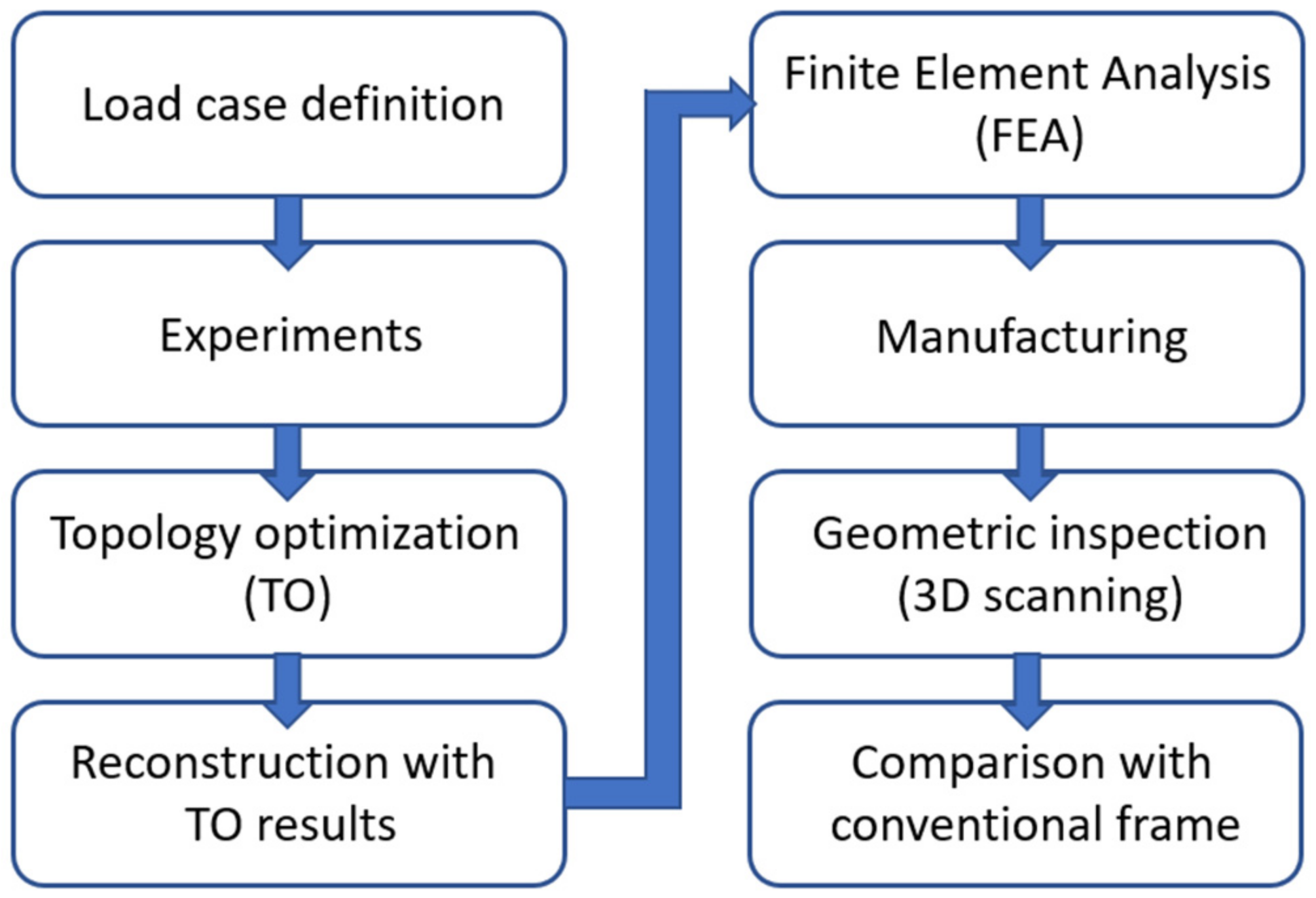
  • Presenting a typical framework for fabricating topologically optimized products;
  • Reporting arising technical issues and practical solutions at each stage of the process;
  • Showcasing how TO and AM can be combined to deliver a futuristic and functional product, as well as the pros and cons in comparison with conventional manufacturing methods;
  • Suggesting possible improvements that can be introduced for better fabricating TO components with AM utilizing existing numerical and manufacturing tools.
Following the introduction, Section 2 presents the materials and methods used for elaboration of the proposed framework. Consequently, Section 3 summarizes the findings and possible future works to improve the quality of topologically optimized components.

2. Materials and Methods

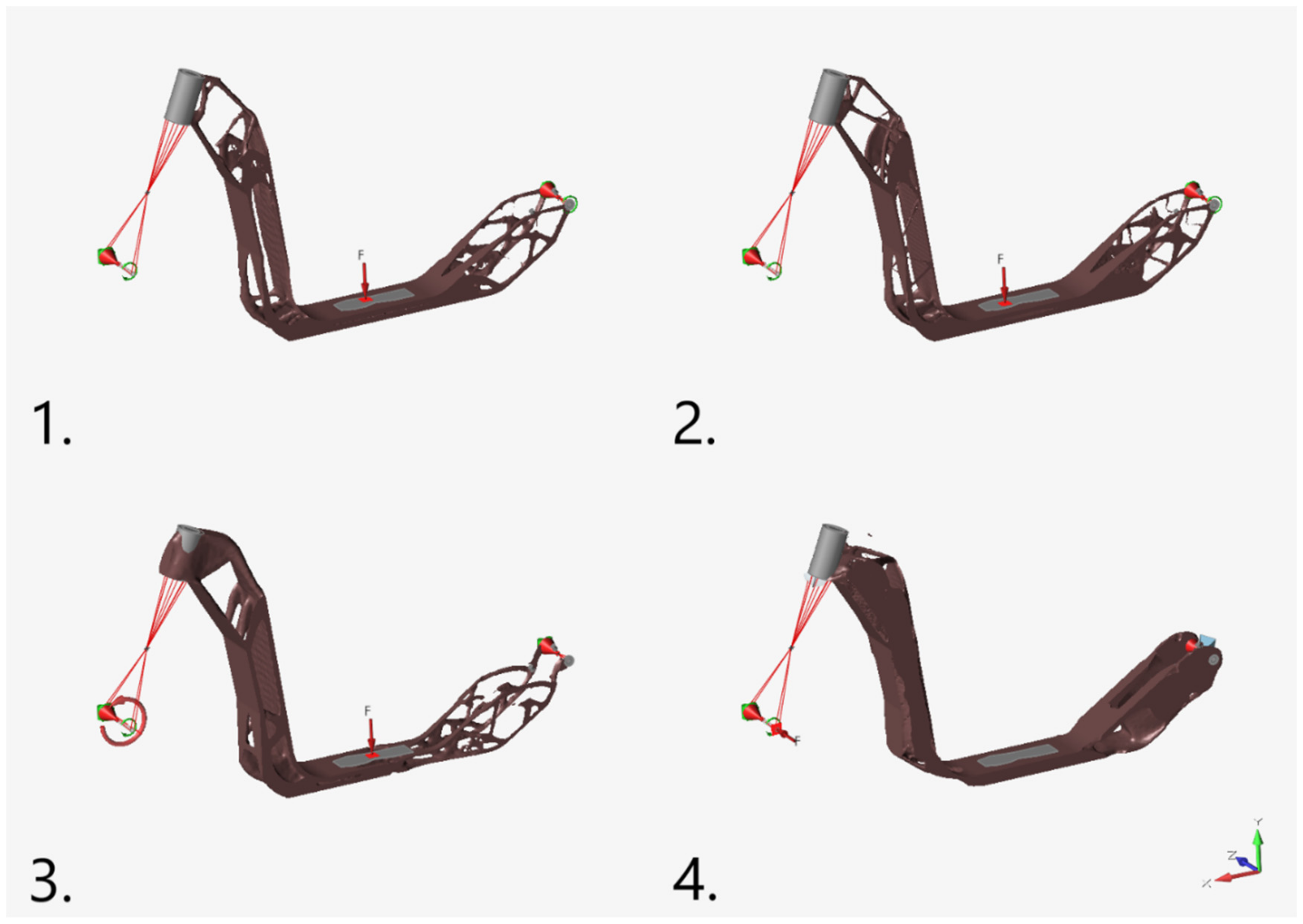
2.1. Load Case Definition and Experiments

As mentioned in Section 1, for TO studies, it is necessary to define the typical load cases for the conventional scooter under operation. In this study, there are four load scenarios considered and, accordingly, the experimental results on the conventional frame are presented.

2.1.1. Normal Operation

When the scooter is under normal operation, i.e., driving on a flat surface, the mass of the 80 kg rider will exert a force of 80 kg × 1g = 785 N on the step board, causing bending in the middle of the frame with a deflection of 11 mm. The clearance between the ground and the frame was determined to be a minimum of 60 mm, which was considered for the redesigned frame to ensure the functionality and comfortability of kicking while driving.

2.1.2. Drop

When a 80 kg rider lands on the ground from a height of up to 1 m after performing a jump or riding off a jump ramp, road bump, or kerb, the free fall exerts an impact force which is transferred from the two wheels to the whole scooter frame. The dynamic factor was chosen to be 3g, leading to an impact force of 80 kg × 3g = 2354 N on the step board of the scooter.

2.1.3. Braking

When braking, the rider’s mass will be shifted forward, thereby exerting the braking force the most severely on the front fork neck. A deceleration value of 5 m·s−2 was chosen for this load case with the force applied on the handles when braking was equal to 80 kg × 5 m·s−2 = 400 N. The scooter was also loaded with 80 kg of the rider’s mass.

2.1.4. Torsional Stiffness

When cornering, the whole frame experiences a twist about the two wheels. To assess the torsional stiffness of the conventional scooter frame, it was rotated 90° from its standing position, and the back wheel was fixed on a testing deck. The steering column was rotated facing the ground to simulate the 90° steering. A mass of 100 N was applied on the front wheel, and the deflection of the fork neck was measured to be 30 mm.
According to the above load cases, critical areas to be considered for the TO study were estimated and are circled in Figure 2.
The scooter dimensions had a maximum of 1720 mm length and 960 mm height. The circled areas, from left to right, are the transition between the head tube and the down tube, the transition between the down tube and the step board, and the transition between the step board and the rear fork, which are hereafter orderly referred to as fork neck, front transition, and rear transition. Having considered these assumptions and experimental results, the design area of the scooter frame for TO was modeled as described in the next section.

2.2. Topology Optimization (TO)
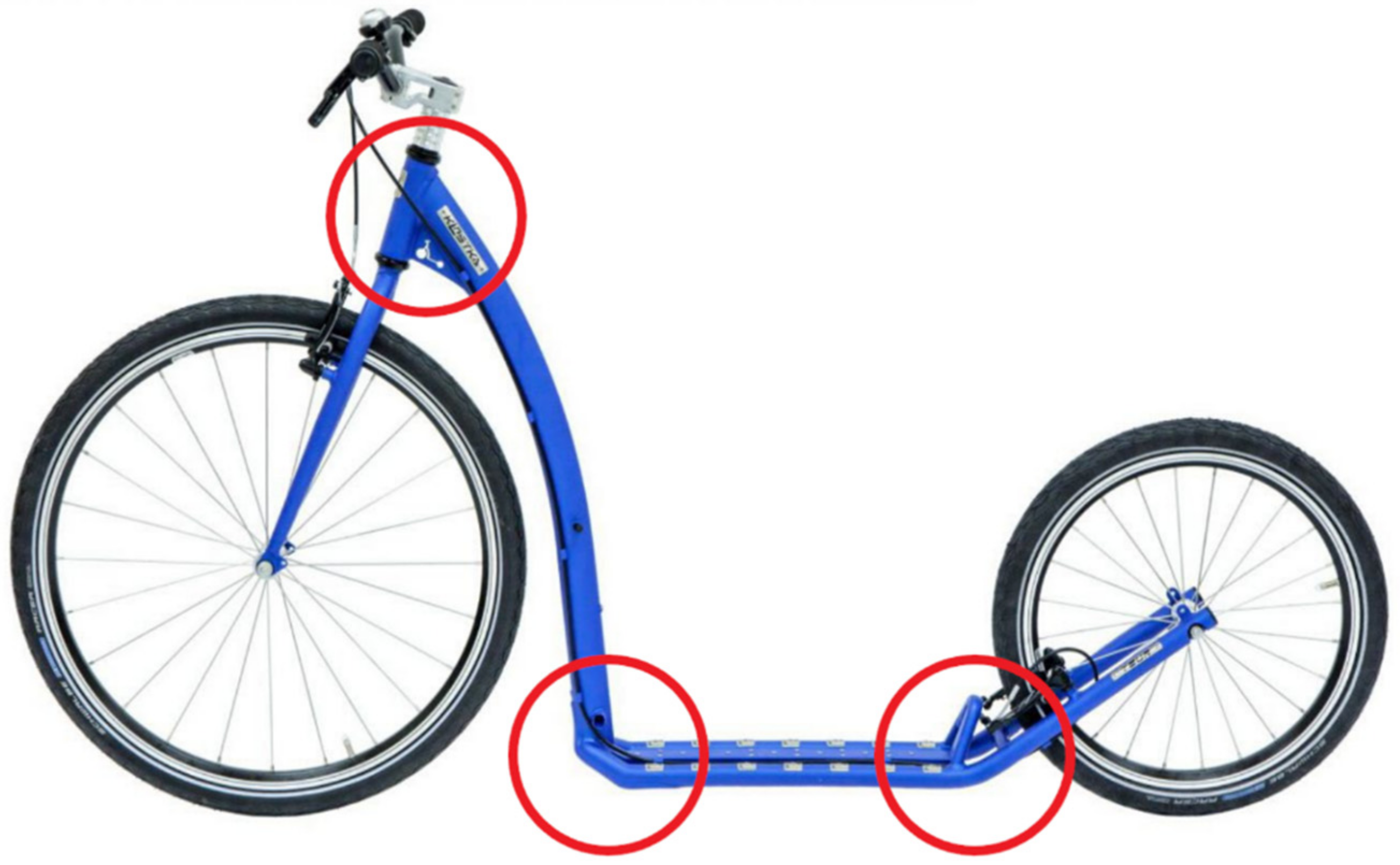
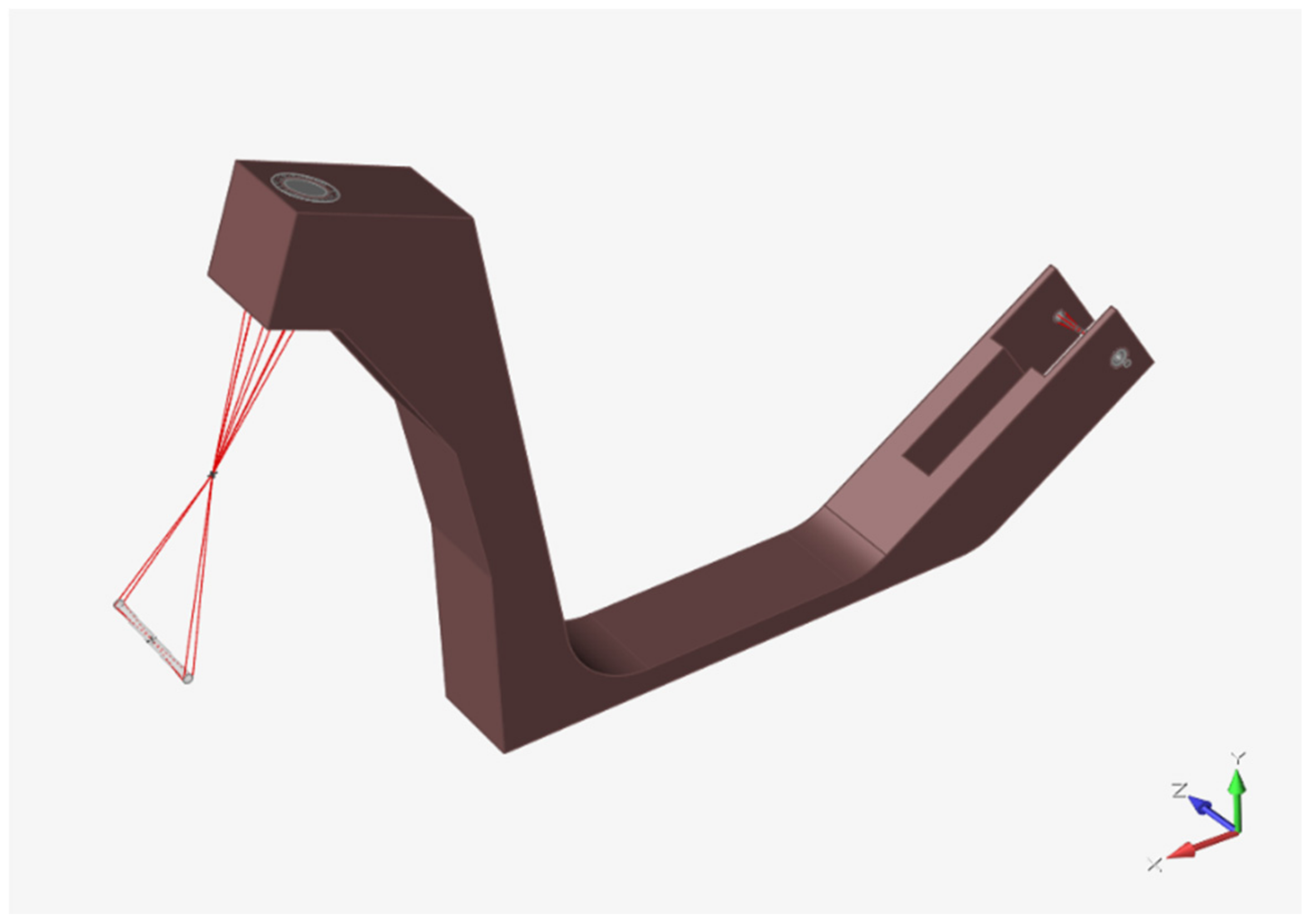
2.2.1. Design Space

The design space must be continuous and as voluminous as possible in order to package the whole structure under TO study. To ensure the freedom of TO, it is recommended not to take effort modeling a detailed design space. Subsequently, after finishing the design space, it is necessary to define the non-design spaces, which cannot be modified during the TO process. These can be functional features, connection points, etc. Accordingly, it is possible to observe the utilized design space for this study in Figure 3, Along with notes and explanations on the modeled features.
As illustrated in Figure 3, the grey-colored features are the non-design spaces, i.e., for assembling the steering column in front and for bearings in the back. The design space had dimensions of up to 1100 mm long and 727 mm high. Additionally, there were two bars representing the axes of the front and back wheels, connected to the non-design spaces such that loads could be applied to and transferred from the wheels to the frame structure according to the previously defined load cases. Remarkably, the three predicted critical areas were modeled with a thicker section so that more material could be distributed there for weak spot reinforcement. Last but not least, symmetric conditions were set for the TO study.
Having finished the design space, it was necessary to assign the material properties of the 3D printed 316L to the model, as detailed below.

2.2.2. Materials and TO Objectives
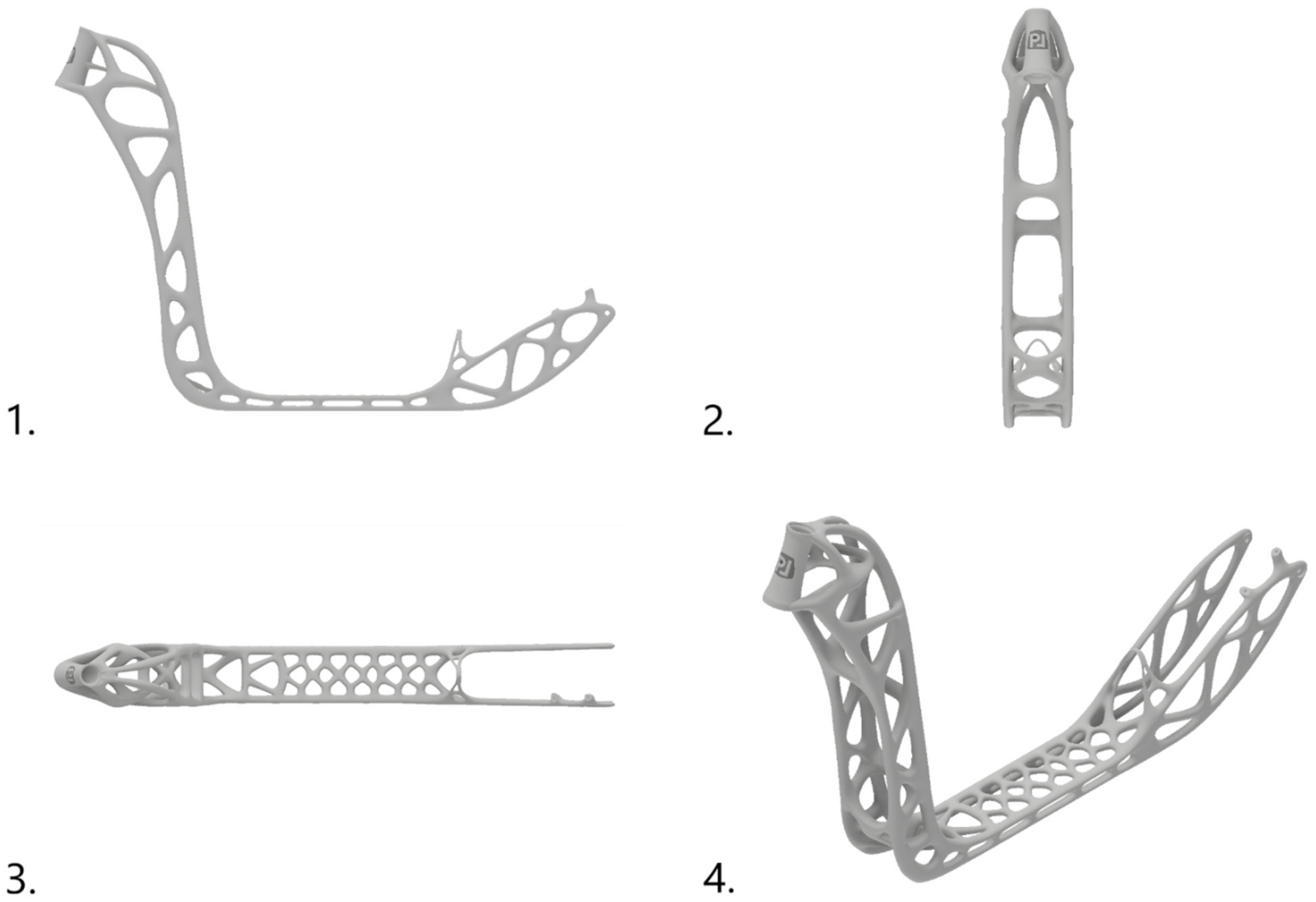
The authors of [42] studied how different printing parameter sets affect the mechanical properties of 3D printed stainless steel 316L, and the optimized set was utilized for manufacturing the frame in this manuscript. Accordingly, the best material properties that can be obtained are presented in Table 1.
Material description is important for TO because of the objective setting in the TO software. For this TO study, the software SolidThinking Inspire was deployed, and the objective of the TO was to obtain the maximum stiffness with 30% of the volume of the design space being filled, and the minimum thickness of the trusses constructing the frame was set to 10 mm.

2.2.3. TO Results

Figure 4 illustrates the TO results under the four aforementioned load cases and the set objectives.
One can observe the similarities between the TO result of the frame under normal operation, (1) in Figure 4, and that being dropped from the height of 1 m, (2) in Figure 4. In the drop case, the frame is subjected to more severe load as the 80 kg mass of the driver is multiplied by 4g, leading to the fork neck and the front and rear transitions being reinforced with thicker material sections and more trusses. In the braking situation, (3) in Figure 4, material was subtracted from the rear of the frame and more was added to the front of the frame, including the fork neck and the front transition. Except for the case of torsional stiffness, (4) in Figure 4, material cutting can be witnessed in the middle of the step board. Eventually, for the TO result under a 100 N torsional stiffness test, the front transition did not contribute to the stiffness of the frame since a substantial amount of material was subtracted from there. The TO results agree well with the aforementioned critical area prediction.

2.3. Summary of TO Results for Redesign

2.3.1. Solid Model

The TO results were summarized utilizing the PolyNURBS function in SolidThinking Inspire software. According to [43], this technique helps in tracing the tessellated surfaces of the Stereolithography (STL) files to transform them into smooth, CAD-compatible NURBS models. These models can subsequently be exported to other formats for designing and manufacturing purposes. Specifically, the traced geometry, so-called PolyNURBS, is based on the TO space, whose dimensions can be modified during the tracing process according to the needs of the designers. Thanks to this, the final design of the scooter frame was established, as shown in Figure 5.
As can be observed in Figure 5, the conversion took into account the symmetric nature of the scooter frame. With respect to the TO results, attention was paid to the fork neck, the front and rear transitions, and the rear fork, as more material was distributed there. One of the key features for maximal stiffness was the braided design of the fork neck. Moreover, the logo of the laboratory was added. Instead of the solely carved-in feature suggested in the TO results, the step board was reinforced with vertical trusses for stiffening. At the rear transition, a V-shaped feature was additionally designed mimicking the conventional frame for safety purposes, preventing the driver’s legs from colliding with the back wheel. Subsequently, the model could be processed further for the manufacturing stage.

2.3.2. Sectioned and Hollowed Model

There was a need to divide the frame into eight different sections in order to fit it in the limited space of the building chamber of the Renishaw AM400 printer. This size is by default L250 × W250 × H300, which must be then subtracted from the no-build zone due to four corner screws for mounting the building platform to the printer, leaving the available space for printing of L248 × W248 × H285. Furthermore, the default thickness of the building platform is 15 mm for H300, leaving only H285, and adjustments must be made accordingly for different platform thicknesses. The sectioned frame can be seen in Figure 6.
The PolyNURBS results were solid, which would result in an overweighted scooter frame. Thus, the frame was hollowed with an outer thickness of 1.2 mm utilizing the software Materialise Magics. In Figure 7, two hollowed sections of the frame are presented. Furthermore, the transitions between them were designed with a special fitting for frame assembly by welding.
This fitting feature was applied to every other section of the frame. There was a clearance of 0.2 mm in the fitting, allowing the penetration of the filler material during welding. Details about welding operation are discussed further in the upcoming section.
After finalizing the CAD design, finite element analysis (FEA) was conducted to pre-assess the stiffness of the frame.

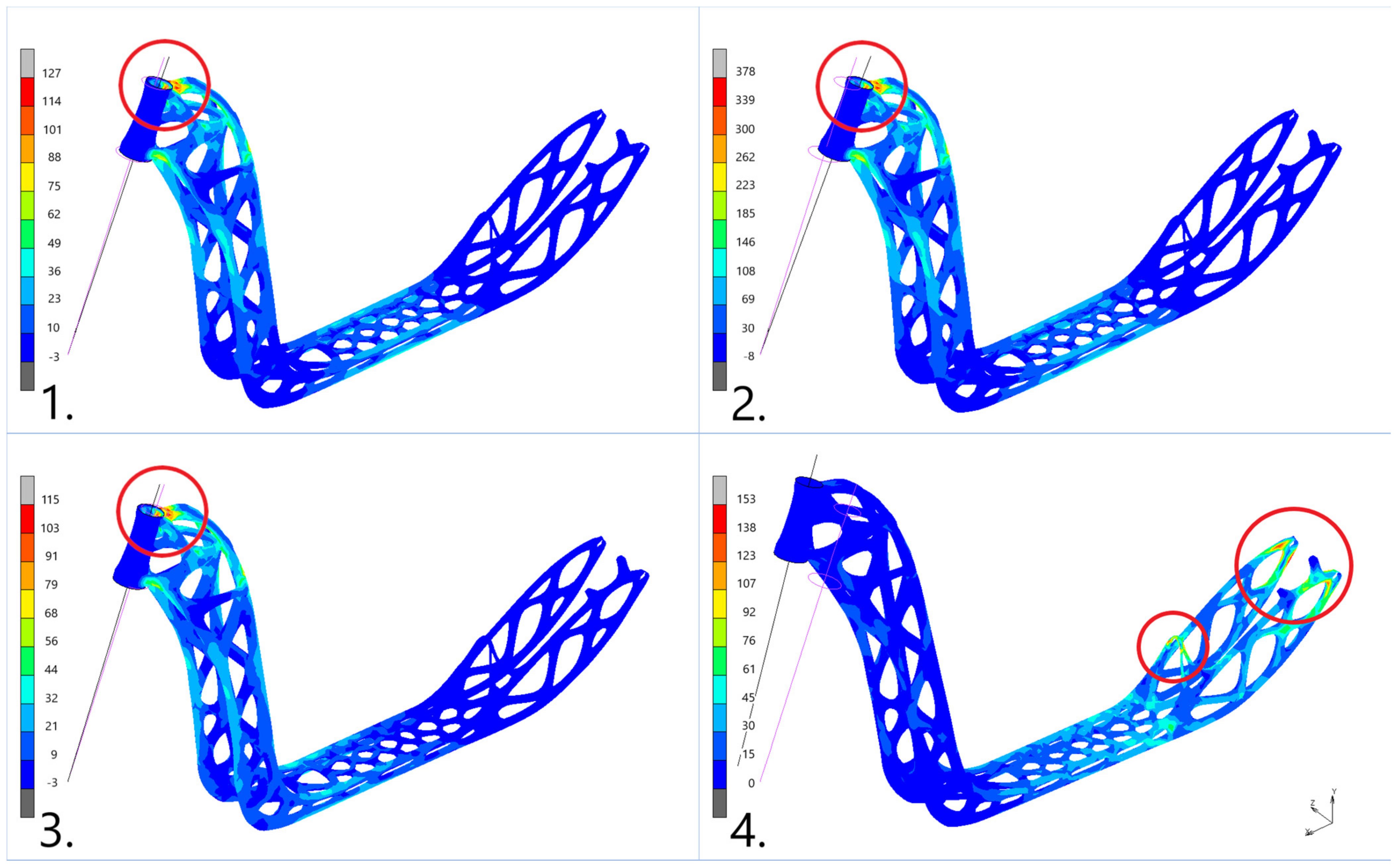
2.4. Finite Element Analysis (FEA)
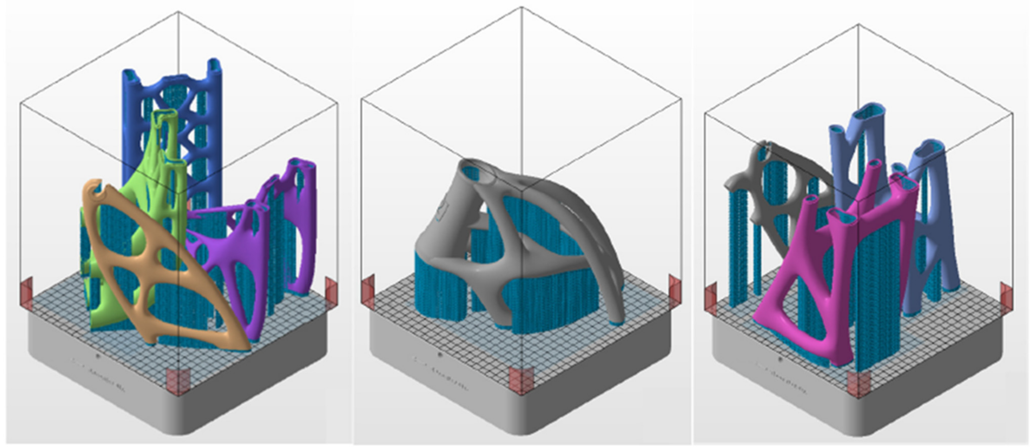
FEA of the whole frame was carried out utilizing the properties of the 3D printed 316L presented in Table 1. In particular, linear simulations were done, and the Von Mises (VM) criterion was used. The deflection and maximum VM stress level of the frame were recorded together with the factor of safety (FoS), calculated as yield strength divided by the maximum VM stress. Additionally, for the FEA model, shell elements were utilized with an assigned thickness of 1.2 mm. The whole frame was assumed to be continuous, i.e., without the existence of the weldments between frame sections, to simplify the modeling process. This assumption was made given that the size of the fitting feature was negligible, and the strength of the weldment was equivalent to that of the parent material, as presented in [44]. There were four simulations corresponding to the four aforementioned load cases. The FEA studies were done using Marc Mentat; the displacement results are fivefold magnified and the original shape of the frame is illustrated in Figure 8 for a better understanding of the load case effects.
As can be observed for normal operation, (1) in Figure 8, the force exerted by the 80 kg driver on the frame caused a maximum VM stress of 127 MPa, FoS of 3.7, and maximum step board deflection of 1.3 mm in the Oy direction. In the drop situation, (2) in Figure 8, these values were respectively 378 MPa, 1.2, and 3.8 mm. In the braking situation, (3) in Figure 8, the fork neck experienced the most severe VM stress of 115 MPa, with an FoS of 4.1. Eventually, under the torsional stiffness simulation, (4) in Figure 8, the most severely loaded area was the rear fork, i.e., the area near the rear wheel, with a maximum VM stress of 153 MPa, FoS of 3.1, and maximum fork neck deflection of 21 mm in the Oz direction. The simulation results show a significant improvement in comparison with the conventional frame in terms of the frame deflection. After fabrication, physical tests were carried out to verify the simulation results.

2.5. Manufacturing

2.5.1. 3D Printing

The machine Renishaw AM400 was deployed to fabricate the sectioned frame with the printing parameters in Table 2, following [42].
The STL files of the frame sections were imported into Autodesk Netfabb for component distribution on the building platform, support creation, and slicing operation to prepare for printing. Having considered the aforementioned size constraints of the building chamber, the distribution of the frame sections along with their supports could be realized, as presented in Figure 9.
There were three builds in total, for which the default SLM support type was chosen, and the critical angle for supports was 35°. The sections were distributed given that the end with higher mass of material would be nearer to the building platform. This was done to aid the supports to sufficiently transfer the excess heat from the builds to the platform, so as to avoid the shape distortion on top of the printed components due to overheating. Furthermore, the section orientation was done to minimize the roughness given the finding that the maximum roughness Sz increased with the increase in printing angle [6]. The fork neck was printed separately owing to its outstanding volume and the number of supports used. A number of supports were utilized to aid the building of hollowed profiles, which could not be manually removed from outside; hence, they were left as is after printing. These unremoved supports added weight with a negligible stiffening effect to the frame. After printing and support removal, the frame sections were processed further for welding.

2.5.2. Welding

The eight frame sections were assembled utilizing 141 tungsten inert gas (TIG) welding with a 1.6 mm diameter WLa15 electrode, and a 1.6 mm diameter wire made of 316 LSi EN 12072-19 12 3 was deployed as the filling material. The welded joints together with the assembled frame were subsequently manually ground to remove the excess filling material and to obtain better surface finishing for later painting. The assembled frame was finally inspected with 3D scanning for the surface deviation.

2.6. Geometric Inspection

The TO frame was 3D scanned for geometry inspection using Creaform Handyscan Black, with software VXElements and Geomagic Control X. Geometry inspection on the subsections was not performed because it was more appropriate to consider the assembled frame, whose overall geometry would affect the functionality of the scooter. Accordingly, the geometric accuracy of the 3D scanned assembled frame in comparison with its CAD counterpart by means of surface deviation is illustrated in Figure 10.
To the right side of the Figure 10, there is a contour bar representing the surface deviation of the assembled frame in mm with the red color indicating deflection out of the reference surfaces and the blue color indicating the opposite. In general, most of the physical frame deviated from −1 mm to 1 mm in comparison with the CAD model. Furthermore, the front of the frame deflected the least (−3 mm), and the rear fork bent counterclockwise around the rear transition with a maximum deflection of 3 mm, which could affect the positions of the front and the back wheels. Since regular waviness and negligible deviations can be achieved with SLM technology, as studied in [45], the outstanding shape deviation in the rear fork was more likely caused by imperfect welding operation since the fitting feature was situated at the rear transition, around which the rear fork is bent upward. Eventually, the TO frame was compared with the conventional one to see whether improvements were achieved.

2.7. Comparison with the Conventional Frame

After fabrication, the TO frame was put under the same performance tests as described in Section 2. The results were recorded and then compared with the conventional frame in the below Table 3.
It can be seen from Table 3 that the TO frame was 16% heavier than the conventional one (0.45 kg), 10% heavier than in the simulation. This weight gain from the simulation was due to the unremoved supports inside the hollowed profile. In terms of the deflection in normal operation and torsional stiffness, the TO frame was equivalent to its conventional counterpart. As for the simulation results, the deflection was incomparable with the real measurement, possibly due to the idealization of the fixation in the simulation, i.e., the usage of rigid elements, RBE2, to represent the fork, front, and back wheels, whereas, in reality, the scooter sits on two rubber wheels and is assembled with a deformable fork. Another drawback is that the VM stress level on the scooter under different load cases was not confirmed. The simulation results, however, showed reasonable deflecting shapes with highly stressed regions, which could be used as a reference for stress measurements. Additionally, to improve the correlation between the simulation results and reality, instead of the rigid elements, the real fork and its connection with the fork neck could be modeled to better represent the reality. Furthermore, a special stand can be designed to mount the frame to exclude the deformation of the wheels upon testing.

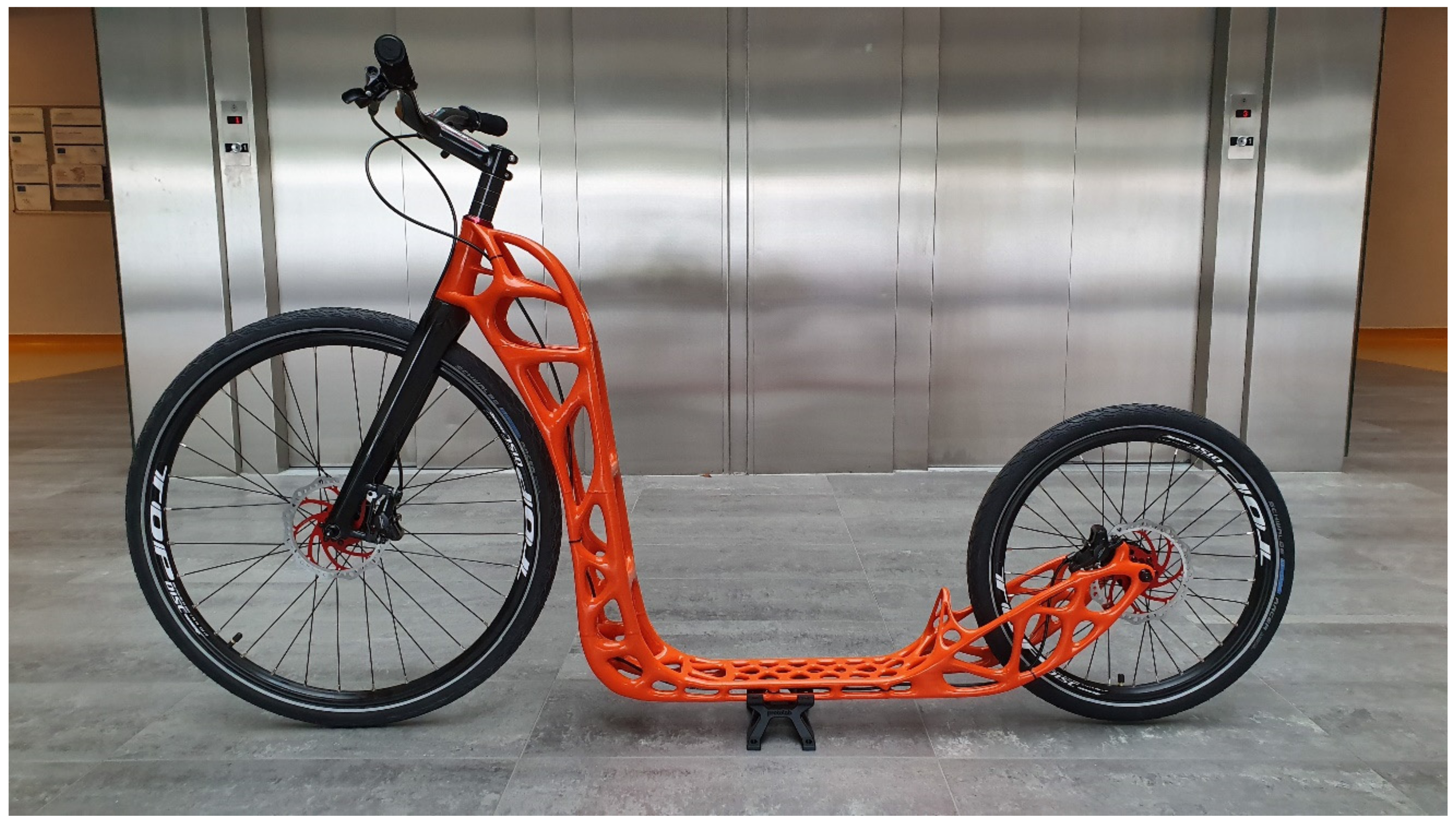
2.8. Fully Assembled TO Frame

The fully assembled TO frame is shown in Figure 11.
Except for the orange-painted TO frame, the other components were commercially available ones. This study showcases the completed TO workflow and associated improvements.

3. Conclusions

To the best of our knowledge, this study presents the first metallic TO scooter to be 3D printed, effectively establishing its potential. The manuscript showcases a typical framework for designing and manufacturing with TO. Remarkably, the limited space of the building chamber was not a restriction for printing over-dimensioned parts, i.e., the scooter frame, as special fitting features and welding could be utilized for later assembly. Indeed, the printed TO frame was functional, with a unique bionic shape. For future studies, it is possible to consider geometry compensation to pre-deform the CAD models such that the printed ones would spring back to their correct shapes, to prevent the shape distortion in advance. The residual stress can be reduced by varying the printing parameters and scanning strategies following [46]. Moreover, heat treatment can be utilized to further minimize the residual stress inherited from the printing process for better functionality and weldability, thus improving the material properties if carried out appropriately [47]. Regarding the supports, the printing orientation of the parts in the building chamber can be optimized for lower shape distortion and more efficient support usage, which would simplify the subsequent support removal process. Better orientation planning for easier support removal, together with thickness reduction, redesigning, and a better TO process, with insights gained from [48], could be effective ways to reduce the weight of the frame. In terms of FEM analysis, more realistic components instead of rigid elements can be modeled to avoid over-stiffened models, and special stands can be designed for testing the real scooter to exclude unwanted deformation. Furthermore, it should be noted that these findings can be considered for but are not limited to 3D printing scooter frames, as problems with 3D printing metals are indeed universal.

Author Contributions

Conceptualization, J.M. and L.J.; methodology, L.J.; software, J.M. and Q.-P.M.; investigation, J.M., L.J., Q.-P.M., J.H. and P.K.; writing—original draft preparation Q.-P.M.; writing—review and editing, Q.-P.M. and L.J.; visualization, J.H.; supervision, M.P.; project administration, T.T.; funding acquisition, M.P. All authors have read and agreed to the published version of the manuscript.

Funding

The study was done in connection with project “Innovative and additive manufacturing technology: new technological solutions for 3D printing of metals and composite materials”, reg. no. CZ.02.1.01/0.0/0.0/17_049/0008407, financed by the Structural and Investment Funds of the European Union. In addition, it is associated with project “Education system for personal resource development and research in the field of modern trend of surface engineering surface integrity”, reg. no. CZ.1.07/2.3.00/20.0037, financed by Structural Funds of the European Union, as well as by the means of the state budget of the Czech Republic, and with project “Students Grant Competition” SP2021/100, financed by the Ministry of Education, Youth, and Sports and the Faculty of Mechanical Engineering VŠB-TUO.

Institutional Review Board Statement

Not applicable.

Informed Consent Statement

Not applicable.

Data Availability Statement

Not applicable.

Acknowledgments

The authors would like to thank Advanced Engineering s.r.o. for support in the topology optimization study.

Conflicts of Interest

The authors declare no conflict of interest.

References

  1. Ngo, T.D.; Kashani, A.; Imbalzano, G.; Nguyen, K.T.Q.; Hui, D. Additive manufacturing (3D printing): A review of materials, methods, applications and challenges. Compos. Part B Eng. 2018, 143, 172–196. [Google Scholar] [CrossRef]
  2. Gibson, I.; Rosen, D.; Stucker, B. Additive Manufacturing Technologies: Rapid Prototyping to Direct Digital Manufacturing; Springer: New York, NY, USA, 2010; 459p, ISBN 1441911200. [Google Scholar]
  3. Červinek, O.; Werner, B.; Koutný, D.; Vaverka, O.; Pantělejev, L.; Paloušek, D. Computational Approaches of Quasi-Static Compression Loading of SS316L Lattice Structures Made by Selective Laser Melting. Materials 2021, 14, 2462. [Google Scholar] [CrossRef] [PubMed]
  4. Podroužek, J.; Marcon, M.; Ninčević, K.; Wan-Wendner, R. Bio-Inspired 3D Infill Patterns for Additive Manufacturing and Structural Applications. Materials 2019, 12, 499. [Google Scholar] [CrossRef] [Green Version]
  5. Pokorný, P.; Václav, Š.; Petru, J.; Kritikos, M. Porosity Analysis of Additive Manufactured Parts Using CAQ Technology. Materials 2021, 14, 1142. [Google Scholar] [CrossRef]
  6. Gogolewski, D.; Bartkowiak, T.; Kozior, T.; Zmarzły, P. Multiscale Analysis of Surface Texture Quality of Models Manufactured by Laser Powder-Bed Fusion Technology and Machining from 316L Steel. Materials 2021, 14, 2794. [Google Scholar] [CrossRef]
  7. DebRoy, T.; Wei, H.L.; Zuback, J.S.; Mukherjee, T.; Elmer, J.W.; Milewski, J.O.; Beese, A.M.; Wilson-Heid, A.; De, A.; Zhang, W. Additive manufacturing of metallic components—Process, structure and properties. Prog. Mater. Sci. 2018, 92, 112–224. [Google Scholar] [CrossRef]
  8. Pagac, M.; Hajnys, J.; Halama, R.; Aldabash, T.; Mesicek, J.; Jancar, L.; Jansa, J. Prediction of model distortion by FEM in 3D printing via the selective laser melting of stainless steel AISI 316l. Appl. Sci. 2021, 11, 1656. [Google Scholar] [CrossRef]
  9. Nickels, L. 3D printing the world’s first metal bicycle frame. Met. Powder Rep. 2014, 69, 38–40. [Google Scholar] [CrossRef]
  10. Abdi, M.; Ashcroft, I.; Wildman, R. Design optimisation for an additively manufactured automotive component. Int. J. Powertrains 2018, 7, 142. [Google Scholar] [CrossRef]
  11. Ferro, C.G.; Varetti, S.; De Pasquale, G.; Maggiore, P. Lattice structured impact absorber with embedded anti-icing system for aircraft wings fabricated with additive SLM process. Mater. Today Commun. 2018, 15, 185–189. [Google Scholar] [CrossRef]
  12. Hodonou, C.; Balazinski, M.; Brochu, M.; Mascle, C. Material-design-process selection methodology for aircraft structural components: Application to additive vs subtractive manufacturing processes. Int. J. Adv. Manuf. Technol. 2019, 103, 1509–1517. [Google Scholar] [CrossRef]
  13. Yan, S.N.; Li, B.; Hong, J. Bionic design and verification of high-precision machine tool structures. Int. J. Adv. Manuf. Technol. 2015, 81, 73–85. [Google Scholar] [CrossRef]
  14. Liu, J.; Ou, H.; He, J.; Wen, G. Topological Design of a Lightweight Sandwich Aircraft Spoiler. Materials 2019, 12, 3225. [Google Scholar] [CrossRef] [PubMed] [Green Version]
  15. Yang, Y.; Xin, X.; Bin, Z.; Wei, Z.; Yidi, W. Bionic design for the aerodynamic shape of a stratospheric airship. Aerosp. Sci. Technol. 2020, 98, 105664. [Google Scholar] [CrossRef]
  16. Kong, D.; Ni, X.; Dong, C.; Lei, X.; Zhang, L.; Man, C.; Yao, J.; Cheng, X.; Li, X. Bio-functional and anti-corrosive 3D printing 316L stainless steel fabricated by selective laser melting. Mater. Des. 2018, 152, 88–101. [Google Scholar] [CrossRef]
  17. Hlinka, J.; Kraus, M.; Hajnys, J.; Pagac, M.; Petru, J.; Brytan, Z.; Tanski, T. Complex corrosion properties of AISI 316L steel prepared by 3D printing technology for possible implant applications. Materials 2020, 13, 1527. [Google Scholar] [CrossRef] [Green Version]
  18. Bendsoe, M.P.; Sigmund, O. Topology Optimization: Theory, Methods and Applications; Springer: Berlin/Heidelberg, Germany, 2003; ISBN 3-540-42992-1. [Google Scholar]
  19. Liu, Y.; Li, Z.; Wei, P.; Chen, S. Generating support structures for additive manufacturing with continuum topology optimization methods. Rapid Prototyp. J. 2019, 25, 232–246. [Google Scholar] [CrossRef]
  20. Jiang, L.; Ye, H.; Zhou, C.; Chen, S. Parametric Topology Optimization Toward Rational Design and Efficient Prefabrication for Additive Manufacturing. J. Manuf. Sci. Eng. Trans. ASME 2019, 141, 041007. [Google Scholar]
  21. Jiang, D.; Hoglund, R.; Smith, D.E. Continuous Fiber Angle Topology Optimization for Polymer Composite Deposition Additive Manufacturing Applications. Fibers 2019, 7, 14. [Google Scholar] [CrossRef] [Green Version]
  22. Zhu, D.; Zhan, W.; Wu, F.; Simeone, A. Topology Optimization of Spatially Compliant Mechanisms with an Isomorphic Matrix of a 3-UPC Type Parallel Prototype Manipulator. Micromachines 2018, 9, 184. [Google Scholar] [CrossRef] [Green Version]
  23. Garaigordobil, A.; Ansola, R.; Veguería, E.; Fernandez, I. Overhang constraint for topology optimization of self-supported compliant mechanisms considering additive manufacturing. Comput. Aided Des. 2019, 110, 33–48. [Google Scholar] [CrossRef]
  24. Zhu, J.; Zhou, H.; Wang, C.; Zhou, L.; Yuan, S.; Zhang, W. A review of topology optimization for additive manufacturing: Status and challenges. Chin. J. Aeronaut. 2021, 34, 91–110. [Google Scholar] [CrossRef]
  25. Bendsøe, M.P.; Sigmund, O. Topology optimization by distribution of isotropic material. In Topology Optimization; Springer: Berlin/Heidelberg, Germany, 2004. [Google Scholar] [CrossRef]
  26. Junk, S.; Klerch, B.; Nasdala, L.; Hochberg, U. Topology optimization for additive manufacturing using a component of a humanoid robot. Procedia CIRP 2018, 70, 102–107. [Google Scholar] [CrossRef]
  27. Orme, M.; Madera, I.; Gschweitl, M.; Ferrari, M. Topology optimization for additive manufacturing as an enabler for light weight flight hardware. Designs 2018, 2, 51. [Google Scholar] [CrossRef] [Green Version]
  28. Sadri, M.; Kavandi, M.; Jozepiri, A.; Teimouri, S.; Abbasi, F. Bionic Architecture, Forms and Constructions. Res. J. Recent Sci. 2014, 3, 93–98. [Google Scholar]
  29. Ding, Y.; Zhou, Z.; Wang, Z.; Liu, H.; Wang, K. Bionic Stiffener Layout Optimization with a Flexible Plate in Solar-Powered UAV Surface Structure Design. Appl. Sci. 2019, 9, 5196. [Google Scholar] [CrossRef] [Green Version]
  30. Warguła, Ł.; Wojtkowiak, D.; Kukla, M.; Talaśka, K. Symmetric Nature of Stress Distribution in the Elastic-Plastic Range of Pinus, L. Pine Wood Samples Determined Experimentally and Using the Finite Element Method (FEM). Symmetry 2021, 13, 39. [Google Scholar] [CrossRef]
  31. Christiansen, A.N.; Bærentzen, J.A.; Nobel-Jørgensen, M.; Aage, N.; Sigmund, O. Combined shape and topology optimization of 3D structures. Comput. Graph. 2015, 46, 25–35. [Google Scholar] [CrossRef] [Green Version]
  32. Wang, L.; Du, W.; He, P.; Yang, M. Topology Optimization and 3D Printing of Three-Branch Joints in Treelike Structures. J. Struct. Eng. 2020, 146, 04019167. [Google Scholar] [CrossRef]
  33. Primo, T.; Calabrese, M.; Del Prete, A.; Anglani, A. Additive manufacturing integration with topology optimization methodology for innovative product design. Int. J. Adv. Manuf. Technol. 2017, 93, 467–479. [Google Scholar] [CrossRef]
  34. Li, C.; Liu, J.F.; Guo, Y.B. Prediction of Residual Stress and Part Distortion in Selective Laser Melting. Procedia CIRP 2016, 45, 171–174. [Google Scholar] [CrossRef] [Green Version]
  35. Williams, R.; Catrin, J.; Davies, M.; Hooper, P.A. A pragmatic part scale model for residual stress and distortion prediction in powder bed fusion. Addit. Manuf. 2018, 22, 416–425. [Google Scholar] [CrossRef]
  36. The Project. Available online: http://www.3i-print.com/ (accessed on 28 June 2021).
  37. Significant Weight Reduction by Using Topology Optimization in Volkswagen Design Development. Available online: https://www.altair.com/resource/significant-weight-reduction-by-using-topology-optimization-in-volkswagen-design-development (accessed on 28 June 2021).
  38. BMW 3D Printing Superbike Components at the Track|3D-Prints. Available online: https://3d-prints.com/2020/11/04/bmw-3d-printing-superbike-components-at-the-track/ (accessed on 28 June 2021).
  39. Airbus APWorks Launches the ‘Light Rider’: The World’s First 3D-Printed Motorcycle. Available online: https://www.airbus.com/newsroom/press-releases/en/2016/05/APWorks-Launch-Light-Rider.html (accessed on 28 June 2021).
  40. Topology Optimization of Aircraft Wing Box Ribs. Available online: https://www.altair.com/resource/topology-optimization-of-aircraft-wing-box-ribs (accessed on 28 June 2021).
  41. Relativity Space. Available online: https://www.relativityspace.com/rockets (accessed on 28 June 2021).
  42. Hajnys, J.; Pagac, M.; Kotera, O.; Petru, J.; Scholz, S. Influence of basic process parameters on mechanical and internal properties of 316l steel in SLM process for RENISHAW AM400. MM Sci. J. 2019, 2019, 2790–2794. [Google Scholar] [CrossRef] [Green Version]
  43. Inspire 2018—Why Use PolyNURBS? Available online: https://www.altair.com/training/inspire_2018/content/polynurbs/why_polynurbs.htm (accessed on 7 May 2021).
  44. Mohyla, P.; Hajnys, J.; Sternadelová, K.; Krejčí, L.; Pagáč, M.; Konečná, K.; Krpec, P. Analysis of welded joint properties on an AISI316L stainless steel tube manufactured by SLM technology. Materials 2020, 13, 4362. [Google Scholar] [CrossRef] [PubMed]
  45. Kozior, T.; Bochnia, J.; Zmarzły, P.; Gogolewski, D.; Mathia, T. Waviness of Freeform Surface Characterizations from Austenitic Stainless Steel (316 L) Manufactured by 3D Printing-Selective Laser Melting (SLM) Technology. Materials 2020, 13, 4372. [Google Scholar] [CrossRef]
  46. Hajnys, J.; Pagáč, M.; Měsíček, J.; Petru, J.; Król, M. Influence of Scanning Strategy Parameters on Residual Stress in the SLM Process According to the Bridge Curvature Method for AISI 316L Stainless Steel. Materials 2020, 13, 1659. [Google Scholar] [CrossRef] [Green Version]
  47. Chen, N.; Ma, G.; Zhu, W.; Godfrey, A.; Shen, Z.; Wu, G.; Huang, X. Enhancement of an additive-manufactured austenitic stainless steel by post-manufacture heat-treatment. Mater. Sci. Eng. A 2019, 759, 65–69. [Google Scholar] [CrossRef]
  48. Sotola, M.; Marsalek, P.; Rybansky, D.; Fusek, M.; Gabriel, D. Sensitivity Analysis of Key Formulations of Topology Optimization on an Example of Cantilever Bending Beam. Symmetry 2021, 13, 712. [Google Scholar] [CrossRef]
Figure 1. TO workflow.
Symmetry 13 01201 g001
Figure 2. Conventional frame with anticipated weak spots circled.
Symmetry 13 01201 g002
Figure 3. Conventional frame with circled weak spots.
Symmetry 13 01201 g003
Figure 4. TO results in four load cases with according boundary conditions: (1) normal operation, (2) drop, (3) braking, and (4) torsional stiffness.
Symmetry 13 01201 g004
Figure 5. Solid redesigned scooter frame: (1) side view, (2) front view, (3) top view, and (4) isometric view.
Symmetry 13 01201 g005
Figure 6. Sectioned solid redesigned scooter frame.
Symmetry 13 01201 g006
Figure 7. Hollowed sections with fitting feature designed for welding operation.
Symmetry 13 01201 g007
Figure 8. FEA results in four load cases: (1) normal operation, (2) drop, (3) braking, and (4) torsional stiffness.
Symmetry 13 01201 g008
Figure 9. Distribution of frame sections on the building platform.
Symmetry 13 01201 g009
Figure 10. Surface deviation result of the TO frame from 3D scanning.
Symmetry 13 01201 g010
Figure 11. Fully assembled TO scooter frame.
Symmetry 13 01201 g011
Table 1. Mechanical properties of the 3D printed stainless steel 316L.
ParameterValue
Density7.99 × 10−6 kg·mm−3
Tensile strength614 MPa
Yield strength (0.2% offset)467 MPa
Young modulus204 GPa
Poisson’s ratio0.29
Table 2. Printing parameters.
ParameterValue
StrategyMeander
Laser power200 W
Layer thickness50 µm
Hatch spacing0.11 mm
Scan speed650 mm/s
Table 3. Comparison between the conventional and the TO frame.
ConventionalTO%
SimulationReality
Weight4.4 kg4.65 kg5.10 kg+0.16
Normal operationDeflection11 mm1.3 mm11 mm0
VM stress--127 MPa----
DropDeflection--3.8 mm----
VM stress--378 MPa----
BrakingDeflection--------
VM stress--115 MPa--
Torsional stiffnessDeflection30 mm21 mm30 mm0
VM stress--153 MPa----
Publisher’s Note: MDPI stays neutral with regard to jurisdictional claims in published maps and institutional affiliations.

