Abstract
In view of the lack of image enhancement processing in the traditional methods in image preprocessing, which leads to a long detection time for internal cracks in the image and poor visual effects, an intelligent detection method for internal cracks in aircraft landing gear images under multimedia processing is proposed. A spatial index structure is established based on the multimedia database, and the aircraft landing gear images in the structure are enhanced and denoised. Image segmentation is performed according to the preprocessing results, the crack foreground and the road surface background in the image are separated, and the threshold value of each image is calculated. The threshold segmentation result is used to distinguish which pixels are the areas where the cracks may exist and which pixels belong to the image background, and the judgment result realizes crack detection. The experimental results show that the crack detection time of the proposed method is shorter, the visual effect of the detection results is better, and the average of the expert score reaches 93.6 points, which verifies the effectiveness of the proposed method from both the subjective and objective aspects.
1. Introduction
As the landing gear of aircraft has the characteristics of severe stress, poor working environment, and high failure rate, the image recognition of aircraft landing gear cracks has always been a research hotspot at home and abroad [1,2,3]. The traditional image crack detection method is mainly to identify the information contained in the image, which has certain limitations, and the image crack detection requires multiple comparisons of image features during the detection process, and the detection process is more cumbersome [4]. In view of the problems of the traditional methods, related scholars have conducted extensive research on image crack detection from different levels, and obtained numerous research results.
Chisholm et al. propose an FPGA-based particle filter real-time crack detection method, which transmits all applicable sensor data to the ground station, which will be detected later. The crack detection particle filter is optimized based on FPGA, and parallel calculation is performed. The experimental results show that this method has obvious advantages in terms of the calculation speed and space occupation, but it has shortcomings in terms of the visual effects [5]. Kaddah et al. propose a new algorithm for extracting cracks from two-dimensional pavement images. The road condition information is an important part of the road management system. Accurately extracting road degradation, especially cracks, is a key task for road safety. Relying on the luminosity and geometric characteristics of the cracks, edge detection technology is used to avoid the unfavorable conditions of image acquisition, verify whether there is a high concentration of cracked pixels, finally, confirm whether there are cracks in the image through the results obtained by refinement. The experimental results show that the method can provide more accurate detection results for two-dimensional road images without supervision. However, because the problem of image denoising is not considered, the edge information of the cracked image is blurred [6]. Yang et al. proposed an algorithm for oil pipe crack detection based on improved median filtering and morphology [7]. First, the improved median filter was used to denoise the image, and then the image was wavelet decomposed and processed by the wavelet modulus maximum method. While processing high frequency components, the improved morphology is used to detect cracks in low frequency components. Finally, the high and low frequency cracks were integrated, and the detected cracks were filtered according to the rectangularity. The experimental results show that, compared with the morphological method or wavelet modulus maximum method alone, this algorithm can better suppress noise while ensuring the continuity of tubing cracks and improve the detection effect, but this method also has a longer detection time problem, so the test result is not perfect.
In view of the poor visual effect of the traditional method, the fuzzy edge information of the crack image and the long detection time, with the help of multimedia data indexing technology, an intelligent detection method for the internal crack of the aircraft landing gear image is proposed. Existing multimedia database indexing technology generally cannot adapt to the search of multidimensional spatial attributes, especially the content retrieval of large-capacity images. Therefore, this article uses the index structure of the multimedia database to index the aircraft landing gear images. On this basis, the aircraft landing gear images are preliminarily processed through image preprocessing steps such as image enhancement and image denoising, and then the images of the different cracks are analyzed. The intelligent detection of internal cracks in landing gear image is realized by using insert detection. In the second part of this paper, the overall framework of the intelligent detection of internal cracks in aircraft landing gear image is constructed, and the aircraft landing gear image is preprocessed to realize the intelligent detection of internal cracks in aircraft landing gear. In the third part, the experiment is carried out.
2. Intelligent Detection Method for Internal Cracks in Aircraft Landing Gear Images
In this part, the overall framework of the intelligent detection of internal cracks in aircraft landing gear images is constructed, the spatial index structure of the multimedia database is proposed, and the image of the aircraft landing gear is preprocessed, so as to realize the intelligent detection of internal cracks in the aircraft landing gear.
2.1. The Overall Framework for Intelligent Detection of Internal Cracks in Aircraft Landing Gear Images
Although a wealth of in the field of aircraft fatigue detection at home and abroad, aircraft landing gear fatigue accidents caused by aircraft landing gear crack failures still occur from time to time. The main reasons are the high cost and long cycle of the landing gear fatigue test, which makes it difficult to apply the theoretical research results in practice [8]. Therefore, by designing image crack detection methods, the safety factor of the landing gear products is improved. Figure 1 is the overall frame diagram of the intelligent detection of internal cracks in aircraft landing gear images.
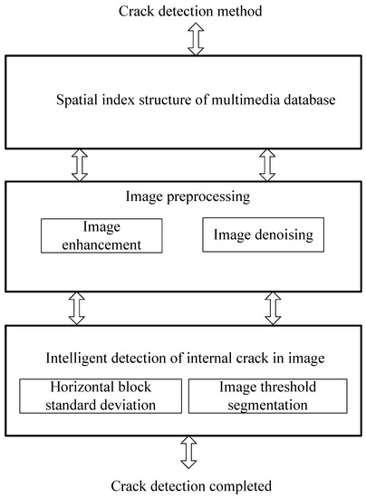
Figure 1.
The overall frame diagram of the intelligent detection of internal cracks in the aircraft landing gear image.
It can be seen from Figure 1 that the content of this article is mainly divided into three main parts, namely: multimedia database spatial retrieval design, image preprocessing and crack detection. From these three main aspects, the research content of image crack detection of the aircraft landing gear is explained. In order to achieve the goal of image detection of aircraft landing gear crack.
2.2. Spatial Index Structure of Multimedia Database
In the multimedia database, it is necessary to adopt appropriate indexing technology to cooperate with the retrieval engine of the multimedia database to greatly improve the efficiency of the query. Indexing technology has been successfully applied to most relational database systems. Unlike other types of databases, multimedia databases need to adopt multidimensional indexing technology [9]. For aircraft landing gear images, multidimensional indexing is performed on multiple attributes of the image, and one index structure is used to retrieve multiple attributes, which can greatly shorten the response time. In addition, for the index of complex images, fixed-grid can be used to improve retrieval efficiency [10].
Fixed-grid is a multidimensional index structure which divides the multidimensional space into grids of the same size. These fixed-size grids are represented by multidimensional arrays. The data in the same grid are connected in series with a dynamic structure similar to a linked list. Since the divided grid size has been set in advance, it has nothing to do with the input data, resulting in the uneven distribution of the data across the entire storage space. Some grids have no data, while other grids may have a lot of data [11]. In order to improve the retrieval efficiency using the grid structure, a simple one-dimensional array can be used to establish a corresponding scale table for each attribute of the multidimensional data according to the size of the divided grid, so as to quickly locate the grid where the data to be retrieved are located. Although one more index structure is created in this way, the time is greatly reduced.
2.3. Image Preprocessing of Aircraft Landing Gear
The preprocessing of the landing gear image, including image enhancement and image denoising, is described in detail below.
2.3.1. Image Enhancement of Aircraft Landing Gear
The overall pixel intensity of the image is too small, which is not conducive to the crack detection in the image, and the higher brightness of the local area in the image will increase the local pixel intensity of the image, which is not conducive to the crack detection of the pavement aircraft landing gear image. In order to reduce this adverse effect, the image of the landing gear of the aircraft should be enhanced first. At present, many scholars have conducted research on image enhancement and have achieved fruitful results. The mainstream algorithms currently used in image enhancement include the mean filtering algorithm, median filtering algorithm, adaptive median filtering algorithm, and wavelet transform image enhancement algorithm. Based on the existing image enhancement algorithms, this section uses morphology to optimize the existing image enhancement algorithms.
The image enhancement method of aircraft landing gear based on morphology can be described as:
- (1)
- Obtain the pixel value of each edge point in the image according to the following formula [12]:
- (2)
- The weight of each point is calculated according to the gradient of each point, and the maximum value of is set to . The greater the gradient of the point in the image, the greater the probability that it belongs to the edge. Then, the weight of the point with gradient (representing the degree of membership belonging to the edge) is:
- (3)
- Use weighted mean filtering to prevent edge distortion and noise amplification caused by pure morphological sharpening. The calculation method of the image edge distortion function is as follows:
Mean filtering is a kind of linear filtering algorithm, which means that the target pixel is given a template on the image, which includes the adjacent pixels around it, and then the average value of all the pixels in the template is used to replace the original pixel value, so as to enhance the image. The template is shown in Formula (4):
where represents the near pixel; represents the average of all pixels.
Through image enhancement processing, the problem of high brightness in the local area of the image is solved. However, due to the influence of noise in the image, the gray jump of the image will occur, which changes the local continuity of the image [13]. Therefore, it is necessary to denoise the aircraft landing gear image.
2.3.2. Image Denoising of Aircraft Landing Gear
As some noise points will be included in the image, the existence of the noise points will affect the accuracy of subsequent detection of the image. At the same time, in order to avoid the local continuous nature of the aircraft landing gear image from being changed, it is necessary to filter out the cracks in the image noise. The hyperspectral sensor is used to obtain the hyperspectral image of the aircraft landing gear, and the acquired hyperspectral image is denoised, which provides relevant information for the intelligent detection of internal cracks in the aircraft landing gear image [14].
A sparse representation of the aircraft’s landing gear image is performed by three-dimensional DCT to achieve image denoising. Three dimensional DCT transform function is described by the following formula:
where represents the gray value of the aircraft landing gear image; represents the band sequence number; represents the width corresponding to the image; represents the length corresponding to the image; represents the number of the band sequence.
The product of the dimensional column vector and the matrix is used to represent the calculation of multidimensional DCT. Assuming that represents the transformation matrix of one-dimensional DCT, the three-dimensional DCT dictionary corresponding to the aircraft landing gear image can be described as:
where represents a complete dictionary; and represent image blocks of aircraft landing gear.
According to the above analysis, the denoising process of the aircraft landing gear images based on hyperspectral sensors is as follows:
(1) Initialize the aircraft landing gear after image enhancement.
(2) Establishe a complete dictionary , divide the image blocks of aircraft landing gear, and sort the image blocks to obtain the row vector and column vector of the image.
(3) Solve the sparse coefficients based on the over-complete dictionary and one-dimensional DCT transformation matrix through the orthogonal matching pursuit algorithm [15].
(4) Traditional denoising algorithms only consider the recovery of image information from noisy images, but the use of residual signals after denoising has not been paid attention to. In view of the characteristic that the residual signal contains useful information after image denoising, the residual signal function is used to set and update the residual error:
where represents a single noisy image; represents the screening result of the residual image blocks after the first noise reduction.
(5) Based on the one-dimensional transformation matrix , the dimension matrix is updated until the following boundary condition formula is satisfied:
where represents the spatial domain analysis of the crack damage inside the aircraft landing gear image.
(6) Replace each column of matrix with the stereoscopic image of .
(7) Combine the image blocks and take the average of the overlapping image blocks to obtain the denoised aircraft landing gear image cube .
According to the above analysis, the denoising process of the aircraft landing gear image based on the hyperspectral sensor is represented by the flowchart shown in Figure 2.
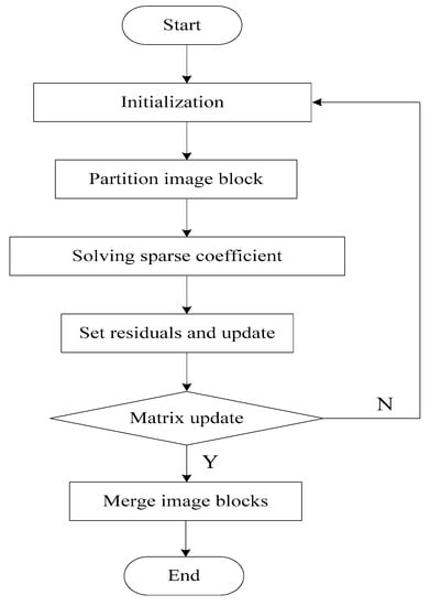
Figure 2.
Image denoising flowchart.
2.4. Implementation of Intelligent Detection of Internal Cracks in Aircraft Landing Gear Images
The ultimate goal of crack image detection is to detect crack pixels in the image. After image preprocessing, the foreground contrast of the crack image is enhanced, and noise is effectively suppressed. Therefore, in the image, the pixels whose pixel intensity is lower than most pixels can be regarded as crack pixels. Based on the image preprocessing, the cracks in the image are detected. In the process of the intelligent detection of internal cracks in aircraft landing gear images, the preprocessed image must be image segmented to separate the crack foreground and pavement background in the image. Calculate the threshold of each image to distinguish which pixels are the areas where cracks may exist and which pixels belong to the image background [16]. After the image segmentation process obtains the area where the crack may exist, then the crack pixel is determined for the crack candidate area.
The image is divided into image blocks according to the appropriate width and height values. The standard deviation of the horizontal block can be represented by a coordinate graph. The abscissa graph is the serial number of the image block number in the height direction, and the ordinate is the sub-block in the horizontal direction. The standard deviation of image pixel intensity [17]. Figure 3 is the horizontal block standard deviation of the transverse cracks in the aircraft landing gear image.
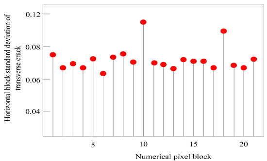
Figure 3.
Horizontal block standard deviation of transverse cracks in aircraft landing gear image.
Similar to the definition of horizontal block standard deviation, the definition of the vertical block standard deviation is given: after the image is divided into blocks, the standard deviation of the subimage pixel intensity in the vertical direction is called the vertical block standard of the image difference. The vertical block standard deviation can be represented by a coordinate graph, where the abscissa graph is the serial number of the number of image blocks in the width direction, and the ordinate is the standard deviation of the subimage pixel intensity in the vertical direction. Figure 4 is the standard deviation of the vertical block of the transverse cracks in the aircraft landing gear image.
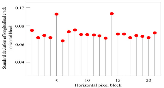
Figure 4.
Standard deviation of vertical block of transverse cracks in aircraft landing gear image.
The pixel intensity standard deviation shows the intensity of the pixel intensity change in the block. The larger the standard deviation, the greater the pixel intensity change in the block. Due to the large difference between the intensity of the cracked pixels and the intensity of the background pixels, the standard deviation of the pixel intensity of a certain block in the cracked image is obviously greater than the standard deviation of the pixel intensity of the other blocks, so there is a possibility of cracks in this block [18]. It can be seen that the standard deviations of the two blocks with serial numbers 10 and 18 represented by the abscissa in Figure 3 are significantly larger than the standard deviations of the other blocks. Therefore, these two blocks are likely to be blocks with cracked pixels. The standard deviations of the two blocks with serial numbers 5 and 14 represented by the abscissa in Figure 4 are obviously greater than the standard deviations of the other blocks. Therefore, these two blocks are likely to be blocks with cracked pixels.
According to the analysis results of the standard deviation of the image block of the aircraft landing gear, the threshold segmentation method is further used to detect the image cracks [19,20,21]. Threshold segmentation is a method of directly segmenting the detected image target area. The basic idea is to segment the image into areas corresponding to the actual objects in the image according to the pixel intensity of the image. Within each region of the image after segmentation, from the perspective of pixel intensity, the pixel intensity is different between the different regions, and there are significant boundaries between regions with different pixel intensities. The essence of threshold segmentation is the transformation expressed by Formula (9):
where represents the output image; represents the segmentation threshold. According to Formula (9), it can be known that the background pixel in the image takes the value 0, and the foreground pixel takes the value 1.
In the image threshold segmentation algorithm, the important step is to find the appropriate threshold. After the threshold is obtained, it is compared with the pixel intensity value of each pixel in the image. After the segmentation, the separation result of the foreground region and the background region of the image is obtained directly.
According to the results of the image segmentation, the two-dimensional feature space of the crack type in the aircraft landing gear image is represented by Figure 5.
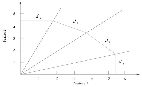
Figure 5.
Two-dimensional feature space of crack types.
In the two-dimensional feature space of the crack type in the image of the aircraft landing gear in Figure 5, represents the distance to the abscissa axis (representative feature 1: represents the standard deviation of pixel intensity in the vertical direction), and represents the distance to the ordinate axis (represents feature 2: represents the standard deviation of pixel intensity in the horizontal direction). represents the distance from a point in the feature space to the bisecting line (solid line) of the feature space, and the dotted line represents the positions of and .
In Figure 5, the oblique implementation divides the two-dimensional feature region into two parts, which means that the distribution probability of the points in the feature space in the two-dimensional feature space is the same, that is, the probability of the crack block connected region in the two regions is the same. The points located on the horizontal axis or the vertical axis in Figure 5 are completely standard transverse cracks and longitudinal cracks, respectively. Then, the probability that the crack type belongs to the transverse crack is calculated by Formula (10):
The probability that the crack type belongs to the longitudinal crack is calculated by Formula (11):
where and , respectively, represent the probability that the crack type is a transverse crack and a longitudinal crack. When one of these two probabilities is greater than 0.5, the crack type can be judged accordingly; represents the distance to the center oblique solid line; represents the split result of the connected component of the crack block: represents the coincidence area of the crack blocks; represents the maximum distance from the edge point to center of the transverse crack.
3. Simulation Experiment
In order to verify the effectiveness and comprehensiveness of the intelligent detection method for internal cracks in aircraft landing gear images under multimedia processing, simulation experiments are carried out. In the experiment, the crack extraction algorithm for two-dimensional road images proposed by Kaddah et al. [6] and the oil pipe crack detection algorithm based on improved median filtering and morphology proposed by Yang et al. [7] are selected as the comparison method, and the comparison is made from subjective and objective evaluation. The detection results are compared, and the comparison process and results are analyzed as follows [22,23].
3.1. Experimental Design
The nose landing gear of a certain type of aircraft is selected as the experimental object. The main parts of the landing gear include: 1. beam; 2. ear piece 122 (right); 3. ear piece 123 (left); 4. pillar; 5. middle joint; 6. (left and right) diagonal struts; 7. middle joint; 8. piston rod; 9. rod head; 10. front axle; 11. clamp; 12. front strut; 13. front strut joint; 14. (left and right) front support rod tube; 15. (left and right) front support joints; 16. upper torsion arm; 17. lower torsion arm; 18. front axle. The physical map of the landing gear is shown in Figure 6.
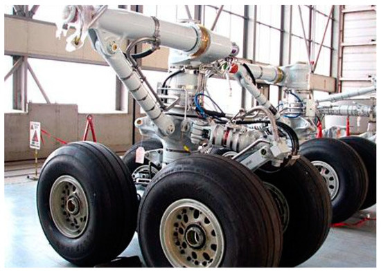
Figure 6.
Physical image of aircraft landing gear.
In the experiment, we try to keep the main body of the above components, and then omit the details that have little or no influence on the distribution of force. This can save modeling and experiment time, and ensure the accuracy of the landing gear stress response as much as possible.
3.2. Verification of Experimental Results
In order to verify the effectiveness of the proposed method, the experiment adopts the expert evaluation method to conduct a subjective evaluation of the proposed method. In order to highlight the advantages of the proposed method, we compare it with the expert evaluation results of the method proposed by Kaddah et al. [6] and the method proposed by Yang et al. [7]. The evaluation results of different methods by experts are shown in Table 1:

Table 1.
Experts’ evaluation results of different methods/point.
Analyzing the data results in Table 1, it can see that the average score of the expert evaluation result of the proposed method is 93.6, while the average score of the expert evaluation result of the method proposed by Kaddah et al. [6] is 84.4, and the average score of the expert evaluation result of the method proposed by Yang et al. [7] is 77.3. From the data in the table, it can be seen that the experts have a higher evaluation of the proposed method, indicating that the method has a better crack detection effect.
In order to further verify the effectiveness of the proposed method, Matlab 7.0 software is used for simulation experiments. Figure 7 is a schematic diagram of the comparison of the crack image edge detection between the proposed method and the method proposed by Kaddah et al. [6] and the method proposed by Yang et al. [7].
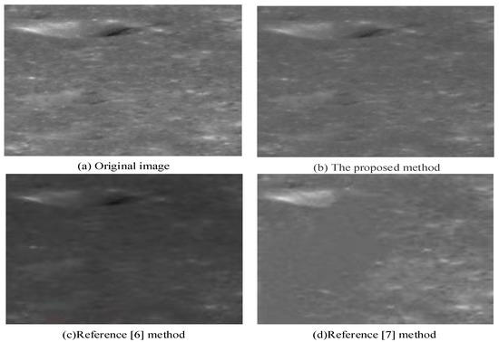
Figure 7.
Visual comparison of crack detection results of different methods [6,7].
It can be seen from Figure 7 that the method proposed by Kaddah et al. [6] is more sensitive to the internal details of the image cracks, but the image brightness is low, which affects the crack detection results. Although the method proposed by Yang et al. [7] maintains the brightness of the original image well, the accuracy of the crack edge location is poor, and the edge information is relatively fuzzy, which has a greater impact on the joint position detection of the landing gear crack, and does not highlight the target center in the image. In comparison, the proposed method can obtain more significant edge detection results, and minimize the formation of noise, so that the visual effects of cracked joints and linear characteristics are significantly improved.
The following uses the detection time as the experimental index to compare the crack detection effects of different methods, and the results are shown in Figure 8.
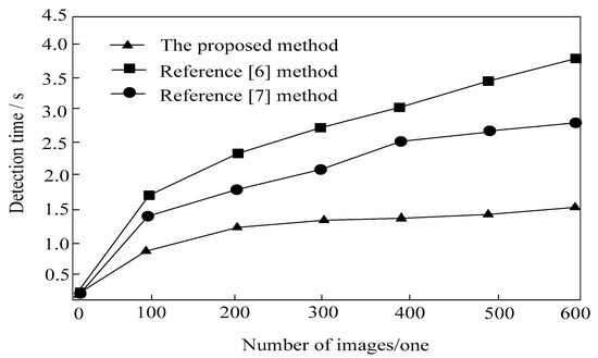
Figure 8.
Crack detection time comparison [6,7].
The analysis of Figure 8 shows that with the increase of the number of images, the detection time of the different methods shows a rising trend, but by comparison, the detection time of the proposed method is always lower than that of the traditional methods; this is because the method of this paper optimizes the existing image enhancement algorithm by morphology based on the existing image enhancement algorithm. The hyperspectral image of the aircraft landing gear is obtained by the hyperspectral sensor, and the hyperspectral image is denoised, which provides the relevant information for the intelligent detection of internal cracks in the aircraft landing gear image, which indicates that the detection time of the proposed method is shorter and the detection efficiency is higher, which fully verifies the advantages of the proposed method.
4. Conclusions
In order to solve the problems of the long detection time and poor detection effect of image internal cracks in traditional methods, an intelligent detection method for internal cracks in aircraft landing gear images under multimedia processing is proposed. After experimental verification, the crack detection time of the proposed method is much lower than that of the traditional method, and the expert evaluation is high, and the visual effect is better, indicating that the proposed method can be widely used in the field of crack detection. However, this method only considers crack detection in a general environment. In future research, we will try to detect internal cracks in the aircraft landing gear images intelligently in a complex environment.
Author Contributions
In this paper, an intelligent detection method for internal cracks in aircraft landing gear images under multimedia processing is proposed. R.L. did image analysis and L.Z. did pixel analysis. All authors conducted the experiments and analysed the results. The experimental results show that the crack detection time of the proposed method is shorter, the visual effect of the detection results is better, indicating that the proposed method can be widely used in the field of crack detection. All authors discussed the results and wrote the manuscript. All authors have read and agreed to the published version of the manuscript.
Funding
The research has been financed by Guangdong University of Finance and Economics Innovation Center for China-US Youth Exchange Program in 2019 (No. 20190726).
Institutional Review Board Statement
Not applicable.
Informed Consent Statement
Not applicable.
Data Availability Statement
All data generated or analysed during this study are included in this published article.
Conflicts of Interest
The authors declare no conflict of interest.
References
- Kouzehgar, M.; Tamilselvam, Y.K.; Heredia, M.V.; Elara, M.R. Self-reconfigurable facade-cleaning robot equipped with deep-learning-based crack detection based on convolutional neural networks. Autom. Constr. 2019, 108, 102959. [Google Scholar] [CrossRef]
- Park, K.; Chae, M.; Cho, J.H. Image Pre-Processing Method of Machine Learning for Edge Detection with Image Signal Processor Enhancement. Micromachines 2021, 12, 73. [Google Scholar] [CrossRef] [PubMed]
- Smyl, D.; Liu, D. Damage Tomography as a State Estimation Problem: Crack Detection Using Conductive Area Sensors. IEEE Sensors Lett. 2019, 3, 1–4. [Google Scholar] [CrossRef]
- Mei, Q.; Mustafa, G.; Azim, M.R. Densely connected deep neural network considering connectivity of pixels for automatic crack detection. Autom. Constr. 2019, 110, 103018. [Google Scholar] [CrossRef]
- Chisholm, T.; Lins, R.; Givigi, S. FPGA-Based Design for Real-Time Crack Detection Based on Particle Filter. IEEE Trans. Ind. Inform. 2020, 16, 5703–5711. [Google Scholar] [CrossRef]
- Kaddah, W.; Elbouz, M.; Ouerhani, Y.; Alfalou, A.; Desthieux, M. Automatic darkest filament detection (ADFD): A new algorithm for crack extraction on two-dimensional pavement images. Vis. Comput. 2019, 36, 1369–1384. [Google Scholar] [CrossRef]
- Yang, X.F.; Zhao, L.; Du, J.J. The pipeline’s crack detection algorithm based on improved median filtering and morphology. Comput. Simul. 2018, 35, 81–85. [Google Scholar]
- Tadic, V.; Odry, A.; Burkus, E.; Kecskes, I.; Kiraly, Z.; Odry, P. Edge-Preserving Filtering and Fuzzy Image Enhancement in Depth Images captured by RealSense Cameras in Robotic Applications. Adv. Electr. Comput. Eng. 2020, 20, 83–92. [Google Scholar] [CrossRef]
- Santos, B.O.; Valenca, J.; Julio, E. Automatic mapping of cracking patterns on concrete surfaces with biological stains using hyper: Pectral images processing. Struct. Control Health Monit. 2019, 26, 2320. [Google Scholar] [CrossRef]
- Heo, G.; Jeon, J.; Son, B. Crack Automatic Detection of CCTV Video of Sewer Inspection with Low Resolution. KSCE J. Civ. Eng. 2019, 23, 1219–1227. [Google Scholar] [CrossRef]
- Lee, J.; Kim, H.S.; Kim, N.; Ryu, E.M.; Kang, J.W. Learning to detect cracks on damaged concrete surfaces using two-branched convolutional neural network. Sensors 2019, 19, 4796. [Google Scholar] [CrossRef]
- Bazulin, E.G.; Vopilkin, A.K.; Sukhorukov, N.I.; Tikhonov, D.S. Analyzing the phase of DFA image for determining the type of detected reflector. Russ. J. Nondestruct. Test. 2019, 55, 507–516. [Google Scholar] [CrossRef]
- Erdogan, M.; Yilmaz, A. Detection of building damage caused by Van Earthquake using image and Digital Surface Model (DSM) difference. Int. J. Remote. Sens. 2018, 40, 3772–3786. [Google Scholar] [CrossRef]
- Pundir, A.S.; Raman, B. Dual deep learning model for image based smoke detection. Fire Technol. 2019, 55, 2419–2442. [Google Scholar] [CrossRef]
- Wildemuth, B.M.; Marchionini, G.; Fu, X.; Oh, J.S.; Yang, M. The usefulness of multimedia surrogates for making relevance judgments about digital video objects. Inf. Process. Manag. 2019, 55, 102091. [Google Scholar] [CrossRef]
- Yoshinaka, F.; Nakamura, T.; Takeuchi, A.; Uesugi, M.; Uesugi, K. Initiation and growth behaviour of small internal fatigue cracks in Ti-6Al-4V via synchrotron radiation microcomputed tomography. Fatigue Fract. Eng. Mater. Struct. 2019, 42, 2093–2105. [Google Scholar] [CrossRef]
- Pytka, J.; Budzyński, P.; Łyszczyk, T.; Józwik, J.; Michałowska, J.; Tofil, A.; Błażejczak, D.; Laskowski, J. Determining Wheel Forces and Moments on Aircraft Landing Gear with a Dynamometer Sensor. Sensors 2019, 20, 227. [Google Scholar] [CrossRef]
- Grbović, A.; Kastratović, G.; Sedmak, A.; Balać, I.; Popović, M.D. Fatigue crack paths in light aircraft wing spars. Int. J. Fatigue 2019, 123, 96–104. [Google Scholar] [CrossRef]
- Scheiter, K.; Schubert, C.; Schüler, A.; Schmidt, H.; Zimmermann, G.; Wassermann, B.; Krebs, M.-C.; Eder, T. Adaptive multimedia: Using gaze-contingent instructional guidance to provide personalized processing support. Comput. Educ. 2019, 139, 31–47. [Google Scholar] [CrossRef]
- Wen, F.; Wu, N.; Gong, X. China’s carbon emissions trading and stock returns. Energy Econ. 2020, 86, 104627. [Google Scholar] [CrossRef]
- Iglesias Martinez, M.E.; Antonino-Daviu, J.A.; Fernandez De Cordoba, P.; Conejero, J.A. Higher-order spectral analysis of stray flux signals for faults detection in induction motors. Appl. Math. Nonlinear Sci. 2020, 5, 1–14. [Google Scholar] [CrossRef]
- Cao, J.; Wen, F. The impact of the cross-shareholding network on extreme price movements: Evidence from China. J. Risk 2019, 22, 79–102. [Google Scholar] [CrossRef]
- Zhao, W.; Shi, T.; Wang, L. Fault Diagnosis and Prognosis of Bearing Based on Hidden Markov Model with Multi-Features. Appl. Math. Nonlinear Sci. 2020, 5, 71–84. [Google Scholar] [CrossRef]
Publisher’s Note: MDPI stays neutral with regard to jurisdictional claims in published maps and institutional affiliations. |
© 2021 by the authors. Licensee MDPI, Basel, Switzerland. This article is an open access article distributed under the terms and conditions of the Creative Commons Attribution (CC BY) license (https://creativecommons.org/licenses/by/4.0/).