
The Influence of the Implant Macrogeometry on Insertion Torque, Removal Torque, and Periotest Implant Primary Stability: A Mechanical Simulation on High-Density Artificial Bone


 ,
,  , ,
, , 

Abstract
1. Introduction
2. Materials and Methods
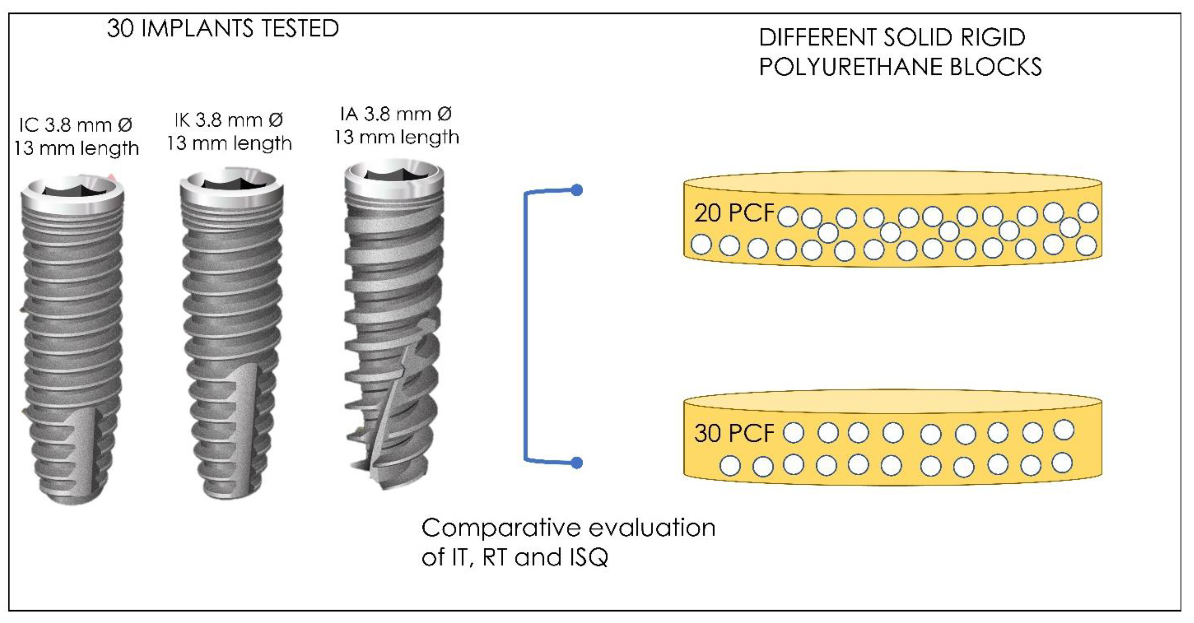
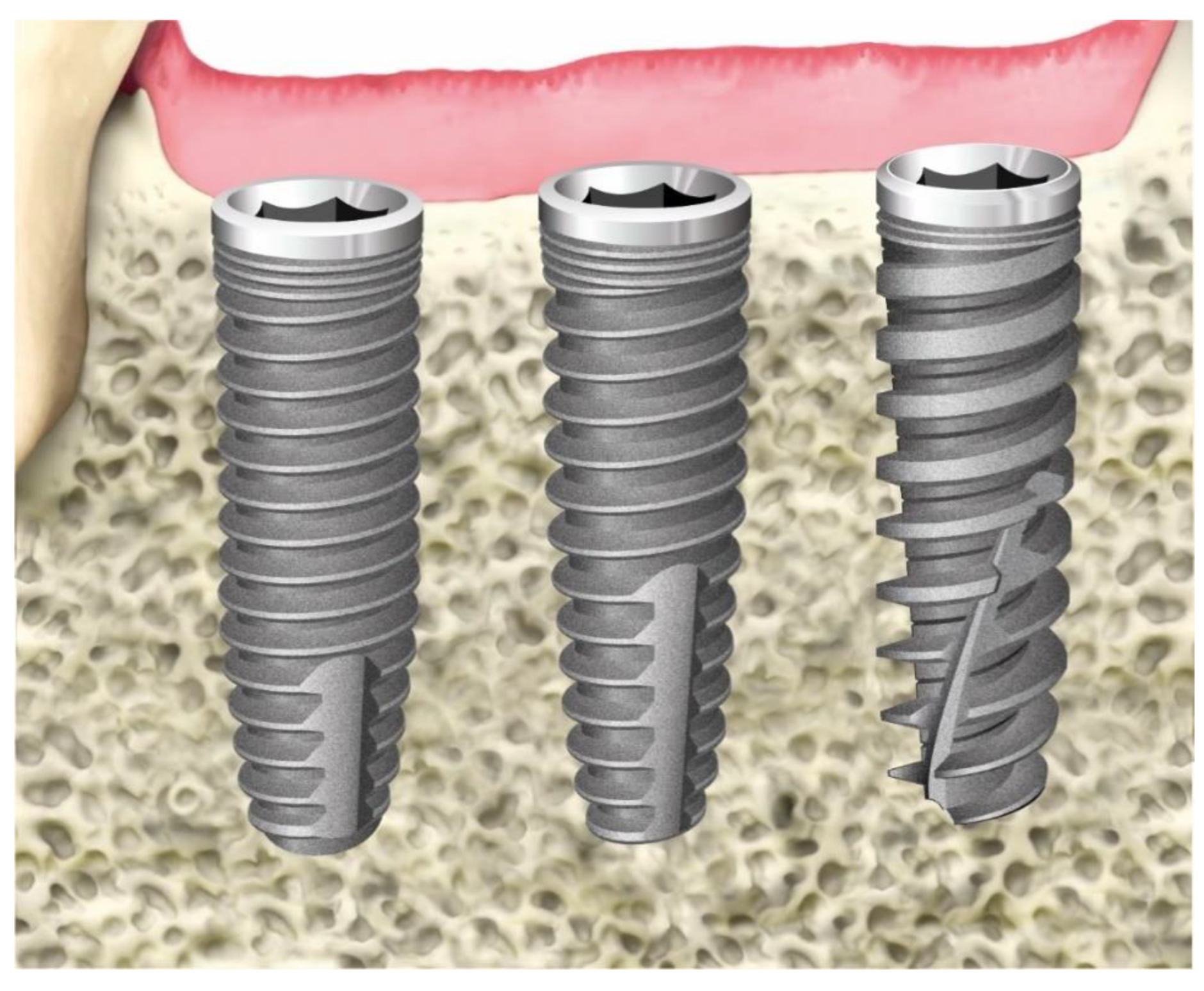
2.1. Implant General Characteristics
- Neck: smooth surface: machined, smoothed, rectify, and protected during the roughening process (neck portion).
- Cylindric: nano-roughened surface: speedy treatment, nano-rough with average Ra less than 1 micron.
- Screw pitch: micro-roughened surface 3/7: double etched (DAE) treatment, micro-rough with average Ra between 3 and 7 µm.
- Tapered: micro-roughened surface 8/12: DAE treatment, micro-rough with average Ra between 8 and 12 micron.
- (a)
- IK (tapered shape) (Resista, Verbania, Italy) are characterized by a smooth implant neck, 3.5 mm high, a rough cylindrical body (DAE differential micromorphology) with a screw pitch of 0.9 mm and a tapered apical portion, 6 mm long. The surface area developed for IK implants is 279.12 mm2.
- (b)
- IC (cylindric shape) (Resista, Verbania, Italy) are characterized by a smooth implant neck 0.5 mm high, a rough cylindrical body (DAE differential micromorphology) with a screw pitch of 0.6 mm and a tapered apical portion, 3 mm long. The surface area developed for IC implants is 271.15 mm2.
- (c)
- IA (active blade conic shape) (Resista, Verbania, Italy) are characterized by a smooth implant neck, 0.5 mm high, a rough cylindrical body (DAE differential micromorphology) with a screw pitch of 1.2 mm and a tapered apical portion 4 mm long. The surface area developed for IA implants is 280.57 mm2.
- (d)
- All of implants tested presented a size of 3.8 diameter and 13 mm length. For each type, a total of 10 implants were used, 5 inserted in the polyurethane block 20 PCF and 5 inserted in the block 30 PCF (SawBones H, Pacific Research Laboratories Inc, Vashon, WA, USA).
2.2. Polyurethane Foam Blocks
2.3. Drilling Protocol
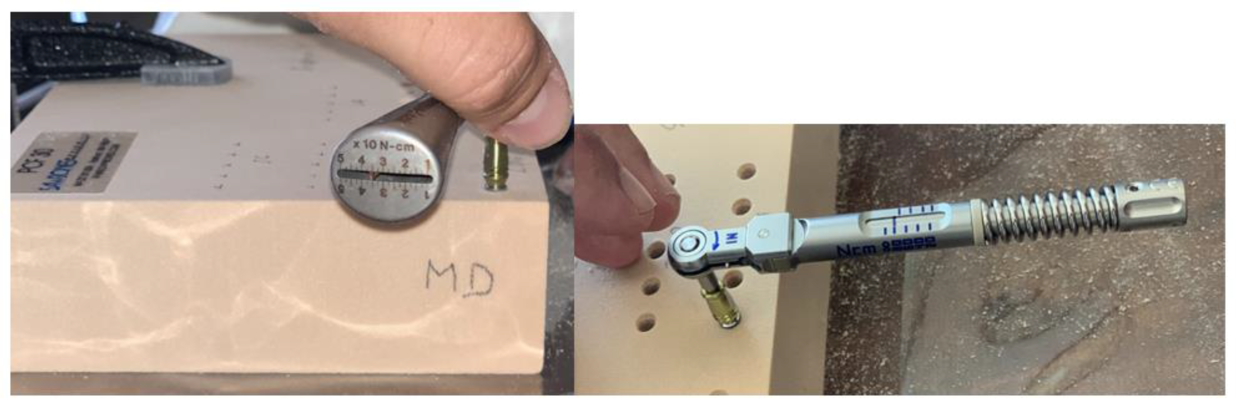
2.4. Primary Stability Measurement
- -
- Mesio-distal
- -
- Vestibulo-lingual
2.5. Statistical Analysis
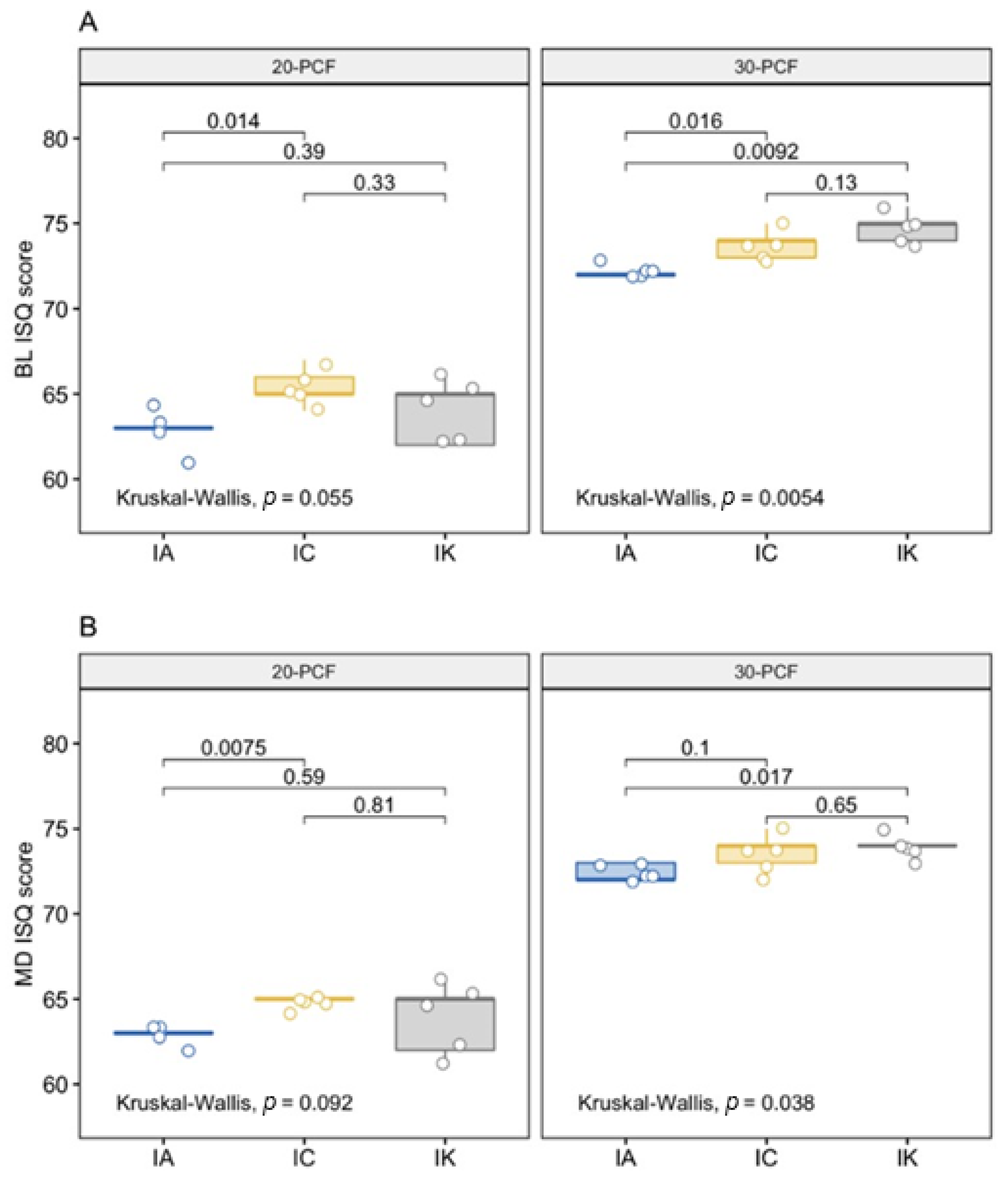
3. Results
4. Discussion
5. Conclusions
Author Contributions
Funding
Institutional Review Board Statement
Informed Consent Statement
Data Availability Statement
Acknowledgments
Conflicts of Interest
References
- Degidi, M.; Piattelli, A.; Gehrke, P.; Felice, P.; Carinci, F. Five-year outcome of 111 immediate nonfunctional single restorations. J. Oral Implantol. 2006, 32, 277–285. [Google Scholar] [CrossRef] [PubMed]
- Scarano, A.; de Oliveira, P.S.; Traini, T.; Lorusso, F. Sinus Membrane Elevation with Heterologous Cortical Lamina: A Randomized Study of a New Surgical Technique for Maxillary Sinus Floor Augmentation without Bone Graft. Materials 2018, 11, 1457. [Google Scholar] [CrossRef] [PubMed]
- Scarano, A.; Murmura, G.; Vantaggiato, G.; Lauritano, D.; Silvestre-Rangil, J.; DI Cerbo, A.; Lorusso, F. Delayed Expansion of Atrophic Mandible (Deam): A Case Report. Oral Implantol. 2017, 10, 190–196. [Google Scholar] [CrossRef]
- Matys, J.; Świder, K.; Flieger, R.; Dominiak, M. Assessment of the Primary Stability of Root Analog Zirconia Implants Designed Using Cone Beam Computed Tomography Software by Means of the Periotest® Device: An Ex Vivo Study. A Preliminary Report. Adv. Clin. Exp. Med. 2017, 26, 803–809. [Google Scholar] [CrossRef] [PubMed]
- Amid, R.; Raoofi, S.; Kadkhodazadeh, M.; Movahhedi, M.R.; Khademi, M. Effect of Microthread Design of Dental Implants on Stress and Strain Patterns: A Three-Dimensional Finite Element Analysis. Biomed. Tech. Biomed. Eng. 2013, 58. [Google Scholar] [CrossRef]
- Udomsawat, C.; Rungsiyakull, P.; Rungsiyakull, C.; Khongkhunthian, P. Comparative Study of Stress Characteristics in Surrounding Bone during Insertion of Dental Implants of Three Different Thread Designs: A Three-Dimensional Dynamic Finite Element Study. Clin. Exp. Dent. Res. 2019, 5, 26–37. [Google Scholar] [CrossRef] [PubMed]
- Tumedei, M.; Piattelli, A.; Degidi, M.; Mangano, C.; Iezzi, G. A Narrative Review of the Histological and Histomorphometrical Evaluation of the Peri-Implant Bone in Loaded and Unloaded Dental Implants. A 30-Year Experience (1988–2018). Int. J. Environ. Res. Public Health 2020, 17, 2088. [Google Scholar] [CrossRef] [PubMed]
- Nedir, R.; Bischof, M.; Szmukler-Moncler, S.; Bernard, J.-P.; Samson, J. Predicting Osseointegration by Means of Implant Primary Stability. A Resonance-Frequency Analysis Study with Delayed and Immediately Loaded ITI SLA Implants. Clin. Oral Implant. Res. 2004, 15, 520–528. [Google Scholar] [CrossRef] [PubMed]
- Isoda, K.; Ayukawa, Y.; Tsukiyama, Y.; Sogo, M.; Matsushita, Y.; Koyano, K. Relationship between the Bone Density Estimated by Cone-Beam Computed Tomography and the Primary Stability of Dental Implants: Relationship between Bone Density and Implant Stability. Clin. Oral Implant. Res. 2012, 23, 832–836. [Google Scholar] [CrossRef]
- Bilhan, H.; Geckili, O.; Mumcu, E.; Bozdag, E.; Sünbüloğlu, E.; Kutay, O. Influence of Surgical Technique, Implant Shape and Diameter on the Primary Stability in Cancellous Bone: What influences primary stability in cancellous bone. J. Oral Rehabil. 2010, 37, 900–907. [Google Scholar] [CrossRef]
- Del Giudice, R.; Piattelli, A.; Grande, N.-M.; Cataneo, E.; Crispino, A.; Petrini, M. Implant Insertion Torque Value in Immediate Loading: A Retrospective Study. Med. Oral Patol. Oral Cir. Bucal 2019, 24, e398–e403. [Google Scholar] [CrossRef] [PubMed]
- Kotsu, M.; Urbizo Velez, J.; Bengazi, F.; Tumedei, M.; Fujiwara, S.; Kato, S.; Botticelli, D. Healing at Implants Installed from ~70- to <10-Ncm Insertion Torques: An Experimental Study in Dogs. Oral Maxillofac. Surg. 2020. [Google Scholar] [CrossRef]
- Javed, F.; Romanos, G.E. The Role of Primary Stability for Successful Immediate Loading of Dental Implants. A Literature Review. J. Dent. 2010, 38, 612–620. [Google Scholar] [CrossRef]
- Hansson, S.; Werke, M. The Implant Thread as a Retention Element in Cortical Bone: The Effect of Thread Size and Thread Profile: A Finite Element Study. J. Biomech. 2003, 36, 1247–1258. [Google Scholar] [CrossRef]
- Misch, C.E.; Strong, I.T.; Bidez, M.W. Implant Design. In Contemporary Implant Dentistry; Mosby Inc.: Mariland Heights, MO, USA, 2007; p. 200. [Google Scholar]
- Misch, C.E. Bone Density: A Key Determinant for Treatment Planning. In Contemporary Implant Dentistry, 3rd ed.; Mosby: St. Louis, MO, USA, 2007; pp. 130–146. [Google Scholar]
- Abuhussein, H.; Pagni, G.; Rebaudi, A.; Wang, H.-L. The Effect of Thread Pattern upon Implant Osseointegration. Clin. Oral Implant. Res. 2010, 21, 129–136. [Google Scholar] [CrossRef] [PubMed]
- Fanali, S.; Tumedei, M.; Pignatelli, P.; Inchingolo, F.; Pennacchietti, P.; Pace, G.; Piattelli, A. Implant Primary Stability with an Osteocondensation Drilling Protocol in Different Density Polyurethane Blocks. Comput. Methods Biomech. Biomed. Eng. 2020, 1–7. [Google Scholar] [CrossRef] [PubMed]
- Comuzzi, L.; Tumedei, M.; Pontes, A.E.; Piattelli, A.; Iezzi, G. Primary Stability of Dental Implants in Low-Density (10 and 20 Pcf) Polyurethane Foam Blocks: Conical vs. Cylindrical Implants. Int. J. Environ. Res. Public Health 2020, 17, 2617. [Google Scholar] [CrossRef] [PubMed]
- Tumedei, M.; Petrini, M.; Cipollina, A.; Di Carmine, M.; Piattelli, A.; Cucurullo, A.; Iezzi, G. Comparative Evaluation of Primary Stability between Different Diameters Multi-Scale Roughness Dental Implant by Solid Rigid Polyurethane Simulation. Osteology 2021, 1, 62–72. [Google Scholar] [CrossRef]
- Staedt, H.; Palarie, V.; Staedt, A.; Wolf, J.M.; Lehmann, K.M.; Ottl, P.; Kämmerer, P.W. Primary Stability of Cylindrical and Conical Dental Implants in Relation to Insertion Torque-A Comparative Ex Vivo Evaluation. Implant. Dent. 2017, 26, 250–255. [Google Scholar] [CrossRef]
- Menicucci, G.; Pachie, E.; Lorenzetti, M.; Migliaretti, G.; Carossa, S. Comparison of Primary Stability of Straight-Walled and Tapered Implants Using an Insertion Torque Device. Int. J. Prosthodont. 2012, 25, 465–471. [Google Scholar]
- Atieh, M.A.; Alsabeeha, N.; Duncan, W.J. Stability of Tapered and Parallel-Walled Dental Implants: A Systematic Review and Meta-Analysis. Clin. Implant. Dent. Relat. Res. 2018, 20, 634–645. [Google Scholar] [CrossRef]
- Meirelles, L.; Currie, F.; Jacobsson, M.; Albrektsson, T.; Wennerberg, A. The Effect of Chemical and Nanotopographical Modifications on the Early Stages of Osseointegration. Int. J. Oral Maxillofac. Implant. 2008, 23, 641–647. [Google Scholar]
- Alves, C.C.; Neves, M. Tapered Implants: From Indications to Advantages. Int. J. Periodontics Restor. Dent. 2009, 29, 161–167. [Google Scholar]
- Roberts, W.E.; Smith, R.K.; Zilberman, Y.; Mozsary, P.G.; Smith, R.S. Osseous Adaptation to Continuous Loading of Rigid Endosseous Implants. Am. J. Orthod. 1984, 86, 95–111. [Google Scholar] [CrossRef]
- Ma, P.; Xiong, W.; Tan, B.; Geng, W.; Liu, J.; Li, W.; Li, D. Influence of Thread Pitch, Helix Angle, and Compactness on Micromotion of Immediately Loaded Implants in Three Types of Bone Quality: A Three-Dimensional Finite Element Analysis. BioMed Res. Int. 2014, 2014, 983103. [Google Scholar] [CrossRef] [PubMed]
- Ryu, H.-S.; Namgung, C.; Lee, J.-H.; Lim, Y.-J. The Influence of Thread Geometry on Implant Osseointegration under Immediate Loading: A Literature Review. J. Adv. Prosthodont. 2014, 6, 547–554. [Google Scholar] [CrossRef]
- Chang, P.-K.; Chen, Y.-C.; Huang, C.-C.; Lu, W.-H.; Chen, Y.-C.; Tsai, H.-H. Distribution of Micromotion in Implants and Alveolar Bone with Different Thread Profiles in Immediate Loading: A Finite Element Study. Int. J. Oral Maxillofac. Implant. 2012, 27, e96–e101. [Google Scholar]
- Lan, T.-H.; Du, J.-K.; Pan, C.-Y.; Lee, H.-E.; Chung, W.-H. Biomechanical Analysis of Alveolar Bone Stress around Implants with Different Thread Designs and Pitches in the Mandibular Molar Area. Clin. Oral Investig. 2012, 16, 363–369. [Google Scholar] [CrossRef]
- Hansson, S. The Implant Neck: Smooth or Provided with Retention Elements. A Biomechanical Approach. Clin. Oral Implant. Res. 1999, 10, 394–405. [Google Scholar] [CrossRef]
- Koodaryan, R.; Hafezeqoran, A. Evaluation of Implant Collar Surfaces for Marginal Bone Loss: A Systematic Review and Meta-Analysis. BioMed Res. Int. 2016, 2016, 4987526. [Google Scholar] [CrossRef]
- Calvo-Guirado, J.L.; Jiménez-Soto, R.; Pérez Albacete-Martínez, C.; Fernández-Domínguez, M.; Gehrke, S.A.; Maté-Sánchez de Val, J.E. Influence of Implant Neck Design on Peri-Implant Tissue Dimensions: A Comparative Study in Dogs. Materials 2018, 11, 2007. [Google Scholar] [CrossRef] [PubMed]
- Spies, B.C.; Bateli, M.; Ben Rahal, G.; Christmann, M.; Vach, K.; Kohal, R.-J. Does Oral Implant Design Affect Marginal Bone Loss? Results of a Parallel-Group Randomized Controlled Equivalence Trial. BioMed Res. Int. 2018, 2018. [Google Scholar] [CrossRef]
- Dreyer, H.; Grischke, J.; Tiede, C.; Eberhard, J.; Schweitzer, A.; Toikkanen, S.E.; Glöckner, S.; Krause, G.; Stiesch, M. Epidemiology and Risk Factors of Peri-Implantitis: A Systematic Review. J. Periodontal Res. 2018, 53, 657–681. [Google Scholar] [CrossRef] [PubMed]
- Schimmel, M.; Srinivasan, M.; McKenna, G.; Müller, F. Effect of Advanced Age and/or Systemic Medical Conditions on Dental Implant Survival: A Systematic Review and Meta-Analysis. Clin. Oral Implant. Res. 2018, 29, 311–330. [Google Scholar] [CrossRef] [PubMed]
- Ding, X.; Liao, S.-H.; Zhu, X.-H.; Zhang, X.-H.; Zhang, L. Effect of Diameter and Length on Stress Distribution of the Alveolar Crest around Immediate Loading Implants. Clin. Implant. Dent. Relat. Res. 2009, 11, 279–287. [Google Scholar] [CrossRef]


| Implant Stability | 20-PCF | 30-PCF | p-Value | ||||
|---|---|---|---|---|---|---|---|
| IA | IC | IK | IA | IC | IK | ||
| n | 5 | 5 | 5 | 5 | 5 | 5 | |
| BL (mean (SD)) | 62.80 (1.10) | 65.40 (1.14) | 64.00 (1.87) | 72.20 (0.45) | 73.80 (0.84) | 74.80 (0.84) | <0.001 |
| MD (mean (SD)) | 62.80 (0.45) | 64.80 (0.45) | 63.80 (2.17) | 72.40 (0.55) | 73.60 (1.14) | 74.00 (0.71) | <0.001 |
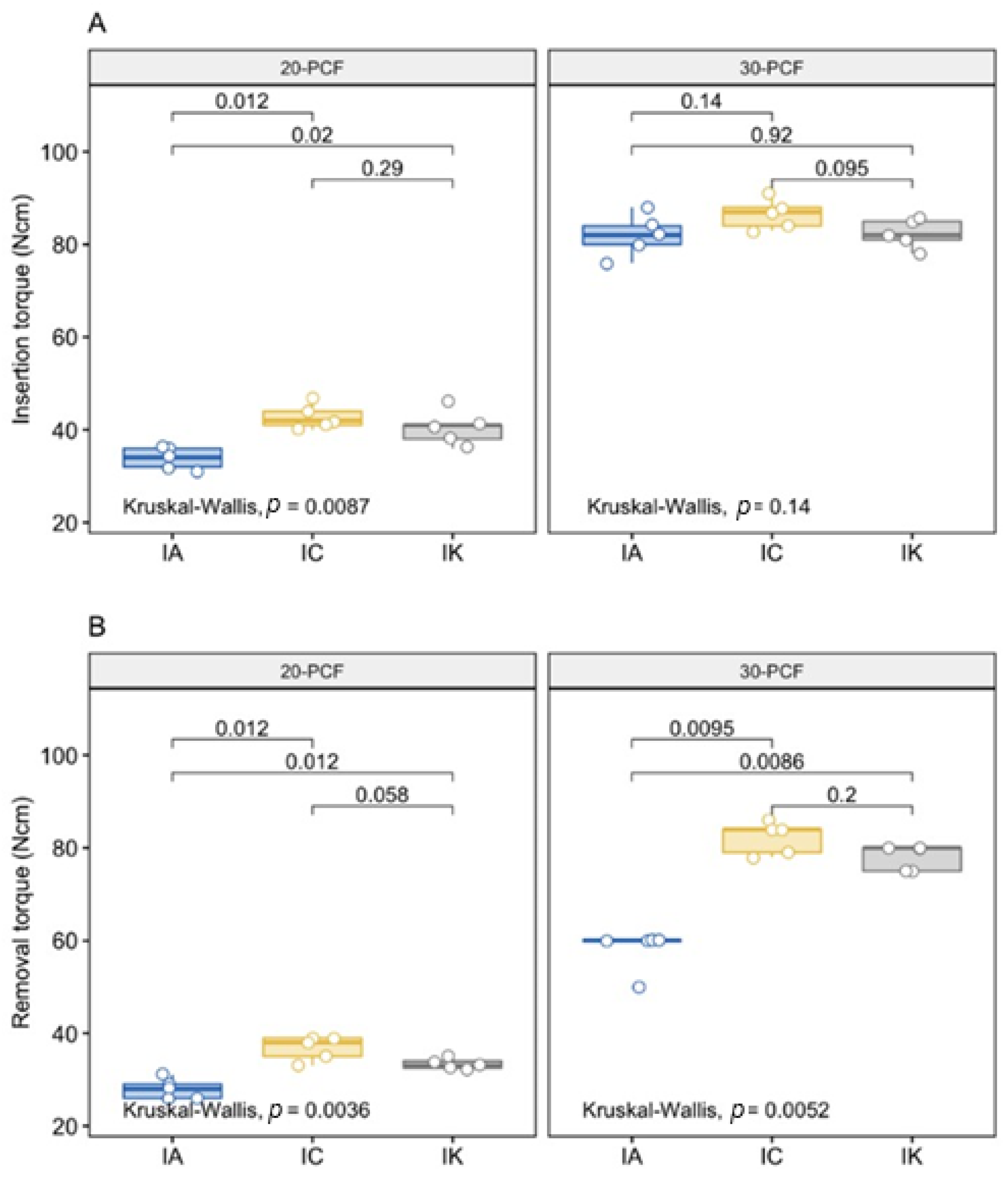
| IT (mean (SD)) | 33.80 (2.28) | 42.80 (2.77) | 40.40 (3.78) | 82.00 (4.47) | 86.60 (3.21) | 82.40 (3.21) | <0.001 |
| RT (mean (SD)) | 28.00 (2.12) | 36.80 (2.68) | 33.30 (1.20) | 58.00 (4.47) | 82.20 (3.49) | 78.00 (2.74) | <0.001 |
Publisher’s Note: MDPI stays neutral with regard to jurisdictional claims in published maps and institutional affiliations. |
© 2021 by the authors. Licensee MDPI, Basel, Switzerland. This article is an open access article distributed under the terms and conditions of the Creative Commons Attribution (CC BY) license (https://creativecommons.org/licenses/by/4.0/).
Share and Cite
Tumedei, M.; Petrini, M.; Pietropaoli, D.; Cipollina, A.; La Torre, C.; Di Carmine, M.S.; Piattelli, A.; Iezzi, G. The Influence of the Implant Macrogeometry on Insertion Torque, Removal Torque, and Periotest Implant Primary Stability: A Mechanical Simulation on High-Density Artificial Bone. Symmetry 2021, 13, 776. https://doi.org/10.3390/sym13050776
Tumedei M, Petrini M, Pietropaoli D, Cipollina A, La Torre C, Di Carmine MS, Piattelli A, Iezzi G. The Influence of the Implant Macrogeometry on Insertion Torque, Removal Torque, and Periotest Implant Primary Stability: A Mechanical Simulation on High-Density Artificial Bone. Symmetry. 2021; 13(5):776. https://doi.org/10.3390/sym13050776
Chicago/Turabian StyleTumedei, Margherita, Morena Petrini, Davide Pietropaoli, Alessandro Cipollina, Castrenze La Torre, Maria Stella Di Carmine, Adriano Piattelli, and Giovanna Iezzi. 2021. "The Influence of the Implant Macrogeometry on Insertion Torque, Removal Torque, and Periotest Implant Primary Stability: A Mechanical Simulation on High-Density Artificial Bone" Symmetry 13, no. 5: 776. https://doi.org/10.3390/sym13050776
APA StyleTumedei, M., Petrini, M., Pietropaoli, D., Cipollina, A., La Torre, C., Di Carmine, M. S., Piattelli, A., & Iezzi, G. (2021). The Influence of the Implant Macrogeometry on Insertion Torque, Removal Torque, and Periotest Implant Primary Stability: A Mechanical Simulation on High-Density Artificial Bone. Symmetry, 13(5), 776. https://doi.org/10.3390/sym13050776