Article

Energy Saving and Economic Evaluations of Exhaust Waste Heat Recovery Hot Water Supply System for Resort

1
Faculty of Mechanical Engineering, Nha Trang University, 02 Nguyen Dinh Chieu Street, Nha Trang City 650000, Vietnam
2
Department of Robotics and Intelligent Machine, Yeungnam University, 280 Daehak-ro, Gyeongsan 38541, Korea
3
Department of Mechanical Engineering, Dong-A University, 37 Nakdong-daero 550, Saha-gu, Busan 49315, Korea
*
Author to whom correspondence should be addressed.
These authors contributed equally to this work.
Symmetry 2021, 13(4), 624; https://doi.org/10.3390/sym13040624
Submission received: 22 March 2021 / Revised: 5 April 2021 / Accepted: 7 April 2021 / Published: 8 April 2021
(This article belongs to the Special Issue Heat Transfer in Engineering)

Abstract

:
The objective of this study is to investigate the energy savings and economics of the hot water supply system for the luxury resort. The hot water was generated using the waste heat from the exhaust gas heat (EGH) of internal combustion engine (ICE) installed at the luxury resort. The capacity and characteristics of waste heat source, flow demand and supply system of hot water were surveyed, and data is collected from the real system. The new heat exchanger system which utilizes the EGH to produce the hot water is designed considering the dew point temperature and the back pressure of exhaust gas system. The results show that the proposed system could supply hot water at a temperature of 55 °C corresponding to the present resort demand of 6 m3/h using EGH of ICE at 20% load. The proposed system could achieve the saving of 400 L/day in diesel oil (DO) fuel consumption and the payback time of new system could be evaluated as 9 months. The proposed system could produce hot water of 14 m3/h at 25% of engine load and 29 m3/h at full engine load which are sufficient to satisfy the regular and maximum hot water demand of resort. The presented results show the capability of the proposed system to satisfy the current hot water demand of resort and suggest the larger potential to save energy by recovering EGH of ICE. The novelty of the present work involves detailed methodology to design heat exchangers and evaluate system economics for hot water supply system based on EGH of ICE.

1. Introduction

In the present time, energy saving methods and techniques in various industries are very important to prevent the global energy crisis, increasing fuel consumption and oil price and decrease the fossil fuel energy use [1]. Especially, the uses of the fossil fuels have caused the ozone layer depletion and the ecological problems including the global warming and air pollution. There are two ways to overcome these international issues. One is the replacement of the old systems with low operation efficiency for the purpose of decreasing the lost energy. Another is the re-use of the waste energy from the present systems for the purpose of improving the efficiency. To reuse a part of energy exhausted to the environment after system operation as a waste heat is a general method [2]. There is lot of research interest in utilizing waste heat to satisfy the energy demand. To utilize the waste heat effectively, the attention needs to be given to the characteristics of waste heat source and the characteristics of used place. The attention aspects are type, chemical components and basic parameters (pressure, temperature and flow), stability and continuity of waste heat source, purpose and size of application, technology and waste heat recovery system diagram and economic efficiency. The waste heat source could be utilized by the direct and indirect way. If the waste heat source is clean and no-corrosive, then could be used directly otherwise indirectly through the intermediate heat exchanger. Based on the types and the physical properties of the waste heat source, the type of heat exchanger is selected. If the waste heat source is flue gas from ICE or gas turbine then the exhaust gas-to-steam heat exchanger or exhaust gas-to-hot water heat exchanger could be used [3]. If the WH source is liquid then depend on the liquid temperature, the liquid-to-steam heat exchanger or the liquid-to-hot water heat exchanger could be selected.
There are now many services as motels, hotels and resorts which were built for the purpose of travel and lodging. The tourists usually enjoy coming to the quiet places with clean environment to relax. Therefore, many resorts were built in farther places from the urban, near to the coastline or on the islands. Due to the geographic location, many resorts cannot connect with the power grid, so that the ICE for electric generation is usually chosen. Beside the power demands, hot water and steam are the important issues.
Many previous studies have focused on the waste heat recovery from the ICE to enhance the performance. The general technologies and waste heat sources of combined heat and power systems were presented in [4,5,6] and typical recovery of EGH from ICE were introduced in [7,8,9]. Separate Rankine cycle could provide additional power of 12–16% from the waste heat of diesel engine [10,11]. The recovering of waste heat of ICE stored about 10–15% of fuel power in storage system [12,13]. The waste heat recovery from ICE of vehicle was investigated by combined thermodynamic cycles and shown good effective energy savings [14,15,16,17]. The cooling capacity of absorption refrigeration system was improved by using the exhaust gas of ICE [18,19]. The exhaust gas recovery using various bottom cycles showed improvement in the engine thermal efficiency [20,21]. The Rankine steam cycle presented the maximum energy saving potentials [22,23]. Generally, depend on the load of ICE and the applied cycle, the effective energy up to 10–20% could be achieved by recovering the waste heat from ICE. Many research show that a huge amount of energy is lost in form of heat through the exhaust gas which is about 30–40% of the combustion heat [12,13,23,24]. The generated exhaust gases are about 50–70% of the fuel input and waste heat from exhaust gas could be recovered through the engine cooling [25]. Majority of the research studies are focused on the additional power for the engine by utilizing the waste heat of ICE [10,11,14,15], some of research studies were applied in cooling [18,19] and some research was focused on the residential applications [4,9,26]. However, there are only few research studies which presented the application of waste heat in residential and small commercial buildings [4,9]. Onovwiona et al. presented the assumed data and simulated results of waste heat recovery system of ICE [26]. Jia et al. have proposed novel gas-engine driven heat pump system to overcome the limitation of insufficient engine exhaust waste heat for hot water supply [27]. Liu et al. have presented the exhaust waste heat recovery system for hot water supply which comprises of solar energy collection system, drainage system and heat pump system [28]. Butrymowicz et al. have conducted experimental study on the waste heat recovery system which uses waste heat of combustion engines for heating applications [29]. Kunal et al. have investigated the utilization of waste heat of ICE for thermoelectric power generation [30,31]. Estefania et al. have developed the energy recovery-based heat pump system which uses low grade temperature source for domestic hot water supply [32]. Ahmadi et al. have proposed solar thermal energy based parallel feed water heating system for power plant units. The net energy and exergy efficiencies of the proposed system are increased by 9.5% by using solar collectors as the replacement of high-pressure feed water heaters [33]. Ahmadi et al. have also simulated the energy and exergy performances of feed water heating repowering for steam power plan under three operating modes [34]. The repowering of steam power plant with and without integration of solar energy has been investigated based on energy, energy and environmental aspects [35].
The conducted literature review reveals that there has been no study reported until now which uses the exhaust gas of ICE for the purpose of the hot water supply as an application of waste heat recovery. Therefore, this study focuses on the energy savings and economic evaluations of proposed hot water supply system which recovered the EGH from the ICE to produce hot water for resort. The recovered EGH from ICE is used to heat the water though the heat exchanger system. This will decrease the steam for heating water and reduces the oil consumption of the boiler for the existing system. The daily demand and volume flow rate of hot water at peak hour are surveyed. The fuel consumption and exhaust gas of ICE are investigated. The new heat exchanger system to recover EGH to hot water is proposed. The dew point temperature and the back pressure of exhaust gas are considered in design. The investment cost is calculated to evaluate the payback time of the proposed system. The findings clarify the effectiveness of utilizing exhaust gas heat of ICE to produce hot water, and simultaneously provide scientific data for constructing a new heat recovery system. The detailed methodology for designing the waste heat recovery heat exchanger is presented which could be reference guideline for the active researcher in the field of waste heat recovery application which is not cover in relevant articles in the open literature. In addition, the methodology for evaluating the economics of the waste recovery system is presented explicitly.

2. Methodology

2.1. Description of Engine and Hot Water Demand

The investigated luxury resort is located at the island which is a popular tourist place. It has the hotels and restaurants with five stars standard and a nice quiet beach. There are many travelers from all over the world are coming here. Beside the tourist demands, this place is used for organizing the national and international events. This resort has 300 high level rooms for 400–500 visitors at the present time, about 80–90% of the rooms are occupied daily and 100% in the holidays. It has 3 restaurants with about 1000 seats and has 01 canteen for about 200 staffs. This resort is on offshore islands, farther from the land, and the main transportation is by the ship, the electric power was generated by ICE combined with generator. The demand for hot water and steam are quite high, hot water is used mainly for bathing and steam is used for hot water heating and laundry. At the present, the hot water is supplied by the heat of boiler using DO fuel. So, if we utilize the waste heat from EGH of the ICE to replace a part or fully the steam from the boiler, the cost of fuel consumption will be decreased. The average exhaust gas temperature of ICE is about 400–500 °C. Current temperature is not enough for the engine cycle, but very suitable for another heat process. The specifications of ICE were investigated in this study as shown in Table 1. It has a close cooling system by an inside solution and outside by air cooling, so we cannot utilize this waste heat source. Thus, we only can utilize waste heat source from exhaust gas of this ICE. The used fuel of ICE is DO, the fuel consumption and exhaust gas temperature changed according to the ICE load as shown in Table 2. It is obvious that the DO fuel consumption increases as the engine load increases which results into increase in the exhaust gas temperature. This is because increase in the heat carrying capacity of exhaust gas with increase in the DO fuel consumption. The data presented in Table 2 show that the waste heat percentage is more at the higher engine load. So, increasing hot water demand at the resort could be satisfied by running the engine at the higher loads.
At the resort, the requirement of hot water temperature is ensured in range of 50–55 °C. The real data of daily hot water volume for 7 months including summer months (July and August), Christmas and new year (December and January) was collected. Figure 1 presents the daily hot water consumption volume of four months higher number of tourists. It can be observed that the hot water volume changed daily, monthly, and average demand is about 50–55 m3/day. The hot water demand changes due to fluctuation in the number of tourists on daily and monthly basis. However, there are some peak days with the hot water volume increases to 80–90 m3/day. From these collected results, the volume flow rate and its ratio with maximum hot water volume flow rate per day were determined, as shown in Table 3. The hot water demand of resort for three volumes namely, maximum, minimum and average is evaluated from the collected data of real system. Considering the average hot water demand as the baseline, the maximum and minimum hot water demands are 180% higher and 42% lower, respectively.

2.2. Description of Proposed System

The system diagram of proposed hot water supply system based on hot water demand and EGH recovery from ICE to produce hot water was proposed is shown in Figure 2. The EGH of ICE is not directly used to produce the hot water for resort in order to restrain the scale inside the tube exchanger. The EGH of ICE is exchanged with intermediate heat source (primary hot water), thus this system has two hot water circles. In the primary circle (closed circle), the fresh water is pumped into the primary heat exchanger and is heated by hot exhaust gas from ICE. This hot water becomes the heat source for the secondary circle. In the secondary circle (opened circle), the water is heated by primary hot water to temperature of 55 °C, then is pumped to the hot water system of the hotel and distributed to all rooms. The part of hot water with decreased temperature which is not used will be returned to the heat exchanger and reheated again. The make-up water is pumped to the system to compensate the part of used hot water.

3. Design of Proposed System

3.1. Specifications of Exhaust Gas

The load of ICE changed from 70 to 90% at the current time in a day, so the load of ICE at 80% is chosen for the heat exchanger design and correspondingly the exhaust gas temperature is teg in1 = 470 °C. From the technical specifications of ICE, the mass flow rate of exhaust gas Geg = 6000 kg/h. From the physical specifications of the used DO fuel, the sulfur concentration is S = 0.445%. From the graph of flue gas dew point temperature [36], the dew point temperature of exhaust gas is tdp = 110 °C. The reaction SO3 + H2O = H2SO4 in exhaust gas system which causes the corrosion in chimmy or on the surface of the heat exchanger at low ICE load is prevented. We choose the minimum exhaust gas temperature teg out1 = 130 °C. Thus, the total heat recovery from EGH of ICE can be determined:
Q e g = G e g · c p e g ( t e g   i n 1 t e g   o u t 1 )
where cpeg is the average specific heat of exhaust gas (cpeg = 1.174 kJ/kg °C). Thus, from Equation (1) Qeg = 665 (kW).

3.2. Calculation of Volume Flow Rate of Hot Water

The hot water volume is always changed according to the demand. Therefore, the maximum volume flow rate of hot water per hour (Vhwmax/h) needs to be defined. Based on the make-up water volume into the system, the Vhwmax/h was collected for typical 10 days of the month with higher number of tourists as shown in the Figure 3. As can be seen, there is a time when Vhwmax/h is ranging from 16–20 pm daily. From these data, the ratio of average hot water volume flow rate per hour with its value per day was calculated as shown in the Figure 4. It can be observed that the ratio of Vhwmax/h at peak hour is nearly 6% from daily hot water volume which is suggested for other days in the year. Thus, from the maximum hot water volume as suggested in Table 3, Vhwmax/d = 94 m3/day and the above ratio of 6% at peak hour, the Vhwmax/h was determined such that Vhwmax/h = 94 × 6/100 = 5.65 m3/h.

3.3. Maximum Production of Hot Water Volume

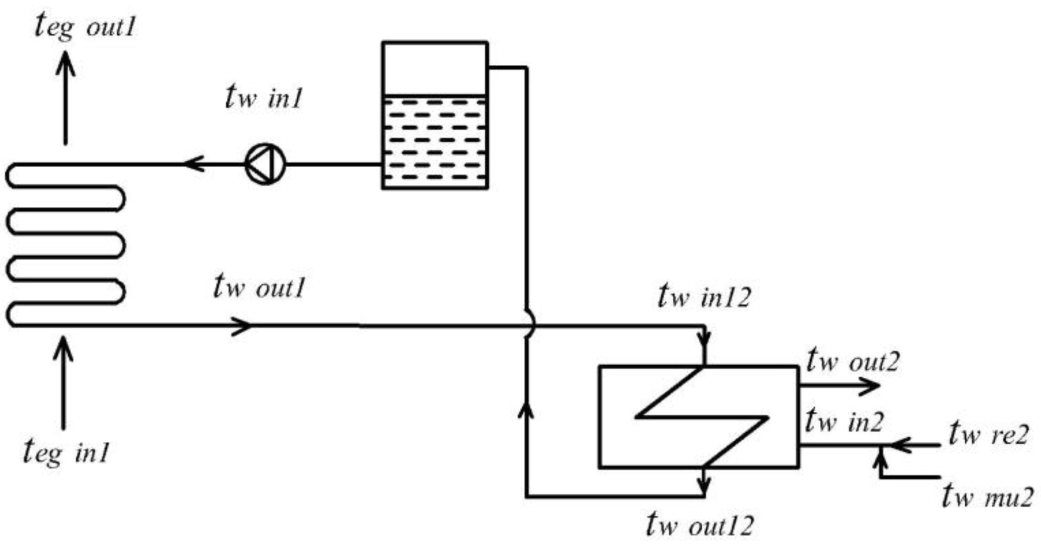
Figure 5 shows the diagram of separate hot water system. To ensure the continuous and adequate hot water supply, the hot water is always revolved in the system with the circulating hot water flow (Vcc) and requirement is Vcc > Vhwmax/h. The circle factor (n) is introduced, with n = V c c V h w a , we choose n = 2.75 in this study. From 
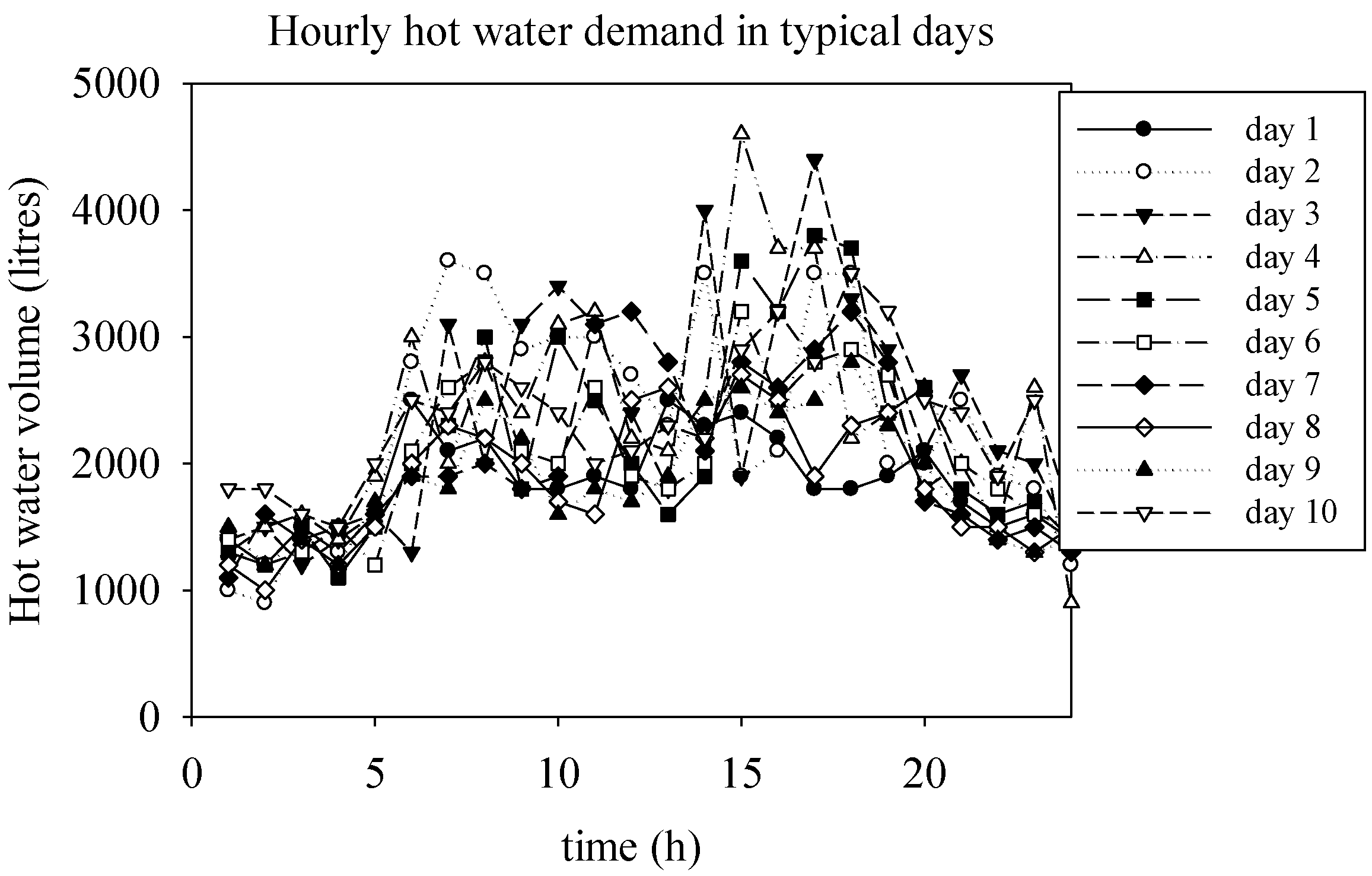
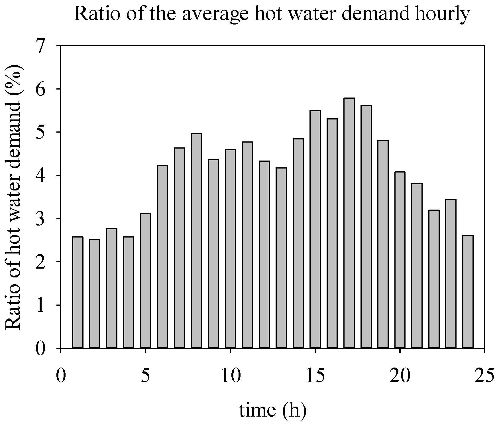
Table 3, the average hot water demand is Vhwa = 52 m3/day = 2.2 m3/h, the circular water flow can be defined Vcc = Vhwa × n = 6 m3/h > Vhwmax/h = 5.65 m3/h, that means the supplied hot water demand at peak hour will be ensured. From there, the volume flow rate of make-up water (Vmu) to the system is calculated, Vmu = Vhwa = VccVre, where Vre is the returned hot water flow rate. The temperature of returned hot water (tre) is decreased because of occurred heat loss along the length of tube, this range temperature is set Δt = 15 °C. Thus, the tre = 55 − 15 = 40 °C. The heat balance equation is established at the entrance of secondary heat exchanger:
V r e · C p w ( t w   r e t w   i n 2 ) = C p w ( t w   i n 2 t w   m u )
where, Cpw is the specific heat of water, the water-in temperature of secondary heat exchanger (tw in2), tw mu is the temperature of make-up water (tmu = 25 °C at the investigated resort). Thus, from Equation (2) tw in2 = 35 °C.
The heat transfer rate from the exhaust gas to the water is presented by the balance equation:
η · Q e g = Q h w = V h w · C p w ( t w   o u t 2 t w   i n 2 )
where Qhw is the heat rate of water, Vhw is the maximum volume flow rate of hot water that could be produced, Cpw is the water specific heat (Cpw = 4.18 kJ/kg °C), η is the performance of the heat exchanger (η = 0.9).
Thus, from Equation (3) the maximum volume flow rate of hot water from the fully exhaust gas is evaluated as Vhw = 26 m3/h at 80% load of ICE. This flow rate is larger than the flow rate of the circular hot water (Vcc = 6 m3/h), it means that the EGH from ICE responses sufficiently to the demand of hot water at the resort.

3.4. Specifications of Heat Exchanger

The specifications of two heat exchangers were designed and chosen from the parameters of exhaust gas and hot water. Firstly, the tube diameter, tube spacing, the heat transfer coefficient (k1), the length (L1) and the width (W1) are selected for the primary heat exchanger unit. Next, the area of heat exchanger (F1), number of tube rows, number of tubes are calculated followed by calculation of the resistance. If the back pressure or resistance (Δp1) is larger than the allowed back pressure ([Δp1]) then L1 and W1 are re-adjusted. The steps are repeated and the k1 is re-tested. The specifications for which the Δp1 is lower than [Δp1] = 3000 Pa are accepted.
Calculate the resistance though the heat exchanger:
The parameters of the tube and fin such as the outside diameter of the tube (dout1), horizontal spacing (s1), fin spacing (sf) and fin thickness (δf) were selected. The vertical spacing (s2) is evaluated as s 2 = 3 2 s 1 , the slit between two fins (tf) is calculated as t f = s f δ f , the diameter of the fin (df) is calculated as d f = s 1 t f , the height of the fin (hf) is calculated as h f = 0.5   ( d f d o u t 1 ) , number of the fin per 1 m length of tube (nf) is evaluated as n f = 1 s f .
The factor of the fin (CT [1]/136):
ε f = 1 + d f 2 d o u t 1 2 2 × d i n 1 × s f
The area without fin per 1 m length of tube (m2):
F 0 = π × d o u t 1 × t f × n f
The area with fin per 1 m length of tube (m2):
F f = π 2 ( d f 2 d o u t 1 2 ) n f
Total the outside area of fin-tube: F2 = F0 + Fc.
The equivalent diameter of the slits between tubes and fins through which gas flow passes (CT [1]/118):
d e q i = F 0 d o u t 1 + F f F f 2 n f F 0 + F f
The hot water flow rate needs to be produced (Vhw) is known based on the hot water demand. Based on the heat balance equation of secondary heater, the primary hot water flow (Vhw1) is calculated as:
V h w 1 c p w 1 ( t h w   o u t 1 t h w   i n 1 ) η = V h w 2 c p w 2 ( t h w   o u t 2 t h w   i n 2 )
Based on the heat balance equation of primary heater, the exhaust gas-out temperature (tkr) is calculated as:
G e g c p e g ( t e g   i n 1 t e g   o u t 1 ) η =   V h w 1 c p w 1 ( t h w   o u t 1 t h w   i n 1 )
The heat transfer coefficient (kF2) was selected in the suitable range of kF2 = 40–80 W/m2·K based on common design.
Calculate the average temperature difference ( Δ t ¯ ) with Δtmax = tegin1thw out1 and Δtmin = tegout1thw in1:
Δ t ¯ = Δ t m a x Δ t m i n ln Δ t m a x Δ t m i n
Calculate the heat power required to heat the hot water at rate flow demand (Qhwd):
Q h w d = G e g c p e g ( t e g   i n 1 t e g   o u t 1 )
Calculate the waste heat power:
Q e g = G e g c p e g ( t e g   i n 1 t a i r )
Calculate the waste heat recovery efficiency:
η H R = Q h w d Q e g × 100   ( % )
Calculate the inside (F1) and outside area (F2) of fin-tube:
F 2 = Q h w d k F 2 Δ t ¯   and   F 1 = F 2 ε f
The total length of the heat transfer tube was calculated:
F 1 = F 1 π d i n 1
The length of 1 tube (L1) was as the width of the heat exchanger as W1 = L1. Numbers of rows of tube (z1), number of tubes in 1 row (m1), the height of the heat exchanger (H1) were evaluated as, z1 = W1/s2, m 1 = l 1 z 1 L 1 , H1 = m1·s1.
The velocity of exhaust gas flow through minimum cross section was defined (CT [1]/121):
ω = ω 0 1 ( d o u t 1 s 1 + 2 h ω f s 1 s f )
where ω 0 is the velocity of exhaust gas-in, ω 0 = G e g ρ f and f is the area of cross section, f = L × W.
From the average temperature exhaust gas (tk) and t e g = t e g   i n 1 t e g   o u t 1 2 , the heat conductive coefficient (λ) and the viscosity (v) of exhaust gas were known.
The number Re of exhaust gas was calculated:
Re e g = ω d e q i υ
The resistance factor (ξ) for the staggered arrangement tubes with circle fins was defined (CT [1]/119):
ξ = 0.72 × Re e g 0.245 ( s 1 d o u t 1 s f + 2 ) 0.9 × ( s 1 d o u t 1 d o u t 1 ) 0.9 × ( d e q i d o u t 1 ) 0.9 × ( s 1 d o u t 1 s 2 d o u t 1 ) 0.1
The resistance of friction (Δpf), the local resistance at inlet and outlet (Δpl), the total resistance of the system (Δp) were calculated, Δp1 = Δpf + Δpl:
Δ p f = ξ × ρ × ω 2 2 × z 1
Δ p l = ξ × ρ × ω 2 2
The total resistance of the system (Δp) has to be lower than the allowable resistance in the exhaust gas system of ICE [Δ
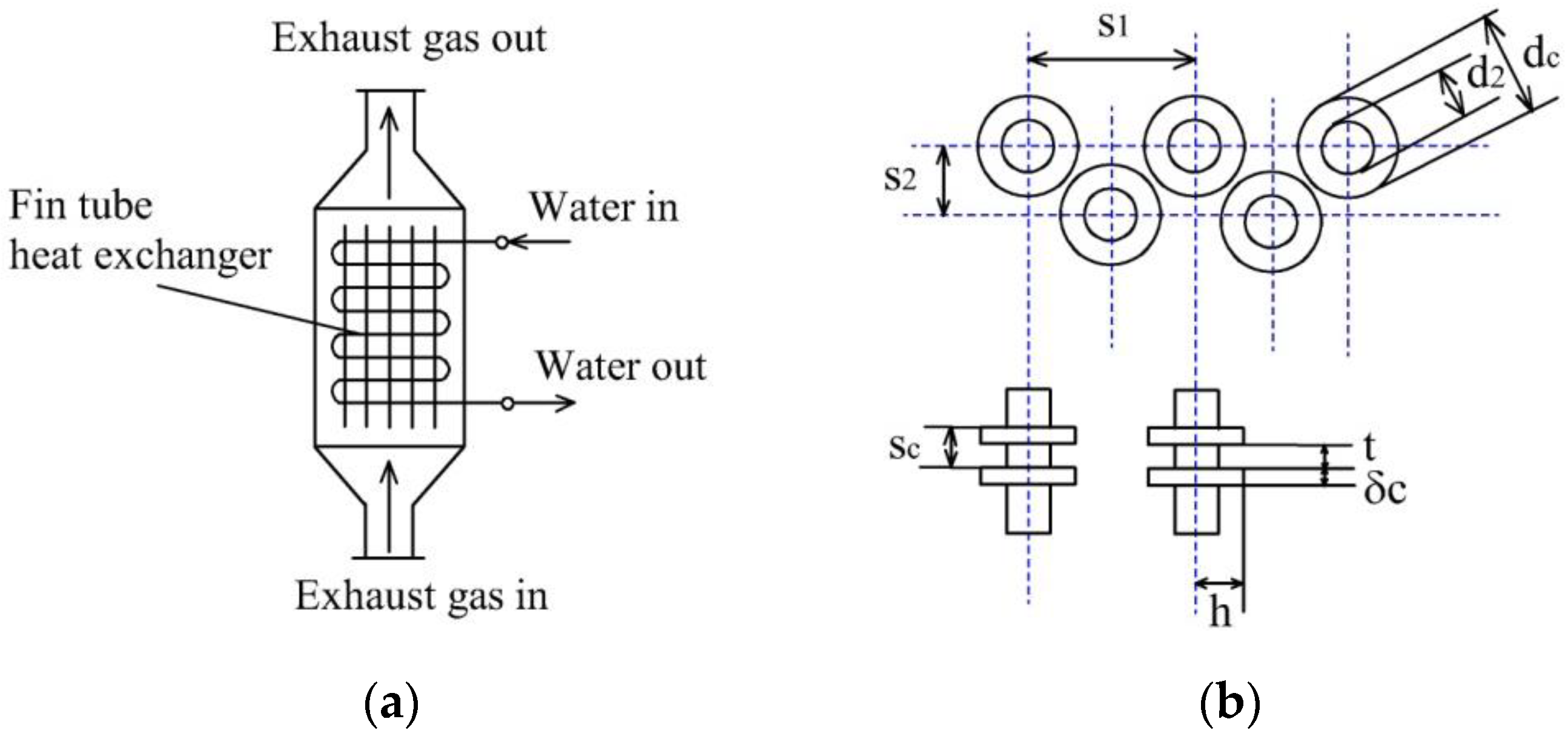
p] = 3000 Pa. Using the design procedure explained above, the specifications of primary and secondary heat exchangers are evaluated. The type of heat exchanger selected for primary case is tube and fin type heat exchanger. The water to be heated is flowing through tubes whereas the exhaust gas is flowing around the tubes. The flow paths for water and exhaust gas are presented in Figure 6a. The tube and fins in the primary heat exchanger are made up of steel. The inner and outer diameters of tube are 27.24 mm and 34 mm, respectively and total length of tube is 4.4 m with spacing of 7 mm. The fin thickness and spacing are designed as 1 mm and 4 mm, respectively. The arrangement and dimensions of fins are depicted in Figure 6b. The summary for specifications of primary heat exchanger is shown in Table 4. Similarly, the type of heat exchanger, the heat transfer coefficient (k2), the area of heat exchanger (F2), number of tube rows, number of tubes and the resistance are calculated for the secondary heat exchanger unit. The shell and tube heat exchanger are selected for secondary circle. The water heated through the exhaust gas is passing through the shell whereas, the fresh water is circulating through the tubes. The flow patterns for both water paths are shown in Figure 7. The secondary heat exchanger comprises of 3 shell passes and 36 tubes divided equally in 3 tube passes. The outer diameter and length of tube are evaluated as 19 mm and 740 mm, respectively. The summary for specifications of secondary heat exchanger is shown in Table 5.

4. Evaluation of Proposed System

4.1. Performance Evaluation

Table 6 presents the exhaust gas temperature and heat recovered power for various engine loads and hot water flow rate. The exhaust gas temperature and the heat recovered power are changed due to the frequent change of ICE load to satisfy the demands during the actual operation. The exhaust gas temperature and heat recovered power are increasing with increase in the hot water demand and corresponding increase in engine load. To satisfy the increasing demand of hot water, it is required to increase the hot water flow rate. This means higher exhaust heat is needed to satisfy the increasing demand therefore, the engine load has increased to produce the exhaust gas with higher temperature. The higher portion of heat could be recovered by increase in the exhaust gas temperature due to increase in the heat transfer capacity. As can be seen that when the engine is running at 25% corresponding EGH of ICE is enough to produce the hot water demand of 6 m3/h. The hot water demand changes with time at the resort which results into change in the heat recovered efficiency and the exhaust gas-out temperature. The calculated heat recovered efficiency and exhaust gas temperature corresponding to various hot water demand are shown in the Table 7. The waste recovery power and efficiency are lower at the lower hot water flow rate demand due to higher exhaust gas temperature (higher exhaust waste heat). This means larger portion of exhaust heat is wasted as the demand is not high. However, with increase in the hot water flow rate demand, the exhaust gas temperature reduces which shows significant increase in the heat recovery power and efficiency. As can be observed that the hot water demand is in range 2–6 m3/h, corresponding to the heat recovered power is lowered by 25% and the exhaust gas-out temperature is still rather high teg > 390 °C, it means that there are still large amounts of excess heat that has not been fully used in exhaust gas of ICE. If the flow rate demand of hot water increases to Vhw = 25 m3/h in the future, the exhaust gas-out temperature is teg = 140 °C still higher than the dew point temperature of the exhaust gas tdp = 130 °C. Therefore, the condensation cannot occur in the exhaust gas system, the safety of operation is ensuring. The higher demand of hot water could be satisfied at the higher ICE load. The hot water flow rates of 26 m3/h could be achieved at the ICE load of 80% and that could be further increased to 29 m3/h at the ICE full load. The heat recovery power and efficiency of 155 kW and 23%, respectively are achieved for the proposed system at the regular hot water flow rate demand of 6 m3/h. At the maximum hot water flow rate demand of 25 m3/h, the highest heat recovery power of 645 kW and highest heat recovery efficiency of 97% could be achieved.

4.2. Economic Evaluation

Figure 8 presents the daily DO volume consumption of boiler for 7 months. Depending on the demand, the DO fuel consumption changes daily, higher DO fuel consumption corresponding to higher demand and vice-versa. From the collected data as presented in Figure 8, the average volume of DO consumption is evaluated about 600 L/day, among which about 30% was used in the production of steam for laundry, equivalent to 200 L/day. Thus, the average volume of DO consumption corresponding to the supplied hot water is 400 L/day. Based on this data, the annual savings (E) for reducing the volume of DO fuel consumption was evaluated in the Table 8. The hot water supply system using EGH of ICE could eliminate the existing boiler system which results into fuel savings utilized to run the existing system. The annual saving of 110,880 $/year could be achieved using the proposed system. The total cost of new system (C) at the current time was estimated as shown in Table 9. The payback time (T) was defined:
T = ln E E i c ln ( 1 + i ) 12   months
where i is the compound rate yearly, taken i = 20%/year. Thus, the payback time is evaluated as T = 09 months from Equation (21).

5. Conclusions

In this study, the energy savings and economic performances of the EGH recovery system from ICE was analyzed and evaluated for supplying hot water to the resort. The new heat exchanger system to recover exhaust gas heat from ICE and utilize to heat the water was proposed considering the dew point temperature and back pressure of exhaust gas system. The heat recovery and economic efficiency were calculated and evaluated. The regular hot water demand for the resort is ranging from 2–6 m3/h which could be fully satisfied by the proposed system which supplies the hot water with the flow rate of 14 m3/h at 25% ICE load and the hot water flow rate of 26 m3/h at 80% load. These flow rates have sufficient and excess capacity to satisfy the current hot water demand of 6 m3/h at temperature of 55 °C to the resort. In case the demand of hot water supply increases in future due to higher number of tourists then it could be achievable by the proposed system up to maximum 29 m3/h with increasing ICE load. Despite of increasing hot water demand and recovering larger amount of waste heat from the exhaust gas using the proposed system but still the exhaust gas temperature is lower than the dew point temperature which depicts the safe operation without condensation and corrosion in the exhaust system. At the hot water flow rate demand of 6 m3/h, the proposed system achieves the heat recovery power of 155 kW and heat recovery efficiency of 23%. And the heat recovery power and efficiency are achieved maximum up to 645 kW and 97%, respectively at the maximum hot water flow rate demand of 25 m3/h. The proposed system reduces the daily fuel consumption of DO up to 400 L/day which results into the annual saving of 110,880 $/year and the calculated payback time for the proposed system is 9 months. Apart from excellent performance and economics, the proposed system could reduce the CO2 emission by saving fuel consumption which results into reduced global warming and environmental degradation. The results indicate that the potential energy savings of recovered EGH system from ICE is significantly large. The proposed system has effectively utilized the energy economically and the generated scientific data could be used in the construction of new heat recovery system. In the proposed system still larger amount of waste heat is remained un-utilized therefore, as the future direction, the designed new heat exchanger could be optimized based on heat transfer performances to make the efficiency utilization of remaining waste heat which could improve the economics of the proposed heat recovery system. In addition, various statistical approaches such as, Taguchi analysis, grey relational analysis and analysis of variance could be employed to evaluate the most influencing factors to the performances of designed waste heat recovery heat exchanger in the future works.

Author Contributions

Conceptualization, N.-H.N. and D.-Y.L.; methodology, N.-H.N. and D.-Y.L.; formal analysis, N.-H.N. and D.-Y.L.; investigation, N.-H.N. and D.-Y.L.; resources, N.-H.N. and D.-Y.L.; data curation, N.-H.N. and D.-Y.L.; writing—original draft preparation, N.-H.N., D.-Y.L., K.S.G. and M.-Y.L.; writing—review and editing, N.-H.N., D.-Y.L., K.S.G. and M.-Y.L.; visualization, N.-H.N. and D.-Y.L.; supervision, M.-Y.L. and D.-Y.L.; project administration, M.-Y.L. and D.-Y.L.; funding acquisition, M.-Y.L. and D.-Y.L. All authors have read and agreed to the published version of the manuscript.

Funding

This research received no external funding.

Institutional Review Board Statement

Not applicable.

Informed Consent Statement

Not applicable.

Data Availability Statement

The data presented in this study will be available on request to the corresponding author.

Acknowledgments

This work was supported by the Dong-A University research fund.

Conflicts of Interest

The authors declare no conflict of interest.

References

  1. Lee, M.Y.; Seo, J.H.; Lee, H.S.; Garud, K.S. Power generation, efficiency and thermal stress of thermoelectric module with leg geometry, material, segmentation and two-stage arrangement. Symmetry 2020, 12, 786. [Google Scholar] [CrossRef]
  2. Chung, J.H.; Jeong, S. Experimental Performance Analysis of a Small Thermoelectric System Applicable to Real-Time PCR Devices. Symmetry 2020, 12, 1963. [Google Scholar] [CrossRef]
  3. Rolf, B.; Henrick, N.; Judy, W. Combined-Cycle Gas and Steam Turbine Power Plants; PennWell Corp: Oklahoma, OK, USA, 1999. [Google Scholar]
  4. Saidur, R.; Rezaei, M.; Muzammil, W.K.; Hassan, M.H.; Paria, S.; Hasanuzzaman, M. Technologies to recover exhaust heat from internal combustion engines. Renew. Sustain. Energy Rev. 2012, 16, 5649–5659. [Google Scholar] [CrossRef]
  5. Wang, T.; Zhang, Y.; Peng, Z.; Shu, G. A review of researches on thermal exhaust heat recovery with Rankine cycle. Renew. Sustain. Energy Rev. 2011, 15, 2862–2871. [Google Scholar] [CrossRef]
  6. Onovwiona, H.I.; Ugursal, V.I. Residential cogeneration systems: Review of the current technology. Renew. Sustain. Energy Rev. 2006, 10, 389–431. [Google Scholar] [CrossRef]
  7. Beith, R. Small and Micro Combined Heat and Power (CHP) Systems; Elsevier: Cambridge, UK, 2011. [Google Scholar]
  8. European Commission. Combined Heat and Power Generation CHP; Directorate-General for Energy Save II Programme. Semantic Scholar, European Commission, 2001. Available online: https://www.semanticscholar.org/paper/DIRECTORATE-GENERAL-FOR-ENERGY-SAVE-II-Programme-by-chillers/655f1a38e94d533beba346e0f522ffecd2aceeff (accessed on 22 March 2021).
  9. U.S. Department of Energy, Office of Energy Efficiency and Renewable Energy. Review of Combined Heat and Power Technologies; U.S. Department of Energy, Office of Energy Efficiency and Renewable Energy: Washington, DC, USA, 1999.
  10. Bari, S.; Hossain, S.N. Waste heat recovery from a diesel engine using shell and tube heat Exchanger. Appl. Therm. Eng. 2013, 61, 355–363. [Google Scholar] [CrossRef]
  11. Hossain, S.N.; Bari, S. Waste heat recovery from the exhaust of a diesel generator using Rankine Cycle. Energy Convers. Manag. 2013, 75, 141–151. [Google Scholar] [CrossRef]
  12. Pandiyarajan, V.; Pandian, M.C.; Malan, E.; Velraj, R.; Seeniraj, R.V. Experimental investigation on heat recovery from diesel engine exhaust using finned shell and tube heat exchanger and thermal storage system. Appl. Energy 2011, 88, 77–87. [Google Scholar] [CrossRef]
  13. Pandiyarajan, V.; Chinnappandian, M.; Raghavan, V.; Velraj, R. Second law analysis of a diesel engine waste heat recovery with a combined sensible and latent heat storage system. Energy Policy 2011, 39, 6011–6020. [Google Scholar] [CrossRef]
  14. He, M.; Zhang, X.; Zeng, K.; Gao, K. A combined thermodynamic cycle used for waste heat recovery of internal combustion engine. Energy 2011, 36, 6821–6829. [Google Scholar] [CrossRef]
  15. Kuhn, V.; Klemes, J.; Bulatov, I. MicroCHP: Overview of selected technologies, products and field test results. Appl. Therm. Eng. 2008, 28, 2039–2048. [Google Scholar] [CrossRef] [Green Version]
  16. Peng, Z.; Wang, T.; He, Y.; Yang, X.; Lu, L. Analysis of environmental and economic benefits of integrated Exhaust Energy Recovery (EER) for vehicles. Appl. Energy 2013, 105, 238–243. [Google Scholar] [CrossRef] [Green Version]
  17. Pertti, K.; Tuomo, E.; Lisa, W.; Jorma, H.; Juhani, L. Temperature optimisation of a diesel engine using exhaust gas heat recovery and thermal energy storage (diesel engine with thermal energy storage). Appl. Therm. Eng. 2010, 30, 631–638. [Google Scholar]
  18. Manzela, A.A.; Hanriot, S.M.; Cabezas-Gomez, L.; Sodre, J.R. Using engine exhaust gas as energy source for an absorption refrigeration system. Appl. Energy 2010, 87, 1141–1148. [Google Scholar] [CrossRef]
  19. Talbi, M.; Agnew, B. Energy recovery from diesel engine exhaust gases for performance enhancement and air conditioning. Appl. Therm. Eng. 2002, 22, 693–702. [Google Scholar] [CrossRef]
  20. Liu, J.P.; Fu, J.Q.; Ren, C.Q.; Wang, L.J.; Xu, Z.X.; Deng, B.L. Comparison and analysis of engine exhaust gas energy recovery potential through various bottom cycles. Appl. Therm. Eng. 2013, 50, 1219–1234. [Google Scholar] [CrossRef]
  21. Wang, E.H.; Zhang, H.G.; Fan, B.Y.; Ouyang, M.G.; Zhao, Y.; Mu, Q.H. Study of working fluid selection of organic Rankine cycle (ORC) for engine waste heat recovery. Energy 2011, 36, 3406–3418. [Google Scholar] [CrossRef]
  22. Domingues, A.; Santos, H.; Costa, M. Analysis of vehicle exhaust waste heat recovery potential using a Rankine cycle. Energy 2013, 49, 71–85. [Google Scholar] [CrossRef]
  23. Wang, T.; Zhang, Y.; Zhang, J.; Shu, G.; Peng, Z. Analysis of recoverable exhaust energy from a light-duty gasoline engine. Appl. Therm. Eng. 2013, 53, 414–419. [Google Scholar] [CrossRef] [Green Version]
  24. Yu, C.; Chau, K.T. Thermoelectric automotive waste heat energy recovery using maximum power point tracking. Energy Convers. Manag. 2009, 50, 1506–1512. [Google Scholar] [CrossRef]
  25. Shi, X.; Che, D.; Agnew, B.; Gao, J. An investigation of the performance of compact heat exchanger for latent heat recovery from exhaust flue gases. Int. J. Heat Mass Transf. 2011, 54, 606–615. [Google Scholar] [CrossRef]
  26. Onovwiona, H.I.; Ugursal, V.I.; Fung, A.S. Modeling of internal combustion engine based cogeneration systems for residential applications. Appl. Therm. Eng. 2007, 27, 848–861. [Google Scholar] [CrossRef]
  27. Jia, L.L.; Zhang, R.; Zhang, X.; Ma, Z.X.; Liu, F.G. Experimental analysis of a novel gas-engine-driven heat pump (GEHP) system for combined cooling and hot-water supply. Int. J. Refrig. 2020, 118, 84–92. [Google Scholar] [CrossRef]
  28. Liu, L.; Fu, L.; Jiang, Y. Application of an exhaust heat recovery system for domestic hot water. Energy 2010, 35, 1476–1481. [Google Scholar] [CrossRef]
  29. Butrymowicz, D.; Gagan, J.; Łukaszuk, M.; Śmierciew, K.; Pawluczuk, A.; Zieliński, T.; Kędzierski, M. Experimental validation of new approach for waste heat recovery from combustion engine for cooling and heating demands from combustion engine for maritime applications. J. Clean. Prod. 2021, 290, 125206. [Google Scholar] [CrossRef]
  30. Garud, K.S.; Seo, J.H.; Cho, C.P.; Lee, M.Y. Artificial neural network and adaptive neuro-fuzzy interface system modelling to predict thermal performances of thermoelectric generator for waste heat recovery. Symmetry 2020, 12, 259. [Google Scholar] [CrossRef] [Green Version]
  31. Garud, K.S.; Seo, J.H.; Patil, M.S.; Bang, Y.M.; Pyo, Y.D.; Cho, C.P.; Lee, M.Y. Thermal–electrical–structural performances of hot heat exchanger with different internal fins of thermoelectric generator for low power generation application. J. Therm. Anal. Calorim. 2021, 143, 387–419. [Google Scholar] [CrossRef]
  32. Hervás-Blasco, E.; Navarro-Peris, E.; Corberán, J.M. Optimal design and operation of a central domestic hot water heat pump system for a group of dwellings employing low temperature waste heat as a source. Energy 2019, 188, 115979. [Google Scholar] [CrossRef]
  33. Ahmadi, G.; Toghraie, D.; Akbari, O.A. Efficiency improvement of a steam power plant through solar repowering. Int. J. Exergy 2017, 22, 158–182. [Google Scholar] [CrossRef]
  34. Ahmadi, G.R.; Toghraie, D. Parallel feed water heating repowering of a 200 MW steam power plant. J. Power Technol. 2015, 95, 288–301. [Google Scholar]
  35. Ahmadi, G.; Toghraie, D.; Azimian, A.; Akbari, O.A. Evaluation of synchronous execution of full repowering and solar assisting in a 200 MW steam power plant, a case study. Appl. Therm. Eng. 2017, 112, 111–123. [Google Scholar] [CrossRef]
  36. Muller, M.R.; Simek, M.; Mak, J.; Mitrovic, B. Modern Industrial Assessments: A Training Manual; Rutgers University Press: New Brunswick, NJ, USA, 2001. [Google Scholar]
Figure 1. Daily hot water consumption volume for months with higher number of tourists.
Symmetry 13 00624 g001
Figure 2. Proposed hot water supply system based on hot water demand and EGH of ICE.
Symmetry 13 00624 g002
Figure 3. Hourly used hot water volume for typical days with higher number of tourists.
Symmetry 13 00624 g003
Figure 4. Ratio of average hot water volume flow rate per hour.
Symmetry 13 00624 g004
Figure 5. Diagram of separate hot water system.
Symmetry 13 00624 g005
Figure 6. (a) Primary heat exchanger and (b) specifications of fin tube.
Symmetry 13 00624 g006
Figure 7. Secondary heat exchanger.
Symmetry 13 00624 g007
Figure 8. Daily DO volume consumption of boiler.
Symmetry 13 00624 g008
Table 1. Engine specifications.
ComponentSpecification
ManufacturerMitsubishi
Rated output1530 KVA
Engine modelS16R-PTA, 4cycle, air cooler
Number of cylinders16
Bore/stroke (mm)170/180
Total displacement65.4 L
Fuel consumption273.5 L/h at 75% load
Maximum back pressure in exhaust gas system12 in H2O = 3000 Pa
Table 2. Fuel consumption and exhaust gas temperature according to the load.
Load (%)Fuel DO Consumption (L/h)Exhaust Gas Temperature (°C)
2599.7321
50168.6410
75273.5465
100304.4502
125327.3513
Table 3. Volume flow rate and its ratio with maximum value per day.
Hot Water VolumeFlow (m3/Day)Ratio (%)
Average (Vhwa/d)52100
Maximum (Vhwmax/d)94180
Minimum (Vhwmin/d)2242
Table 4. Specifications of primary heat exchanger.
ComponentSpecification
Heat exchanger typeLiquid–gas (Figure 6a), liquid (water) flows inside the tube, gas flows outside the tube
Tube typeFin–tube, staggered arrangement (Figure 6b)
Material of tube and finsteel
Heat conductive coefficient46 W/m2–K
Outside–tube diameter34 mm
Thickness of tube3.38 mm
Horizontal spacing7 mm
Fin spacing4 mm
Fin thickness (δc)1 mm
Total length of tube4.4 m
Length of 1 tube0.5 m
Fin factor15
Resistance1210 Pa
Table 5. Specifications of secondary heat exchanger.
ComponentSpecification
Heat exchanger typeshell–tube (Figure 7), the lower temperature water is heated by the higher temperature water.
Outside–tube diameter19 mm
Length of tube740 mm
Heat conductive coefficient46 W/m2–K
Number of pass in primary side3 passes
Number of tubes36 tubes
Number of pass in secondary side3 passes
Table 6. Temperature and heat power of exhaust gas, flow rate of produced hot water change on ICE load.
Load (%)Exhaust Gas Temperature (°C)Exhaust Gas Heat Power (kW)Hot Water Flow Rate (m3/h)
2532137414
5041054821
7546565525
8047066526
10050272828
12551374929
Table 7. The heat recovery efficiency and the exhaust gas-out temperature change on the hot water demand.
Hot Water Demand Gnn (m3/h)Heat Recovered Power Q (kW)Efficiency HS (%)Exhaust Gas-Out Temperature tkr (°C)
2528444
410316417
615523391
820631364
1025839338
1538758272
2051678206
2564597140
Table 8. Annual savings of recovered EGH.
ParameterResult
Average DO consumption400 L/day
Cost of DO0.77 $/L
Cost of hot water per day400 L/day × 0.77 $/L = 308 $/day
Monthly saving308 $/day × 30 days = 9240 $/month
Annual saving12 months × 9240 $/month = 110,880 $/year
Table 9. Cost of the new hot water system.
ParameterResult
The primary heat exchanger 20,000 $/unit
The secondary heat exchanger15,000 $/unit
The tube and valves15,000 $
The auxiliary equipment8000 $
Shipping and maintenance12,000 $
Total of cost70,000 $
Publisher’s Note: MDPI stays neutral with regard to jurisdictional claims in published maps and institutional affiliations.

