Article

An Effective Toss-and-Catch Algorithm for Fixed-Rail Mobile Terminal Equipment That Ensures Reliable Transmission and Non-Interruptible Handovers

Department of Communications, Navigation and Control Engineering, National Taiwan Ocean University, Keelung City 202301, Taiwan
*
Author to whom correspondence should be addressed.
Symmetry 2021, 13(4), 582; https://doi.org/10.3390/sym13040582
Submission received: 20 February 2021 / Revised: 18 March 2021 / Accepted: 26 March 2021 / Published: 1 April 2021
(This article belongs to the Section Computer)

Abstract

:
The physical characteristics of fifth generation (5G) cellular network wavelengths result in quicker attenuation and smaller base station (BS) coverage area, which in turn, cause BSs to naturally transform into small cell BSs (SBSs). However, in the case of fixed-rail transportation, they often cover long distances when deployed and pass by multiple SBSs; hence, the connection of the terminal equipment in these forms of transportation is subjected to frequent handovers. Therefore, it is important to address the issue of identifying suitable SBSs for each handover such that a certain level of service quality and non-interruptible transmission can be achieved. In the present study, we proposed a new handover selection algorithm named the toss-and-catch algorithm. By means of an efficient SBS selection mechanism and configuration settings, the algorithm selects suitable SBSs to ensure reliable transmission and non-interruptible handovers. Meanwhile, with the assistance of an overload support mechanism, the algorithm is able to resist changes in channel environments under most conditions. In order to apply our results in more realistic channel environments, we performed all-inclusive simulations based on different symmetric fading channel environments, with the aim of developing more practical SBS selection and handover methods for mobile terminal equipment. The multitude of simulation results indicates that from the perspective of terminal equipment in fixed-rail transportation, under most conditions, the performance of the toss-and-catch algorithm in terms of signal quality and handover connection was superior to those of other conventional methods. For example, the toss-and-catch algorithm outperformed the random SBS selection method in a typical fading channel environment (e.g., Nakagami-1 fading), achieving, on average, an approximately 28% improvement in signal quality, an approximately 50% reduction in the disconnection rate for handover connections, and an approximately 71% improvement in processable load ratio. These results indicate that the toss-and-catch algorithm allows for a greater number of suitable SBS handover candidates to be identified, making it a promising SBS handover selection mechanism for 5G fixed-rail transportation networks.

1. Introduction

With the emergence of fifth generation (5G) cellular networks and the intensive deployment of base stations (BSs) by telecom operators, users will soon be able to connect to 5G networks from anywhere and enjoy better service quality. Compared to fourth generation cellular networks signals, 5G signals produce shorter wavelengths and attenuate quicker, and BSs provide a less signal coverage area as a result, making it all the more important to maintain good communications quality when operating 5G networks. The ubiquity of the Internet presents a major challenge with respect to ensuring a respectable level of connection quality between mobile terminal equipment and BSs.
BSs can generally be categorized into macrocell BSs (MBSs) and small cell BSs (SBSs) based on the size of their coverage area. Of the two, SBSs are easier to install, disassemble, and maintain, while also being more economical, making dense deployment the preferred approach for SBSs [1]. However, SBSs also provide a smaller coverage area and it can sometimes be difficult to maintain good service quality for users. In the case of fixed-rail transportation (such as trains, high-speed rails, and subways), they often cover long distances when deployed and pass by multiple SBSs, hence the connection of the terminal equipment in these forms of transportation is subjected to frequent handovers, and it is crucial that we achieve reliable transmission and non-interruptible handovers when identifying the appropriate SBS for each handover. The increasingly widespread implementation of 5G networks and emerging real-time applications has brought the issue of seamless mobility to the forefront. Against this backdrop, it is important that we design appropriate algorithms for the handover process.
With the objective of facilitating external communication transmissions involving the connected devices of users in fixed-rail cars, the cars examined in this study are each treated as a single connection unit with a “connection export equipment” that connects them to external networks. This connection export equipment has an “outdoor unit (ODU) + indoor unit (IDU) + small cell” hardware structure and is considered to be a terminal device with the following functions: (1) the “ODU” is an UE equipment that handles handovers and communications involving external SBSs; (2) the "IDU" is a connection device that provides Wi-Fi access to users in a car; and (3) the "small cell" is responsible for establishing connections with the UEs (of any telecoms operator) within a car (excluding the ODU), assumed to be equipped with a global positioning system (GPS) device with high positioning accuracy and assumed to provide coverage for a single car. For the sake of brevity, this connection export equipment is subsequently referred to as the OIS. All connected devices in a car communicate with external networks through the OIS, which performs handovers while the car is moving by selecting suitable SBSs from external networks. It is assumed that the OIS can maintain mutual communications with the SBSs deployed by all telecom operators.
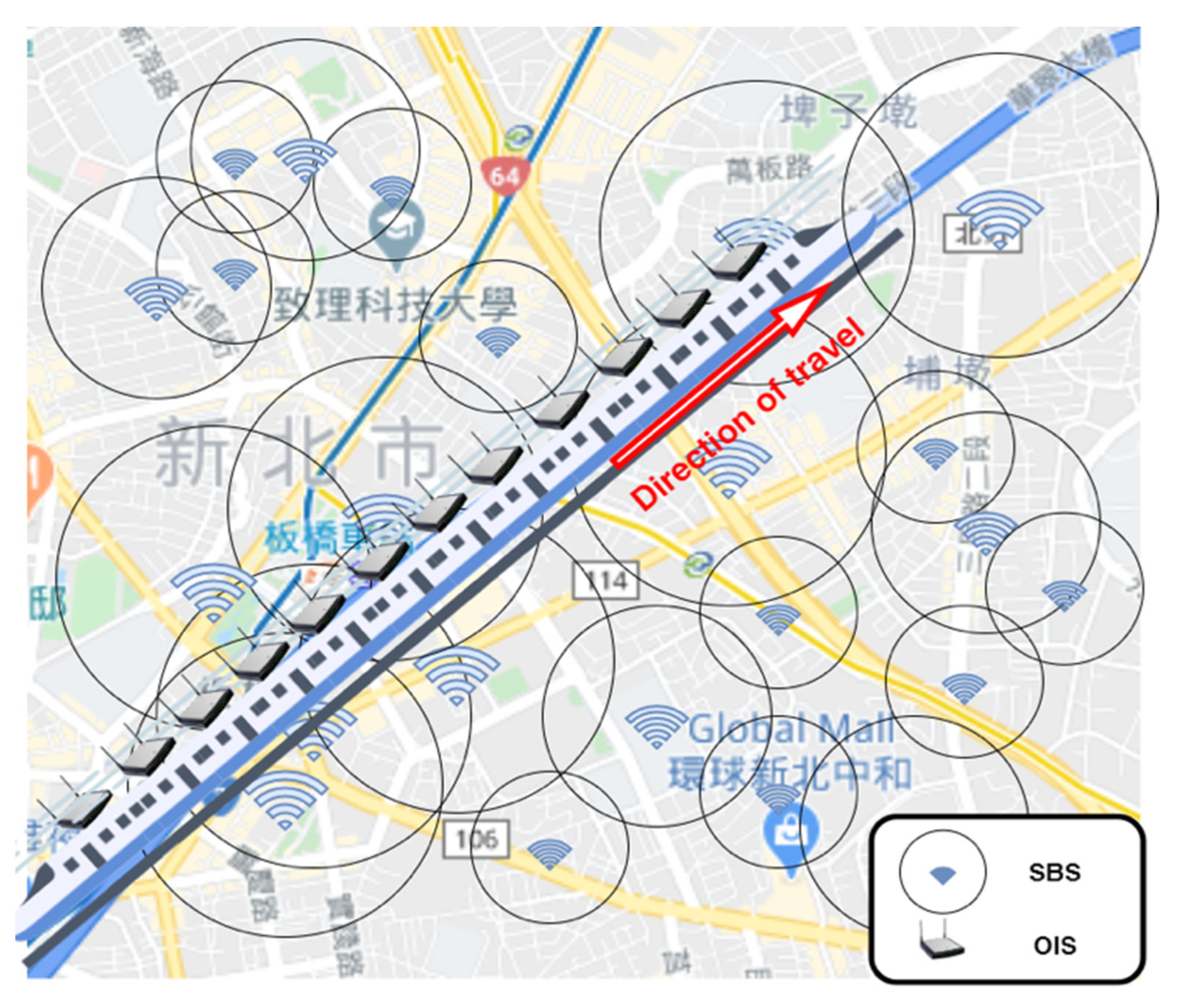
A new handover selection algorithm (applied to the OIS) is proposed in this study. This algorithm utilizes rail paths to categorize SBSs that are deployed in the vicinity of the railway track, automatically regulates the size of each SBS’s coverage area by considering their respective loads and defines several modes to effectively manage these loads. If a handover is necessary, the OIS utilizes positioning to locate SBSs suitable for the handover at the next evaluation time point; after which, it scores these SBSs to identify the best candidate and send a message to the currently connected SBS to transfer all returning transmission data to the selected SBS with the best score. After the OIS is handed over to the most suitable SBS, it can then directly receive the returning transmission data. This process is continually repeated while the car is moving. Due to the “toss (OIS –> currently connected SBS) and catch (next suitable SBS –> OIS)” nature of the data transfer process when observed from the OIS’s perspective, we therefore named the proposed algorithm the “toss-and-catch algorithm”, as shown in Figure 1. By applying this toss-and-catch approach to calculations, data sent to the current location can be effectively redirected to an upcoming location, thereby achieving non-interruptible handovers and reliable data transmission. The simulation results showed that, in most scenarios, the toss-and-catch algorithm outperformed other methods in terms of signal quality and handover connection performance. In a typical fading channel environment (e.g., Nakagami-1 fading), the toss-and-catch algorithm produced, on average, better results than the random SBS selection method with respect to signal quality (approximately 28% improvement), disconnection rate for handover connections (approximately 50% reduction), and processable load ratio (approximately 71% improvement). These positive results open up the possibility for fixed-rail transport operators to provide free connection services (via this connection platform), which would attract more people to use their transport services and create more business opportunities. We believe that this is a good communication transmission approach for fixed-rail mobile terminal equipment in 5G and even more advanced network environments.
This research incorporates efficiency designs derived from multiple viewpoints, and its primary contributions are as follows:
  • Use of OIS movement paths to effectively categorize SBSs that may be encountered:
    The OIS can identify, in advance, the SBSs located close to its movement path and categorize them effectively to optimize their performance. We can then avoid unnecessary handovers and provide a firm foundation for the OIS to perform data transmissions.
  • Automatic adjustment of each SBS’s coverage area and definition of modes:
    Based on their respective loads, the coverage area of each SBS is automatically adjusted and several modes are defined. The loads of the categorized SBSs (environmental changes are also considered) are effectively adjusted through the use of appropriate modes.
  • GPS positioning and received signal strength (RSS) support:
    Using GPS positioning, the SBSs in a large area that are suited for a handover can be identified, such that an OIS is able to determine the best SBS in advance and we are able to identify the actual location of the OIS. After the most suitable SBS has been determined, RSS can then be utilized to enable the timely handover of the connection signal by the OIS.
  • Ability of the OIS to facilitate a handover by evaluating and selecting the most suitable SBS in its path based on the current situation:
    SBSs that are suitable for a handover are individually evaluated. Weighted scoring is performed using three indicators, namely the hold time of the connection between the OIS and an SBS, the RSS of the OIS, and the load capacity of an SBS, with the purpose of identifying the SBS in the OIS’s path that is most suitable for a handover.
  • Simulation of fading in different channel environments:
    Simulations based on different symmetric fading channel environments were performed in this study, with the aim of developing practical SBS selection and handover methods that can be applied to mobile terminal equipment in a realistic context.
The subsequent contents of this article are divided into the four sections as follows: Section 2 is a literature review in which relevant studies are discussed; Section 3 introduces the design of the proposed model and toss-and-catch algorithm by first establishing and defining the model’s relevant parameters and then describing the steps involved in the algorithm process; Section 4 presents and discusses the detailed simulation results to highlight the superior attributes of the proposed method; and Section 5 provides a conclusion for the study in addition to discussing future expectations.

2. Related Work

With the advent of high-speed rails and 5G networks, losses resulting from handovers have now become a pressing issue that cannot be ignored. In one study [2], handover loss relating to identity verification processes was observed among a large number of mobile terminals (which support 5G high-speed rail mobile networks) in high-speed rail cars when they were executing handovers. To address this problem, the authors of that study proposed two pre-handover authentication solutions for fixed-rail transportation that utilize software-defined networking controllers. These solutions can reduce, to negligible levels, the delays that occur when handovers are executed within the coverage range of the SBSs at a destination and thus provide uninterrupted Internet service. However, they did not consider practical responses to address the signal loss arising from changes in channel environments. Panigrahy and Ghosh [3] defined a measurement index for measuring load, the data rate of mobile terminals, and the effects of soft handovers on handover failure rates. In that study, the relative positional relationship between two access points and a mobile terminal during a failed handover attempt was observed, and a mathematical analysis was performed to determine the lower bounds for the failed handover and the probability of unnecessary handovers. Relatedly, Pan et al. [4] proposed two handover procedures for mobile relays in long-term evolution-advanced (LTE-A) high-speed rail networks to ease the message overhead and handover time incurred by the handover procedures in LTE-A specifications.
The challenges associated with high-speed travel include a more severe Doppler effect, delayed handover triggering, and frequent handovers, which, in turn, lead to a reduction in the reliability of wireless communication networks. To determine the current position of a train more accurately, a combination of positioning rules may have to be applied. One example of this approach is a study conducted by Cheng et al. [5], who proposed a solution that utilizes beamforming and positioning information to improve the system handover performance of LTE systems used in high-speed rails. While their results demonstrated the effectiveness of their solution in raising the success rate of handovers, they had only examined situations in which moving trains enjoyed eNodeBs signal coverage and did not consider situations in which there is no signal coverage. Achroufene et al. [6] pointed out that RSS is a simple and low-cost method for realizing positioning capabilities in wireless sensor networks (WSNs). They proposed a method that addresses existing RSS measurement problems and improves the reliability of RSS sources, which is achieved by estimating the position of indoor WSN goal nodes and utilizing non-Gaussian probability density functions to realistically simulate RSS bias and obtain more accurate measurements. However, the positioning component of their approach requires multiple nodes, making it less feasible to implement in places with less wireless network coverage. Zanella and Bardella [7] proposed the averaging of RSS samples (collected from different radio frequency channels) to improve range-finding accuracy. Their analysis results indicated that their method reduces the component of RSS variability by reducing multipath effects and interference. Gao et al. [8] proposed a roadside equipment (RSE) assisted positioning method that incorporates GPS+RSS mixed signal to perform lane-level positioning and claimed that their method is more accurate than GPS while also being less complex as a whole. Their simulation and actual measurement results showed that their method provides better accuracy and can identify the lane on which a target vehicle is driving.
In heterogeneous networks, vertical handovers are an important branch of user mobility as they directly affect network performance (e.g., throughput, packet delay, and call blocking probability). However, the analytical aspect of vertical handover research is fraught with difficulties, including the extreme complexity of network modeling due to topological diversity. With regard to network topology, Duong and Kwon [9] utilized the random deployment and topology diversity reduction methods to enhance the practicality of their proposed approach. On the other hand, many past studies (such as [10,11,12,13,14,15,16,17,18]) have speculated that SBSs will be utilized in 5G networks that are designed to enhance energy savings. Auer et al. [10] quantified the differing levels of power consumed among different types of SBSs. Aleksic et al. [11] proposed a hybrid model capable of assessing converged wireless/optical access network energy efficiency. Huang et al. [12] presented both distributed and centralized optimization methods that addressed problems pertaining to SBS cluster coverage optimization. Wang et al. [13] investigated the implementation of quality-of-service requirements and interference mitigation for improving transmission efficiency. Chung [14] explored several transmission algorithms that allowed for data-rate needs to be met even when a variety of different SBS deployment strategies were utilized, while simultaneously minimizing the total energy consumed by the transceivers of all the BSs (i.e., the SBSs and the MBS). Chung [15] proposed an algorithm designed to achieve the maximum possible reduction of the combined power consumed by the transceivers of all the BSs, while also ensuring that comprehensive wireless signal coverage is provided to users in various scenarios. Furthermore, Lu et al. [16] discussed the effects of power adjustments on the handovers conducted within 5G high-speed rail mobile networks and tried their best to adjust power levels to levels that overlapped with the handover process, so as to avoid wasting resources unnecessarily. At the same time, Xu et al. [17] recommended the use of modes in which SBSs are defined based on load levels. Moreover, Xie et al. [18] developed a continuous-time Markov chain model for quantifying the survivability of a network that is facing extensive failures due to events such as security attacks, natural disasters, and common mode software and hardware failures. Relatedly, Pons et al. [19] proposed a vertical handover decision algorithm for improving the energy efficiency of a battery-limited device with both LTE and wireless local area network connection interfaces. In addition, Catak et al. [20] proposed a hexagonal generalized frequency division multiplexing model using polyphase decomposition to reduce computational complexity and latency for transceivers in 5G systems and beyond.
On the other hand, Ma et al. [21] proposed the integration of a self-organizing network (SON) with 5G architecture, such that the SON is able to independently manage the relationship between an SBS and other surrounding SBSs and, thus, effectively achieve load balancing, increased network capacity, and lower costs. As the signaling aspect of the original SON location management method was not practical and overly complicated, Aqeeli et al. [22] proposed a solution that is easier to implement and minimizes signaling complexity. Although this solution was revealed in that study to be suboptimal compared to the original method, it was able to achieve excellent energy-saving results and reduce signaling load. Even though an SON can reduce the complexity and cost of network operations and enable independent network optimization, SON functions differ in terms of their time scales and objectives, which may lead to operation conflicts and poorer network performance and consequently increase the need to develop SON coordination solutions. Qin et al. [23] proposed an analysis model that utilizes the M time-scale Markov decision process, in which the SON decisions made for every time scale all take into account the network effects of SON decisions made for other M-1 time scales, and they applied the Q-learning algorithm to learning history and experience in order to implement a stable control strategy. The simulation results of that study showed that the proposed SON coordination solution improves network performance with respect to various quality of experience requirements, while also ensuring the stable operation of wireless networks.
All of these studies [2,3,4,5,6,7,8,9,10,11,12,13,14,15,16,17,18,19,20,21,22,23] have provided alternatives for enhancing specific aspects of system performance and thus contributed significantly to the development of 5G network systems. Nonetheless, none of them have managed to provide a comprehensive investigation of potential means for implementing SBS selection and handover with a focus on resource management and a fixed-rail transportation setting. The accelerating pace of technological progress has made fixed-rail transportation the commuting mode of choice for many people as it is fast and convenient, and with the ubiquity of smart handheld devices in our daily lives, commuters on fixed-rail transportation now spend most of their commuting time using their phones or sending and receiving messages on their phones. These trends, coupled with the gradual adoption of 5G SBS networks and various emerging applications, have made seamless mobility a primary concern for many people. In light of these considerations, it is crucial that we design an effective resource management mechanism for improving fixed-rail transportation mobile terminals and enabling effective transmission and handovers in SBS networks. For these reasons, it is necessary to further examine this topic.

3. Model Assumption and Toss-and-Catch Algorithm

The scenario being considered is presented in Figure 2, which shows a moving train with one OIS in every car. Each OIS runs the same toss-and-catch algorithm independently such that the OISs do not influence each other. Based on this assumption, this study only looks at and describes a single OIS. As for SBSs, they are assumed to be randomly deployed within the vicinity of the track. The SBSs are categorized into main SBSs (MSBSs), auxiliary SBSs (ASBSs), and other SBSs (OSBs). MSBSs are the prioritized SBSs for conducting data transmission and handovers with OISs. ASBSs support MSBSs and are used when an OIS requires a handover but is unable to identify a suitable MSBS or there are no available MSBSs within the vicinity. All other SBSs that are not MSBSs or ASBSs are categorized as OSBSs. The SBS categorization is detailed in Section 3.1.2.
It is assumed that every SBS is equipped with the same hardware, including a GPS device with high positioning accuracy. Moreover, the OIS and every SBS are assumed to have the same capacity. The preset signal coverage radius of an activated SBS is R (measured in meter), which can be adjusted to a maximum of 2R when the SBS’s load increases. To establish the relationship between change in load and coverage radius, we defined γ i as the load ratio of SBS i and expressed it as
γ i = α i β i .
In (1), α i represents the current load of SBS i (the current load refers to the sum of the traffic being or to be processed by the SBS), β i represents the total capacity of SBS i, and 0 γ i 1 . Assuming that the load is evenly distributed within the geographical environment, the coverage radius of the SBS varies alongside the load. We denoted d i as the coverage radius of SBS i and defined it as
d i = { R , 0 γ i 0.5 ( 1 + γ i ) × R , 0.5 < γ i 1 .
Based on γ i , we then established three modes for SBS i: namely, the boot preset mode, the normal mode, and the super mode. Boot preset mode: when 0 γ i 0.5 , d i = R . Normal mode: when 0.5 < γ i < 1 , d i = ( 1 + γ i ) × R . Super mode: when γ i = 1 , d i = 2 R . In addition, the coverage radius of the OIS was also set to and fixed at 2R, so as to increase the likelihood of mutual data transmission and reception occurring between the SBSs deployed in the vicinity of the track.
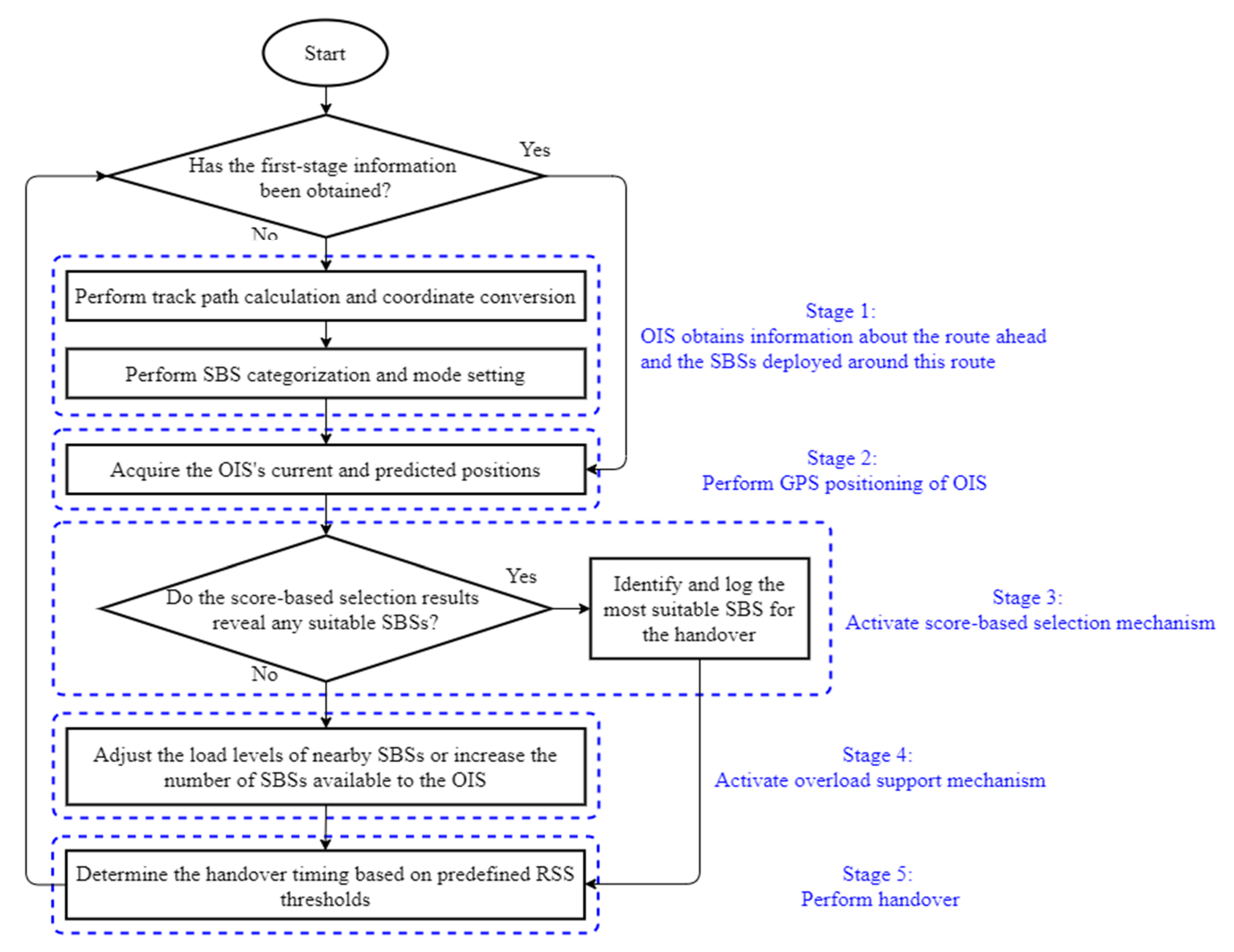
Figure 3 shows the flowchart of the proposed toss-and-catch algorithm. The algorithm’s operation can be broken down into five stages. Stage 1: The OIS obtains information about the route ahead and the SBSs deployed around this route. This stage covers track path calculation and coordinate conversion, and SBS categorization and mode setting. Stage 2: The GPS positioning of the OIS is performed using reliable GPS equipment to obtain its real-time coordinates. Stage 3: A score-based selection mechanism is used to identify and log the most suitable SBS for the handover to be performed during the next evaluation time point. Stage 4: The overload support mechanism comes into play when the score-based mechanism fails to identify a suitable SBS. In this situation, the overload support mechanism is used to appropriately adjust the load levels of nearby SBSs or to increase the number of SBSs available to the OIS, and the updated information concerning the SBSs’ sizes and modes are then used as the basis for the next round of calculations. Stage 5: During the handover stage, a handover to the most suitable SBS (as identified through the score-based selection mechanism) is performed.

3.1. Gathering of Information about the Route Ahead and the SBSs Deployed around This Route

3.1.1. Track Path Calculation and Coordinate Conversion

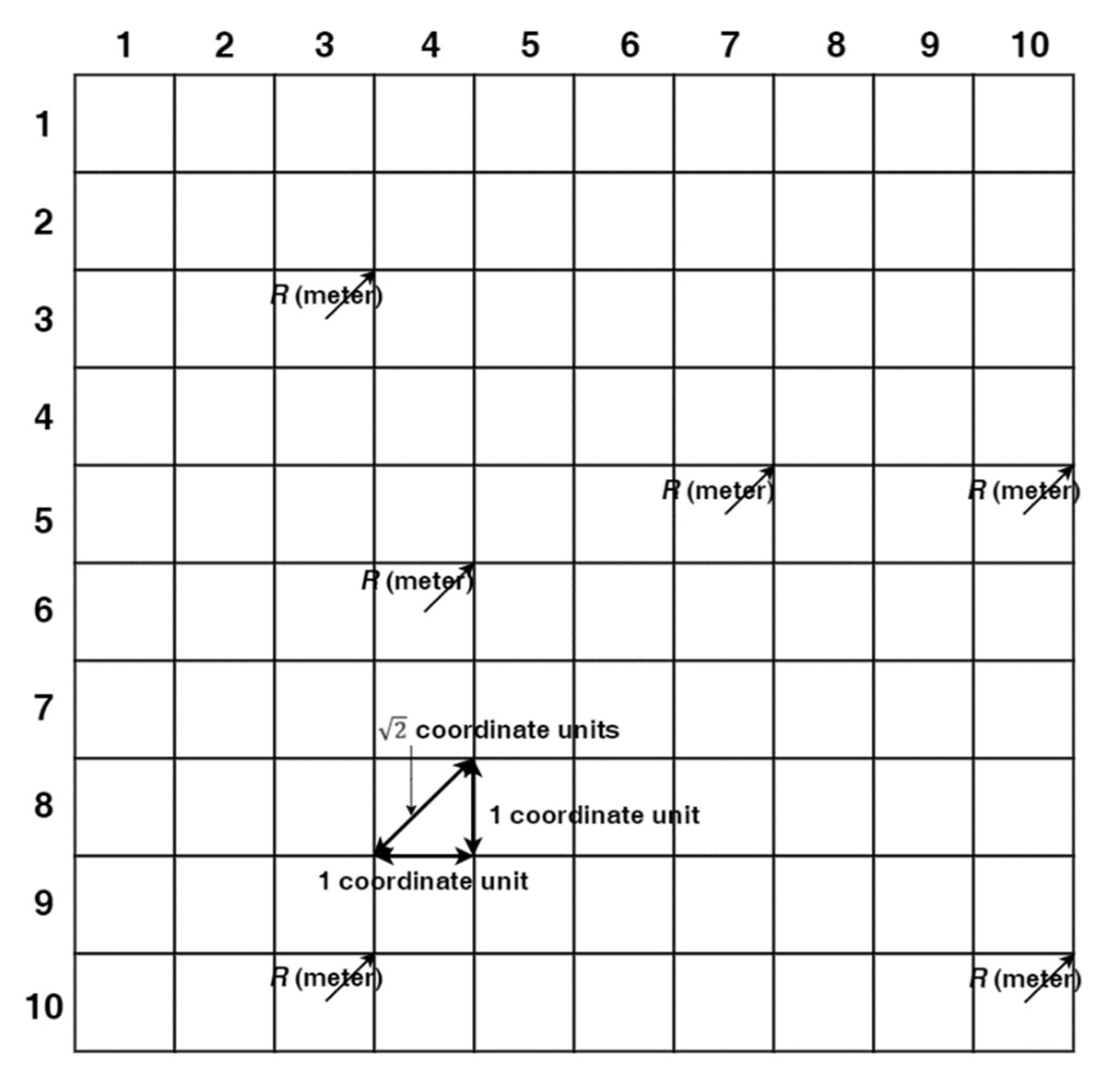
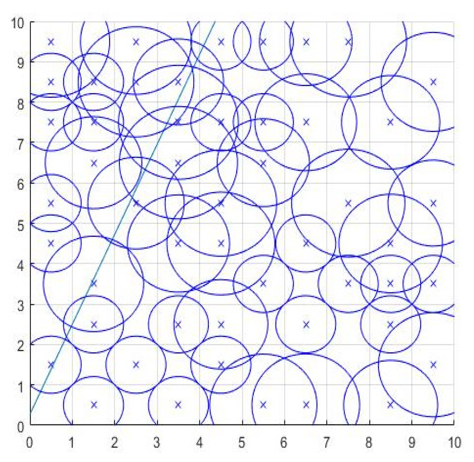
As shown in Figure 4, a kernel is first defined before calculating the track path. This kernel is a square with a side length of 10 coordinate units, with the length from the center to the vertex of each 1 × 1 small square being defined as the preset signal coverage radius R of the actual SBS, and this describes the relationship between the kernel coordinates and their corresponding actual geographic coordinates. Using trigonometric functions, it can be deduced that the ratio of the side length of each 1 × 1 square to the actual geographic length is one coordinate unit: 2 R m. Each time the OIS obtains information relating to the topologic conditions ahead of the train, it must select a kernel block (with an actual geographic area of 10 2 R × 10 2 R m2) and obtain information on the block (SBSs’ coordinates, load, coverage, and train track path).
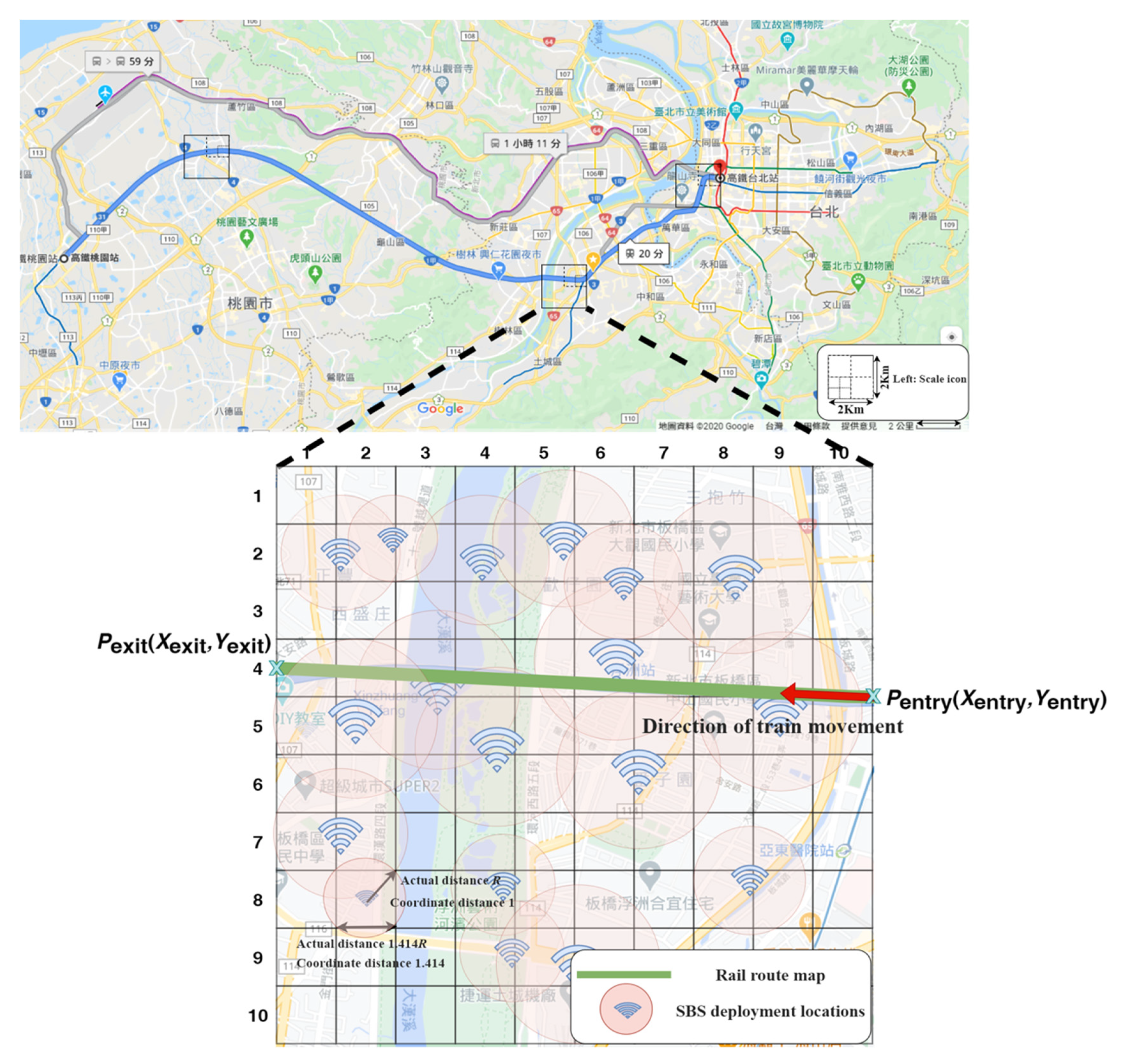
Figure 5 presents a Google Map showing the Taiwan high speed rail (THSR) Taipei Station and the THSR Taoyuan Station, providing an example that illustrates how kernel block selection is implemented on an actual map. In this figure, the blue solid line plots the track route from the THSR Taipei Station to the THSR Taoyuan Station, while the black bordered boxes are the kernels. A close-up of one of the kernels reveals the schematic relationship between the track and the SBSs after coordinate conversion (the conversion to the kernel coordinate system is described in Appendix A).
As the overall curvature of the track is not significant and the geographic coordinate range that is selected each time represents only a very small segment of the track, the track curvature within each selected block range is in fact very small. To facilitate modeling and calculations, we approximated each selected track path using a linear equation with two unknowns, which is given by [24]
y = m x + b ,
where m is the slope and b is the constant term. m and b can be obtained by calculating the two intersection points, P entry ( X entry , Y entry ) and P exit ( X exit , Y exit ) , of the track and the boundary of the selected block range and bringing in (3). The distance between P entry ( X entry , Y entry ) and P exit ( X exit , Y exit ) can be expressed as [24]
D rail ( P entry , P exit ) = ( X entry X exit ) 2 + ( Y entry Y exit ) 2 .
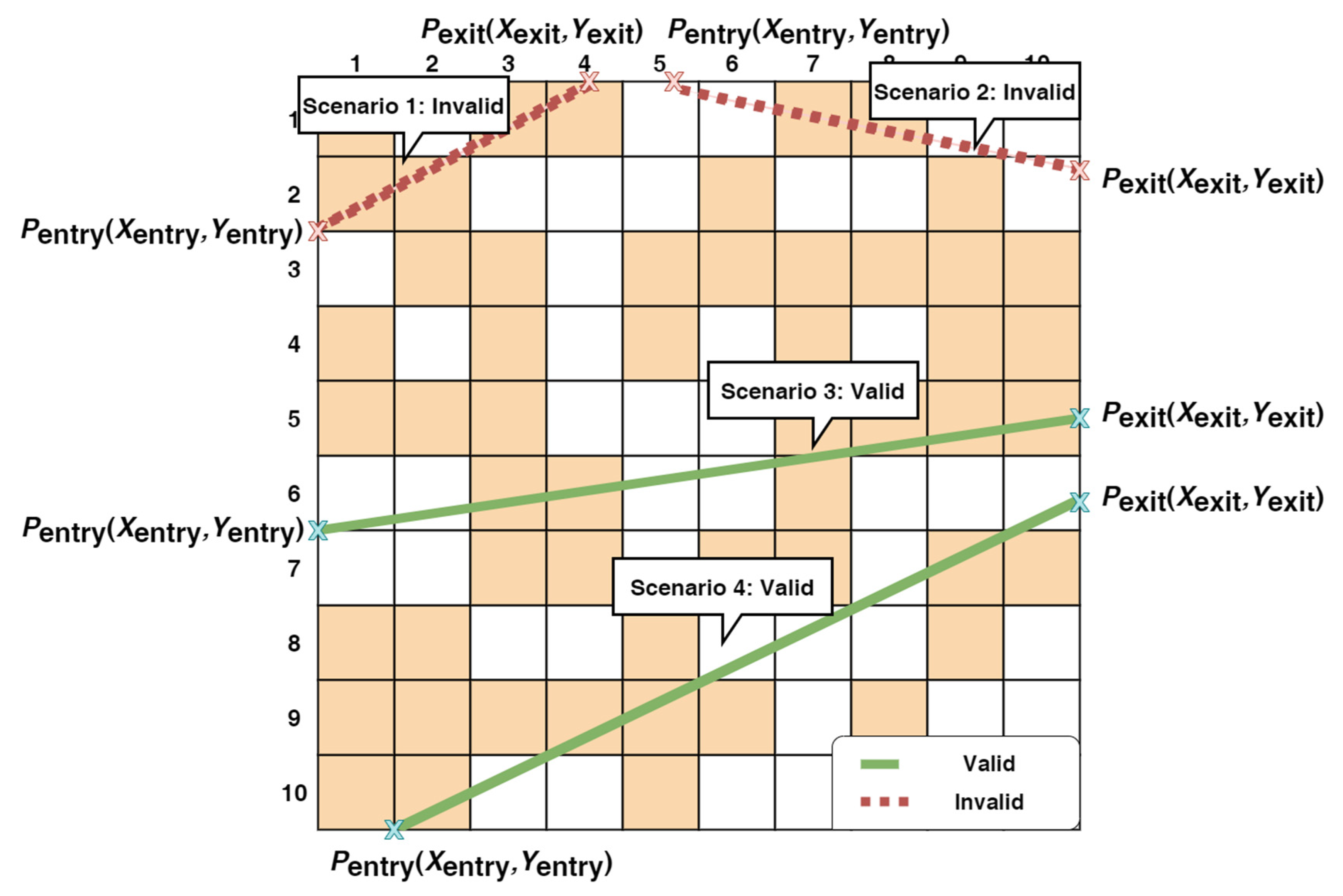
A range is always selected randomly by the kernel, and consequently, the coordinate point of the OIS (namely, P entry ( X entry , Y entry ) ) when it enters the kernel range is random. To ensure that each selected track is sufficiently long, we defined D rail ( P entry , P exit ) to be valid only when it is greater than or equal to 90% of the kernel’s side length, as shown in Figure 6; when D rail ( P entry , P exit ) is less than 90% of the kernel’s side length, the selection is repeated until a valid length is achieved for D rail ( P entry , P exit ) . It should be noted that whenever the OIS leaves the current selected range (with the exit point being P exit ( X exit , Y exit ) ), the selection process is repeated on the path ahead of the train to continuously obtain track and topology information until the train arrives at its destination.
After obtaining the track equation, the relative relationship between the track and nearby SBSs can then be established through the kernel coordinate system, such that SBS categorization and SBS coverage adjustments can be appropriately carried out.

3.1.2. SBS Categorization and Mode Setting

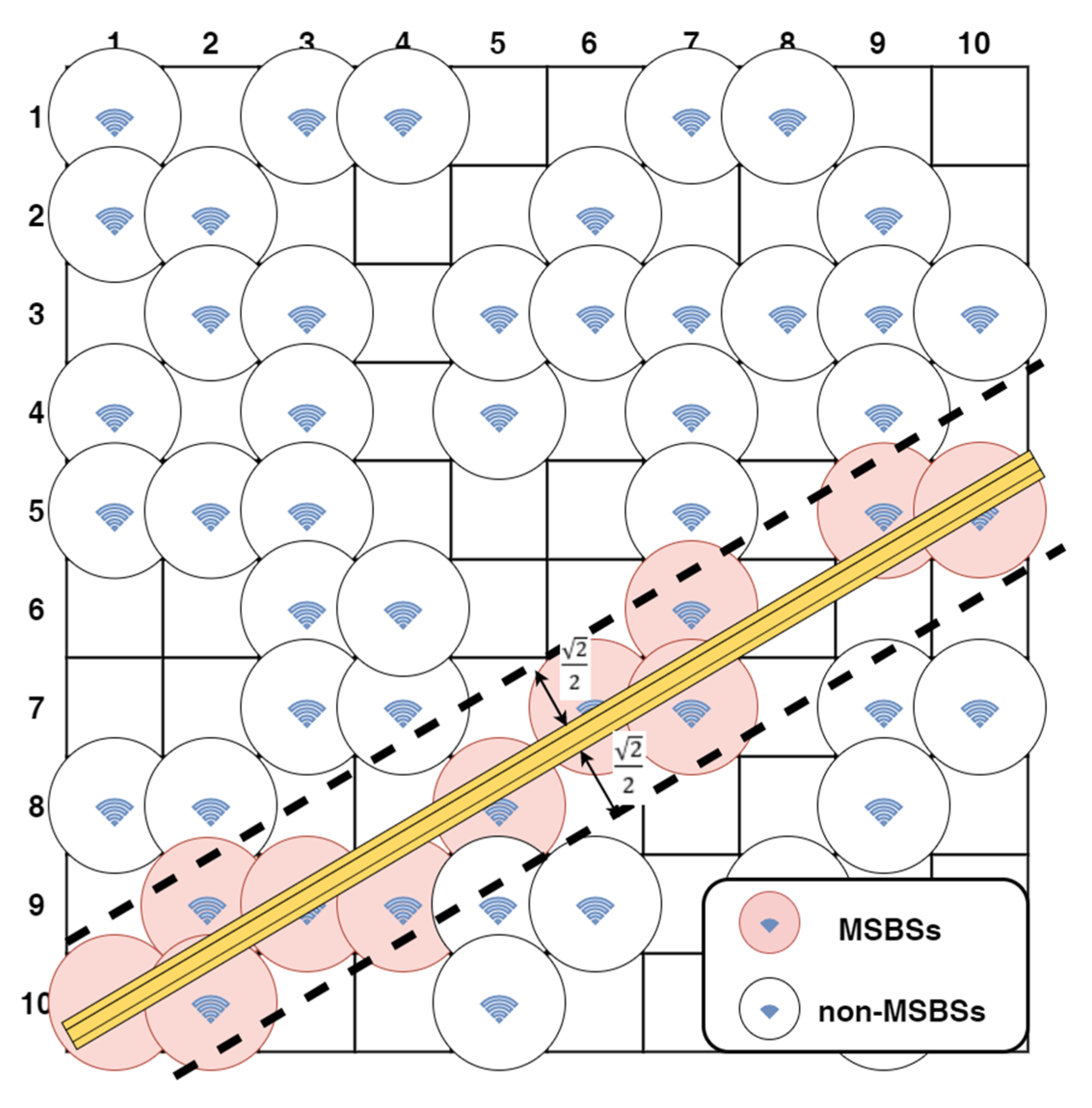
The SBSs within the kernel range (collectively represented by ) are first sorted into two categories, namely MSBSs (collectively represented by MSBS ) and non-MSBSs (collectively represented by non - MSBS ). The nearby SBSs that the OIS has a high chance of coming into contact with are marked as MSBSs. In this marking process, we defined ( X i , Y i ) as the coordinates of SBS i in the kernel coordinate system, and the shortest distance L i between each SBS (within ) and the track is expressed as [24]
L i = | m X i Y i + b | m 2 + 1 ,   i .
An SBS is marked as an MSBS when L i 2 / 2 , and as a non-MSBS when L i > 2 / 2 . This criterion is visualized as a conceptual diagram in Figure 7. The rationale for establishing this criterion is as follows: because R (i.e., boot preset mode) is the preset coverage radius of an SBS in the actual geographic coordinate system, the OIS must be within the coverage of this SBS when the shortest distance between this SBS and the track is within R. Moreover, the conversion of the actual geographic coordinate system to the kernel coordinate system shows that length R in the actual geographic coordinate system is equivalent to length 2 / 2 in the kernel coordinate system. It should be noted that the modes of these MSBSs are subsequently set to super mode to maximize signal coverage in an attempt to cover the entire track. After an OIS exits the kernel range, SBS i within MSBS (in the range) is switched to the appropriate modes based on γ i (i.e., the adjustment is based on (2)).
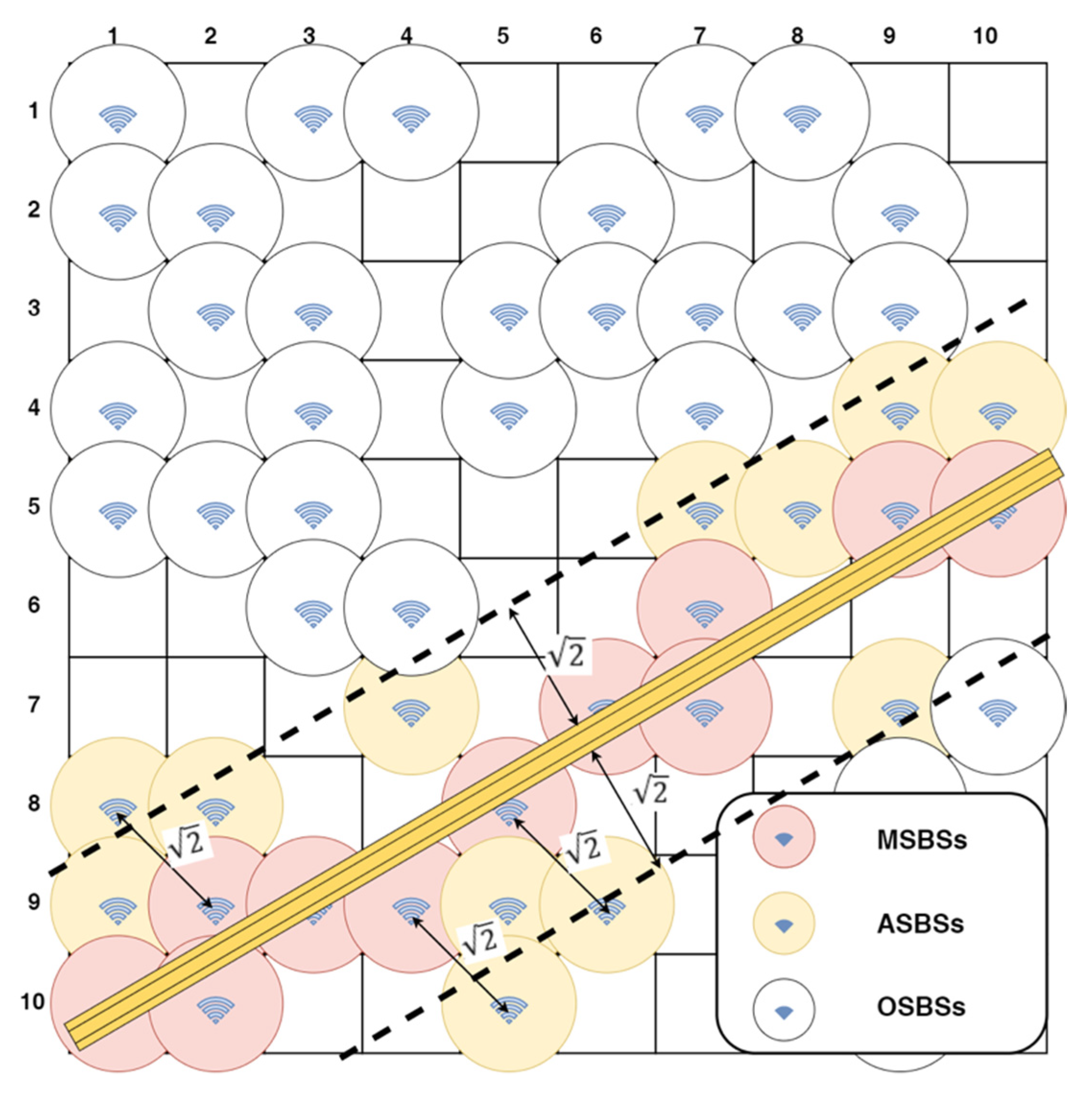
After marking the MSBSs, the next step is to subcategorize the non-MSBSs. When an OIS requires a handover but it is unable to identify a suitable MSBS or there are no available MSBSs within the vicinity, it then needs to select suitable auxiliary SBSs from the non - MSBS . These selected SBSs are marked as ASBSs (collectively represented by ASBS ), while the remaining SBSs are marked as OSBSs (collectively represented by OSBS ). In the ASBS marking process, the distance between all SBSs within non - MSBS and all SBSs within MSBS is denoted as D j i , and the shortest distance between all SBSs within non - MSBS and the track is denoted as L j . D j i and L j are calculated as follows [24]:
D j i = ( X j X i ) 2 + ( Y j Y i ) 2 , j non - MSBS ,   i MSBS ,
L j = | m X j Y j + b | m 2 + 1 ,   j non - MSBS .
SBS j is marked as an ASBS when D j i 2 or L j 2 or as an OSBS if these criteria are not met. These criteria are visualized as a conceptual diagram in Figure 8. The rationale for establishing these criteria is as follows: because 2R (i.e., super mode) is set as the signal coverage radius of an MSBS in the actual geographic coordinate system, SBS j is able support and share the load handled by SBS i or provide coverage to OIS when the distance between SBS i from MSBS and SBS j from non - MSBS is within 2R, or when the shortest distance between SBS j and the track is within 2R. Moreover, the conversion of the actual geographic coordinate system to the kernel coordinate system shows that length 2R in the actual geographic coordinate system is equivalent to length 2 in the kernel coordinate system. These ASBSs are, in principle, switched to the appropriate mode based on their respective γ i . However, when an OIS requires a handover but it is unable to identify suitable SBSs, the algorithm activates the overload support mechanism and sets these ASBSs to super mode. As for OSBSs, they are switched to the appropriate mode based on their respective γ i .
It should be pointed out that no categorized SBSs are recategorized unless the track in question is malfunctioning or subjected to repairs or changes were made to its network topology.

3.2. GPS Positioning of OIS

The OIS’s positioning information is obtained at set intervals using GPS. t n (n = 0, 1, 2, 3, …) is defined as the time series of the location data as obtained by the OIS’s GPS. When the OIS is performing a kernel selection, the only located-related information that it obtains is that relating the SBSs. As we lack information regarding the OIS’s current position, the OIS’s GPS hardware is therefore used to obtain its latitude and longitude coordinates at t n , which are then converted for use in the kernel coordinate system; the OIS’s relative positional relationship (with the nearby SBSs ahead of it) is subsequently obtained to determine if a handover is necessary at t n + 1 , as well as to plan ahead and identify SBS options for the handover. In Figure 9, the train is in Cell B at t 0 , and it is in the process of determining its current position and whether a handover is necessary at t 1 based on this position; at the same time, it is also attempting to identify suitable SBS options for the handover at its estimated location (Cell D or Cell F) at t 1 .
With t n being the current time point, the kernel coordinates of the OIS at t n were defined as ( T x t n , T y t n ) , and v t n was defined as the OIS’s velocity (in the kernel coordinate system) at t n . The velocity components for directions x and y were v x t n and v y t n , respectively, and expressed as:
v x t n = v t n cos tan 1 m ,
v y t n = v t n sin tan 1 m .
Assuming a minimal value for t n + 1 t n , the coordinates ( T x t n + 1 , T y t n + 1 ) of OIS at t n + 1 were expressed as:
T x t n + 1 = T x t n + v x t n ( t n + 1 t n ) ,
T y t n + 1 = T y t n + v y t n ( t n + 1 t n ) .
The acquisition of the OIS’s current and predicted positions at t n and t n + 1 facilitates subsequent calculations performed by the score-based selection and overload support mechanisms and during the handover stage.

3.3. Score-Based Selection Mechanism

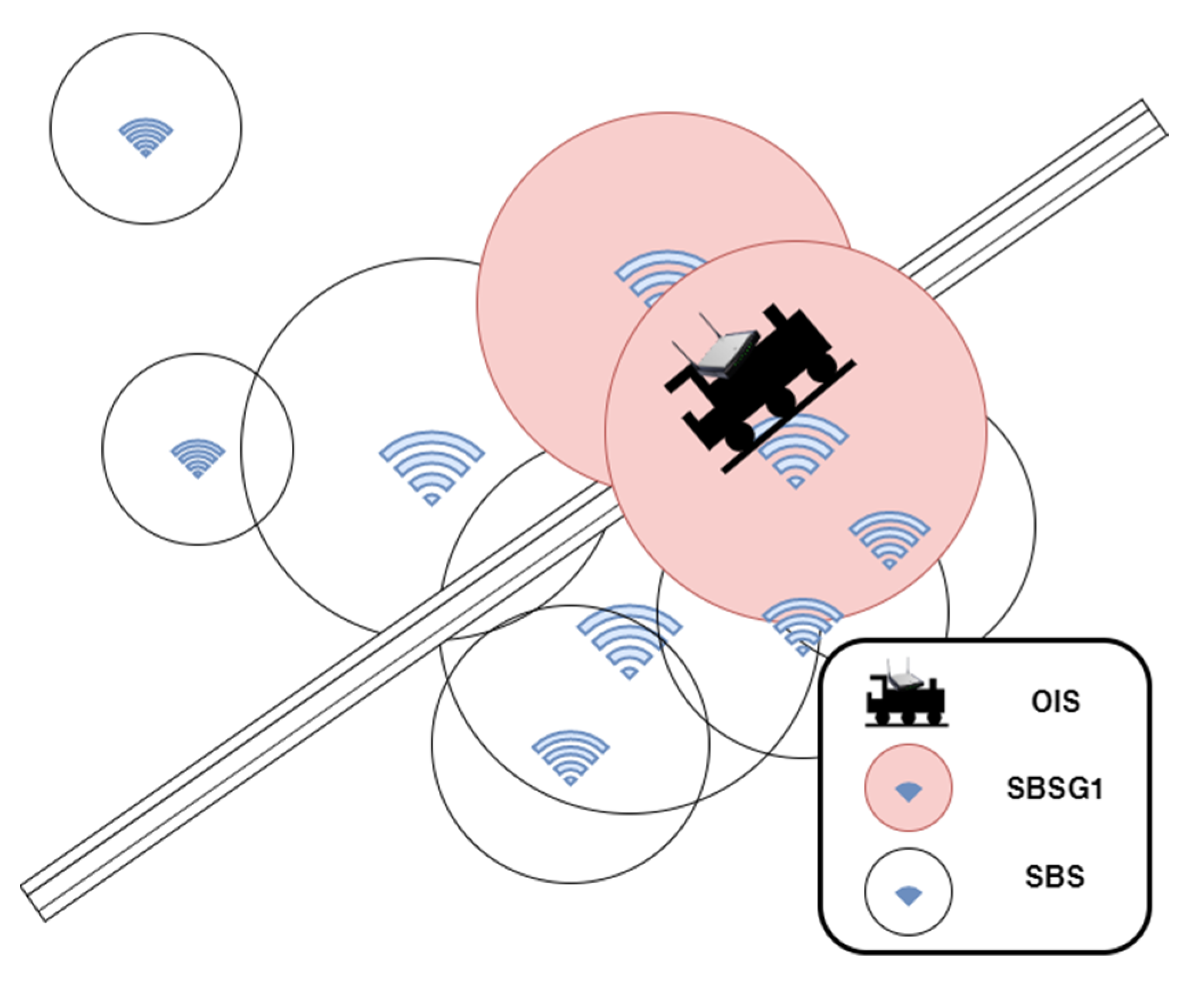
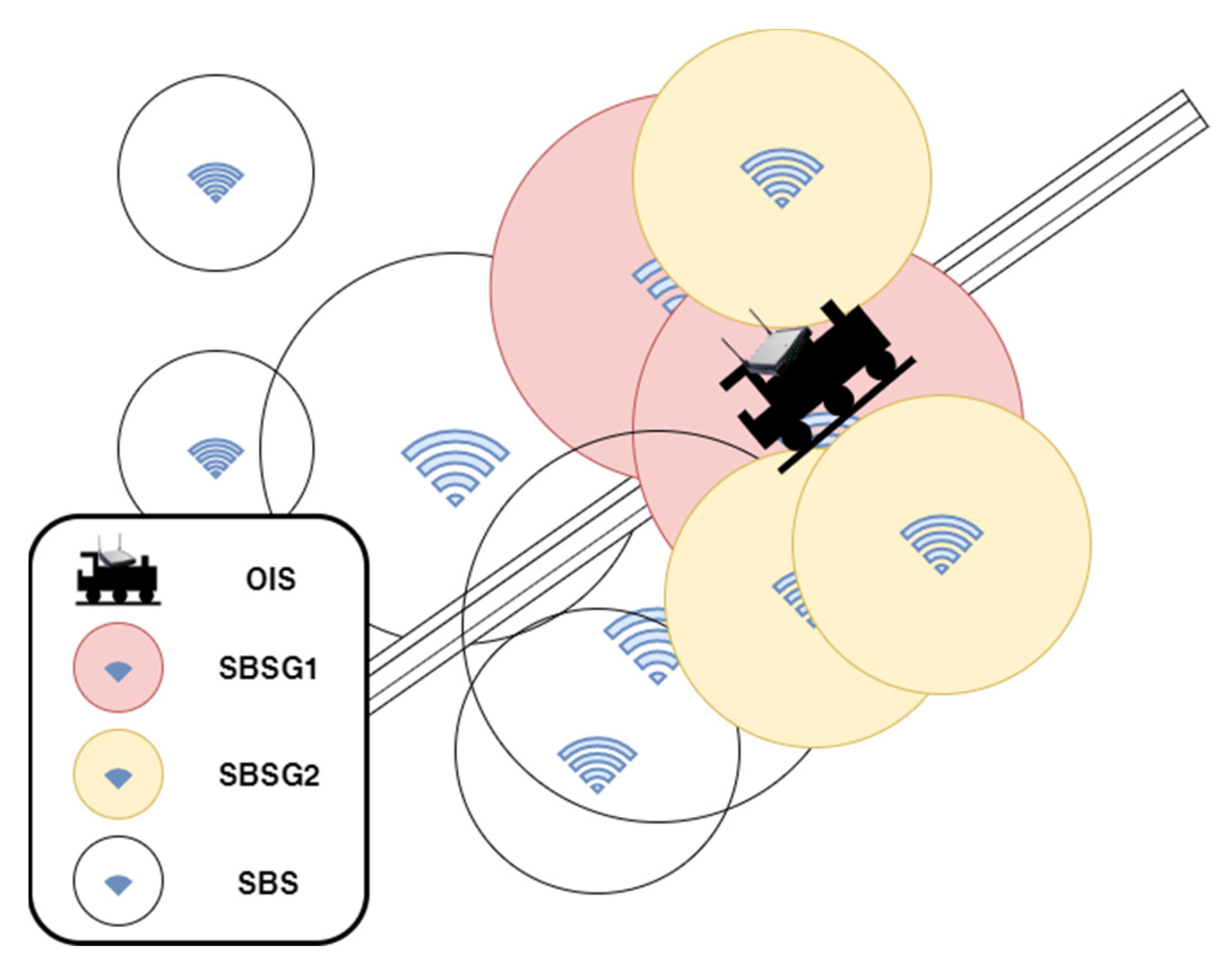
We defined SBSG1 as the set of SBSs with which the OIS can transmit and receive data mutually at t n + 1 , as shown in Figure 10. The SBSs in SBSG1 are the possible options for a handover of the OIS at t n + 1 .
This section covers the scoring and sorting of the SBSs in SBSG1. The score-based selection mechanism consists of two components, the first being the introduction of parameters required for score-based selection and the second being scoring method of the score-based selection mechanism. The scoring method comprises the following three stages: In the first stage, the OIS’s connection holds time with each of the SBSs in SBSG1 (which the OIS is coming into contact with) is scored; moving into the second stage, the maximum RSS that the OIS can achieve with each SBS in SBSG1 (which the OIS is coming into contact with) is scored; and during the third stage, the OIS load that each SBS in SBSG1 (which the OIS is coming into contact with) can handle is scored. The scores obtained during these three stages are weight-averaged and ranked, with the highest-scoring SBS being logged.

3.3.1. Data Collection

(1)
Introduction of parameters for scoring of OIS connection hold time
At this stage, the required information include the slope m and constant b as obtained through the track equation described in Section 3.1.1, ( X i , Y i ) , the mode settings described in Section 3.1.2, and the predicted position of the OIS at t n + 1 as described in Section 3.2 (assuming that t n is the current time point).
(2)
Introduction of parameters for scoring of maximum RSS available to the OIS
For this stage, the parameters required include the ones needed in the first stage as well as the information obtained in the first stage.
(3)
Introduction of parameters for scoring of OIS load that can be processed
Moving into this stage, the parameters required include the predicted position of the OIS at t n + 1 as described in Section 3.2 (assuming that t n is the current time point), and the load information of the SBSs that can conduct an OIS handover.

3.3.2. Scoring and Ranking

(1)
Scoring of OIS connection hold time ( s c o r e hold )
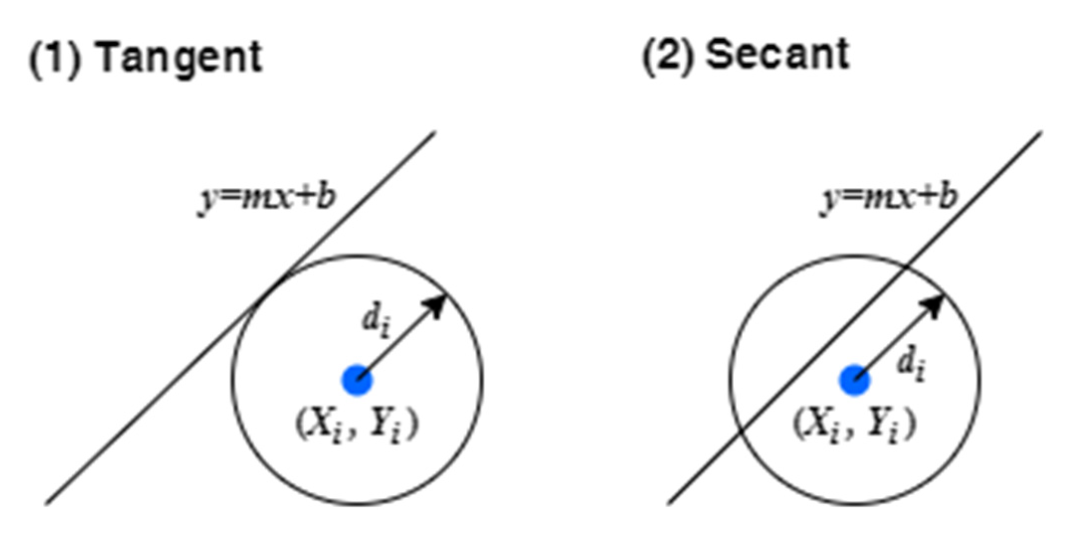
When the train increases its moving speed, the time that the OIS spends within the proximity of an SBS becomes shorter, possibly leading to more frequent handovers. If the OIS determines that a handover is necessary at t n + 1 , it would select a suitable SBS from SBSG1 for the handover. By selecting an SBS that allows for a longer connection hold time, we can reduce the frequency of handovers. With respect to the geometric relationship between the track equation and the SBS currently being scored, one of two possible scenarios occurs: (1) the track equation is tangent to the SBS; or (2) the track equation is secant to the SBS. Figure 11 illustrates these two scenarios for this geometric relationship. A score of 0 is assigned for Scenario 1; and as for Scenario 2, the scoring method is described below.
The circle equation of SBS i can be expressed as [24]
( x X i ) 2 + ( y Y i ) 2 = d i 2 .  
Through (3) and (12), we can obtain the two cut point coordinates ( P S 1 x , P S 1 y ) and ( P S 2 x , P S 2 y ) of the track equation and SBS i. They can be expressed as
( P S 1 x , P S 1 y ) = ( B + B 2 4 A C 2 A , m B + B 2 4 A C 2 A + b ) ,  
( P S 2 x , P S 2 y ) = ( B B 2 4 A C 2 A , m B B 2 4 A C 2 A + b ) ,  
where
A = m 2 + 1 ,  
B = 2 X i + 2 m b 2 m Y i ,  
C = X i 2 + b 2 2 b Y i + Y i 2 d i 2 .  
We defined D sec ant as the secant distance between the two points ( P S 1 x , P S 1 y ) and ( P S 2 x , P S 2 y ) , and expressed it as
D sec ant = ( B 2 4 A C A ) 2 ( m B 2 4 A C A ) 2 .  
We denoted T hold as the OIS’s connection hold time with the SBS and defined it as
T hold = D sec ant v t n .  
The connection hold time s c o r e hold was defined as
s c o r e hold = T hold 2 d i v t n × 100 .  
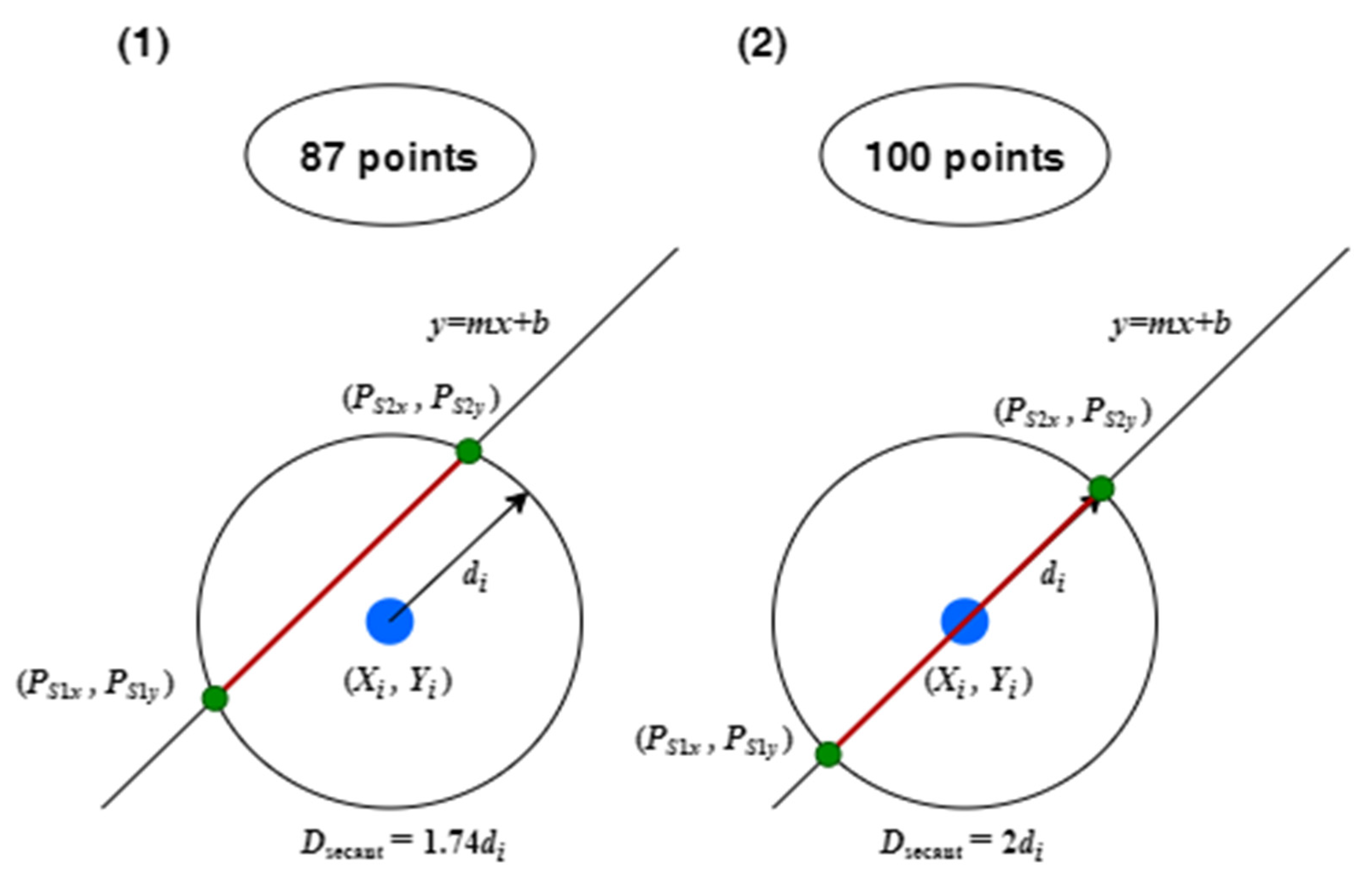
The track equation intersecting the SBS emission center indicates the maximum connection hold time that can be achieved; therefore, a s c o r e hold of 100 is given when this occurs. When the track deviates from the SBS emission center, connection hold time becomes shorter, and a lower score is given. For example, consider the two secant scenarios as shown in Figure 12. If the secant lengths are 1.74 d i and 2 d i , the scores (as calculated via (20)) given are 87 and 100, respectively.
(2)
Scoring of maximum RSS available to the OIS ( s c o r e RSSmax )
Signal quality is important in the communication process. By selecting an SBS that offers more RSS, the OIS is able to increase the average strength of the signals that it receives. With P RX denoting the OIS’s received power, RSS is defined as [25]
RSS = 10 log P RX .  
To the simplify the process, the Friis free space model [25] was used to calculate P RX ; hence, RSS can be further expressed as
RSS = 10 log P TX G TX G RX λ 2 ( 4 π ) 2 l 2 L ,  
where P TX is the power emitted by the transmitter antenna, G TX is transmitter antenna gain, G RX is the receiver antenna gain, λ is electromagnetic wave wavelength, l is the distance between the receiver and transmitter, and L is the system dissipation factor.
For the same SBS, G TX G RX λ 2 ( 4 π ) 2 L is a fixed value defined as K ; hence, RSS can be simplified into
RSS = 10 log P TX K l 2 .  
To facilitate calculations, we defined RSS s as
RSS s = 10 log l 2 ,  
which serves as a substitute for calculating RSS. Let ( P S x , P S y ) denote the center point of the two cut points ( P S 1 x , P S 1 y ) and ( P S 2 x , P S 2 y ) . The maximum and minimum RSSs values of the SBS i are found at ( P S x , P S y ) and ( P S 1 x , P S 1 y ) (or ( P S 2 x , P S 2 y ) ), and the corresponding l values are, respectively, defined as l max and l min
l max = ( X i P S x ) 2 + ( Y i P S y ) 2 ,
l min = ( X i P S 1 x ) 2 + ( Y i P S 1 y ) 2 .  
By standardizing RSSs, the score for the maximum RSS available to the OIS, namely s c o r e RSSmax , can be expressed as
s c o r e RSSmax = 100 10 log l 2 ( 10 log l max 2 ) ( 10 log l min 2 ( 10 log l max 2 ) 100 ) = 100 log d i ( d i l ) .
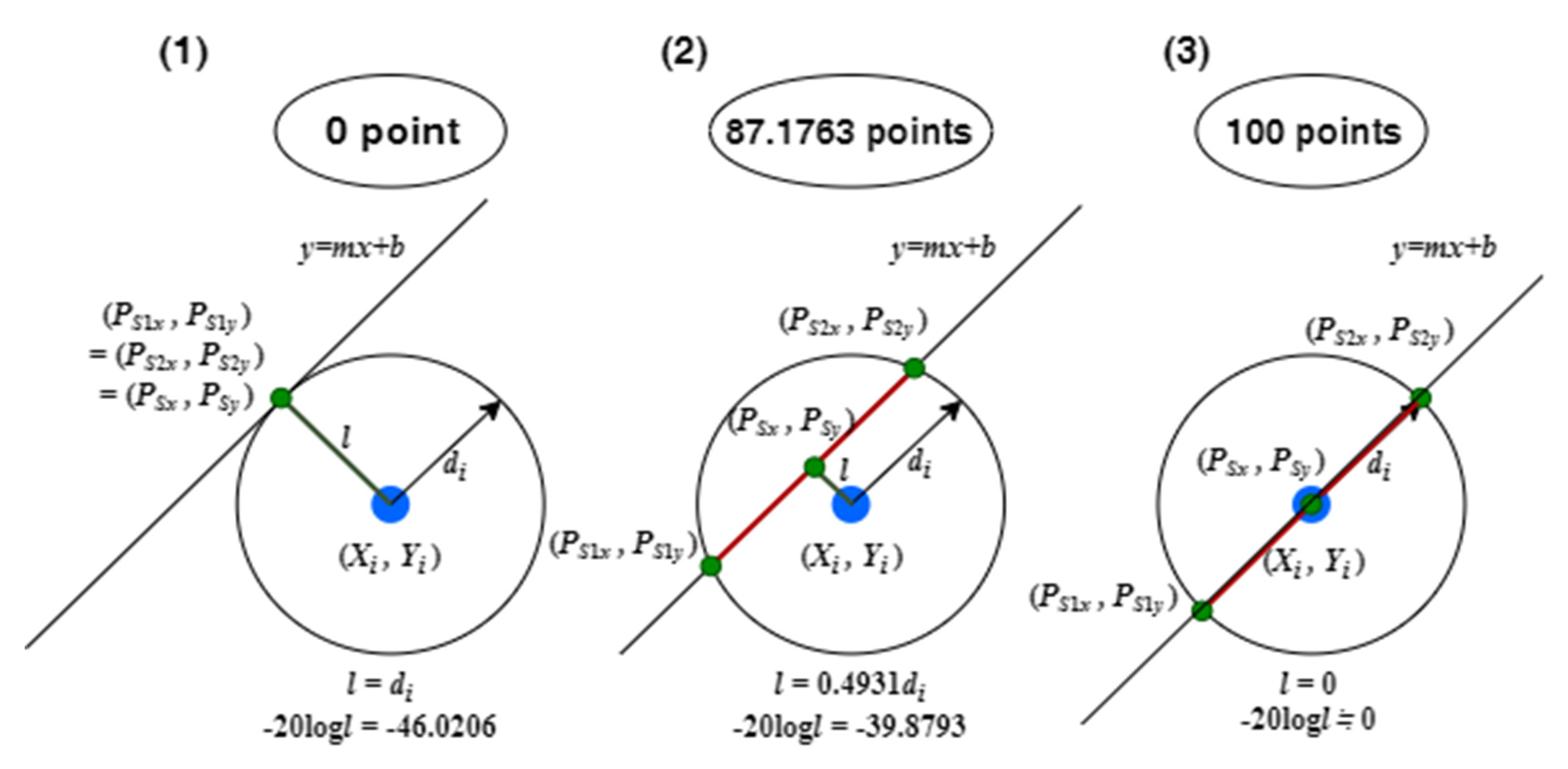
The larger the value of l , the lower the score. A score of 0 is given when l = d i . When l < d i , the shorter the distance between the OIS and the SBS, the higher the score with 100 being the maximum. Figure 13 presents the following three scenarios: (1) the track equation is tangent to the SBS; (2) the track equation is secant to the SBS; and (3) the track equation passes the SBS center. In Scenario 1, l = d i and s c o r e RSSmax is therefore 0; in Scenario 2, l = 0.4931 d i and s c o r e RSSmax is therefore 87.1763; and in Scenario 3, l = 0 , and s c o r e RSSmax is therefore 100.
(3)
Scoring of OIS load that can be processed ( s c o r e load )
In addition to the two considerations discussed above, we also took into account whether the selected SBS can handle the OIS’s load; hence, OIS must determine the proportion of its load that the SBS can handle. To simplify subsequent descriptions, we denoted ϕ i as the no-load ratio of SBS i and defined it as
ϕ i = 1 γ i .  
The OIS’s load ratio is denoted as ψ and obtained by substituting the load values of “SBS i” in the numerator and denominator of (1) with the load values of “OIS”. We defined the score s c o r e load for the OIS load that can be processed by SBS i as
s c o r e load = { 100 , ϕ i ψ ϕ i ψ × 100 , ϕ i < ψ .  
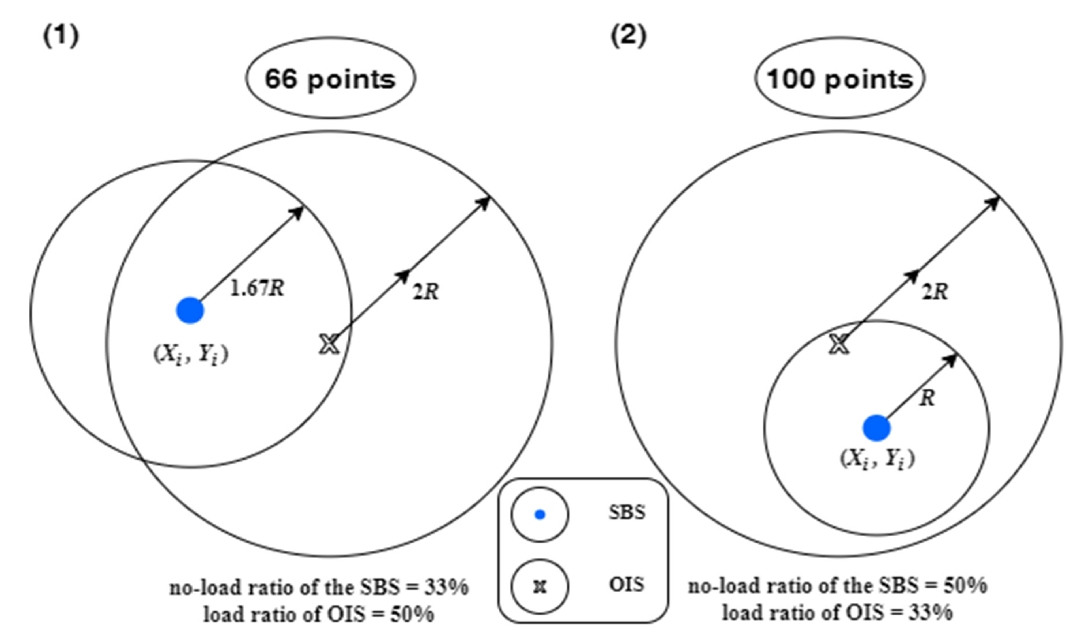
When the OIS determines that ϕ i ψ , this indicates that SBS i can fully handle the OIS’s load, at which point s c o r e load is 100. When the OIS determines that ϕ i < ψ , this indicates that SBS i can only handle a part of the OIS’s load, at which point s c o r e load is calculated based on the above formula. If SBS i is at full load, it would be considered unsuitable for a handover, at which point s c o r e load is 0. Figure 14 illustrates two scenarios as follows: (1) SBS i cannot fully handle the OIS’s load; and (2) SBS i can fully handle the OIS’s load. In Scenario 1, ϕ i < ψ ; hence, s c o r e load = 33 % 50 % × 100 = 66; and in Scenario 2, ϕ i ψ ; hence, s c o r e load = 100.
(4)
Total score after weight averaging ( s c o r e total )
After the scoring system has scored all of the SBSs in SBSG1 according to the three-stage scoring process described above, the scores for each stage are weight-averaged to calculate the total score s c o r e total . If the score for any stage is 0 or if SBSG1 is an empty set (i.e., there is no signal coverage), s c o r e total = 0. Therefore, s c o r e total can be expressed as
s c o r e total = { k hold s c o r e hold + k RSSmax s c o r e RSSmax + k load s c o r e load , s c o r e hold 0 ,   s c o r e RSSmax 0 ,   s c o r e load 0 0 , otherwise ,  
where k hold ( 0 k hold 1 ), k RSSmax ( 0 k RSSmax 1 ), and k load ( 0 k load 1 ) are the weights for s c o r e hold , s c o r e RSSmax , and s c o r e load , respectively, and k hold + k RSSmax + k load = 1 .
As the final step, we rank the SBSs in SBSG1 according to their respective s c o r e total , and the highest-scoring SBS is logged. In the event of a tie in the scores, random ranking is performed. If all of the scores are 0, the overload support mechanism is activated to support the OIS.

3.4. Overload Support Mechanism

To simplify subsequent descriptions, the set of ASBSs that can transmit to and receive from any of SBSG1’s SBSs is defined as SBSG2, as shown in Figure 15. If all the SBSs in SBSG1 are unable to provide any service to OIS (that is, s c o r e total is 0 for all SBSs in SBSG1), the ASBSs of SBSG2 are then switched to super, with the purpose of (1) distributing the load of SBSG1’s SBSs in a manner that enables them to provide service to the OIS or (2) enabling the ASBSs to directly provide service to the OIS.
After switching these ASBSs to super mode, we then determine the load that each ASBS can undertake based on their no-load ratio (i.e., ϕ i ,   i SBSG 2 ). The calculation method considers the degree to which each ASBS can share the load of the SBSG1 SBS that is closer to the OIS and identifies the ASBS that can best handle the load. If SBSG1 is an empty set, the ASBSs of SBSG2 that can provide service to the OIS are added to SBSG1.
After fully executing the overload support mechanism, the updated SBS sizes and mode status information then form the basis for the next round of calculations.

3.5. Handover Stage

In the final handover stage, the focus is on the timing of handovers. We defined RSS th , i as the RSS threshold of SBS i and used it as a basis for determining the handover timing in a specific range. It can be expressed as
RSS th , i = 20 log P TX K K th d i ,  
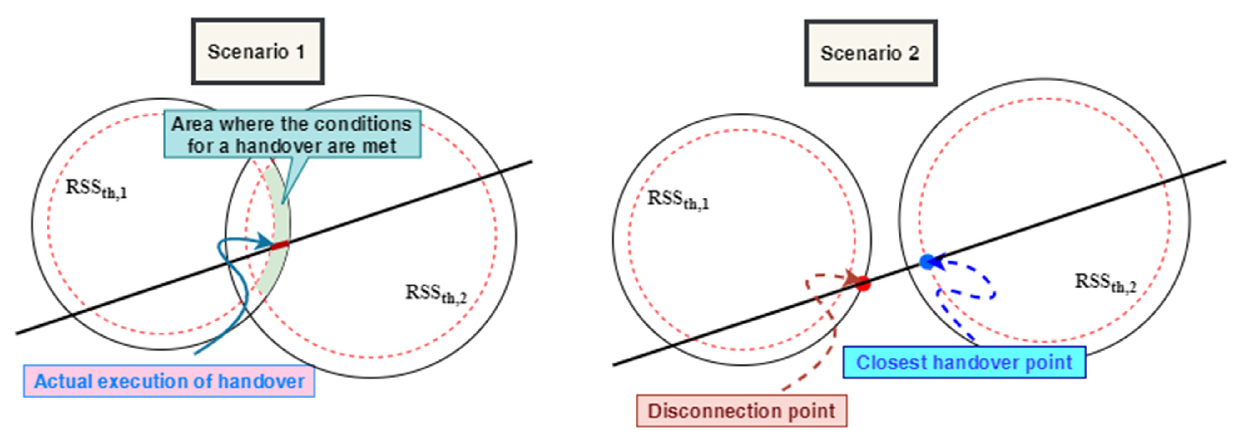
where K th is the threshold constant, which has a value between 0 and 1. We defined RSS th , 1 and RSS th , 2 , respectively, as the RSS threshold of the SBS currently connected to the OIS and the RSS threshold of the SBS selected through the scoring mechanism. These two thresholds are calculated using (31). If RSS is less than RSS th , 1 , the next step is to determine if RSS is greater than RSS th , 2 with a handover being executed if this is true; otherwise, the operation would continue until the conditions are met at which point a handover would be executed.
Figure 16 illustrates the two scenarios that could occur based on the intersecting relationship between the coverage of the SBS currently connected to the OIS and the SBS selected through the scoring mechanism (areas outlined with the black solid lines), as well as the intersecting relationship between their threshold coverage (areas outlined with red dashed lines). Scenario 1: the coverage of the two thresholds overlap; in which case, the handover is executed in the overlapping area. Scenario 2: the coverage of the two thresholds do not overlap; in which case, the OIS disconnects from the currently connected SBS when it leaves this SBS’s coverage and executes a handover when it enters the threshold coverage of the selected SBS.
After the handover is completed, the five stages are repeated until the OIS is shut down.

3.6. Time Complexity Analysis

Specifically, let N denote the number of cars that make up a train. The worst-case performance of the toss-and-catch algorithm, with time complexity being a function of | | , | MSBS | , | non - MSBS | , |SBSG1|, and N, is provided as follows. The dominant operation costs for each OIS (recall that each car contains a single OIS) include the following: (1) SBS categorization, where the time taken for c1 | | + c2 | non - MSBS | | MSBS | + c3 | non - MSBS | is used to perform comparisons, and c1, c2, and c3 are constants; (2) the sorting of scores by the score-based selection mechanism, where time complexity is O(|SBSG1|log|SBSG1|). As such, for the train as a whole, the worst-case time complexity of the algorithm is O(N ( | | + | non - MSBS | | MSBS | + | non - MSBS | +|SBSG1|log |SBSG1|)). Note that the value of N is usually not large, being approximately 10 in most cases. Taking THSR as an example, the observed N value is 12. Furthermore, given the kernel range’s efficient design and the realistic scenarios for the deployment of SBSs, | | is typically more than 10 but unlikely to exceed 100 (also note that SBSG1 ). Therefore, this level of complexity should be acceptable in a typical scenario.

3.7. Pros and Cons

As shown in the preceding analysis, the toss-and-catch algorithm is an efficient algorithm when applied to the overall system. The pros and cons of the algorithm are summarized in Table 1.

4. Simulation Results and Discussion

As the OIS in each car of a train operates independently and uses the same toss-and-catch algorithm, the statistical data generated by a single car should be virtually identical to those generated by multiple cars if a long-term observation is performed. To facilitate our simulation, we only considered the case of a train with one car, that is, only one OIS is in operation, and simulated the proposed algorithm’s performance using Matlab. In order to produce more realistic simulations, this study also performed simulations of fading in different channel environments by employing Nakagami-q fading channels in which q = 3, 1, and 1/2 [26,27]. This was done with the aim of developing SBS selection and handover methods that are more practical for mobile terminal equipment in the future. Note that since a channel is influenced by the degree of fading, d i in (2) changes accordingly as well.
The performance items that were tested include the following: (1) connection hold rate: the ratio of the communication connection time between the OIS and SBSs to the train’s total travel time; (2) handover frequency: frequency of OIS handovers (total number of handovers/total travel time); (3) average RSS: OIS’s average RSS in relation to total travel time; and (4) manageable load percentage of the OIS: percentage of OIS’s load that the SBSs can handle. Train speed and OIS’s load ratio were designated as the variables for testing these four performance items.
We demonstrated the advantages of the proposed method by conducting a comparison involving two control groups:
(1)
Control Group 1: Unlike the proposed method, the method applied to this group did not incorporate SBS categorization and the overload support mechanism and adjusted the mode of each SBS according to the SBS’s load ratio. Note that the worst-case time complexity of Control Group 1 is O(N( | | +|SBSG1|log |SBSG1|)).
(2)
Control Group 2: This group is identical to Control Group 1 in all ways except that it uses a random selection mechanism instead of a score-based one. Note that the worst-case time complexity of Control Group 2 is O(N | | ).
Although the levels of time complexity of these two control groups are lower than that of the toss-and-catch algorithm, the analysis in Section 3.6 has shown that the toss-and-catch algorithm’s complexity level remains acceptable in a typical scenario. The complete and detailed simulation results that are subsequently obtained show that, compared to the two control groups, the toss-and-catch algorithm enables superior performance for the four performance items of interest discussed above and only at the slight expense of time complexity. This superior performance is particularly pronounced with respect to the connection hold rate and manageable load percentage of the OIS.

4.1. Simulation Method and Parameter Design

To facilitate the simulation, while the train is moving, SBSs are deployed within the kernel (10 × 10 square grid with an actual geographic area measuring 10 2 R × 10 2 R m2) ranges that the OIS generates whenever it does so. It is randomly determined whether an SBS is deployed in a 1 × 1 grid. Since the SBS boot preset radius is R, we deployed SBSs in the center of a 1 × 1 grid, such that the grids with deployed SBSs are within the signal coverage range. Concurrently, for each kernel range, we also generated the slope m and constant b of the track equation that approximates the actual track path. Figure 17 illustrates a track path as well as the deployed SBSs and their statuses within the kernel at t n . When the OIS leaves its current kernel range, the above steps are repeated.
A train speed range of 0–603 km/hr is assumed [28] for this study. In order to measure train speed more accurately during our simulations, we used a dashboard to obtain the train’s speed at t n and denoted it as v GPS t n . Following that, we used the coordinate system conversion framework to obtain the corresponding speed v t n in the kernel coordinate system. v t n can be expressed as
v t n = v GPS t n × 1000 3600 × 1 2 R .  
To produce more realistic simulations, the random bursts of acceleration were applied based on v t n . Specifically, with the initial train speed 0 km/hr, we designed the train to perform positive variable acceleration (denoted as a up t n ) from v GPS t n = 0 km/hr to v GPS t n = 603 km/hr; and upon reaching its maximum speed, the train then performed negative variable acceleration (denoted as a down t n ) from v GPS t n = 603 km/hr to v GPS t n = 0 km/hr. a up t n and a down t n were defined as follows:
a up t n = { random ( 0 , 0.100 ) , 0 v t n < 0.1964   ( 0 v GPS t n < 200 ) random ( 0 , 0.050 ) , 0.1964 v t n < 0.3928   ( 200 v GPS t n < 400 ) random ( 0 , 0.040 ) , 0.3928 v t n < 0.5402   ( 400 v GPS t n < 550 ) random ( 0 , 0.033 ) , 0.5402 v t n 0.5922   ( 550 v GPS t n 603 ) ,  
a down t n = { - random ( 0 , 0.100 ) , 0 v t n < 0.1964   ( 0 v GPS t n < 200 ) - random ( 0 , 0.050 ) , 0.1964 v t n < 0.3928   ( 200 v GPS t n < 400 ) - random ( 0 , 0.040 ) , 0.3928 v t n < 0.5402   ( 400 v GPS t n < 550 ) - random ( 0 , 0.033 ) , 0.5402 v t n 0.5922   ( 550 v GPS t n 603 ) .  
When performing the simulations, we set G TX = 100, G RX = 100, λ = 0.01 m, and L = 1 in RSS formula (22). In addition, we also set R = 200 m, which is approximately the preset coverage range of a picocell. Since picocells have been shown to have a P TX of 0.26 W when their coverage radius is 400 m [10], RSS = −99.8757 dBm when the OIS is 400 m away from the emission center of a picocell, which also indicates the minimum RSS value allowed when demodulating a signal. The following settings were also used: K th = 0.95, k hold = 1/3, k RSSmax = 1/3, and k load = 1/3.
From a practical perspective, the time taken for the entire handover procedure can be divided into the selection and handover phases: (1) The time taken to complete the selection process: the time taken for the central processing unit (CPU) to calculate and determine a suitable SBS for a handover, and (2) the time taken to complete the handover process: the time taken to complete the handover procedure with the selected SBS. In our simulations, it takes a train about 4.1362 s to pass through an MSBS on average (the trains moved at a speed of about 301.5 km/h, and the path length through each MSBS was about 346.41 m). According to the simulations, the CPU took about 500 ms to complete the selection process; and as highlighted in an aforementioned study [2], the time taken to complete a handover is negligible if the fixed track pre-handover authentication scheme proposed in that study is implemented. In other words, the entire process can be completed in approximately 500 ms, making it a feasible solution when considering that a train stays in the range of an MSBS for about 4.1362 s.

4.2. Effects of the OIS’s Speed on Various Aspects of Performance

4.2.1. Connection Hold Rate

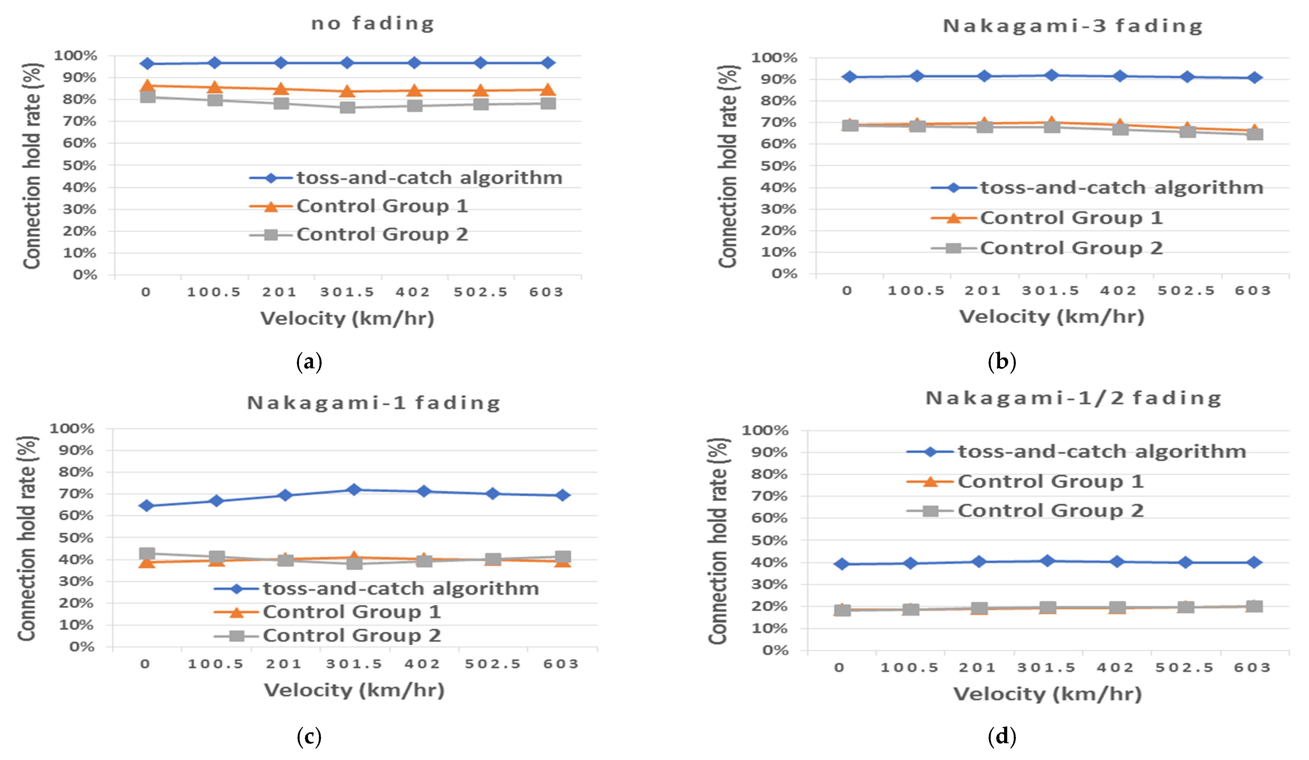
Figure 18 shows the performance of the OIS’s connection hold rate in relation to its speed in various channel environments. Figure 18a shows that when there is no fading in the channel (only the path loss is considered), the toss-and-catch algorithm performed better than Control Groups 1 and 2 at all OIS velocities. In the toss-and-catch algorithm, the SBSs are categorized into MSBSs, ASBSs, and OSBSs, and the super mode was applied to the MSBSs. Therefore, after the score-based selection mechanism has made a selection, the connection score of the MSBSs is increased. In addition, if the OIS fails to identify a suitable MSBS for a handover, the overload support mechanism assists to increase the overall connection hold rate of a moving train.
We further explored the performance of these three methods in various fading conditions. According to the results presented in Figure 18b–d, the toss-and-catch algorithm performed better than Control Groups 1 and 2, regardless of the fading condition employed. Even though the channel was affected by Nakagami-3 fading such that the track coverage of the SBSs was slightly smaller than that in a nonfading environment, most of the track paths can still be covered. In other words, even though the performance of all three methods had decreased slightly, the degree of decline was not substantial. When Nakagami-1 fading is employed, the degree of fading is greater than that when Nakagami-3 fading is employed and the effective signal coverage of the SBSs is only able to cover fewer track paths. Therefore, when comparing Figure 18b,c, it can be seen that the performance of the two control groups had decreased by around 30%, while the performance of the toss-and-catch algorithm had decreased by around 20%. When Nakagami-1/2 fading is employed, the fading of the channel environment was so severe that the effective signal coverage area of the SBSs was practically unable to cover the track paths. Therefore, under this condition, the connection hold rate is below 50% for all three methods, which signifies that the OIS is disconnected half the time when the train is moving. However, compared to Control Groups 1 and 2, the toss-and-catch algorithm had a better ability to reduce the impacts brought by the harsh environment, and its connection hold rate was even two times higher those of the two control groups. This superiority could be due to the fact that the MSBSs’ mode configuration was set to super mode and the ASBSs were used to assist the overload support mechanism to increase the connection performance of the OIS. Hence, the toss-and-catch algorithm had a better performance than the two control groups.

4.2.2. Handover Frequency

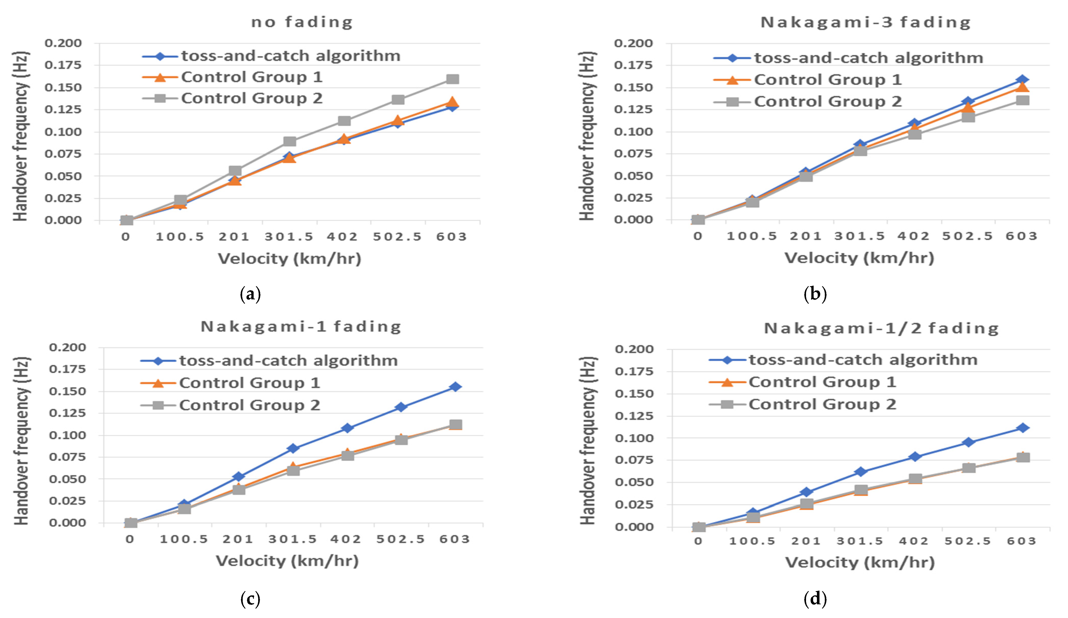
Figure 19 shows the performance of the OIS’s handover frequency in relation to its speed in various channel environments. According to Figure 19a–d, in all three methods, the handover frequency increased in response to increasing velocities. This is because under higher velocities, the OIS quickly leaves the effective coverage area of each selected SBS, and the handover frequency increases as a result. In nonfading environments, the handover frequencies of the toss-and-catch algorithm and Control Group 1 were significantly lower than those of Control Group 2. This is because the toss-and-catch algorithm and Control Group 1 are assisted by the score-based selection mechanism and are able to select more suitable SBSs; meanwhile, when the channel is not affected by fading effects, the SBSs have a large effective signal coverage area, and the OIS has more SBS options.
When Nakagami-3 fading is employed, the channel was affected by slight fading, and the effective signal coverage area was slightly reduced, but the effects on the handover frequencies of all three methods were not substantial. Specifically, the handover frequencies of the toss-and-catch algorithm and Control Group 1 had increased slightly, while those of Control Group 2 had decreased slightly. For instance, in comparison with Figure 19a, the handover frequencies of the toss-and-catch algorithm and Control Group 1 increased slightly by 0.025 Hz, while those of Control Group 2 decreased by 0.050 Hz. From a theoretical perspective, the handover frequency should increase when each SBS effective signal coverage area that the OIS passes through becomes smaller. However, for Control Group 2, the OIS was less able to identify a suitable SBS for a handover and was disconnected, thus reducing the handover frequency. When Nakagami-1 fading is employed, the toss-and-catch algorithm has marginal changes in terms of handover frequency, whereas those of the two control groups have declined significantly (for example, at a train speed of 603 km/hr, and in comparison with Figure 19b, the handover frequencies of Control Groups 1 and 2 had decreased by 0.038 and 0.024 Hz, respectively). The reason for this decline is the same as when Nakagami-3 fading is employed: that is, the greater fading effects had reduced the handover abilities of the control groups and ultimately resulted in disconnection. When Nakagami-1/2 fading is employed, severe channel fading had reduced the handover frequencies of all three methods, which indicates that there were more disconnections. For example, at a train speed of 603 km/hr, the handover frequencies of all three methods were about 0.035 Hz lower compared to the frequencies presented in Figure 19c. This is because when the effects of fading are more significant, the number of deployed SBSs is insufficient for all three methods.

4.2.3. Average RSS

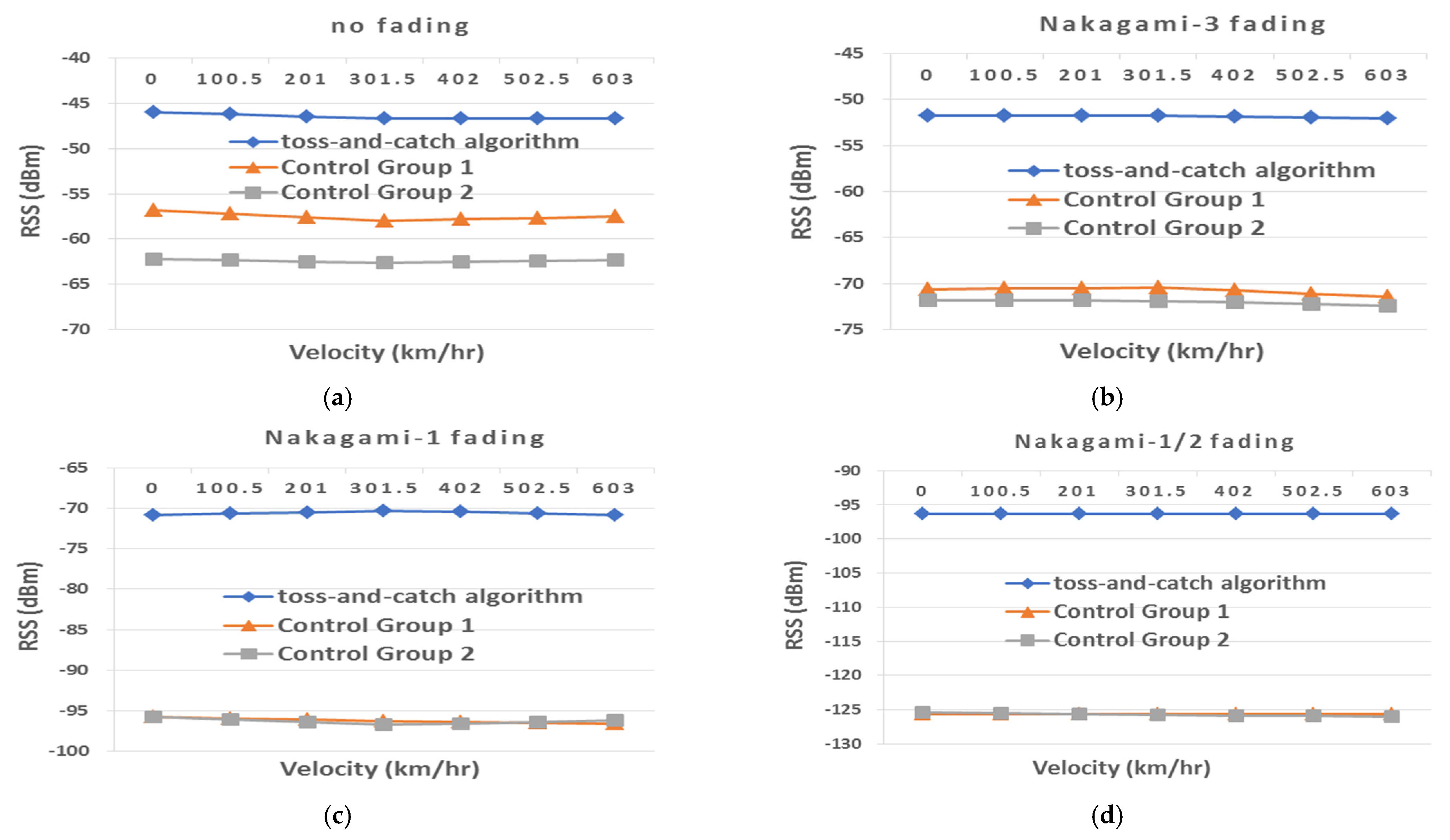
Figure 20 shows the performance of the OIS’s average RSS in relation to its speed in various channel environments. In nonfading environments, the toss-and-catch algorithm has a better average RSS than the two control groups at various velocities. On average (in terms of the average RSSs of various velocities), the performance of the toss-and-catch algorithm is about 15 dB higher than that of Control Group 2. This is due to the fact that the super mode was applied to the MSBSs, in addition to the assistance of the overload support mechanism of the ASBSs. Therefore, the SBSs selected by the moving train had a larger average effective signal coverage area and thus a higher average RSS.
As shown in Figure 20b–d, in all fading environments, the toss-and-catch algorithm performed better than the two control groups. As the fading became more severe, while the performance of all three methods declined, the performance of the toss-and-catch algorithm became significantly better than those of the control groups. This is because the effective signal coverage area of the SBS selected by the OIS becomes smaller in response to the increasing severity of fading, and the OIS has a higher chance of selecting an SBS that offers less RSS. Moreover, since the super mode was not established in the SBSs of both control groups, both groups were less able to cover the track paths, which resulted in a significantly lower average RSS performance compared to the toss-and-catch algorithm. Specifically, when Nakagami-3 fading is employed, the performance of the toss-and-catch algorithm decreased by about 5 dB in comparison with nonfading environments, while the performance of Control Groups 1 and 2 decreased by about 13 dB and about 10 dB, respectively. The reason for this is as follows: after the OIS using the toss-and-catch algorithm is connected to a suitable SBS through the score-based selection mechanism and overload support mechanism, it is able to select an SBS that offers more RSS (it has a higher chance of receiving a stronger signal), and as a result, the decline in the average RSS is relatively low. When Nakagami-1 fading is employed, the performance of the toss-and-catch algorithm was about 18 dB lower than that in Nakagami-3 fading channel environments, while those of the control groups decreased by about 24 dB. Therefore, it is evident that even though the OIS’s decline in average RSS caused by channel fading would further decrease in all three methods, the level of decline of the toss-and-catch algorithm is relatively lower. Furthermore, when Nakagami-1/2 fading is employed, the difference between the performance of the toss-and-catch algorithm and the control groups is significantly larger. For example, at a train speed of 301.5 km/hr, Figure 20c,d show that the performance of Control Group 1 is, respectively, about 26 dB and about 29 dB lower than that of the toss-and-catch algorithm.

4.2.4. Manageable Load Percentage of the OIS

Figure 21 shows the performance of the manageable load percentage of the OIS in relation to its speed in various channel environments. According to Figure 21a, in all three methods, the manageable load percentage of the OIS decreases in response to increasing train speed. This is because the chances of disconnection increase with increasing train speed. Nonetheless, the toss-and-catch algorithm performed better than the control groups at various train speeds, as its connection hold rate is higher than the control groups. Therefore, when a train is moving, there are more chances for the SBSs to continuously handle the OIS’s load, and generally speaking, there are more OIS loads that can be handled by the SBSs. In addition, we can see that at low- and medium-speed intervals, the SBSs selected by the toss-and-catch algorithm are capable of handling over 90% of the OIS’s load. This is mainly because the OIS has a longer retention time for the selected SBSs and there are fewer chances of signal disconnection. Moreover, since the toss-and-catch algorithm is designed to select SBSs effectively, it has a better load-handling capacity.
When Nakagami-3 fading is employed, the toss-and-catch algorithm still produces a decent performance, while the performance of both control groups declined significantly. In the case of Nakagami-1 fading and Nakagami-1/2 fading, as shown in Figure 21c,d, respectively, the performance of Control Groups 1 and 2 are both below 50%. This effect is particularly pronounced when Nakagami-1/2 fading is employed, as the performance of both control groups were only half of that of the toss-and-catch algorithm in most conditions. This can be explained by the better performance of the toss-and-catch algorithm in terms of SBS selection and MSBS mode adjustment, made possible with the assistance of the overload support mechanism in which the ASBSs may undertake the loads of MSBSs that are closer to the OIS.

4.3. Effects of the OIS’s Load Ratio on Various Aspects of Performance

4.3.1. Connection Hold Rate

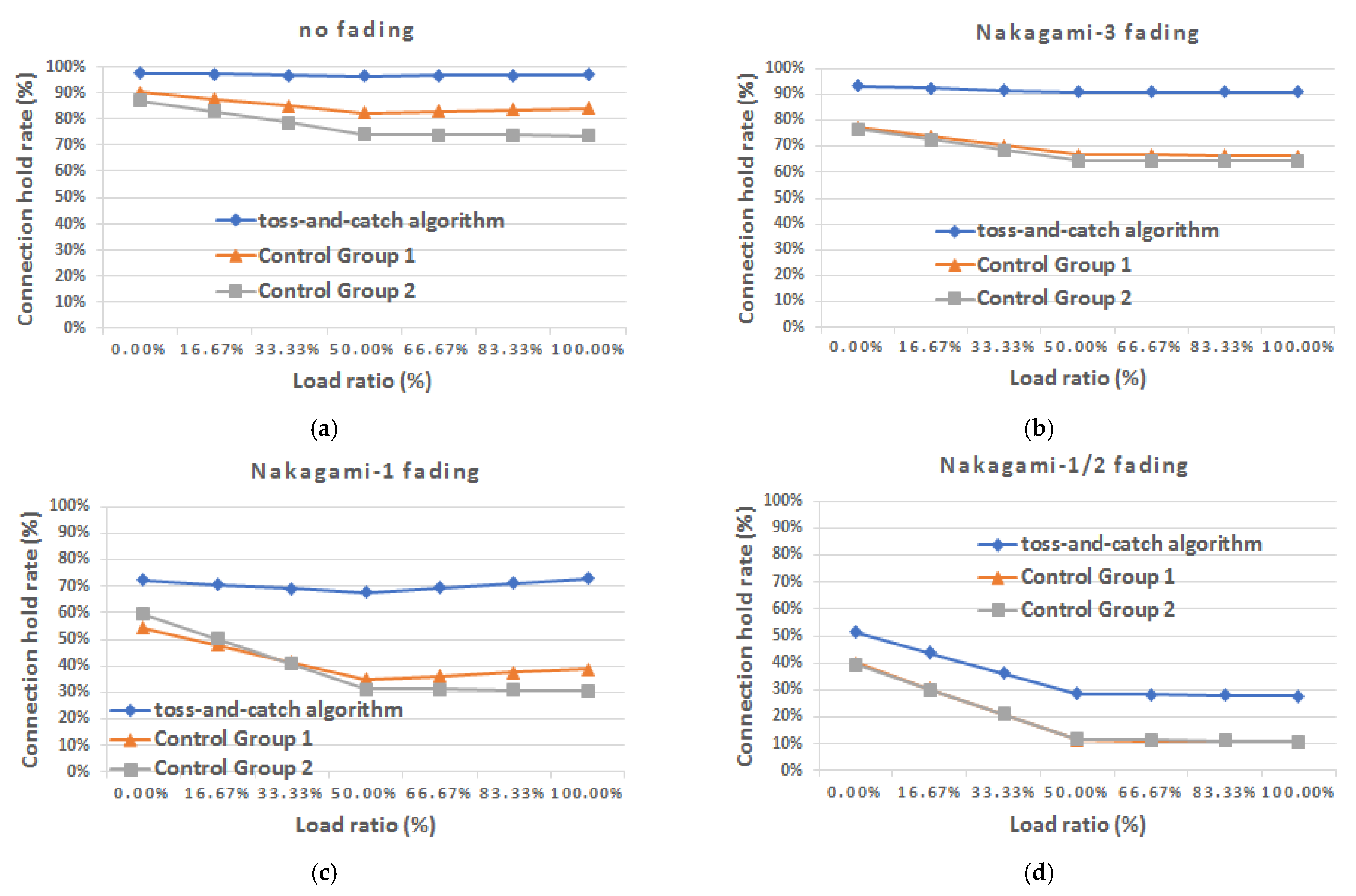
Figure 22 shows the performance of the OIS’s connection hold rate in relation to its load ratio in various channel environments. It can be seen from Figure 22a that when no fading is employed, the toss-and-catch algorithm performed better than Control Groups 1 and 2 at all OIS load ratios. This is because the OIS of the toss-and-catch algorithm has a higher chance of selecting SBSs (which are mostly MSBSs) with a larger coverage radius, and effective assistance is provided by the overload support mechanism; hence, performance is practically unaffected. Moreover, according to Figure 22a, for Control Group 1, when the OIS load ratio is smaller than or equal to 50%, the connection hold rate declines gradually and slightly in response to increasing OIS load ratios. This can be explained by the score-based selection mechanism, as the OIS has a higher chance of selecting SBSs with a smaller coverage radius and there are gradually less suitable SBS options. On the other hand, when the load ratio of the OIS exceeds 50%, Control Group 1 has a higher chance of selecting SBSs with a larger coverage radius, and there are gradually more SBS options (in comparison with the SBS options when the load ratio of the OIS is equal to 50%), which slightly increases the connection hold rate.
In all fading conditions, as seen in Figure 22b–d, the toss-and-catch algorithm also performed better than Control Groups 1 and 2. When Nakagami-3 fading is employed, the degree of fading is marginal, and the toss-and-catch algorithm is practically unaffected, while the performance of both control groups declined significantly by around 10%. This is because the two control groups lacked an overload support mechanism, and there were fewer SBS options, which reduced the chances of the OIS to continuously select an SBS that can undertake its load and thereby decreased the connection hold rate. When Nakagami-1 fading is employed, the degree of fading and its effects increased, thus reducing the assistance provided by the overload support mechanism to the toss-and-catch algorithm and resulting in a marked decline in the connection hold rate. On the other hand, the OISs of the two control groups had even fewer SBS options compared to the toss-and-catch algorithm, and the coverage area was even smaller. Therefore, the two control groups had more significant declines in their connection hold rates in comparison with the toss-and-catch algorithm. For example, as shown in Figure 22c, when the OIS load ratio is 50%, the connection hold rate of the toss-and-catch algorithm decreases by around 20%, while the rates of the two control groups decreases by around 30%. When Nakagami-1/2 fading is employed, severe fading had occurred in the channels, which largely reduced all three methods’ effective signal coverage of the track paths, and hence, the connection hold rates decreased significantly. This is because under this fading condition, there were very few SBS options for the OISs of all three methods, and the overload support mechanism of the toss-and-catch algorithm had no effect whatsoever. Nevertheless, the connection hold rate of the toss-and-catch algorithm remained two times higher than those of the two control groups, which can be attributed to the fact that the MSBSs of the former were in super mode and the SBSs were selected through the score-based selection mechanism. Therefore, the toss-and-catch algorithm still performed better than the two control groups.

4.3.2. Handover Frequency

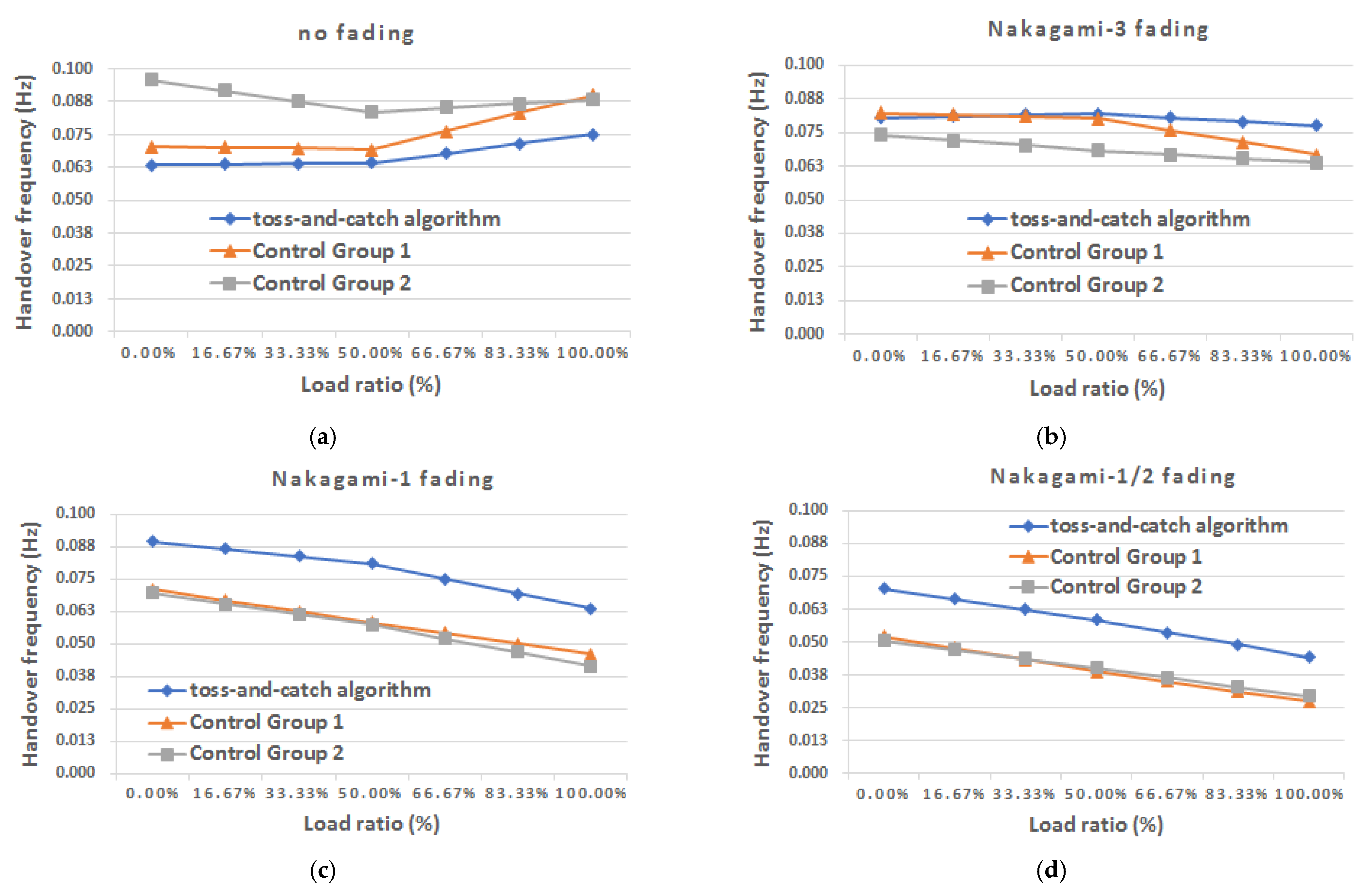
Figure 23 shows the performance of the OIS’s handover frequency in relation to its load ratio in various channel environments. In nonfading environments, as shown in Figure 23, the handover frequency of the toss-and-catch algorithm is lower than those of the two control groups, as the algorithm is more capable of identifying more suitable SBSs. Control Group 2 has a higher handover frequency as its OIS lacked the score-based selection mechanism.
According to Figure 23b–d, in all three methods, the handover frequencies declined in response to increasing OIS load ratios in most conditions. This is because under higher OIS load ratios, there are fewer SBS options, and the handover frequencies decreased as a result. When Nakagami-3 fading is employed, the overall effective signal coverage area of the SBSs is slightly smaller due to the slight fading effects. As a result, there are slightly fewer SBS options for this OIS. In this environment, the toss-and-catch algorithm has a slightly higher handover frequency compared to the control groups, as its OIS has more chances to perform handovers with suitable SBSs and prevent disconnections. When Nakagami-1 fading is employed and when the OIS load ratio exceeds 50%, the handover frequencies for all three methods declined, particularly those of Control Groups 1 and 2. This is because the toss-and-catch algorithm had a better ability than Control Groups 1 and 2 in identifying suitable SBSs for communication. For example, at an OIS load ratio of 100% and in comparison with Figure 23b, the handover frequencies of the toss-and-catch algorithm and Control Group 1 had decreased by 0.014 Hz, while those of Control Groups 1 and 2 had decreased by 0.021 Hz and 0.022 Hz, respectively. When Nakagami-1/2 fading is employed, the handover frequencies for all three methods further decreased by around 0.020 Hz (in comparison with Figure 23c), which indicates that there were more disconnections. This is because in such fading environments, the number of SBSs deployed is unable to handle the OIS load. In other words, when the channel environment is harsh to the point that there are no options available, more SBSs should be deployed in order to overcome this problem. At this point, the process is controlled by the number of SBSs deployed.

4.3.3. Average RSS

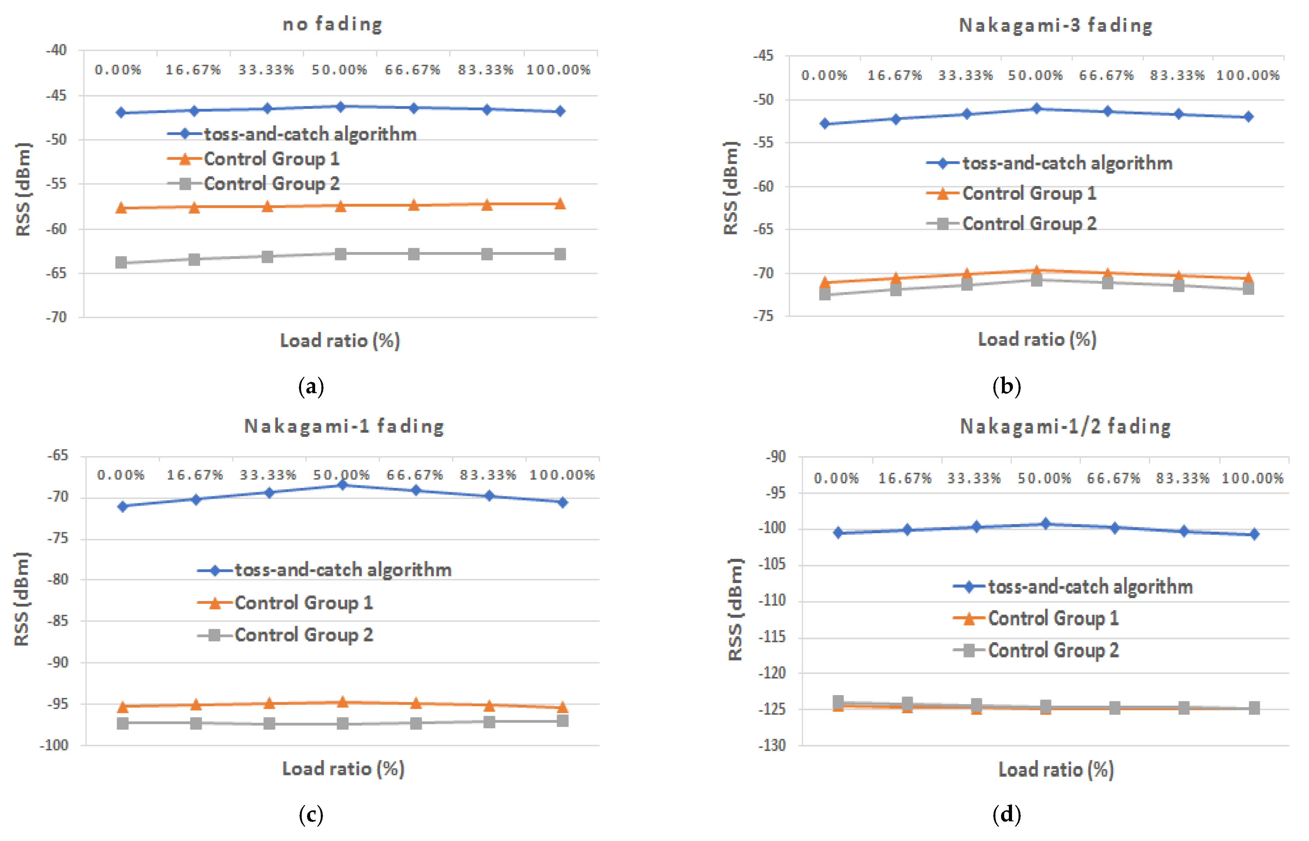
Figure 24 shows the performance of the OIS’s average RSS in relation to its load ratio in various channel environments. Regardless of the presence of fading effects in the channels, the toss-and-catch algorithm has a better average RSS than the two control groups at various OIS load ratios. For example, when the load ratio of the OIS is 50% and there are no fading effects in the channel, as shown in Figure 24a, the performances of Control Groups 1 and 2 were about 11 dB and about 17 dB lower, respectively, than that of the toss-and-catch algorithm. When Nakagami-3 fading is employed, the performances of Control Groups 1 and 2 were about 19 dB and about 20 dB lower, respectively, than that of the toss-and-catch algorithm; when Nakagami-1 fading is employed, the performances of Control Groups 1 and 2 were about 27 dB and about 29 dB lower, respectively, than that of the toss-and-catch algorithm; when Nakagami-1/2 fading is employed, the performances of Control Groups 1 and 2 were both about 26 dB lower than that of the toss-and-catch algorithm. All of the aforementioned outcomes are due to the lack of an effective design in both control groups, which resulted in a relatively lower average RSS. Therefore, when the level of fading increases, the control groups are less able to resist the impacts such that the declines in average RSS become more significant and even to the point of disconnection (according to the findings in Section 4.1, a signal cannot be demodulated when the RSS is lower than −99.8757 dBm).
With regard to the toss-and-catch algorithm, when the load ratio of the OIS is between 0% and 50%, the performance of the algorithm in terms of average RSS increases in response to an increasing load ratio; whereas when the load ratio is between 50% and 100%, the performance of the algorithm decreases in response to an increasing load ratio. In the former, when the load ratio of the OIS increases, there are more chances for activating the overload support mechanism in which the ASBSs can undertake the loads of MSBSs that are closer to the OIS. Consequently, the OIS has a higher chance of selecting these MSBSs, thereby increasing its average RSS. In the latter, when the load ratio of the OIS increases, the overload support capacity of the ASBSs is gradually full, and the average RSS decreases slightly. Nevertheless, compared to the two control groups that lack an ASBS overload support mechanism, the performance of the toss-and-catch algorithm remains significantly better.

4.3.4. Manageable Load Percentage of the OIS

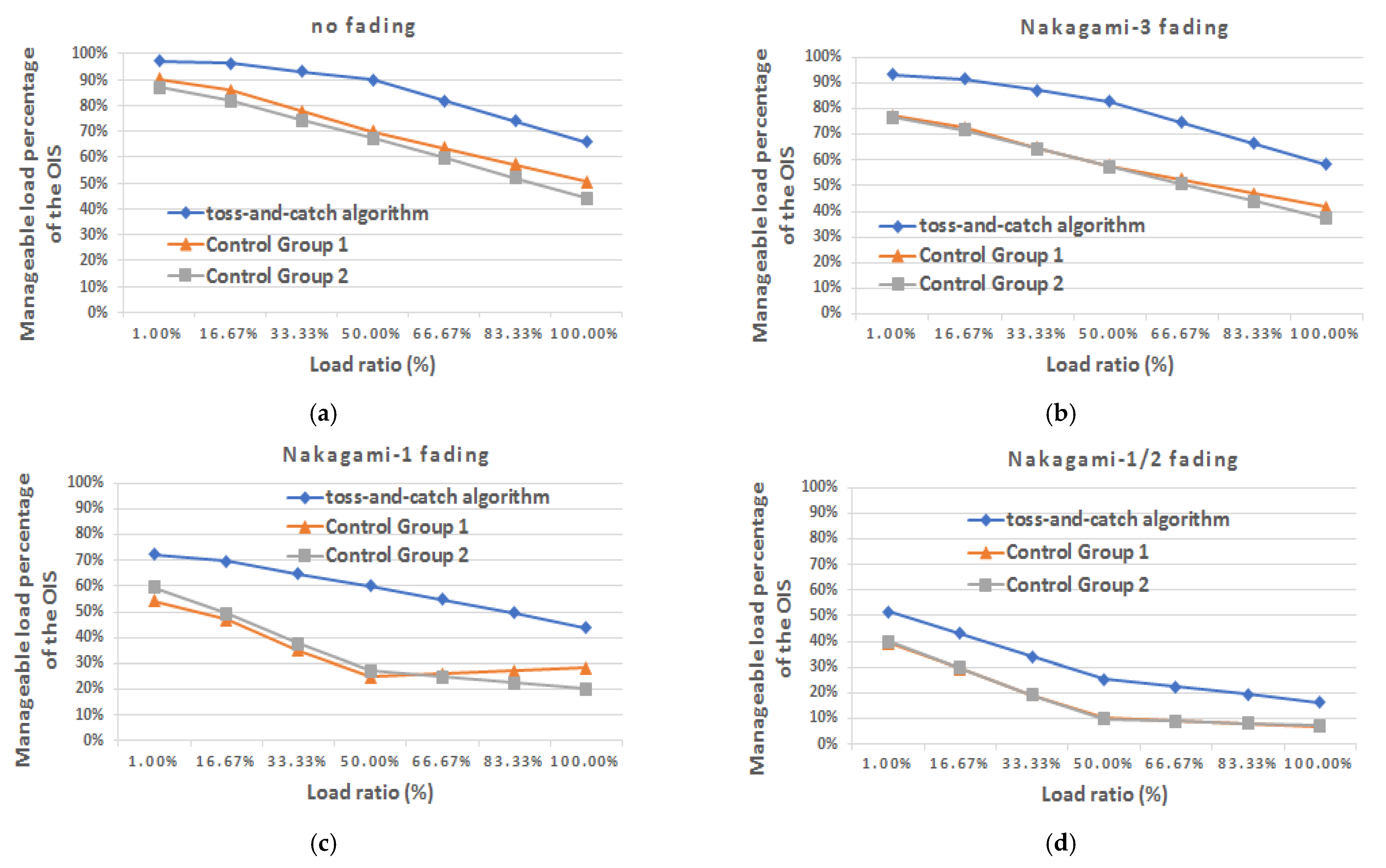
Figure 25 shows the performance of the manageable load percentage of the OIS in relation to its load ratio in various channel environments. When there is no channel fading, in all three methods, the manageable load percentage of the OIS decreases in response to increasing load ratio. This is because the load capacity that can be handled by each SBS is independent of the OIS’s load ratio, and hence, an SBS would not exceed its upper load-handling limit even under high OIS load ratios. Moreover, we also observe that the toss-and-catch algorithm has the best performance among the three methods. This is because the toss-and-catch algorithm has a higher connection hold rate than the control groups and has a higher chance of selecting a suitable SBS, which in turn offers more chances of continuously handling the OIS’s loads. Therefore, the toss-and-catch algorithm performed better than the two other methods at various OIS load ratios. In addition, we found that at an OIS load ratio smaller than or equal to 50%, the SBSs selected by the toss-and-catch algorithm are capable of handling over 90% of the OIS’s load, mainly because the loads under such conditions are mostly within the load range that most of the SBSs are fully capable of handling.
When Nakagami-3 fading is employed, the load-handling capacities of the SBSs selected by the toss-and-catch algorithm performed decently, whereas those of the two control groups declined significantly. When Nakagami-1 fading is employed, under most load ratios, the load-handling capacities of the SBSs selected by the toss-and-catch algorithm have exceeded 50% (at an OIS load ratio range of 1% to 83.33%), whereas those of the control groups are lower than 50% (at an OIS load ratio range of 16.67% to 100%). When Nakagami-1/2 fading is employed, the performances of all three methods are below 50% (nonetheless, the performance of the toss-and-catch algorithm was 10% higher than the two control groups in most conditions). This is because the severe fading had reduced the number of SBSs that can be selected by the OIS, as well as the connection hold rate, which lowered the OIS’s overall total manageable load percentage.

5. Conclusions and Future Work

This study successfully developed an algorithm that incorporates multidimensional design features such as kernel coordinate conversion, SBS mode setting and coverage area scaling configuration, GPS positioning, a score-based selection mechanism, an overload support mechanism, and handover threshold values. The algorithm was named the toss-and-catch algorithm and can be applied to the OISs of fixed-rail transportation for effective handover selection. First, kernel coordinate conversion, SBS mode setting and coverage area scaling configuration, and GPS positioning designs were implemented so that the toss-and-catch algorithm could provide assistance to the OIS based on its requirements whenever appropriate and the SBSs could provide service to the OIS, thereby allowing the algorithm to maintain its basic level of performance advantage when facing various environmental changes. Next, the toss-and-catch algorithm performed SBS scoring and sorting, provided assistance through the overload support mechanism (which is activated if necessary), and underwent handover threshold settings, thus allowing it to identify the most suitable SBS for a handover based on the OIS’s requirements.
We demonstrated the superiority of the toss-and-catch algorithm through ample simulations of its performance in terms of connection hold rate, handover frequency, average RSS, and manageable load percentage of the OIS. The simulation results showed that, in most scenarios, the toss-and-catch algorithm outperformed other traditional methods in a nonfading environment and various types of symmetric fading channel environments. In specific terms, the simulation results showed that by using the toss-and-catch algorithm, the OIS has more SBS options for a handover (as reflected through its handover frequency), and the OIS can intelligently select a suitable SBS at the appropriate time, thus significantly increasing the algorithm’s performance in terms of connection hold rate and average RSS. An increase in the algorithm’s connection hold rate is beneficial for enhancing the data volume that can be continuously handled while the OIS is moving (as reflected through the manageable load percentage of the OIS). Meanwhile, an increase in the algorithm’s average RSS is, in practice, beneficial for improving the service quality for users. Therefore, we believe that in the future, the toss-and-catch algorithm can be applied to the multitude of fixed-rail mobile terminal equipment of various communication systems for effective handover and connection.
Considering the fact that the toss-and-catch algorithm can be systematically implemented in our daily lives, we provide some suggestions for functional enhancements or applications based on the algorithm. First, if we could design a database that records the SBSs that the OIS passes by on a daily basis as well as the statistical data of the algorithm’s performance assessment, then regions with high user demand and those that lack coverage can be logged into the database as well. The database can then be provided free or as an equal value and interest exchange solution for network service providers to implement prioritized deployment. Through this approach, network service providers can accurately deploy SBSs in regions with higher user demand as well as identify regions that lack coverage but have demand. Next, the data in the database should be accumulated so that the network service providers can continue with SBS deployment. The data can also be used in the activation of time-sensitive Internet of things (IoT) software or devices as well as the establishment of the algorithm on fixed-rail transportation, such that the SBSs selected by the toss-and-catch algorithm for a handover can ensure the normal operation of these time-sensitive application programs or equipment while a train is moving. Lastly, we hope that the toss-and-catch algorithm can be applied to the Internet of vehicles (IoV) of general vehicles for pre-handover SBS selection. Even though general vehicles have a lower maximum speed compared to fixed-rail public transportation systems, the uncertainty of the operating tracks would increase the difficulty of analysis. Therefore, if the track path (including the turns and unfixed tracks) of a vehicle can be predetermined, then the toss-and-catch algorithm can serve as a basis for the development of another algorithm or the modification of the existing algorithm, which also takes into account non-fixed-rail-based IoT devices. Going forward, the toss-and-catch algorithm (or a modified version of it) and artificial intelligence (AI) application could be further integrated and applied to emerging IoV technologies (e.g., the application of AI-based object detection to detect highway accidents [29]). This would enable us to take the integration of the two emerging fields of 5G IoV and AI to the next level.

Author Contributions

Conceptualization, Y.-L.C. and S.-H.W.; methodology, Y.-L.C. and S.-H.W.; software, S.-H.W.; validation, Y.-L.C.; formal analysis, Y.-L.C.; investigation, Y.-L.C. and S.-H.W.; data curation, Y.-L.C. and S.-H.W.; writing—original draft preparation, Y.-L.C.; writing—review and editing, Y.-L.C.; visualization, S.-H.W.; supervision, Y.-L.C. All authors have read and agreed to the published version of the manuscript.

Funding

This research received no external funding.

Acknowledgments

The authors wish to express their appreciation for the financial support provided by the Ministry of Science and Technology (MOST) of Taiwan, R.O.C., under Contract MOST 109-2221-E-019 -051-MY2.

Conflicts of Interest

The authors declare no conflict of interest.

Appendix A. Conversion of the Actual Geographic Coordinate System to the Kernel Coordinate System
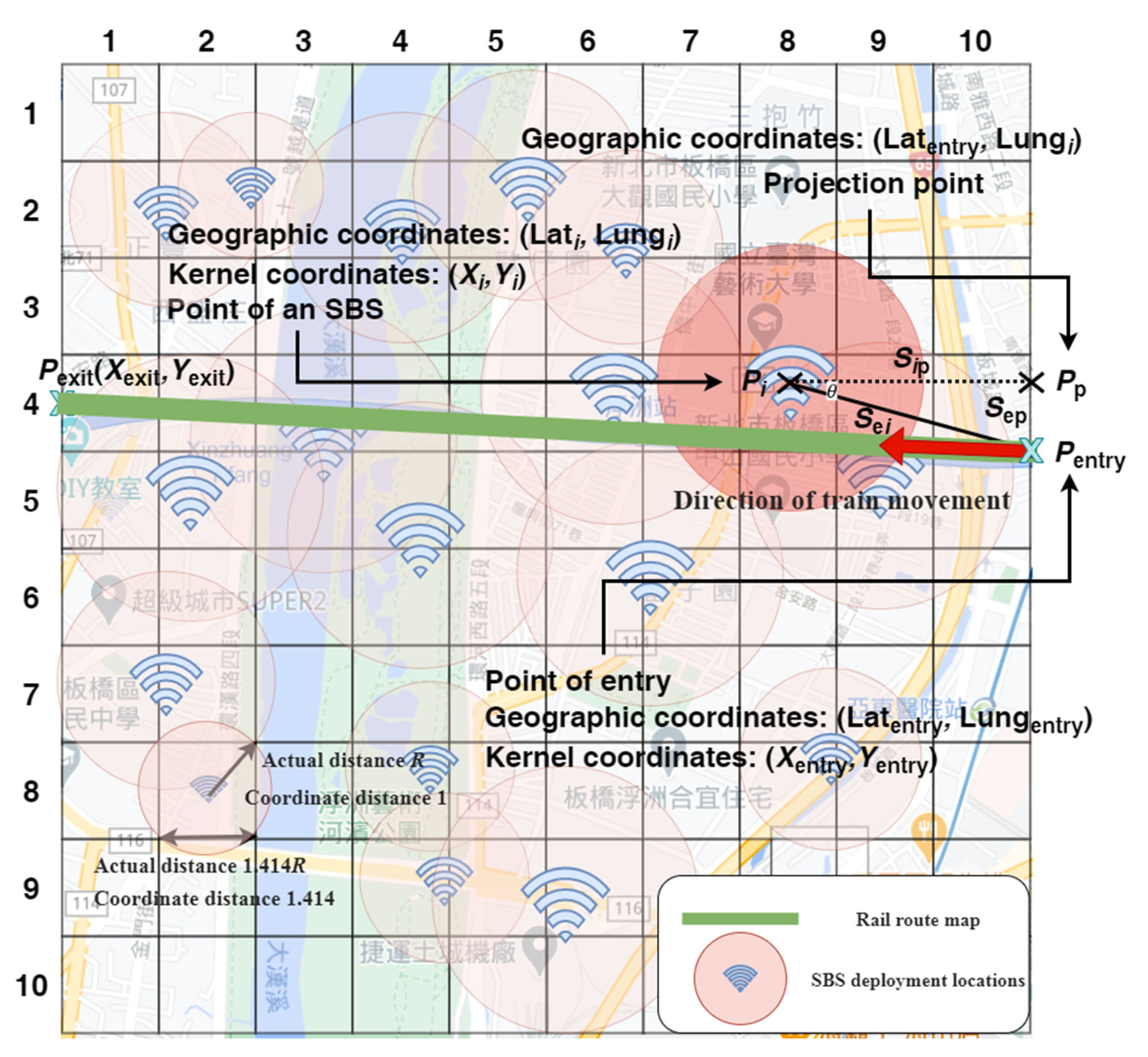
Assuming that the geographic coordinates of two points obtained through GPS are ( Lat A , Lung A ) and ( Lat B , Lung B ) , respectively, then (A1) can be used to calculate the distance S between the two points [30]
S = 2 sin 1 sin 2 ( a 2 ) + cos ( Lat 1 ) × cos ( Lat 2 ) × sin 2 ( b 2 ) × 6371 × 10 3   ( m ) ,
where a = Lat A Lat B and b = Lung A Lung B .
As shown in Figure A1, when a train enters a kernel, assume that the geographic coordinates of the starting point are P entry = ( Lat entry , Lung entry ) and the geographic coordinates of an SBS are P i = ( Lat i , Lung i ) . Projecting the path obtained by connecting points P entry and P i onto the right-hand side boundary of the kernel would yield P p = ( Lat entry , Lung i ) . Let S e i , S ep , and S i p represent, respectively, the actual geographic distance between P entry and P i , the actual geographic distance between P entry and P p , and the actual geographic distance between P i and P p . Then, S e i , S ep , and S i p can be derived from (A1). Let S e i , kernel represent the length of S e i after kernel coordinate conversion. As defined earlier in Figure 4, the relationship between the unit coordinate length of a kernel and its actual geographic length is one coordinate unit: 2 R m. Therefore, S e i , kernel can be expressed as
S e i , kernel = S e i 2 R .  
Let θ represent the angle between the path of the line connecting P entry and P i and the path of the line connecting P i and P p , which is given by
θ = tan 1 S ep S i p .  
As was defined earlier, ( X entry , Y entry ) represents the kernel coordinates of the starting point when a train enters the kernel. The kernel coordinates of the SBS ( X i , Y i ) can be expressed as
X i = X entry + S e i , kernel cos θ ,  
Y i = Y entry + S e i , kernel sin θ .  
The coordinates of any SBS on the kernel can be derived through the preceding equations (i.e., (A1)–(A5)).
Figure A1. Converting actual geographic coordinates into kernel coordinates.
Symmetry 13 00582 g0a1

References

  1. Small Cell Forum. Available online: http://www.smallcellforum.org (accessed on 12 March 2021).
  2. Ma, R.; Cao, J.; Feng, D.; Li, H.; He, S. FTGPHA: Fixed-Trajectory Group Pre-Handover Authentication Mechanism for Mobile Relays in 5G High-Speed Rail Networks. IEEE Trans. Veh. Technol. 2020, 69, 2126–2140. [Google Scholar] [CrossRef]
  3. Panigrahy, N.K.; Ghosh, S.C. Analyzing the Effect of Soft Handover on Handover Performance Evaluation Metrics under Load Condition. IEEE Trans. Veh. Technol. 2018, 67, 3612–3624. [Google Scholar] [CrossRef]
  4. Pan, M.; Lin, T.; Chen, W. An Enhanced Handover Scheme for Mobile Relays in LTE-A High-Speed Rail Networks. IEEE Trans. Veh. Technol. 2015, 64, 743–756. [Google Scholar] [CrossRef]
  5. Cheng, M.; Fang, X.; Luo, W. Beamforming and Positioning-Assisted Handover Scheme for Long-Term Evolution System in High-Speed Railway. IET Commun. 2012, 6, 2335–2340. [Google Scholar] [CrossRef] [Green Version]
  6. Achroufene, A.; Amirat, Y.; Chibani, A. RSS-Based Indoor Localization Using Belief Function Theory. IEEE Trans. Autom. Sci. Eng. 2019, 16, 1163–1180. [Google Scholar] [CrossRef]
  7. Zanella, A.; Bardella, A. RSS-Based Ranging by Multichannel RSS Averaging. IEEE Wireless Commun. Lett. 2014, 3, 10–13. [Google Scholar] [CrossRef]
  8. Li, J.; Gao, J.; Zhang, H.; Qiu, T.Z. RSE-Assisted Lane-Level Positioning Method for a Connected Vehicle Environment. IEEE Trans. Intell. Transp. Syst. 2019, 20, 2644–2656. [Google Scholar] [CrossRef]
  9. Duong, T.M.; Kwon, S. Vertical Handover Analysis for Randomly Deployed Small Cells in Heterogeneous Networks. IEEE Trans. Wirel. Commun. 2020, 19, 2282–2292. [Google Scholar] [CrossRef]
  10. Auer, G.; Giannini, V.; Desset, C.; Godor, I.; Skillermark, P.; Olsson, M.; Imran, M.A.; Sabella, D.; Gonzalez, M.J.; Blume, O.; et al. How Much Energy Is Needed to Run a Wireless Network? IEEE Wirel. Commun. 2011, 18, 40–49. [Google Scholar] [CrossRef]
  11. Aleksic, S.; Deruyck, M.; Vereecken, W.; Joseph, W.; Pickavet, M.; Martens, L. Energy Efficiency of Femtocell Deployment in Combined Wireless/Optical Access Networks. Comput. Netw. 2013, 57, 1217–1233. [Google Scholar] [CrossRef] [Green Version]
  12. Huang, L.; Zhou, Y.; Wang, Y.; Han, X.; Shi, J.; Chen, X. Advanced Coverage Optimization Techniques for Small Cell Clusters. China Commun. 2015, 12, 111–122. [Google Scholar] [CrossRef]
  13. Wang, Y.; Dai, X.; Wang, J.M.; Bensaou, B. Iterative Greedy Algorithms for Energy Efficient LTE Small Cell Networks. In Proceedings of the 2016 IEEE Wireless Communications and Networking Conference, Doha, Qatar, 3–6 April 2016. [Google Scholar]
  14. Chung, Y.-L. Energy-Saving Transmission for Green Macrocell—Small Cell Systems: A System-Level Perspective. IEEE Syst. J. 2017, 11, 706–716. [Google Scholar] [CrossRef]
  15. Chung, Y.-L. An Energy-Efficient Coverage Algorithm for Macrocell—Small Cell Network Systems. Energies 2017, 10, 1319. [Google Scholar] [CrossRef] [Green Version]
  16. Lu, Y.; Xiong, K.; Fan, P.; Zhong, Z.; Ai, B. The Effect of Power Adjustment on Handover in High-Speed Railway Communication Networks. IEEE Access 2017, 5, 26237–26250. [Google Scholar] [CrossRef]
  17. Xu, X.; Yuan, C.; Chen, W.; Tao, X.; Sun, Y. Adaptive Cell Zooming and Sleeping for Green Heterogeneous Ultradense Networks. IEEE Trans. Veh. Technol. 2018, 67, 1612–1621. [Google Scholar] [CrossRef]
  18. Xie, L.; Heegaard, P.E.; Jiang, Y. Survivability Analysis of a Two-Tier Infrastructure-Based Wireless Network. Comput. Netw. 2017, 128, 28–40. [Google Scholar] [CrossRef] [Green Version]
  19. Pons, X.; Mesodiakaki, A.; Gruet, C.; Naviner, L.; Adelantado, F.; Alonso, L.; Verikoukis, C. An Energy Efficient Vertical Handover Decision Algorithm. In Proceedings of the 2014 IEEE Global Communications Conference Workshops 2nd Workshop on Green Broadband Access: Energy Efficient Wireless and Wired Network Solutions, Austin, TX, USA, 8–12 December 2014. [Google Scholar]
  20. Catak, E.; Moldsvor, A.; Derawi, M. Transceiver Design for GFDM with Hexagonal Time–Frequency Allocation Using the Polyphase Decomposition. Electronics 2020, 9, 1862. [Google Scholar] [CrossRef]
  21. Ma, Y.-W.; Chen, J.-L.; Lin, C.-J. Automated Network Load Balancing and Capacity Enhancing Mechanism in Future Network. IEEE Access 2018, 6, 19407–19418. [Google Scholar] [CrossRef]
  22. Aqeeli, E.; Moubayed, A.; Shami, A. Dynamic SON-Enabled Location Management in LTE Networks. IEEE Trans. Mob. Comput. 2018, 17, 1511–1523. [Google Scholar] [CrossRef]
  23. Qin, M.; Yang, Q.; Cheng, N.; Li, J.; Wu, W.; Rao, R.R.; Shen, X. Learning-Aided Multiple Time-Scale SON Function Coordination in Ultra-Dense Small-Cell Networks. IEEE Trans. Wirel. Commun. 2019, 18, 2080–2092. [Google Scholar] [CrossRef]
  24. Stewart, J. Calculus: Early Transcendentals, 6th ed.; Brooks/Cole Cengage Learning: Boston, MA, USA, 2008. [Google Scholar]
  25. Rappaport, T.S. Wireless Communications Principles & Practice, 2nd ed.; Prentice Hall Inc.: Upper Saddle River, NJ, USA, 2002. [Google Scholar]
  26. Nakagami, M. The m-distribution—A general formula of intensity distribution of rapid fading. In Statistical Methods of Radio Wave Propagation; Hoffman, W.C., Ed.; Pergamon Press: Elmsford, NY, USA, 1960; pp. 3–36. [Google Scholar]
  27. Chung, Y.-L.; Tsai, Z. Performance Analysis of Two Multichannel Fast Retransmission Schemes for Delay-Sensitive Flows. IEEE Trans. Veh. Technol. 2010, 59, 3468–3479. [Google Scholar] [CrossRef]
  28. Phys.org. 603 km/h: Japan’s Maglev Train Breaks New World Speed Record (Update 2). Available online: https://phys.org/news/2015-04-kmh-japan-maglev-notches-world.html (accessed on 17 February 2021).
  29. Chung, Y.-L.; Lin, C.-K. Application of a Model that Combines the YOLOv3 Object Detection Algorithm and Canny Edge Detection Algorithm to Detect Highway Accidents. Symmetry 2020, 12, 1875. [Google Scholar] [CrossRef]
  30. Haversine Formula. Available online: https://en.wikipedia.org/wiki/Haversine_formula (accessed on 28 October 2020).
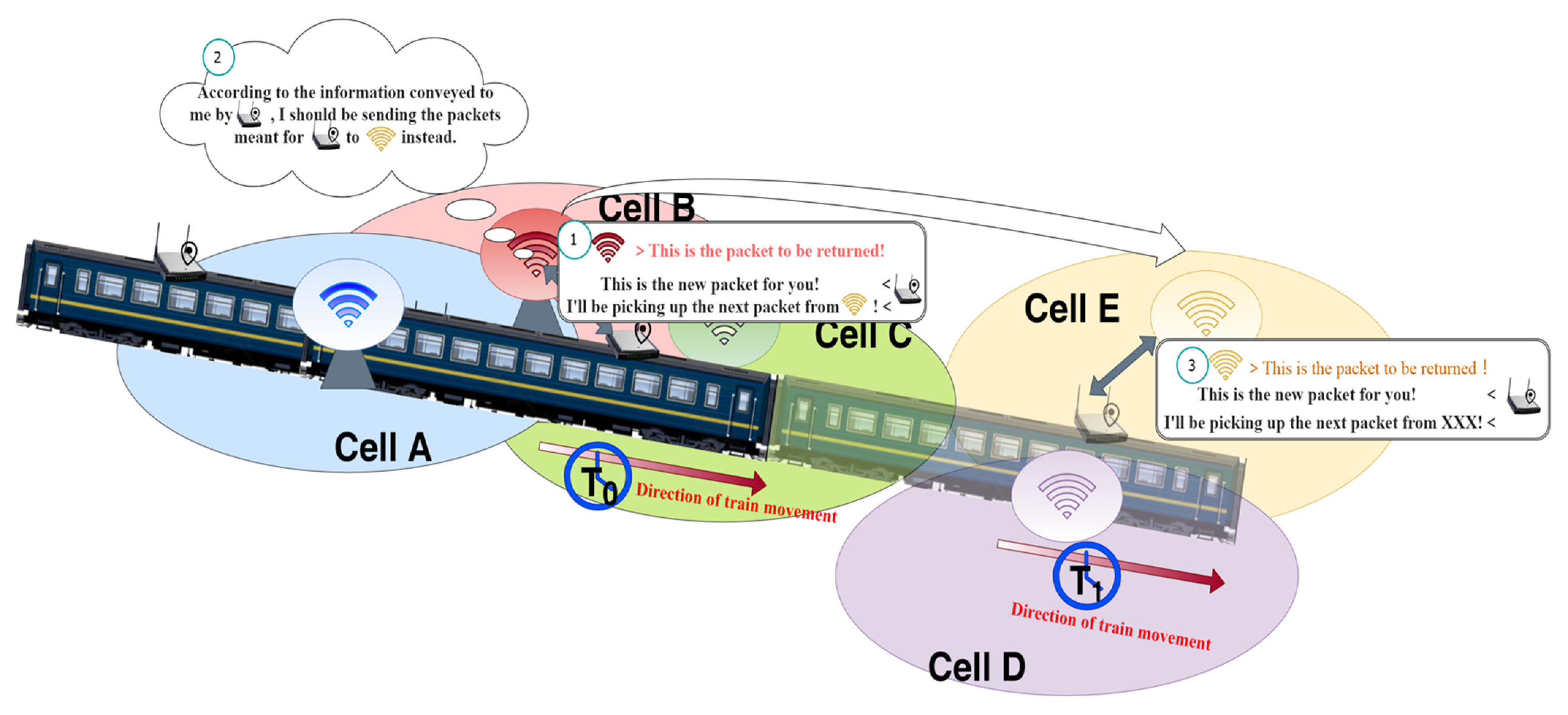
Figure 1. Toss-and-catch algorithm concept (as illustrated by the ① –> ② –> ③ sequence of conversations). At T0, the “outdoor unit (ODU) + indoor unit (IDU) + small cell” (OIS) is communicating with Cell B and uses the toss-and-catch algorithm (detailed description in Section 3) to determine that it will enter the coverage of Cell E at T1; the OIS then informs Cell B to transfer the returning transmission data to Cell E, with the result that the OIS can receive returning transmission data from Cell E at T1.
Symmetry 13 00582 g001
Figure 2. Scenario diagram.
Symmetry 13 00582 g002
Figure 3. Flowchart of the proposed toss-and-catch algorithm.
Symmetry 13 00582 g003
Figure 4. Kernel coordinate system model.
Symmetry 13 00582 g004
Figure 5. Schematic diagram showing the kernel block selection range in relation to the actual geographic region.
Symmetry 13 00582 g005
Figure 6. Schematic diagram showing four scenarios in which the OIS uses a kernel to select the track range, with Scenarios 1 and 2 being invalid selections and Scenarios 3 and 4 being valid selections.
Symmetry 13 00582 g006
Figure 7. Identification of main small cell base stations (MSBSs).
Symmetry 13 00582 g007
Figure 8. Identification of auxiliary small cell base stations (ASBSs) and other small cell base stations (OSBSs).
Symmetry 13 00582 g008
Figure 9. Determination of small cell base station (SBS) for handover by the OIS.
Symmetry 13 00582 g009
Figure 10. Diagram showing SBSG1.
Symmetry 13 00582 g010
Figure 11. Geometric relationship between the track equation and the SBS currently being scored.
Symmetry 13 00582 g011
Figure 12. Calculation of s c o r e hold .
Symmetry 13 00582 g012
Figure 13. Calculation of s c o r e RSSmax .
Symmetry 13 00582 g013
Figure 14. Calculation of s c o r e load .
Symmetry 13 00582 g014
Figure 15. Diagram showing SBSG2.
Symmetry 13 00582 g015
Figure 16. Handover scenarios (the areas enclosed by black solid lines represent the SBSs’ coverage; the areas enclosed by the red dashed lines represent their threshold coverage).
Symmetry 13 00582 g016
Figure 17. Diagram showing the track path and the deployed SBSs and their statuses within the kernel at t n ; the straight line indicates the track path and “x” indicates the center of an SBS (its coverage range varies depending on its load ratio).
Symmetry 13 00582 g017
Figure 18. Comparing the performance of the OIS’s connection hold rate in relation to its speed using the three methods in (a) nonfading environments; (b) Nakagami-3 fading environments; (c) Nakagami-1 fading environments; and (d) Nakagami-1/2 fading environments.
Symmetry 13 00582 g018
Figure 19. Comparing the performance of the OIS’s handover frequency in relation to its speed using the three methods in (a) nonfading environments; (b) Nakagami-3 fading environments; (c) Nakagami-1 fading environments; and (d) Nakagami-1/2 fading environments.
Symmetry 13 00582 g019
Figure 20. Comparing the performance of the OIS’s average received signal strength (RSS) in relation to its speed using the three methods in (a) nonfading environments; (b) Nakagami-3 fading environments; (c) Nakagami-1 fading environments; and (d) Nakagami-1/2 fading environments.
Symmetry 13 00582 g020
Figure 21. Comparing the performance of the manageable load percentage of the OIS in relation to its speed using the three methods in (a) nonfading environments; (b) Nakagami-3 fading environments; (c) Nakagami-1 fading environments; and (d) Nakagami-1/2 fading environments.
Symmetry 13 00582 g021
Figure 22. Comparing the performance of the OIS’s connection hold rate in relation to its load ratio using the three methods in (a) nonfading environments; (b) Nakagami-3 fading environments; (c) Nakagami-1 fading environments; and (d) Nakagami-1/2 fading environments.
Symmetry 13 00582 g022
Figure 23. Comparing the performance of the OIS’s handover frequency in relation to its load ratio using the three methods in (a) nonfading environments; (b) Nakagami-3 fading environments; (c) Nakagami-1 fading environments; and (d) Nakagami-1/2 fading environments.
Symmetry 13 00582 g023
Figure 24. Comparing the performance of the OIS’s average RSS in relation to its load ratio using the three methods in (a) nonfading environments; (b) Nakagami-3 fading environments; (c) Nakagami-1 fading environments; and (d) Nakagami-1/2 fading environments.
Symmetry 13 00582 g024
Figure 25. Comparing the effects of the OIS’s manageable load percentage on its load ratio using the three methods in (a) nonfading environments; (b) Nakagami-3 fading environments; (c) Nakagami-1 fading environments; and (d) Nakagami-1/2 fading environments (the OIS load ratio was set to begin at 1.00%, as there was no point in examining an OIS load ratio of 0% for this experiment).
Symmetry 13 00582 g025
Table 1. Overview of the pros and cons of the toss-and-catch algorithm.
ProsCons
  • Combines designs derived from multiple viewpoints to create an effective algorithm that optimizes handover selection
  • Does not consider different sets of quality-of-service requirements
  • When the OIS has multiple SBS options, unnecessary handovers can be avoided, which helps improve overall communication quality.
  • Does not consider interference issues 1
  • Adapts well to changes in channel environments
  • Applicable to all types of fixed-rail transportation
  • Ensures reliable transmission
  • Ensures non-interruptible handovers
  • Serves as a good base for developing or integrating various emerging information and communication technology applications
1 This research focuses on the application of the pre-handover concept as well as the integration of designs derived from multiple viewpoints to preselect suitable SBSs and thereby improve post-handover performance. Although interference is an important concern when SBSs are densely deployed, we have considered recent developments in wireless communication technology and assumed that appropriate mechanisms have been implemented at the physical layer to address or mitigate the impact of potential interference.
Publisher’s Note: MDPI stays neutral with regard to jurisdictional claims in published maps and institutional affiliations.