
Analysis of Asymmetrical Deformation of Surface and Oblique Pipeline Caused by Shield Tunneling along Curved Section


Abstract
:1. Introduction
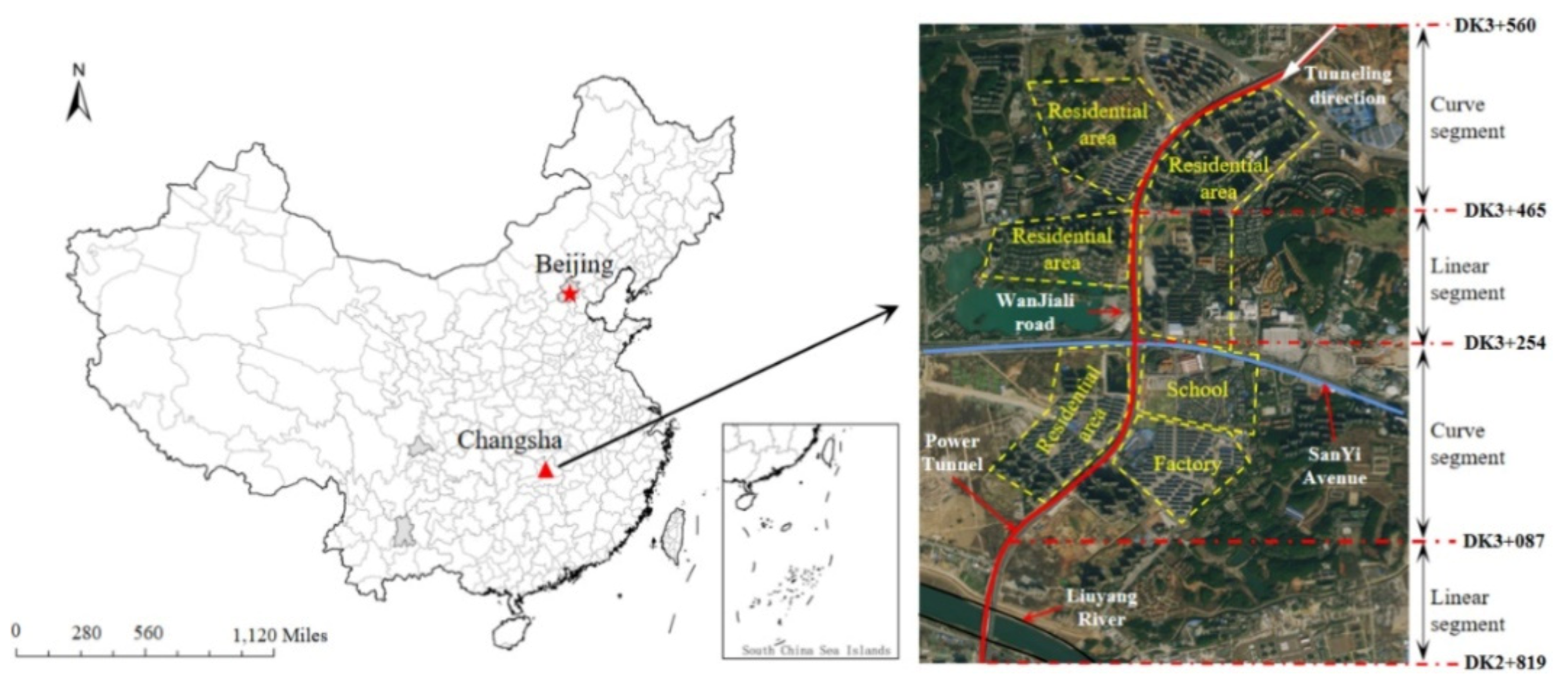
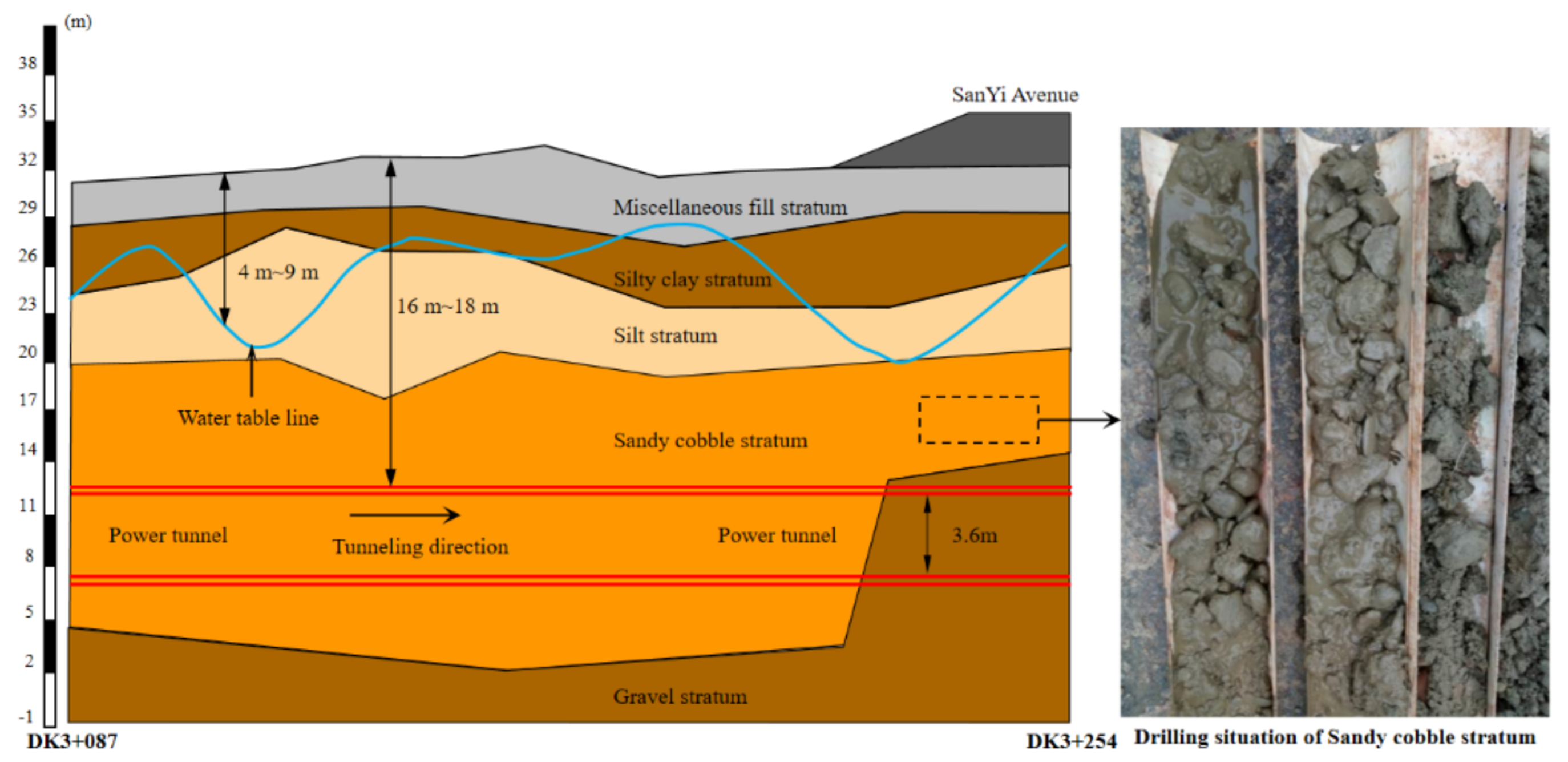
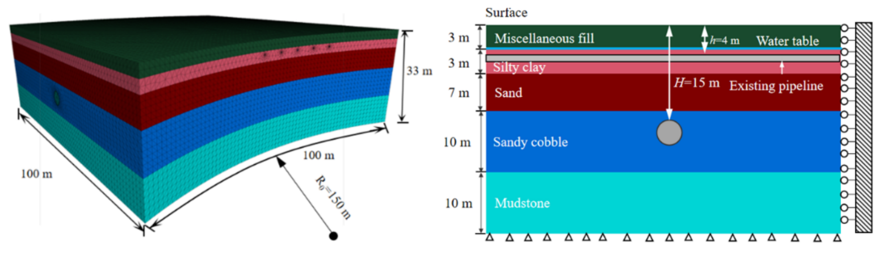
2. Project Overview
3. Calculation Methods of Pipeline Deformation
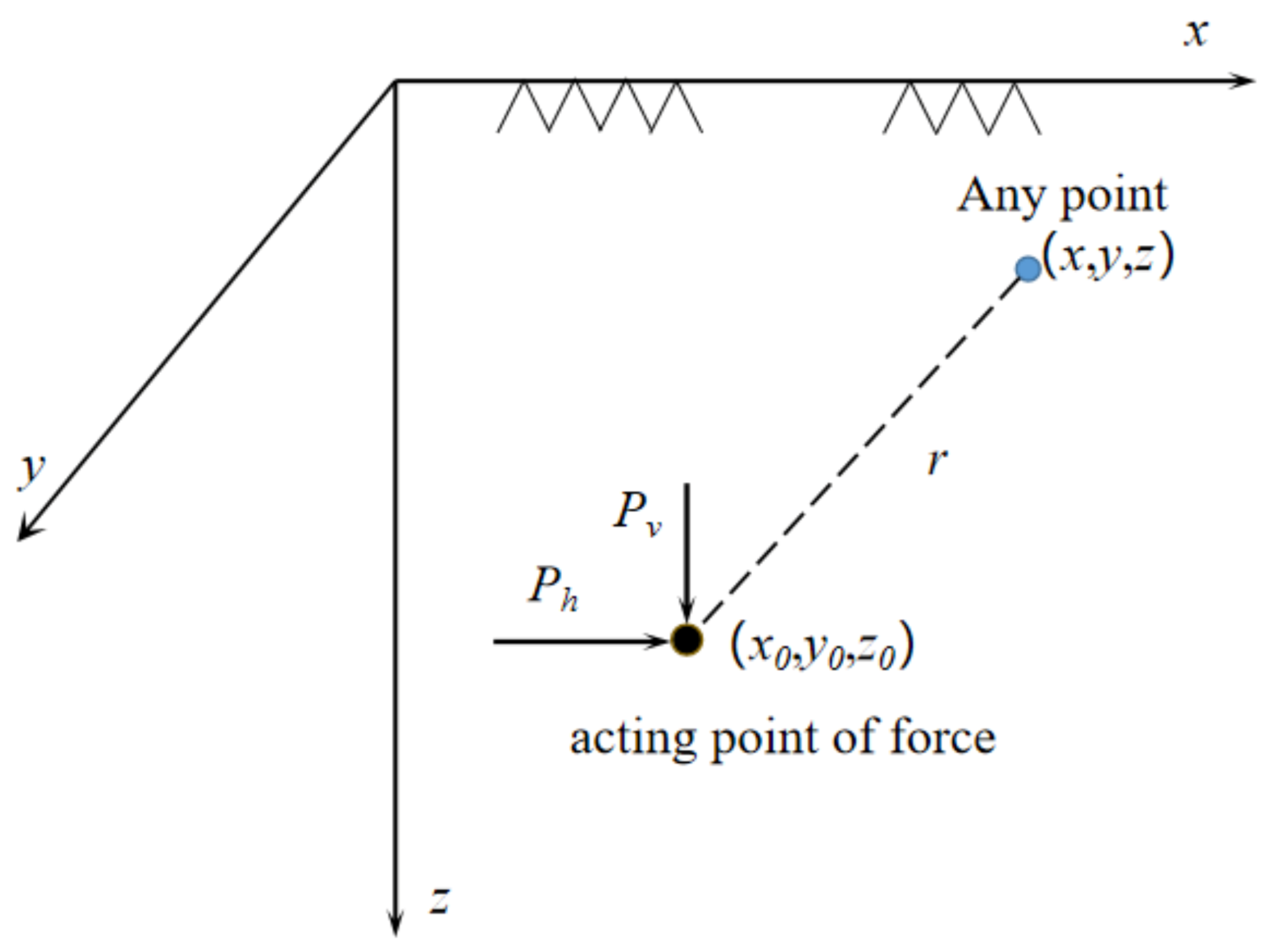
3.1. Mindlin Solution
3.1.1. Calculation of Deformation Caused by the Thrust Load
3.1.2. Calculation of Deformation Caused by Friction Load
3.1.3. Calculation of Deformation Caused by Grouting Load
3.2. Calculation of Deformation Caused by Ground Loss
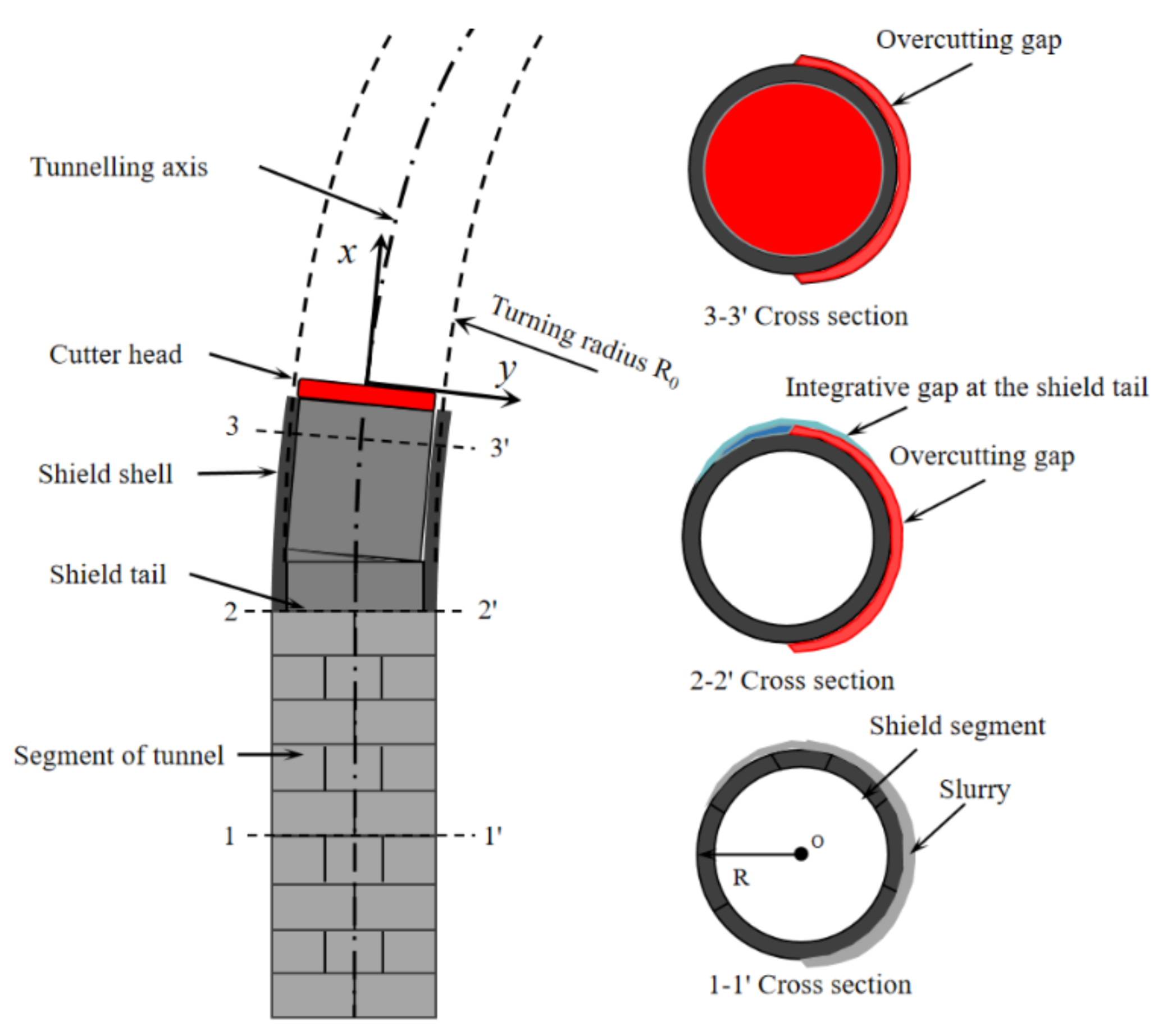
3.2.1. Calculation of Deformation Caused by the IGST
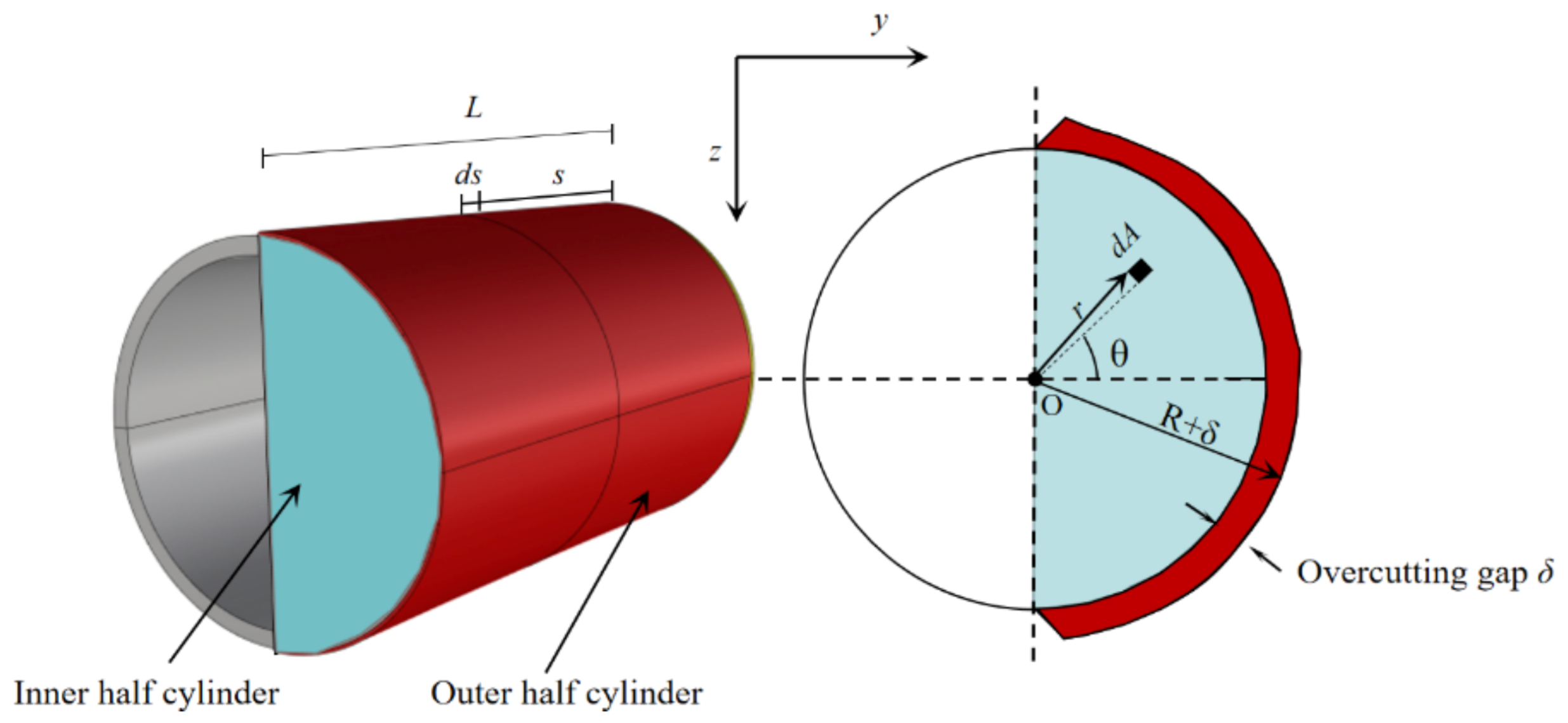
3.2.2. Calculation of Deformation Caused by OG
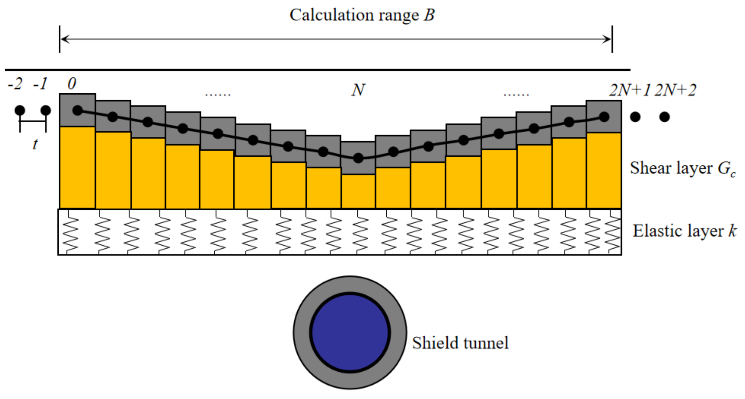
3.3. Calculation of Pipeline Deformation Consider Pipe–Soil Coupling
4. Numerical Calculation Model
4.1. Finite Difference Model
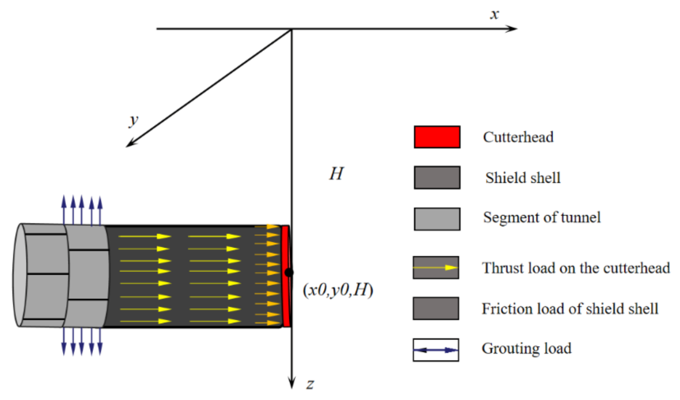
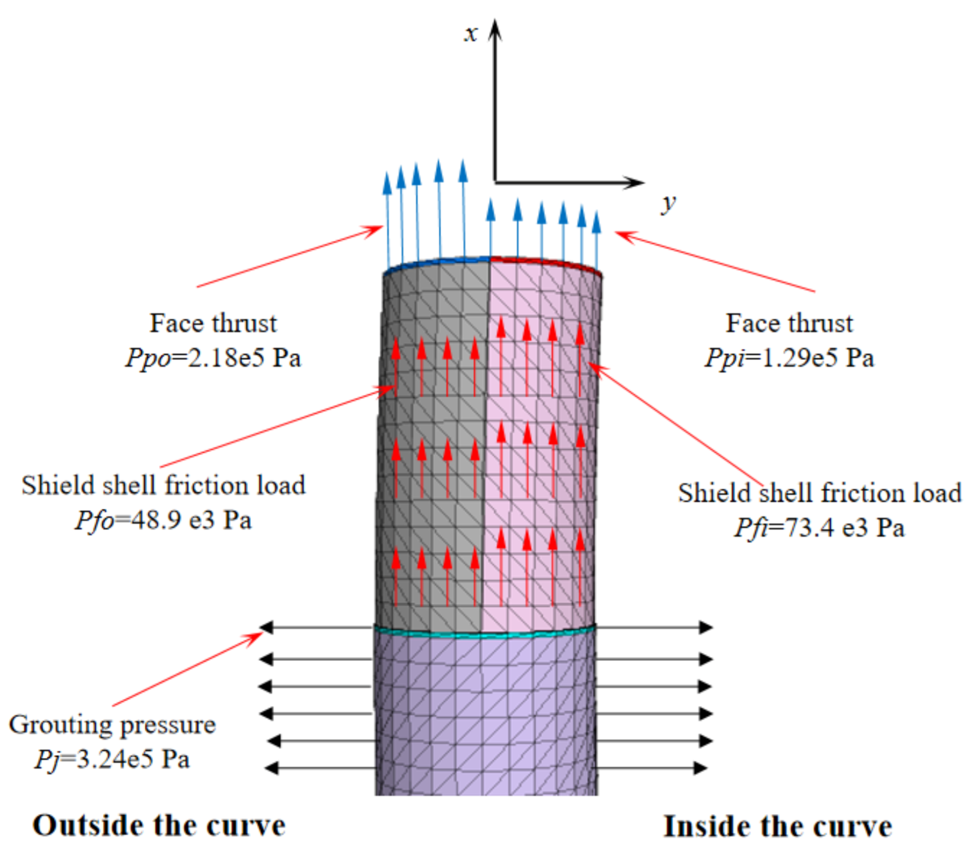
4.2. Loads in the Numerical Calculation Model
4.3. Material Properties
4.4. Numerical Simulation Process
5. Analysis of Calculation Results
5.1. Analysis of Surface Settlement
- (1)
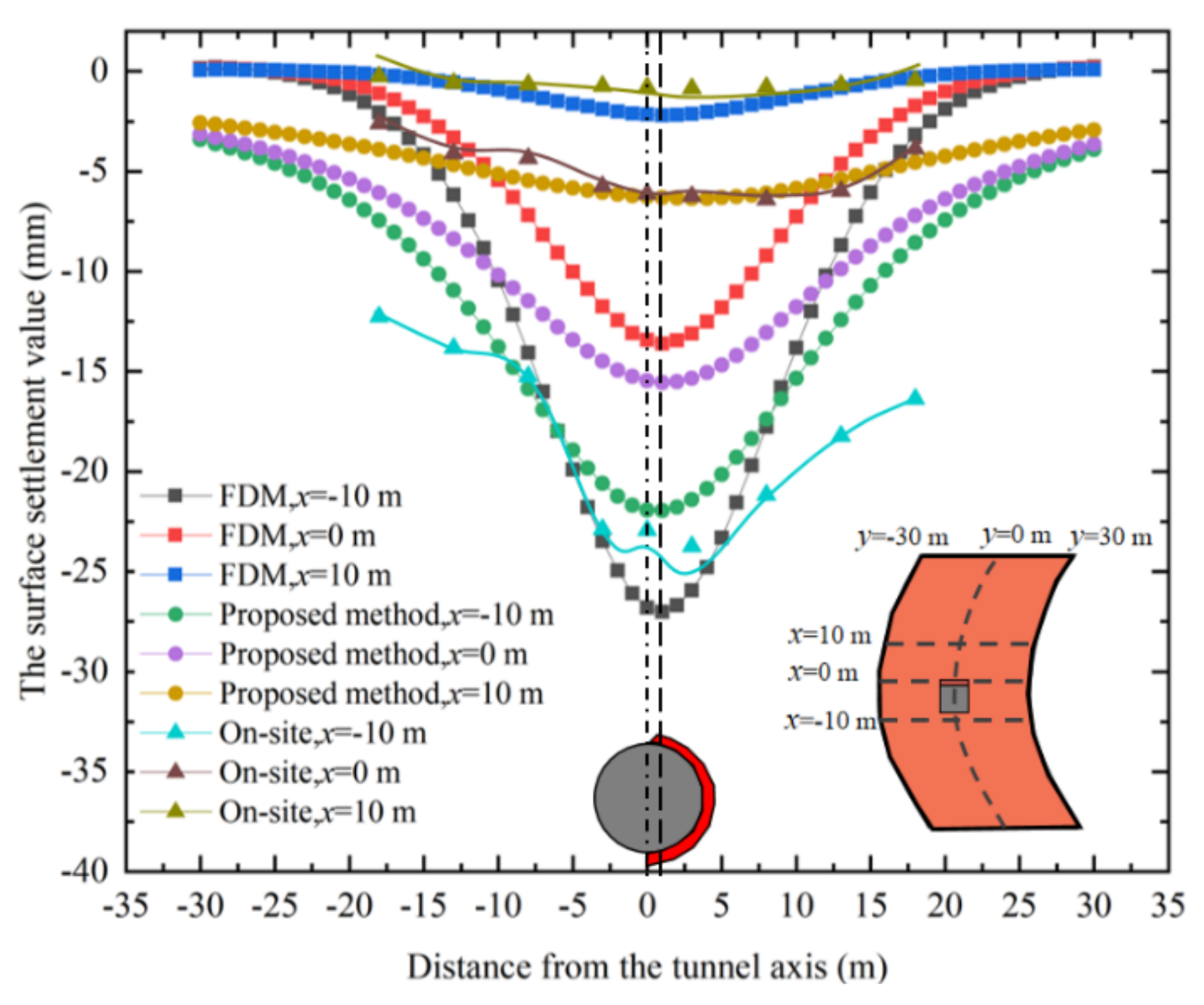
- Numerical simulation results, theoretical prediction results, and on-site monitoring data indicate that the maximum surface subsidence is 27 mm, 22 mm, and 24 mm, respectively, and the error range of the calculation results is within 10%. Thus, the rationality of the proposed prediction formula and FDM is verified.
- (2)
- When the shield machine is tunneling along the curved section, the ground settlement is distributed asymmetrically in a “V” shape, which is different from the ground settlement law in the case of tunneling along the straight section. The theoretical prediction results indicate that the maximum ground settlement position deviates from the tunnel axis, which is located inside the curved section approximately 1 m away from the tunnel axis. This law derived from theoretical calculations is consistent with that calculated by the FDM. The field monitoring data show that the surface settlement near the inside of the curved section is greater than that outside of the curved section; however, the maximum settlement position deviates to a greater degree.
- (3)
- Comparison of the data of the three monitoring sections indicates that in the monitoring section closer to the tail of the shield machine, the greater the surface settlement value, the more comprehensive the range of the surface settlement trough.
- (1)
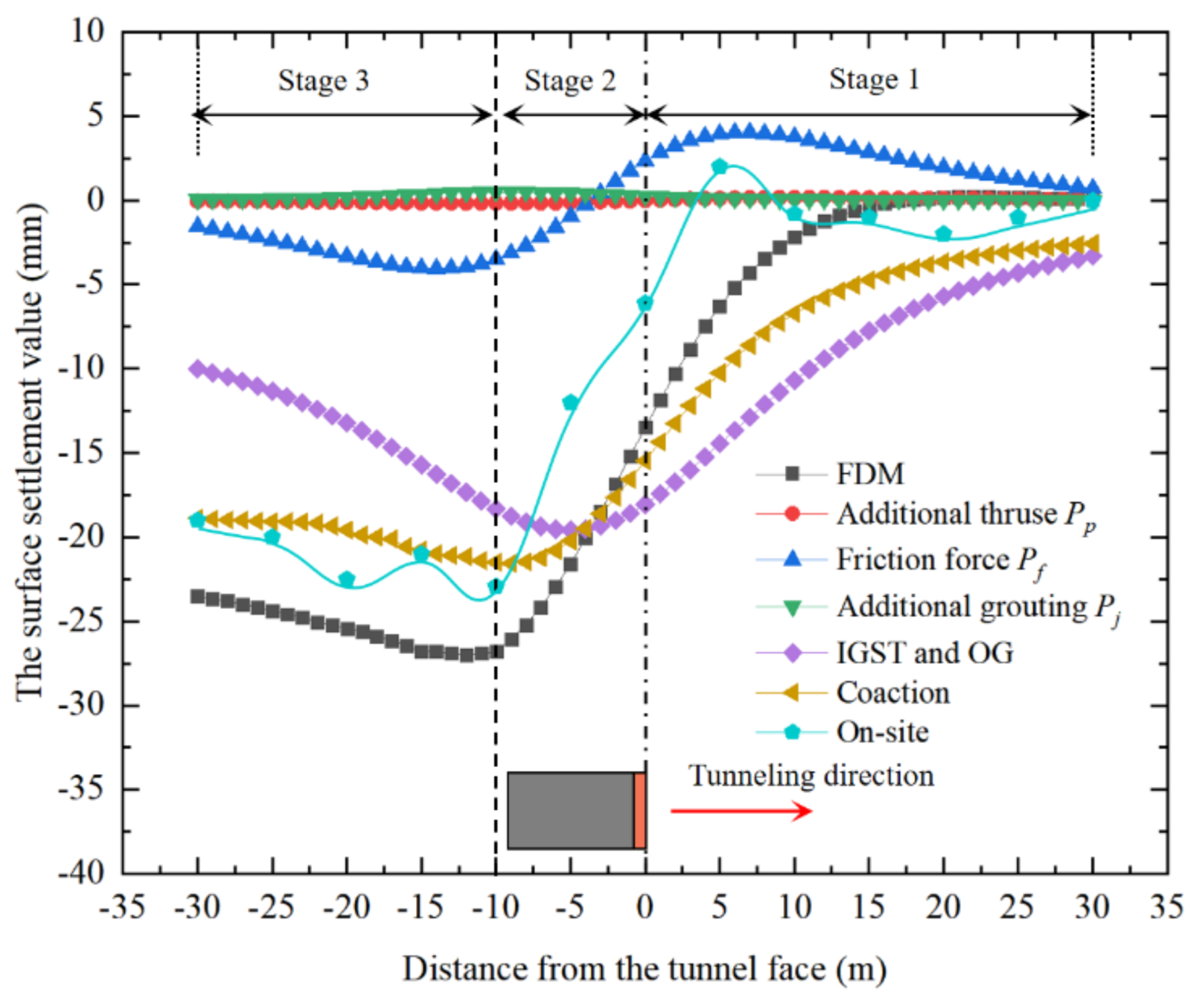
- The surface settlement curve along the direction of excavation is “S” shaped and can be divided into three stages: slow development stage (stage 1), intensive development stage (stage 2), and stable development stage (stage 3). This law of vertical distribution on the surface is consistent with that previously reported [48].
- (2)
- Among the shield machine construction factors discussed in this paper, the leading causes of the ground settlement are the friction load of the shield shell and ground loss. The additional thrust load and the grouting pressure have little effect on the ground settlement.
- (3)
- The maximum settlement of the ground surface is located behind the shield tail. The maximum settlements obtained by numerical simulation, theoretical calculation, and on-site monitoring are 26 mm, 22 mm, and 24 mm, respectively, at positions 12 m, 10 m, and 10 m, respectively, behind the cutter head. Once again, the above data prove the accuracy of the numerical calculation model and the proposed formula.
5.2. Pipeline Deformation Analysis
- (1)
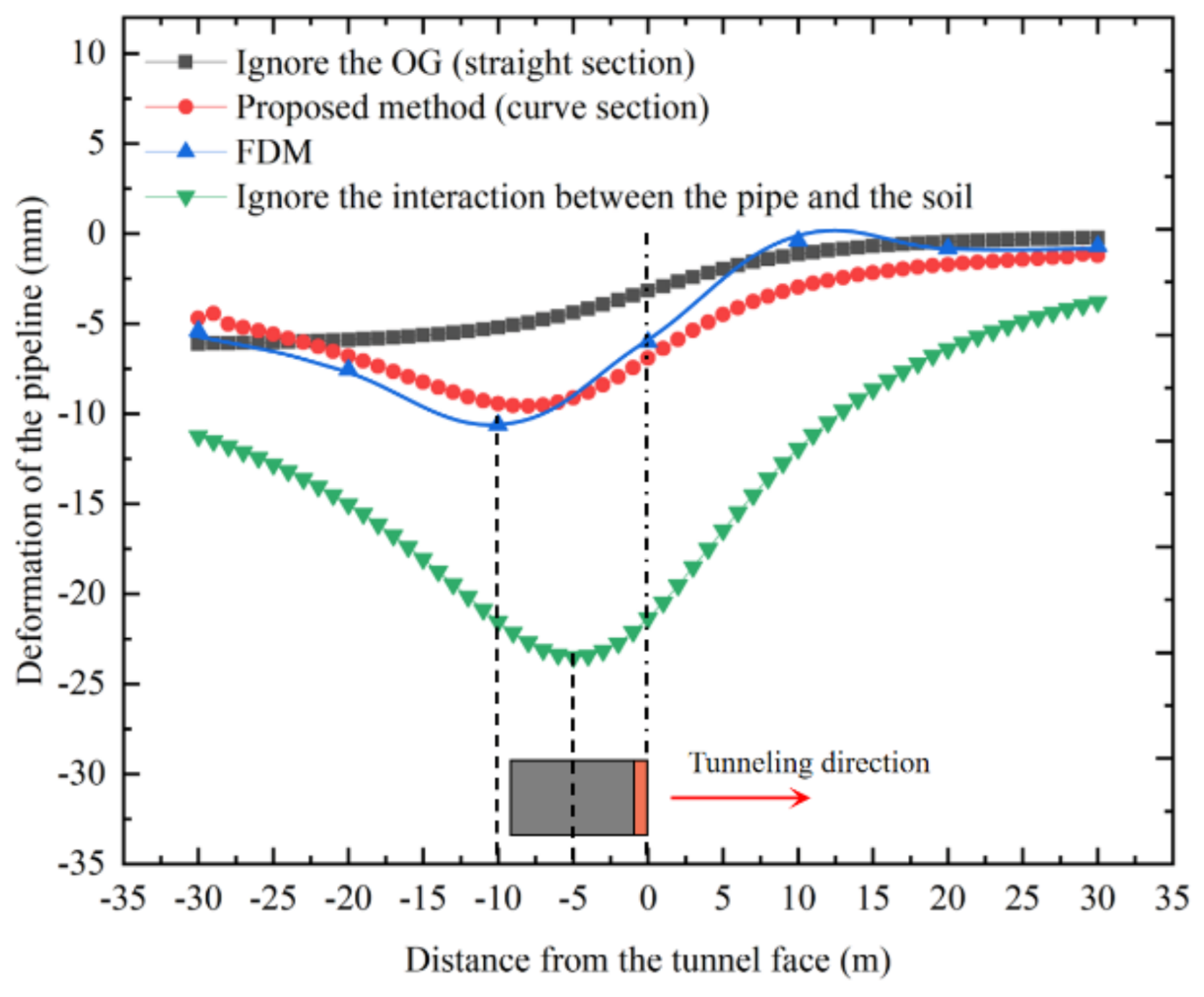
- Figure 19a shows that when the pipeline axis is parallel to the tunnel axis, the deformation of the pipeline is asymmetrically distributed in a “V” shape, and the maximum deformation position deviates from the tunnel axis. This is different from the law of surface settlement caused by tunneling along the straight section. The maximum deformation values of the pipeline according to the numerical simulation and theoretical calculation are approximately 11 mm and 9.5 mm, respectively.
- (2)
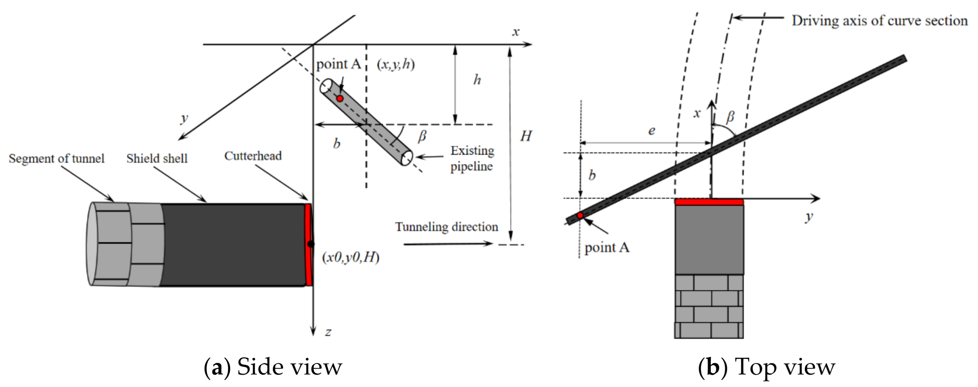
- Figure 19b shows that when the pipeline axis and the excavation axis intersect at x = −10 m, the change in the included angle β has little effect on the maximum deformation of the pipeline. Moreover, the maximum deformation position of the pipeline deviates from the tunnel axis by approximately 2 m.
- (3)
- Figure 19c shows that when the pipeline axis and the tunneling axis intersect at x = 0 m, the included angle β has a significant effect on the maximum deformation of the pipeline. With continuously increasing β, the maximum deformation value of the pipeline gradually decreases, and the maximum settlement position is closer to the tunnel axis.
6. Conclusions
- (1)
- The results of the proposed theoretical prediction, FDM calculation, and field monitoring data are consistent, with a small deviation; this verifies the rationality of the proposed formula.
- (2)
- When the shield machine is tunneling along the curved section, the horizontal deformation curves of the ground surface and the existing pipeline are asymmetrically distributed in a “V” shape, and the maximum settlement position appears on the inside of the curved section, which is around 0.5 R away from the tunnel axis. By contrast, the longitudinal deformation curves of the ground surface and the pipeline are distributed in an “S” shape, and the maximum settlement position is behind the shield tail. The shield shell friction and ground loss are the main factors affecting the surrounding stratum during the tunneling process.
- (3)
- When the pipeline axis and the tunneling axis intersect behind the cutter head, the included angle β between the pipe axis and the excavation axis does not affect the maximum deformation and position of the deformation. However, when both axes intersect before the cutter head, the maximum deformation of the pipe increases, and the position of maximum deformation gradually becomes closer to the tunnel axis with increasing β.
- (4)
- When analyzing the deformation of the existing pipeline caused by tunneling of the shield machine along the curved section, it is necessary to consider the ground loss caused by the OG and the coupling effect between the soil layer and the pipeline. In addition, the existing pipeline deformation and surface settlement caused by shield machine tunneling along the curved section is much larger than those caused by tunneling along the straight section. Therefore, special attention should be paid to the disturbance of the surrounding environment caused by shield machine tunneling along curved sections.
Author Contributions
Funding
Institutional Review Board Statement
Informed Consent Statement
Data Availability Statement
Acknowledgments
Conflicts of Interest
References
- Huang, M.; Zhou, X.; Yu, J.; Leung, C.; Tan, J.Q.W. Estimating the effects of tunnelling on existing jointed pipelines based on Winkler model. Tunn. Undergr. Space Technol. 2019, 86, 89–99. [Google Scholar] [CrossRef]
- Zhang, J.; Xie, R.; Zhang, H. Mechanical response analysis of the buried pipeline due to adjacent foundation pit excavation. Tunn. Undergr. Space Technol. 2018, 78, 135–145. [Google Scholar] [CrossRef]
- Ma, S.; Li, M.; Jin, J.; Bai, K. The influence of shallow buried double-line parallel rectangular pipe jacking construction on ground settlement deformation. Alex. Eng. J. 2021, 60, 1911–1916. [Google Scholar] [CrossRef]
- Fang, Q.; Zhang, D.; Li, Q.; Wong, L.N.Y. Effects of twin tunnels construction beneath existing shield-driven twin tunnels. Tunn. Undergr. Space Technol. 2015, 45, 128–137. [Google Scholar] [CrossRef]
- Zhang, D.-M.; Huang, Z.-K.; Li, Z.-L.; Zong, X. Analytical solution for the response of an existing tunnel to a new tunnel excavation underneath. Comput. Geotech. 2019, 108, 197–211. [Google Scholar] [CrossRef]
- Miliziano, S.; de Lillis, A. Predicted and observed settlements induced by the mechanized tunnel excavation of metro line C near S. Giovanni station in Rome. Tunn. Undergr. Space Technol. 2019, 86, 236–246. [Google Scholar] [CrossRef]
- Cheng, W.-C.; Song, Z.-P.; Tian, W.; Wang, Z.-F. Shield tunnel uplift and deformation characterisation: A case study from Zhengzhou metro. Tunn. Undergr. Space Technol. 2018, 79, 83–95. [Google Scholar] [CrossRef]
- Lin, X.-T.; Chen, R.-P.; Wu, H.-N.; Cheng, H. Deformation behaviors of existing tunnels caused by shield tunneling undercrossing with oblique angle. Tunn. Undergr. Space Technol. 2019, 89, 78–90. [Google Scholar] [CrossRef]
- Yu, C.; Han, C.; Xie, R.; Wang, L. Mechanical behavior analysis of buried pipeline under stratum settlement caused by underground mining. Int. J. Press. Vessel. Pip. 2020, 188, 188. [Google Scholar] [CrossRef]
- Cheng, H.; Chen, R.; Wu, H.; Meng, F.; Yi, Y. General solutions for the longitudinal deformation of shield tunnels with multiple discontinuities in strata. Tunn. Undergr. Space Technol. 2021, 107, 103652. [Google Scholar] [CrossRef]
- Ni, P.; Mangalathu, S. Fragility analysis of gray iron pipelines subjected to tunneling induced ground settlement. Tunn. Undergr. Space Technol. 2018, 76, 133–144. [Google Scholar] [CrossRef]
- Zhang, Z.; Zhang, M. Mechanical effects of tunneling on adjacent pipelines based on Galerkin solution and layered transfer matrix solution. Soils Found. 2013, 53, 557–568. [Google Scholar] [CrossRef] [Green Version]
- Hou, Y.; Fang, Q.; Zhang, D.; Wong, L.N.Y. Excavation failure due to pipeline damage during shallow tunnelling in soft ground. Tunn. Undergr. Space Technol. 2015, 46, 76–84. [Google Scholar] [CrossRef]
- Zhang, C.; Yu, J.; Huang, M. Effects of tunnelling on existing pipelines in layered soils. Comput. Geotech. 2012, 43, 12–25. [Google Scholar] [CrossRef]
- Zhang, M.; Li, S.; Li, P. Numerical analysis of ground displacement and segmental stress and influence of yaw excavation loadings for a curved shield tunnel. Comput. Geotech. 2020, 118, 103325. [Google Scholar] [CrossRef]
- Deng, H.-S.; Fu, H.-L.; Yue, S.; Huang, Z.; Zhao, Y.-Y. Ground loss model for analyzing shield tunneling-induced surface settlement along curve sections. Tunn. Undergr. Space Technol. 2021, 119, 104250. [Google Scholar] [CrossRef]
- Wu, D.; Xu, K.; Guo, P.; Lei, G.; Cheng, K.; Gong, X. Ground Deformation Characteristics Induced by Mechanized Shield Twin Tunnelling along Curved Alignments. Adv. Civ. Eng. 2021, 2021, 1–17. [Google Scholar] [CrossRef]
- Xie, X.; Tang, G. Effects of curved shield tunnelling adjacent to existing power tunnel. Eur. J. Environ. Civ. Eng. 2017, 22, s164–s178. [Google Scholar] [CrossRef]
- Liang, R.; Xia, T.; Hong, Y.; Yu, F. Effects of above-crossing tunnelling on the existing shield tunnels. Tunn. Undergr. Space Technol. 2016, 58, 159–176. [Google Scholar] [CrossRef]
- Mindlin, R.D. Force at a Point in the Interior of a Semi-Infinite Solid. Physics 1936, 7, 195–202. [Google Scholar] [CrossRef]
- Zhang, Q.; Hou, Z.; Huang, G.; Cai, Z.; Kang, Y. Mechanical characterization of the load distribution on the cutterhead–ground interface of shield tunneling machines. Tunn. Undergr. Space Technol. 2015, 47, 106–113. [Google Scholar] [CrossRef]
- Alsahly, A.; Stascheit, J.; Meschke, G. Advanced finite element modeling of excavation and advancement processes in mechanized tunneling. Adv. Eng. Softw. 2016, 100, 198–214. [Google Scholar] [CrossRef]
- Hirai, H. Settlements and stresses of multi-layered grounds and improved grounds by equivalent elastic method. Int. J. Numer. Anal. Methods Géoméch. 2008, 32, 523–557. [Google Scholar] [CrossRef]
- Cao, L.; Zhang, D.; Fang, Q. Semi-analytical prediction for tunnelling-induced ground movements in multi-layered clayey soils. Tunn. Undergr. Space Technol. 2020, 102, 103446. [Google Scholar] [CrossRef]
- Zhou, Z.; Chen, Y.; Liu, Z.; Miao, L. Theoretical prediction model for deformations caused by construction of new tunnels undercrossing existing tunnels based on the equivalent layered method. Comput. Geotech. 2020, 123, 103565. [Google Scholar] [CrossRef]
- Alonso, E.E.; Josa, A.; Ledesma, A. Negative skin friction on piles: A simplified analysis and prediction procedure. Géotechnique 1984, 34, 341–357. [Google Scholar] [CrossRef] [Green Version]
- Li, S.; Li, P.; Zhang, M. Analysis of additional stress for a curved shield tunnel. Tunn. Undergr. Space Technol. 2021, 107, 103675. [Google Scholar] [CrossRef]
- Nematollahi, M.; Dias, D. Three-dimensional numerical simulation of pile-twin tunnels interaction—Case of the Shiraz subway line. Tunn. Undergr. Space Technol. 2019, 86, 75–88. [Google Scholar] [CrossRef]
- Yin, M.; Jiang, H.; Jiang, Y.; Sun, Z.; Wu, Q. Effect of the excavation clearance of an under-crossing shield tunnel on existing shield tunnels. Tunn. Undergr. Space Technol. 2018, 78, 245–258. [Google Scholar] [CrossRef]
- Lee, K.M.; Rowe, R.K.; Lo, K.Y. Subsidence owing to tunnelling. I. Estimating the gap parameter. Can. Geotech. J. 1992, 29, 929–940. [Google Scholar] [CrossRef]
- Loganathan, N.; Poulos, H.G. Analytical Prediction for Tunneling-Induced Ground Movements in Clays. J. Geotech. Geoenvironm. Eng. 1998, 124, 846–856. [Google Scholar] [CrossRef]
- Huynh, T.; Chen, J.; Sugimoto, M. Analysis on shield operational parameters to steer articulated shield. Jpn. Geotech. Soc. Spéc. Publ. 2016, 2, 1497–1500. [Google Scholar] [CrossRef] [Green Version]
- Festa, D.; Broere, W.; Bosch, J. Kinematic behaviour of a Tunnel Boring Machine in soft soil: Theory and observations. Tunn. Undergr. Space Technol. 2015, 49, 208–217. [Google Scholar] [CrossRef]
- Sagaseta, C. Analysis of undraind soil deformation due to ground loss. Géotechnique 1987, 37, 301–320. [Google Scholar] [CrossRef]
- Mohanty, R. An unconditionally stable finite difference formula for a linear second order one space dimensional hyperbolic equation with variable coefficients. Appl. Math. Comput. 2005, 165, 229–236. [Google Scholar] [CrossRef]
- Liang, R.; Xia, T.; Huang, M.; Lin, C. Simplified analytical method for evaluating the effects of adjacent excavation on shield tunnel considering the shearing effect. Comput. Geotech. 2017, 81, 167–187. [Google Scholar] [CrossRef]
- Liang, L.; Xu, C.; Zhu, B.; Deng, J. Theoretical method for an elastic infinite beam resting on a deformable foundation with a local subsidence. Comput. Geotech. 2020, 127, 103740. [Google Scholar] [CrossRef]
- Liu, Z.; Xue, J.; Ye, J.; Qian, J. A simplified two-stage method to estimate the settlement and bending moment of upper tunnel considering the interaction of undercrossing twin tunnels. Transp. Geotech. 2021, 29, 100558. [Google Scholar] [CrossRef]
- El Kahi, E.; Deck, O.; Khouri, M.; Mehdizadeh, R.; Rahme, P. Influence of geometrical uncertainties of analytical modelling on the evaluation of building deflections induced by ground movements. Eur. J. Environ. Civ. Eng. 2020, 1–15. [Google Scholar] [CrossRef]
- Attewell, P.B.; Yeates, J.; Selby, A.R. Soil Movements Induced by Tunnelling and their Effects on Pipelines and Structures; Methuen Inc.: New York, NY, USA, 1986. [Google Scholar]
- Tanahashi, H. Formulas for an Infinitely Long Bernoulli-Euler Beam on the Pasternak Model. Soils Found. 2004, 44, 109–118. [Google Scholar] [CrossRef] [Green Version]
- Nematollahi, M.; Dias, D. Interaction between an underground parking and twin tunnels—Case of the Shiraz subway line. Tunn. Undergr. Space Technol. 2020, 95, 103150. [Google Scholar] [CrossRef]
- Potyondy, J.G. Skin Friction between Various Soils and Construction Materials. Géotechnique 1961, 11, 339–353. [Google Scholar] [CrossRef]
- Dai, X.; Cai, J.; Diao, Y.; Huo, H.; Xu, G. Influence of tunnelling on the deformation of the overlying excavation bracing system and analysis of countermeasures. Comput. Geotech. 2021, 134, 104089. [Google Scholar] [CrossRef]
- Lai, H.; Zheng, H.; Chen, R.; Kang, Z.; Liu, Y. Settlement behaviors of existing tunnel caused by obliquely under-crossing shield tunneling in close proximity with small intersection angle. Tunn. Undergr. Space Technol. 2020, 97, 103258. [Google Scholar] [CrossRef]
- Oggeri, C.; Oreste, P.; Spagnoli, G. The influence of the two-component grout on the behaviour of a segmental lining in tunnelling. Tunn. Undergr. Space Technol. 2021, 109, 103750. [Google Scholar] [CrossRef]
- Li, X.; Zhou, X.; Hong, B.; Zhu, H. Experimental and analytical study on longitudinal bending behavior of shield tunnel subjected to longitudinal axial forces. Tunn. Undergr. Space Technol. 2019, 86, 128–137. [Google Scholar] [CrossRef]
- Fang, Y.; Chen, Z.; Tao, L.; Cui, J.; Yan, Q. Model tests on longitudinal surface settlement caused by shield tunnelling in sandy soil. Sustain. Cities Soc. 2019, 47, 101504. [Google Scholar] [CrossRef]


| Soil Materials | γ (kN/m3) | φ (°) | c (kPa) | Et (MPa) | μ |
|---|---|---|---|---|---|
| Miscellaneous fill | 17.2 | 5 | 5 | 1.5 | 0.33 |
| Silty clay | 17.8 | 8 | 15 | 4.2 | 0.32 |
| Sand | 18.5 | 15 | 2 | 45.0 | 0.28 |
| Sand cobble | 18.8 | 30 | 32 | 62.4 | 0.25 |
| Mudstone | 19.2 | 35 | 50 | 147.8 | 0.23 |
| Shield Machine Material | γ (kN/m3) | E (GPa) | μ |
|---|---|---|---|
| Cutter head | 70 | 200 | 0.20 |
| Shield shell | 70 | 200 | 0.20 |
| Segment (C50) | 25.2 | 3.6 | 0.24 |
| Unsolidified area of the slurry | 0.0083 | 0.36 | |
| Solidification area of the slurry | 0.045 | 0.30 | |
| Existing pipeline (C20) | 20.3 | 2.3 | 0.26 |
| Model Number | b (m) | β (°) | h (m) | e (m) |
|---|---|---|---|---|
| 1 | −10 | 90 | 4 | ±30 |
| 2 | 0 | 90 | 4 | ±30 |
| 3 | 10 | 90 | 4 | ±30 |
| 4 | −10 | 30 | 4 | ±30 |
| 5 | −10 | 45 | 4 | ±30 |
| 6 | −10 | 60 | 4 | ±30 |
| 7 | 0 | 30 | 4 | ±30 |
| 8 | 0 | 45 | 4 | ±30 |
| 9 | 0 | 60 | 4 | ±30 |
| 10 | −20 | 90 | 4 | ±30 |
| 11 | −30 | 90 | 4 | ±30 |
| 12 | 20 | 90 | 4 | ±30 |
| 13 | 30 | 90 | 4 | ±30 |
Publisher’s Note: MDPI stays neutral with regard to jurisdictional claims in published maps and institutional affiliations. |
© 2021 by the authors. Licensee MDPI, Basel, Switzerland. This article is an open access article distributed under the terms and conditions of the Creative Commons Attribution (CC BY) license (https://creativecommons.org/licenses/by/4.0/).
Share and Cite
Deng, H.; Fu, H.; Shi, Y.; Huang, Z.; Huang, Q. Analysis of Asymmetrical Deformation of Surface and Oblique Pipeline Caused by Shield Tunneling along Curved Section. Symmetry 2021, 13, 2396. https://doi.org/10.3390/sym13122396
Deng H, Fu H, Shi Y, Huang Z, Huang Q. Analysis of Asymmetrical Deformation of Surface and Oblique Pipeline Caused by Shield Tunneling along Curved Section. Symmetry. 2021; 13(12):2396. https://doi.org/10.3390/sym13122396
Chicago/Turabian StyleDeng, Huangshi, Helin Fu, Yue Shi, Zhen Huang, and Qibing Huang. 2021. "Analysis of Asymmetrical Deformation of Surface and Oblique Pipeline Caused by Shield Tunneling along Curved Section" Symmetry 13, no. 12: 2396. https://doi.org/10.3390/sym13122396
APA StyleDeng, H., Fu, H., Shi, Y., Huang, Z., & Huang, Q. (2021). Analysis of Asymmetrical Deformation of Surface and Oblique Pipeline Caused by Shield Tunneling along Curved Section. Symmetry, 13(12), 2396. https://doi.org/10.3390/sym13122396