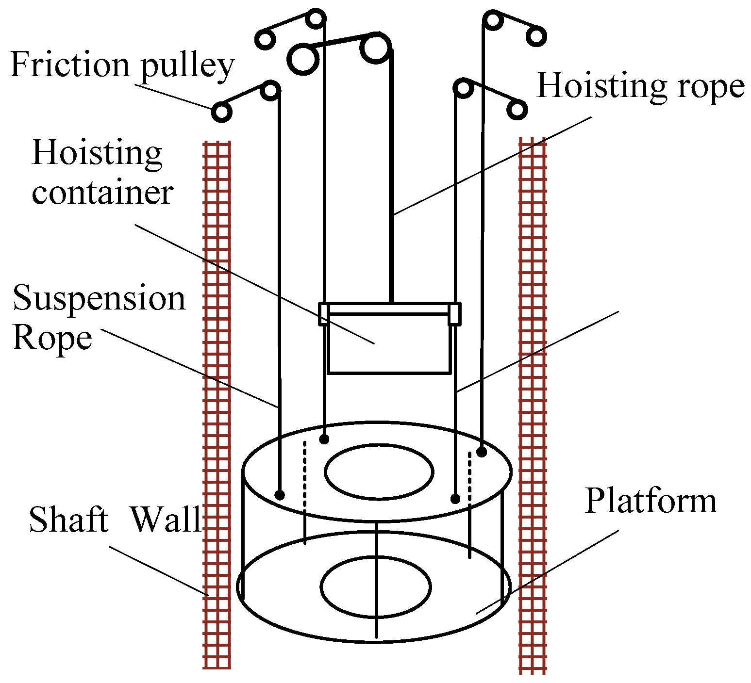
Schematic Diagrams Design of Displacement Suppression Mechanism with One Degree-of-Freedom in a Rope-Guided Hoisting System


Abstract
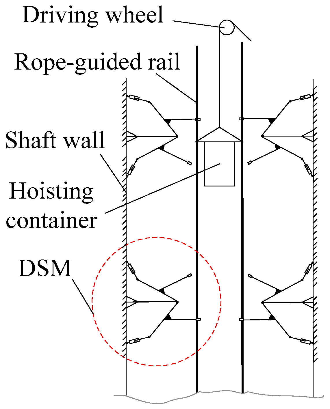
:1. Introduction
- (1)
- One of the mechanical parts of DSM is capable of swinging within a certain angle.
- (2)
- The mechanism can be locked at the limited position.
- (3)
- It is a 1-DOF planar structure in order to implement easily.
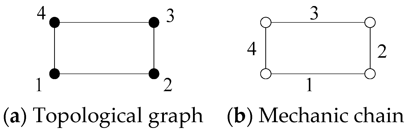
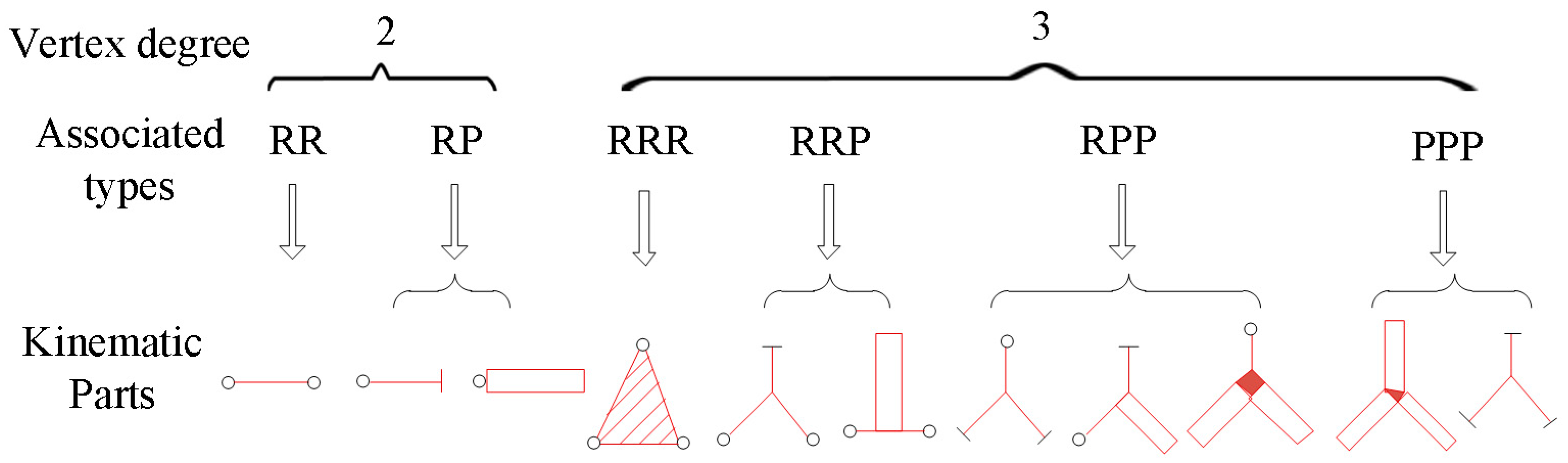
2. Topology Design for DSM
3. Connected Relations of Graphs
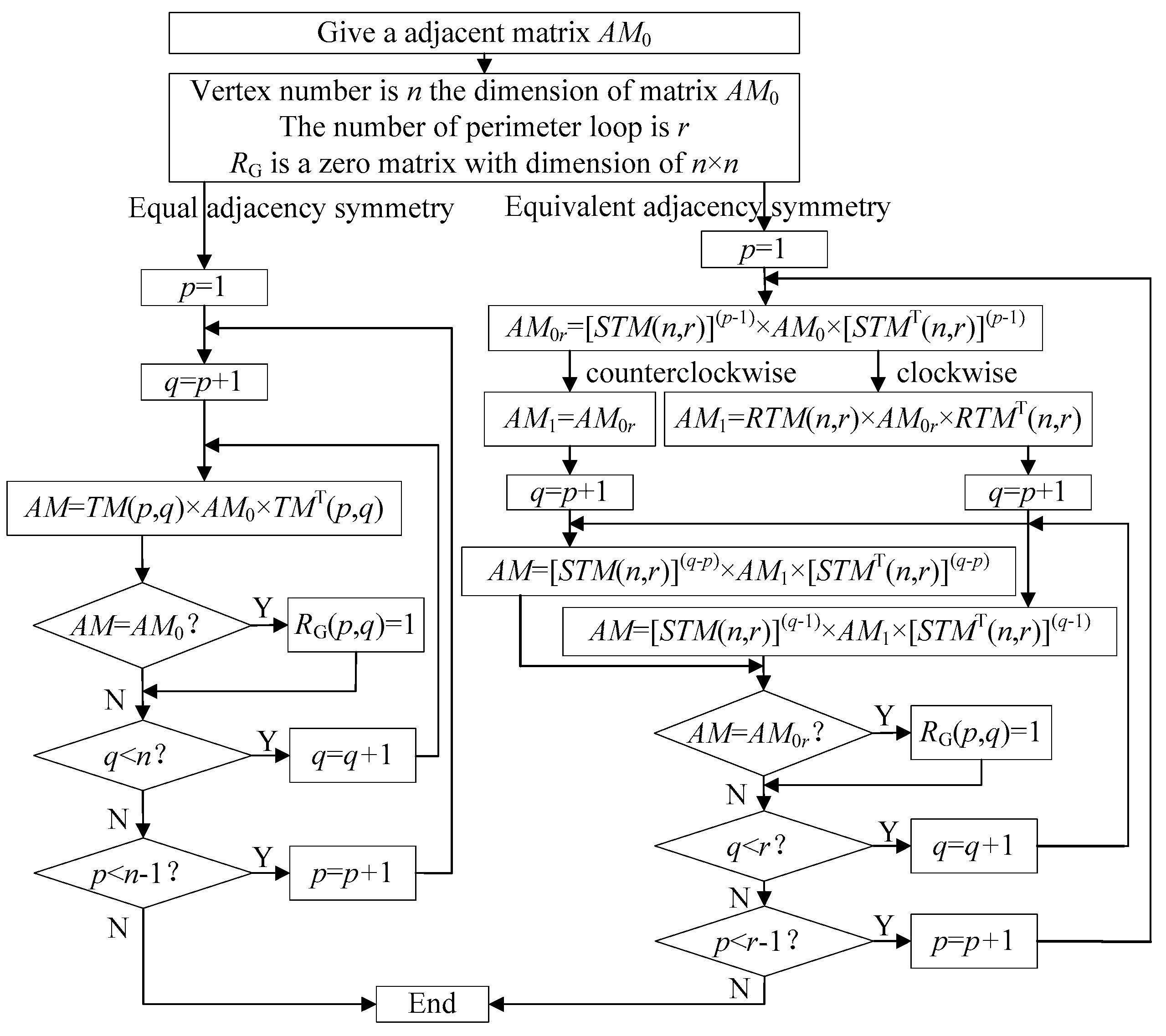
3.1. Adjacency Relation of Topological Graph
3.2. Adjacency Relation of Mechanism Diagram
3.3. Vertexes Symmetry Identification
- 1)
- Topological graphs are numbered on the basis of the perimeter loop theory and two vertexes to be identified are both in the canonical perimeter loop.
- 2)
- There is only one branch path outside the canonical perimeter loop.
- 3)
- Topological vertexes in sub-chain are no more than one.
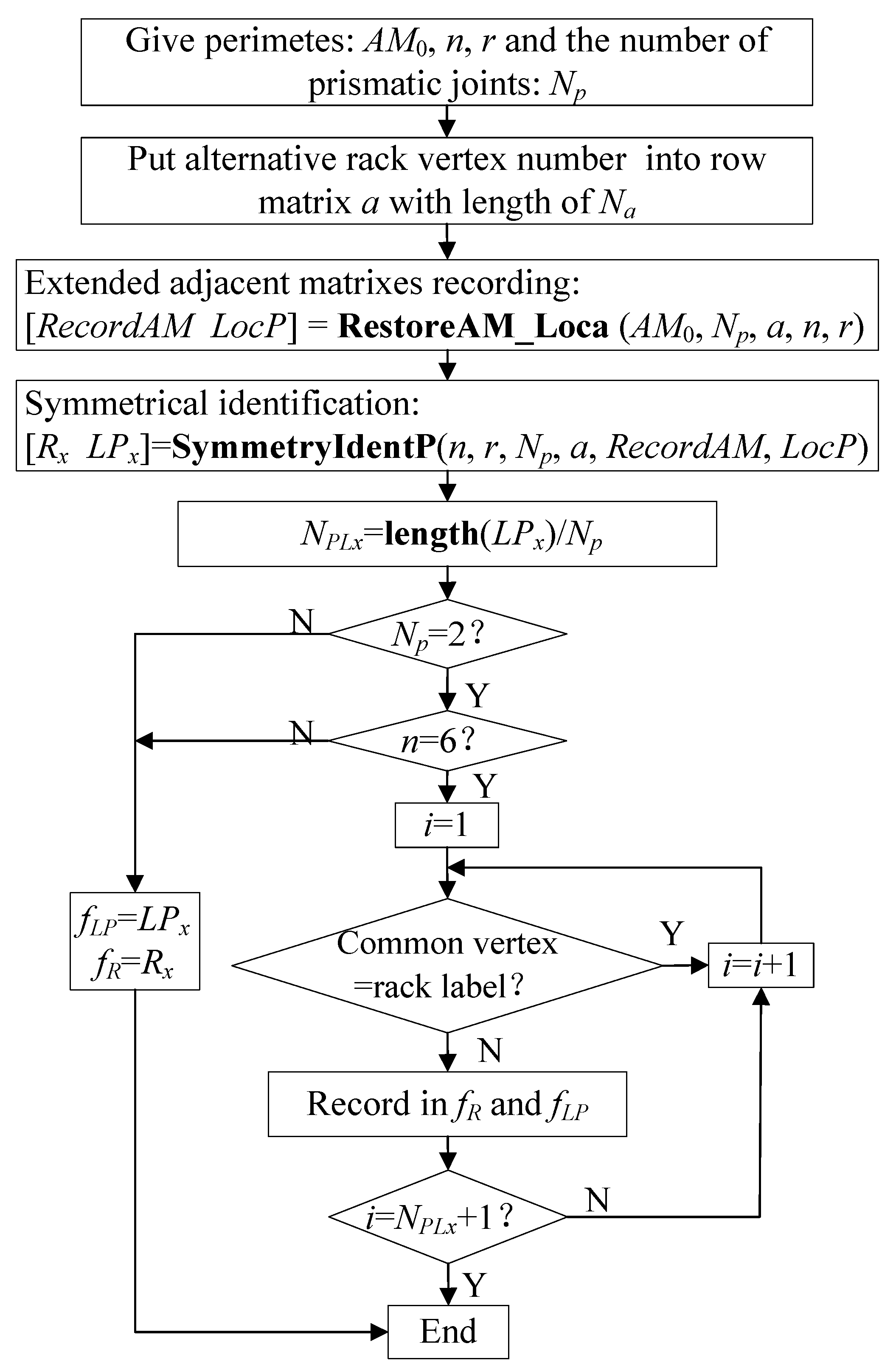
4. Computational Identification
- (i)
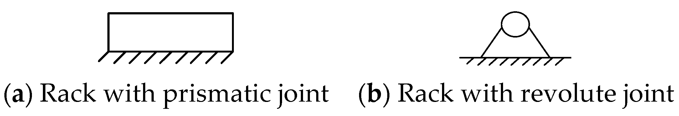
- Determine label number of mechanical rack: Two vertexes with topological symmetry form a vertex pair. All vertex pairs can be determined by symmetry identification of a topological graph. Among these symmetrical vertex pairs, the vertices between which have topological asymmetry, are chosen as labels of mechanical rack. The vertex labels of alternative rack are put into row matrix a with the length of Na.
- (ii)
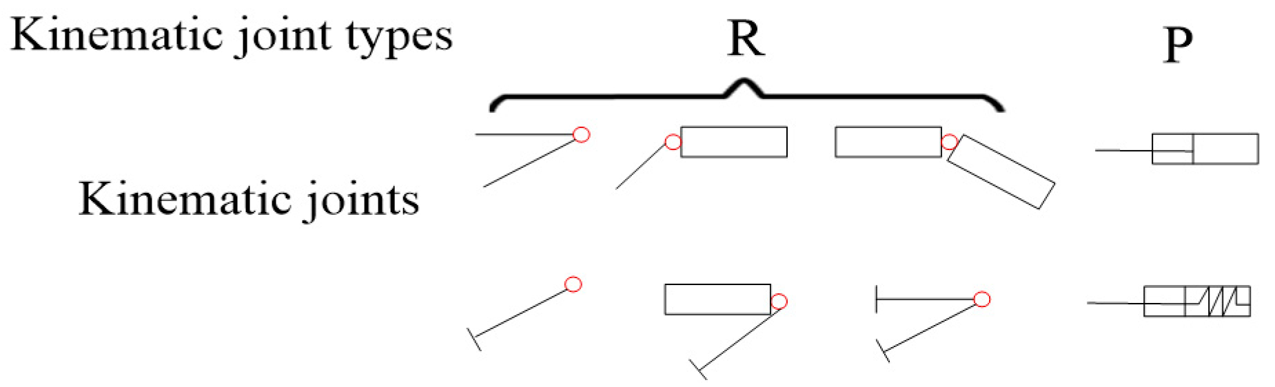
- Determine the number of prismatic joints: Since revolute joints are generally used in DSM and more prismatic joints will lead to more different mechanism diagram, one or two prismatic joints are both considered in the process to get mechanism diagrams. Np is used to denote the number of prismatic joints.
- (iii)
- Obtain all possible extended adjacent matrixes: All extended adjacent matrixes of mechanism diagrams with one or two prismatic joints are put into the matrix RecordAM for the following symmetry identifications. Corresponding rack vertex label and the labels of vertexes connected by prismatic joints are stored into matrix LocP. [RecordAM_LocP] = RestoreAM_Loca (AM0, Np, a, n, r), where RestoreAM_Loca () is a user-defined MATLAB function.
- (iv)
- Symmetry identification of mechanism diagrams: One extended adjacent matrix EAM is taken out from RecordAM to compare with another extended adjacent matrix EAMx one by one. If EAM ≠ EAMx, record EAM in matrix Rx and record the corresponding rack and prismatic joints information from LocP in matrix Lpx; otherwise, abnegate EAM and identify the next one. [Rx LPx] = SymmetryIdentP (n, r, Np, a, RecordAM, LocP), where SymmetryIdentP () is a user-defined MATLAB function.
- (v)
- Discard the mechanism diagrams with two consecutive prismatic joints in a six-bar mechanism except those both connected with mechanism rack: Two consecutive prismatic joints mean a mechanical part is connected with other two parts both by prismatic joints, which leads to a more complex structure and more difficult diagram design relative to that in a four-bar mechanism. Since a mechanism rack is immovable, its position can be quickly determined according to required movement. The number of alternative mechanisms is NPLx = length (LPx)/Np, where length () is a MATLAB function to obtain the matrix length. If the common vertex of two consecutive prismatic joints is not equal to rack label, a corresponding extended adjacent matrix from matrix Rx and a matrix of rack and prismatic joints information from Lpx will be recorded in matrixes fR and fLP, respectively.
- (vi)
- Abandon six-bar mechanism diagrams with all prismatic joints in four-bar sub-loops and the mechanisms for which any prismatic joint exist in a sub-loop without a mechanism rack: From objective topological graphs, a sub-loop of a six-bar topological graph is four vertexes and will be substituted with four mechanical parts in a conversion process to the mechanism diagram. A six-bar mechanism with all prismatic joints existing in a four-bar sub-loop is almost equivalent to four-bar mechanisms, due to the following movement of the other sub-chain. In addition, if prismatic joints exist in this sub-loop without mechanism rack, there is little possibility to achieve locking in a limited position because the function is achieved by setting prismatic joints and a mechanism rack in the same sub-loop. Therefore, the above conditions can be neglected.
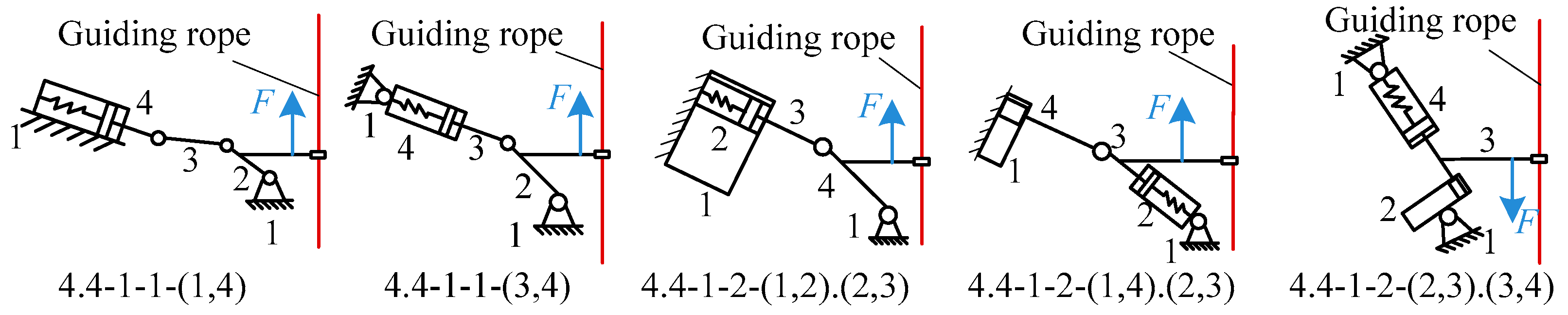
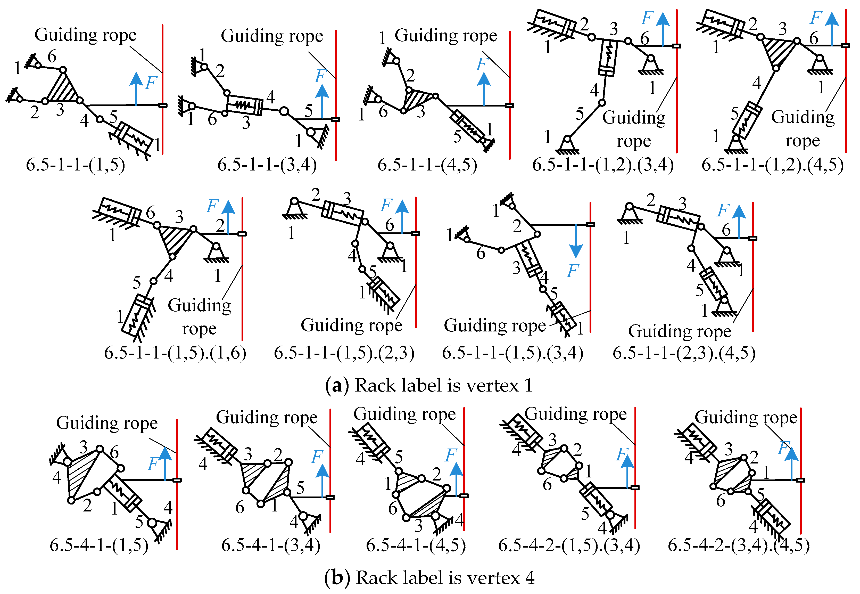
5. Alternatives for DSM and Results
6. Conclusions
Author Contributions
Funding
Acknowledgments
Conflicts of Interest
References
- Greenway, E.M. Lateral stiffness and deflection of vertical ropes with application to mine shaft hoisting. Aust. J. Mech. Eng. 2008, 5, 59–70. [Google Scholar] [CrossRef]
- Yan, L.; Cao, G.; Wang, N.; Li, J. Lateral stiffness and deflection characteristics of guide cable with multi-boundary constraints. Adv. Mech. Eng. 2017, 9. [Google Scholar] [CrossRef] [Green Version]
- Cao, G.; Wang, J.; Zhu, Z. Coupled vibrations of rope-guided hoisting system with tension difference between two guiding ropes. Proc. Inst. Mech. Eng. Part. C. J. Mech. Eng. Sci. 2018, 232, 231–244. [Google Scholar] [CrossRef]
- Wang, J.; Pi, Y.; Hu, Y.; Gong, X. Modeling and dynamic behavior analysis of a coupled multi-cable double drum winding hoister with flexible guides. Mech. Mach. Theory 2017, 108, 191–208. [Google Scholar] [CrossRef]
- Cao, G.; Wang, J.; Zhu, Z. Guide rail rope deflection inhibition mechanism and method for parallel soft cable suspension system. US Invention Patent US09689257B2, 22 January 2014. [Google Scholar]
- Yan, H.; Chiu, Y. On the number synthesis of kinematic chains. Mech. Mach. Theory 2015, 89, 128–144. [Google Scholar] [CrossRef]
- Uicker, J.J.; Raicu, A. A Method for the Identification of and Recognition of Equivalence of Kinematic Chains. Mech. Mach. Theory 1975, 10, 375–383. [Google Scholar] [CrossRef]
- Rao, A.C.; Varada, R.D. Application of the hamming number technique to detect isomorphism among kinematic chains and inversion. Mech. Mach. Theory 1991, 26, 55–75. [Google Scholar] [CrossRef]
- Yang, P.; Pei, Z.H.; Liao, N.B.; Yang, B. Isomorphism identification for epicyclic gear mechanism based on mapping property and ant algorithm. Eng. Comput. 2007, 23, 49–54. [Google Scholar] [CrossRef]
- Kong, F.G.; Li, Q.; Zhang, W.J. An artificial neural network approach to mechanism kinematic chain isomorphism identification. Mech. Mach. Theory 1999, 34, 271–283. [Google Scholar] [CrossRef]
- Rao, A.C. A Genetic Algorithm for Topological Characteristics of Kinematic Chains. J. Mech. Des. 2000, 122, 228–231. [Google Scholar] [CrossRef]
- Xiao, R.; Tao, Z.; Liu, Y. Isomorphism identification of kinematic chains using novel evolutionary approaches. Trans. ASME J. Comput. Inf. Sci. Eng. 2005, 5, 18–24. [Google Scholar] [CrossRef]
- Galán-Marín, G.; López-Rodríguez, D.; Mérida-Casermeiro, E. A new multivalued neural network for isomorphism identification of kinematic chains. J. Comput. Inf. Sci. Eng. 2010, 10, 011009. [Google Scholar] [CrossRef]
- Chang, Z.Y.; Zhang, C.; Yang, Y.H.; Wang, Y.X. A new method to mechanism kinematic chain isomorphism identification. Mech. Mach. Theory 2002, 37, 411–417. [Google Scholar] [CrossRef]
- Cubillo, J.P.; Wan, J.B. Comments on mechanism kinematic chain isomorphism identification using adjacent matrices. Mech. Mach. Theory 2005, 40, 131–139. [Google Scholar] [CrossRef]
- Kuo, C.H.; Shih, C.J. Computational identification of link adjacency and joint incidence in kinematic chains and mechanisms. J. Mech. Des. 2008, 130, 084501. [Google Scholar] [CrossRef]
- Rao, A.C.; Deshmukh Pratap, B. Computer aided structural synthesis of planar kinematic chains obviating the test for isomorphism. Mech. Mach. Theory 2001, 36, 489–506. [Google Scholar] [CrossRef]
- Huber, M. Computational complexity of reconstruction and isomorphism testing for designs and line graphs. J. Comb. Theory Ser. A 2011, 118, 341–349. [Google Scholar] [CrossRef] [Green Version]
- Zeng, K.; Fan, X.; Dong, M.; Yang, P. A fast algorithm for kinematic chain isomorphism identification based on dividing and matching vertices. Mech. Mach. Theory 2014, 72, 25–38. [Google Scholar] [CrossRef]
- Yang, F.; Deng, Z.; Tao, J.; Li, L. A new method for isomorphism identification in topological graphs using incident matrices. Mech. Mach. Theory 2012, 49, 298–307. [Google Scholar] [CrossRef]
- Ding, H.F.; Huang, Z. The establishment of the canonical perimeter topological graph of kinematic chains and isomorphism identification. J. Mech. Des. 2006, 129, 915–923. [Google Scholar] [CrossRef]
- Ding, H.; Zhao, J.; Huang, Z. Unified structural synthesis of planar simple and multiple joint kinematic chains. Mech. Mach. Theory 2010, 45, 555–568. [Google Scholar] [CrossRef]
- Ding, H.; Hou, F. Synthesis of the whole family of planar 1-DOF kinematic chains and creation of their atlas database. Mech. Mach. Theory 2012, 47, 1–15. [Google Scholar] [CrossRef]
- Wu, X.H.; Nie, S.H.; Li, N. An approach of original loop to automatic sketching of planar kinematic chains. Mech. Sci. Technol. Aerosp. Eng. 2009, 28, 546–552. [Google Scholar]
- Nie, S.H.; Liu, H. Maximal Loop Method of Automatic Sketching of Planar Closed Kinematic Chains. J. Mech. Eng. 2009, 45, 30–37. [Google Scholar] [CrossRef]
- Rai, R.K.; Punjabi, S. Kinematic chains isomorphism identification using link connectivity number and entropy neglecting tolerance and clearance. Mech. Mach. Theory 2018, 123, 40–65. [Google Scholar] [CrossRef]
- Deng, T.; Xu, H.; Tang, P.; Liu, P.; Yan, L. A novel algorithm for the isomorphism detection of various kinematic chains using topological index. Mech. Mach. Theory 2020, 146, 103740. [Google Scholar] [CrossRef]
- Rao, A.C.; Nageswara Rao, C. Isomorphism among kinematic chains with Sliding Pairs. Indian J. Technol. 1989, 27, 363–365. [Google Scholar]
- Eleashy, H. A new atlas for 8-bar kinematic chains with up to 3 prismatic pairs using Joint Sorting Code. Mech. Mach. Theory 2018, 124, 118–132. [Google Scholar] [CrossRef]
- Dharanipragada, V.; Chintada, M. Split hamming string as an isomorphism test for one degree-of-freedom planar simple-jointed kinematic chains containing sliders. J. Mech. Des. 2016, 138, 082301–082308. [Google Scholar] [CrossRef]
- Sun, W.; Kong, J.Y.; Wang, X.D.; Hou, Y. Description and isomorphism judgment of the kinematic chain with multiple joints based on link-link adjacency matrix. J. Mech. Eng. 1–6. Available online: http://kns.cnki.net/kcms/detail/11.2187.TH.20191224.1509.176.html (accessed on 25 December 2019).
- Liu, H.; Shi, S.Y.; Yang, P.; Yang, J. An improved genetic algorithm approach on mechanism kinematic structure enumeration with intelligent manufacturing. J. Intell. Robot. Syst. 2018, 89, 343–350. [Google Scholar] [CrossRef]


| Topological Graph | Four Bar | Six Bar with r = 5 | Six Bar with r = 6 |
|---|---|---|---|
| Symmetric vertex pairs | 1~2, 1~3, 1~4, 2~3, 2~4, 3~4 | 2~6, 1~3, 4~5 | 1~4, 2~3, 2~5, 2~6, 3~5, 3~6, 5~6 |
| Mechanism rack label | 1 | 1, 2, 4 | 1, 2 |
| Topological Graph | Four Bar | Six Bar with r = 5 | Six Bar with r = 6 | |||||||||
|---|---|---|---|---|---|---|---|---|---|---|---|---|
| Rack | 1 | 1 | 2 | 4 | 1 | 2 | ||||||
| Np | 1 | 2 | 1 | 2 | 1 | 2 | 1 | 2 | 1 | 2 | 1 | 2 |
| NR | 4 | 6 | 7 | 21 | 7 | 21 | 7 | 21 | 7 | 21 | 7 | 21 |
| Nlpx | 2 | 4 | 5 | 13 | 4 | 12 | 6 | 13 | 4 | 12 | 7 | 21 |
| Nf | 2 | 4 | 5 | 8 | 4 | 7 | 6 | 7 | 4 | 8 | 7 | 12 |
| Nz | 2 | 4 | 3 | 6 | 0 | 0 | 3 | 2 | 0 | 5 | 0 | 0 |
| Topological Graph | Four Bar | Six Bar with r = 5 | Six Bar with r = 6 | ||||
|---|---|---|---|---|---|---|---|
| Rack | 1 | 1 | 2 | 4 | 1 | 2 | |
| Prismatic joints | Np = 1 | (1,4) | (1,5) | (1,5) | |||
| (3,4) | (3,4) | (3,4) | |||||
| (4,5) | (4,5) | ||||||
| Np = 2 | (1,2).(1,4) | (1,2).(3,4) | (1,5).(3,4) | (1,2).(1,6) | |||
| (1,2).(2,3) | (1,2).(4,5) | (3,4).(4,5) | (1,6).(2,3) | ||||
| (1,4).(2,3) | (1,5).(1,6) | (1,6).(3,4) | |||||
| (2,3).(3,4) | (1,5).(2,3) | (2,3).(5,6) | |||||
| (1,5).(3,4) | (3,4).(5,6) | ||||||
| (2,3).(4,5) | |||||||
© 2020 by the authors. Licensee MDPI, Basel, Switzerland. This article is an open access article distributed under the terms and conditions of the Creative Commons Attribution (CC BY) license (http://creativecommons.org/licenses/by/4.0/).
Share and Cite
Yan, L.; Cao, G.; Wang, N.; Peng, W. Schematic Diagrams Design of Displacement Suppression Mechanism with One Degree-of-Freedom in a Rope-Guided Hoisting System. Symmetry 2020, 12, 474. https://doi.org/10.3390/sym12030474
Yan L, Cao G, Wang N, Peng W. Schematic Diagrams Design of Displacement Suppression Mechanism with One Degree-of-Freedom in a Rope-Guided Hoisting System. Symmetry. 2020; 12(3):474. https://doi.org/10.3390/sym12030474
Chicago/Turabian StyleYan, Lu, Guohua Cao, Naige Wang, and Weihong Peng. 2020. "Schematic Diagrams Design of Displacement Suppression Mechanism with One Degree-of-Freedom in a Rope-Guided Hoisting System" Symmetry 12, no. 3: 474. https://doi.org/10.3390/sym12030474
APA StyleYan, L., Cao, G., Wang, N., & Peng, W. (2020). Schematic Diagrams Design of Displacement Suppression Mechanism with One Degree-of-Freedom in a Rope-Guided Hoisting System. Symmetry, 12(3), 474. https://doi.org/10.3390/sym12030474