1. Introduction
Due to the development of outsourced storage in the cloud, reversible watermarking in an encrypted domain has been developed for security in the cloud [
1,
2,
3,
4]. However, the cloud cannot introduce distortion of original content during watermark embedding. Therefore, the reversible watermarking method is required [
5,
6]. In addition, the watermark carrier is vulnerable during transmission, and the embedded watermark is expected to resist common attacks [
7,
8]. Therefore, robust reversible watermarking in an encrypted domain has greatly attracted researchers for potential applications.
In general, watermarking can be divided into robust and fragile watermarking methods in terms of their robustness. Robust watermarking [
9] is used to protect security and resist attacks, while fragile watermarking [
10,
11] is used to provide integrity authentication. For the occasions with high data security requirements, such as judicial authentication, medical images, etc., more researchers focus on fragile watermarking in the encrypted domain.
Reversible watermarking in the encrypted domain can be divided into reserving room before encryption (RRBE) and vacating room after encryption (VRAE). The RRBE method reserves embedding room before encrypting the original image [
12,
13,
14,
15]. For example, the vacated bits, which are reserved by self-embedding before encryption, can be substituted by the watermark in the encrypted domain [
4]. With the development of reversible watermarking [
16,
17], the original image can be restored absolutely after extracting the watermark. The second type directly implements watermark embedding by modified the encrypted image [
18,
19] after encryption. For instance, Xiang divided the original image into patches to be encrypted, and then the histogram of statistical values was calculated in the encrypted domain for shifting to embed watermark [
20].
However, these methods are only applied to images, and cannot be used in 3D models directly due to different structures between images and 3D models. Ke et al. proposed a robust watermarking method on the basis of self-similarity [
21]. In that method, a 3D model is divided into patches, and watermark bits were embedded by changing the local vector length of a point in each patch. Feng et al. divided a 3D model into patches, then embedded a watermark into each patch by modulating angle quantization [
22]. However, those methods are not reversible. Jiang et al. proposed a 3D model watermarking method on the basis of stream cipher encryption [
1]. The watermark was embedded by flipping the least significant bits (LSBs) of the vertex coordinates. Since the original 3D models have high spatial correlation, the watermark can be extracted successfully. Shah proposed a watermarking method based on the homomorphic Paillier cryptosystem, which used VRAE framework to vacate space before encryption [
2]. However, those methods are fragile to attacks and cannot protect their copyrights.
To our best of knowledge, although the aforementioned watermarking methods on encrypted 3D models have been developed, the research on robustness for encrypted 3D models is rarely reported. In this paper, in order to protect the security of a 3D model in the cloud, we proposed a homomorphic encryption-based robust reversible watermarking method. In this method, the original model is first divided into patches to facilitate patch encryption using the Paillier cryptosystem. Then, the watermark is embedded by constructing the symmetrical direction histogram and shifting histogram in the encrypted domain, and the robust interval is reserved during the histogram shifting. Last, the receiver extracts the watermark in the encrypted model or the decrypted model by constructing a direction histogram of patches, and restores the original model through the method of histogram shifting which is the opposite to the embedding process. The contributions of the paper are organized as follows.
(1) The proposed method can directly construct direction histogram in the encrypted model so that the watermark can be extracted and the original encrypted model can be restored in the encrypted domain.
(2) The proposed method is robust to several common attacks by reserving the robust interval during the histogram shifting for watermark embedding.
(3) The proposed method not only has higher security and capacity, but also has less distortion compared with the original model.
The rest of this paper is organized as follows. In the second part, the Paillier cryptosystem is briefly introduced. In the third part, the related robust reversible watermarking method flow is proposed. The experimental results are shown in
Section 4. The conclusions of the thesis are discussed in
Section 5.
2. Paillier Cryptosystem
The Paillier cryptosystem [
23], which was proposed by Paillier Pascal in 1999, has homomorphism and probability. Homomorphism means that one arithmetic operation of two ciphertexts are equal to another arithmetic operation of two corresponding plaintext. Moreover, homomorphism includes addition and multiplication homomorphism. Probability means that different ciphertexts, which are obtained by encrypting the same plaintext with different parameters, can be decrypted to the same plaintext. The following describes the processes of key generation, encryption, and decryption, two properties, and the application of modular multiplication inverse (MMI) [
24] in the Paillier cryptosystem.
Randomly pick up two large primes numbers
and
. Calculate
and
, where
stand for the lowest common multiple. Afterwards, select
randomly, which satisfies
where
, and
means the greatest common divisor of two inputs.
and
are the numbers in
which prime with
. Finally, we get the public key
and corresponding private key
.
Select a parameter
randomly. The plaintext
can be encrypted to the corresponding ciphertext
by
where
denotes the encryption function. Due to the nature of the Paillier cryptosystem, for the same plaintext
, different ciphertexts
can be obtained by choosing different
. After decryption, different ciphertexts can be restored to the same plaintext
, which ensures the security of the ciphertext.
The original plaintext
can be obtained by
Moreover, two important characteristics are described as follows (which has been applied in the proposed method).
For two plaintexts , compute corresponding ciphertexts with according to Equation (1), respectively. The Equation holds if and only if and .
For
, two plaintexts
and corresponding ciphertexts
satisfy
The original Paillier cryptosystem only has addition homomorphism and multiplication homomorphism. The subtraction homomorphism can be achieved through modular multiplication inverse (MMI).
For two coprime integers
and
, the existence of an integer
satisfies
where
is called the modular multiplicative inverse of
, and
can be obtained according to the extended Euclidean method [
25].
3. The Proposed Method
In order to protect the security of 3D model in the cloud, a homomorphic encryption-based robust reversible watermarking method is proposed.
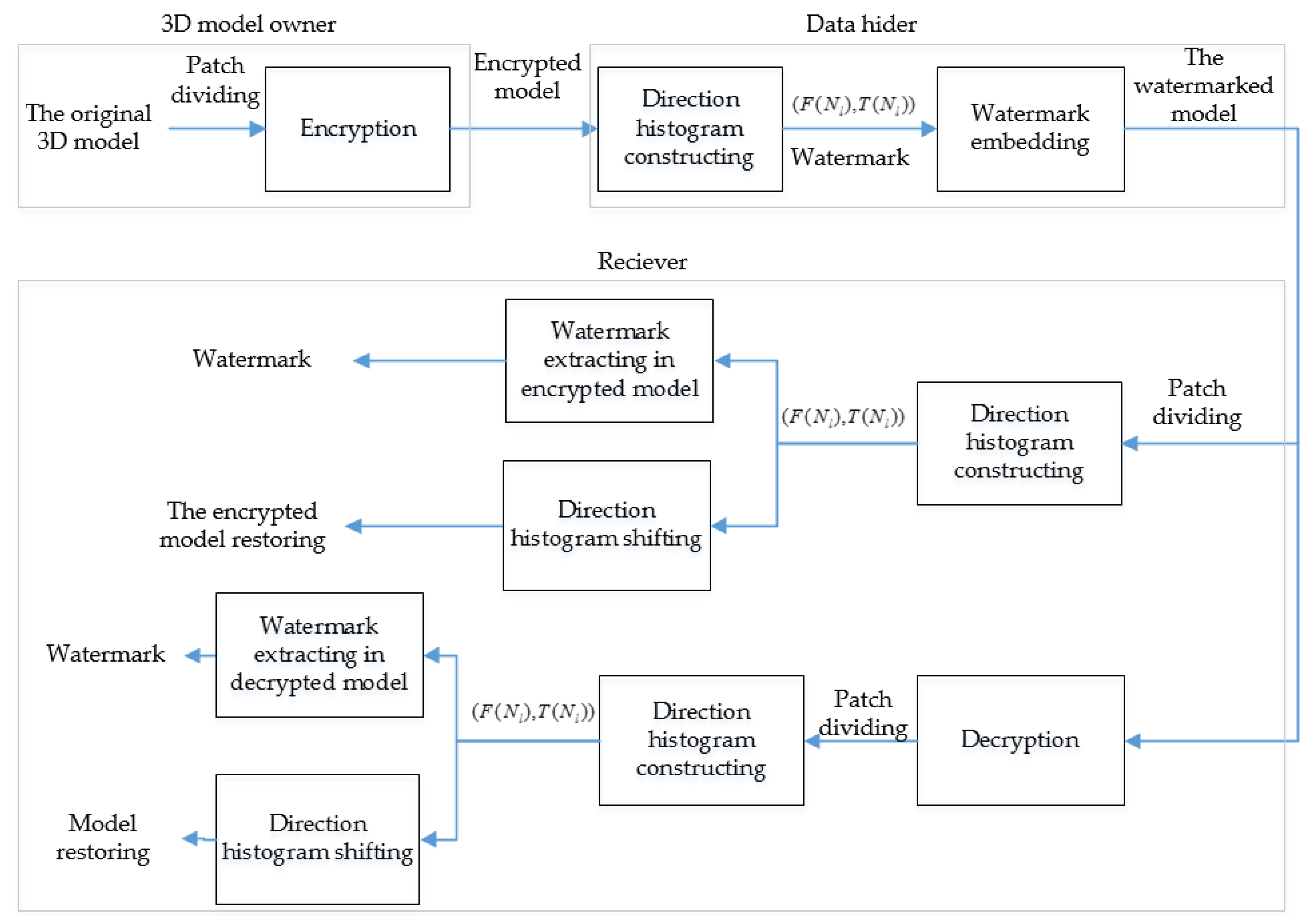
Figure 1 shows the flowchart of the proposed method. Firstly, the original model is divided into patches, and vertices in each patch are encrypted using the Paillier cryptosystem. In the cloud, three direction values of each patch are computed, and the direction histogram is constructed for shifting to embed the watermark. At last, the watermark can be extracted from direction histogram, and the original 3D model can be restored by histogram shifting.
3.1. Preprocessing
Because the input of the Paillier cryptosystem should be a positive integer, the vertex coordinates firstly are converted from decimal to positive integer.
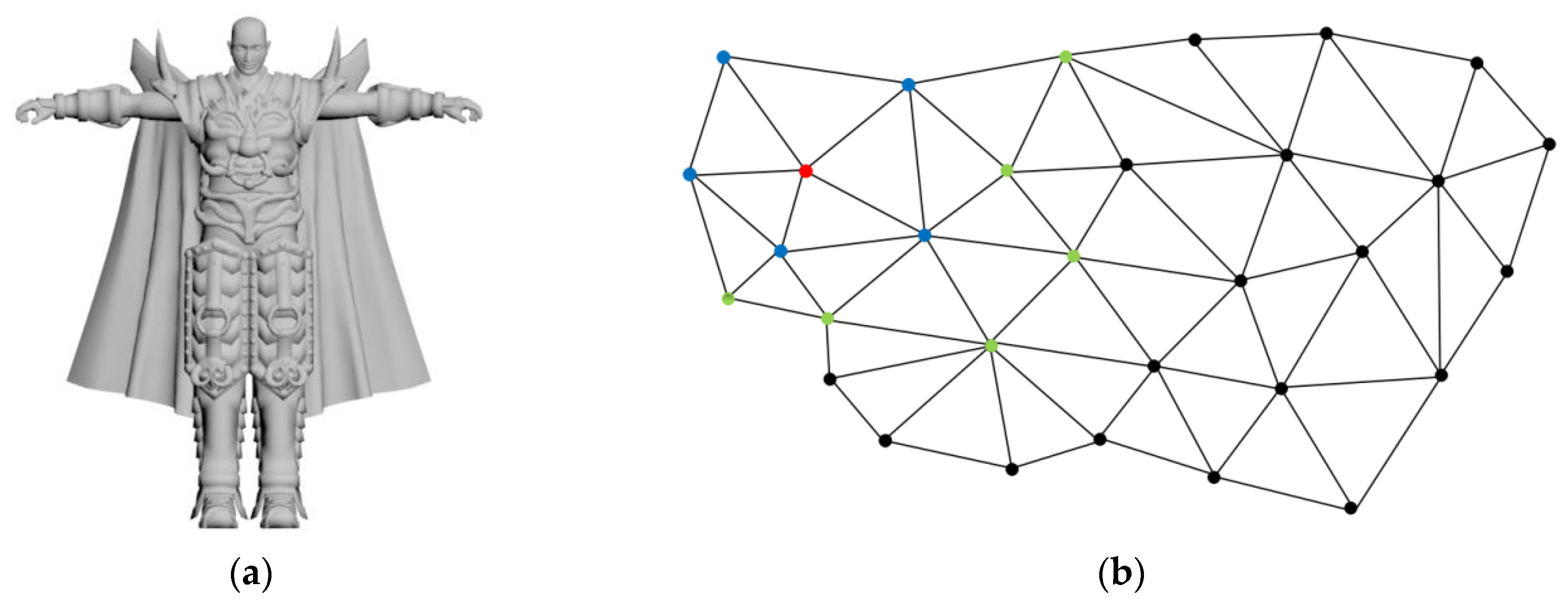
3D models are consisted of vertex data and connectivity data. The vertex data includes the coordinates of each vertex in the spatial domain. The connectivity data reflects the connection relationship between vertices. A 3D model devil and its local region are illustrated in
Figure 2. Each vertex and each face of the 3D model have a corresponding index number, respectively. For a 3D model
, let
represents the sequence of vertices, where
and
is the number of vertices. Note that each coordinate
, and the significant digit of each coordinate is 6.
Normally, uncompressed vertices are 32-bit floating point numbers with a precision of 6 digits. The first four significant digits of vertex coordinates can accurately display the 3D model. Therefore, the vertex coordinates are converted into an integer with four significant digits by using Equation (7).
Moreover, all vertex coordinates should be converted to positive integers for encryption by using Equation (8).
After preprocessing, the pre-processed 3D model is computed, and denoted as .
3.2. Patch Dividing and Patch Encryption
The section describes how to divide the model into several non-overlapping patches and perform encryption by using the Paillier cryptosystem.
3.2.1. Patch Dividing
For the vertex of the 3D model, if two vertices
and
are connected by a edge,
is a neighbor of
. All neighbors of
constitute the 1-ring neighborhood of
, and all 1-ring neighborhood of the neighbors of the vertex
constitute its 2-ring neighborhood.
is the 2-ring neighborhood of the vertex
, and
is computed by
where
are the number of the vertices of the 3D model, and
represents the number of vertices between
and
. As illustrated in
Figure 2, the blue vertices are the 1-ring neighborhood of the red vertex, and the green vertices are the 2-ring neighborhood of the red vertex.
When the 3D model is divided into patches, it is necessary to ensure patches do not overlap each other. Suppose that the unclassified and classified sets are and , respectively. and are initially empty. Suppose that the patch is denoted as . A 3D model is divided into patches by the following rules, and initially .
Step 1: The first vertex
is selected according to the order of vertex index, and
and its 1-ring neighborhood are used as the
. Vertices in
are sorted by
where
is the number of vertices in
.
Step 2: Update the unclassified set and the classified set by using Equation (11).
where
is the union of two sets, and
is the vertex set that exist in
but not in
.
is put into the classified set for ensuring patches do not overlap each other.
Step 3: Determine whether the unclassified set is empty. If is empty, then the division of patches ends. If is not empty, then continue to select the patch from Step 1, until is empty.
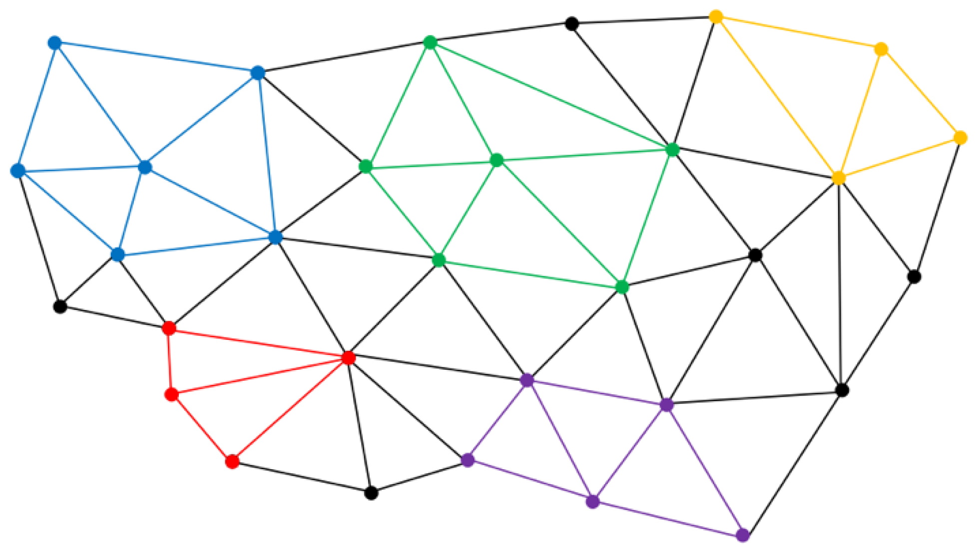
As illustrated in
Figure 3, the local region of 3D model devil can be divided into five patches, and each color in
Figure 3 represents a patch.
3.2.2. Patch Encryption
Let
be the
-axis coordinates of the
vertex in
. Referring to Equation (2), an integer
can be randomly selected to encrypt
with the public key
.
where
,
denotes the encrypted vertex coordinates, and
represents the encrypted model.
3.3. Watermark Embedding
Firstly, three direction values of each patch in ciphertext are computed. Then, according to the possible values of the direction in ciphertext, the mapping table is constructed to map the direction values in ciphertext to the direction values in plaintext. The direction histogram is constructed by counting the direction values of all patches. Lastly, the watermark is embedded by histogram shifting.
3.3.1. Three Direction Values Calculation of Each Patch
In order to calculate three direction values of each patch, a vector
is defined by using Equation (13).
Suppose that
denotes the
-axis direction value of the
patch
, which is calculated by Equation (14).
In the encrypted domain, without the private key
, the encrypted vertex coordinates cannot by decrypted to obtain the vertex coordinate in plaintext, so the direction value
cannot be directly calculated. In the proposed method, the direction value in ciphertext can be calculated using the MMI method.
represents the encrypted patch corresponding to the original patch
. In order to calculate the direction value in ciphertext, the modular multiplicative inverse
of
should be calculated through the extended Euclidean method.
satisfies
For the
patch, the vectors
and
are defined by using Equations (16) and (17), respectively.
Since the direction value
may be negative, two direction values
and
are re-defined. If
is positive,
is the ciphertext corresponding to
. If
is negative,
is the ciphertext corresponding to
.
and
can be calculated by Equation (18).
After
and
are calculated,
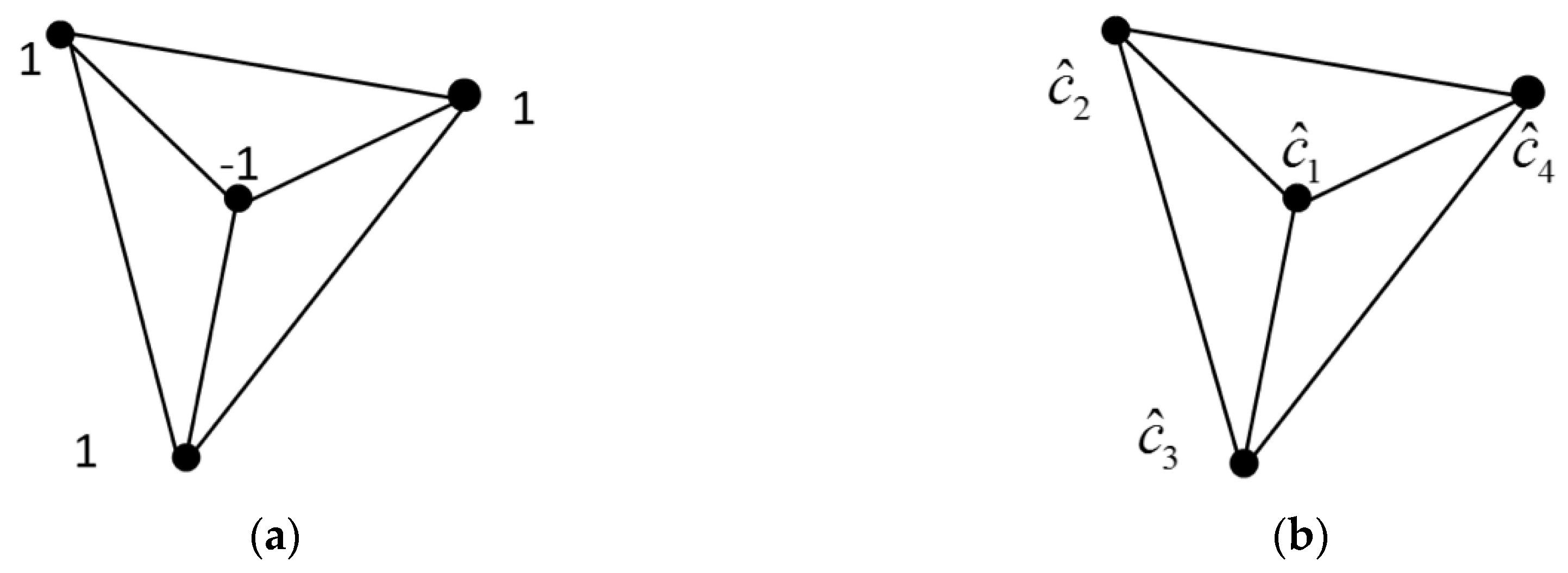
is obtained by querying the mapping table. The following is the corresponding equation derivation and proof. To facilitate understanding, a patch consisting of four vertices is used as an example. Suppose that
denote the
-axis coordinate of the
vertex as illustrated in
Figure 4, and
is the ciphertext corresponding to
.
is the modular multiplicative inverses corresponding to
, which satisfies
Then the direction value in ciphertext can be calculated by using Equation (20).
It can be derived to the following equation.
According to Carmichael theory, the following equation holds.
Hence, the following equation holds.
According to Equations (19) and (23), Equation (24) can be derived.
According to Equations (22) and (24), Equation (20) can be simplified as
3.3.2. Constructing the Mapping Table
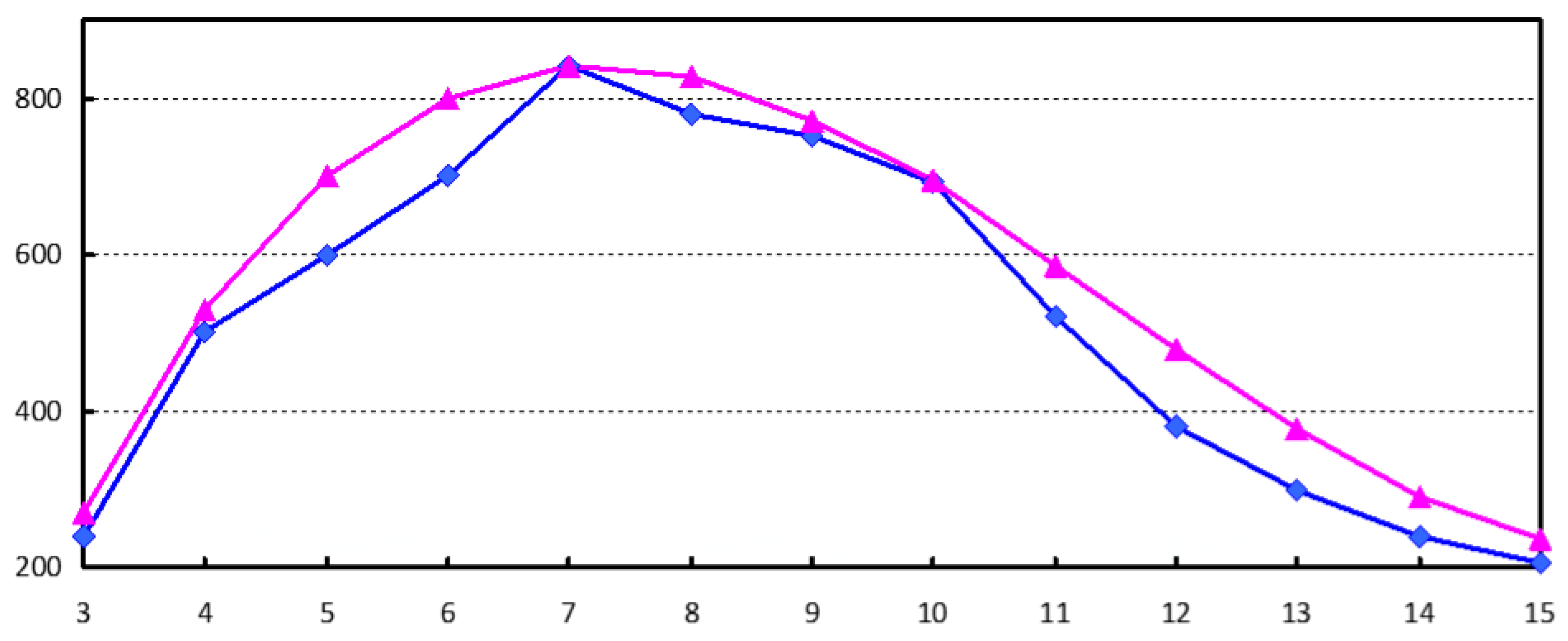
Due to the spatial correlation of the 3D model, the vertex coordinates are relatively close in space. According to the experiments on multiple 3D model, the direction values are usually in a certain range, and the maximum direction value is usually related to the number of vertices in the patch. As illustrated in
Figure 5, the blue line shows the change in the maximum direction value when the number of vertices in the patch changes. The red line is the fitted curve of the blue line, and its fitting function
satisfies
Therefore, the direction values are all within a certain range. When the number of vertices of the patch changes, the direction values does not exceed
. Moreover, in order to obtain robustness, the robust interval
is designed in the process of histogram shifting. The robust interval
is related to the number of the patch, which is defined by
where
represents the strength of robustness. Hence, the change of direction values is
at most.
Suppose that
denotes the absolute of direction values, then
. With the public key, and the ciphertext
corresponding to
can be calculated by
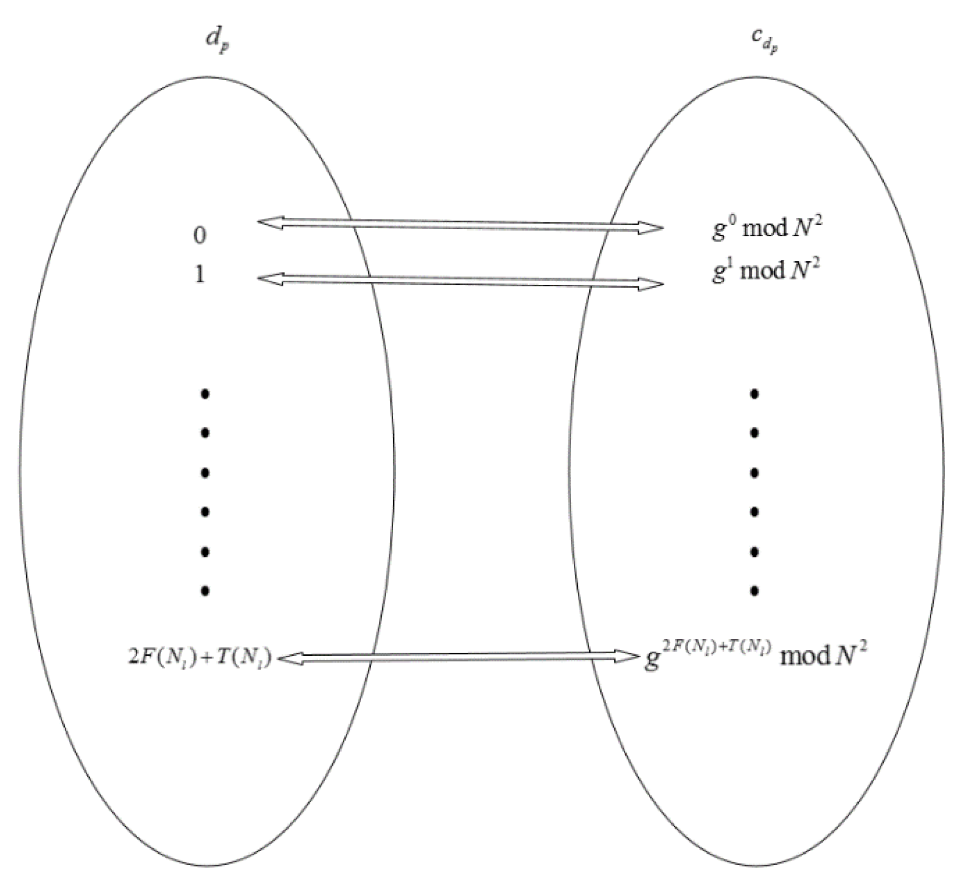
Hence, the mapping table can be constructed as illustrated in
Figure 6, and the direction values in ciphertext can be mapped to the direction values in plaintext through the mapping table
. The mapping method is described as follows:
is a ciphertext set obtained by encrypting all possible values
. When
matches the value
in
, it indicates
, and
. When
matches the value
in
, it indicates
, and
, where
, and
represents the
value in the mapping table. Therefore, without the private key, the direction values in plaintext can be obtained by querying the mapping table.
3.3.3. Constructing the Symmetrical Direction Histogram
In the proposed method, the direction values in ciphertext are first calculated using the MMI method. Then, according to all possible direction values, the mapping table can be constructed, so the direction values in ciphertext can be mapped to direction values in plaintext. Last, the direction histogram can be constructed by counting all direction values. The direction histogram of all patches with six vertices is shown as
Figure 7. It is found that most direction values are concentrated in the central area, and only a small part of the direction values are beyond the central area. Moreover, the direction histogram is symmetrical visually.
3.3.4. Embedding Watermark by Histogram Shifting
In the proposed method, the watermark is embedded by shifting the direction histogram. In order to embed the watermark, the changed direction values should exceed the range of original histogram. Using
and
as embedding keys, the embedded function
is defined by Equation (29) to change the direction values.
where
is the function about
,
will not change, and
means to round up. Suppose that
, and
can be changed by modifying
. Moreover, three bits can be embedded by changing three direction values of a patch. Suppose that
denotes the encrypted patch with watermark. If the watermark bit ‘0′ needs to be embedded, the vertex coordinate is not changed, which means
. If the bit ‘1′ needs to be embedded, the ciphertext
in the patch
is changed by Equation (30) to obtain
.
where
is the encrypted patch with watermark. Suppose that
denotes the decrypted patch with watermark. The operation in ciphertext is equivalent to change the coordinates
to
in plaintext.
Suppose that
denotes the direction value with watermark. After embedding the bit ‘0′,
is still in the range
, so
is called the 0-bit area. After embedding the bit ‘1′,
will be changed by the size of
for making
within the range
or
.
and
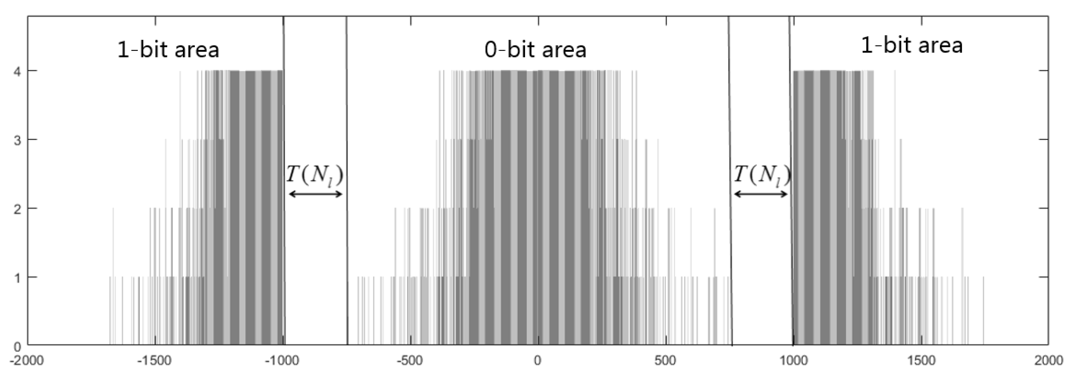
are called the 1-bit area. Finally, the encrypted model with watermark can be obtained. For example, after embedding 1000 bits, the direction histogram is shown in
Figure 8. When embedding the bit ‘0′, the direction values are still in the 0-bit area. When embedding the bit ‘1′, the direction values will be shifted into the 1-bit area. Moreover, the 0-bit area and the 1-area are separated by the robust interval of size
. Hence, the watermark is embedded successfully.
3.4. Watermark Extraction
Watermark extraction includes extracting the watermark in the encrypted model and extracting the watermark in the decrypted model.
3.4.1. Extracting Watermark in an Encrypted Domain and Restore the Original Encrypted Model
The watermarked model is firstly divided into patches, and the direction values in ciphertext is calculated and mapped to the direction values in plaintext using the MMI method and the mapping table. Then, the direction histogram is constructed, and the watermark is extracted from direction histogram. Finally, with the embedding key
, the embedding function
can be obtained to restore the original encrypted model. Let
be the watermark embedded in the
-axis of the
patch, and
is extracted by Equation (32).
The original encrypted model can be restored by histogram shifting, which is reverse to the embedding process. In order to restore the original encrypted model, the modular multiplicative inverse
of
need to be calculated through the extended Euclidean method.
Therefore, the original encrypted vertex coordinate
can be obtained by Equation (34).
where
is the vertex coordinate with watermark in the patch
, and the processing in ciphertext is equivalent to the change in plaintext by using Equation (35).
After the above process, is restored to , and the original encrypted model can be obtained.
3.4.2. Extracting Watermark in Decrypted Model
With the private key, the watermarked model can be decrypted. With the embedding key, the watermark can be extracted and the original 3D model can be restored. Firstly, the watermarked model is divided into patches and the direction values of each patch are calculated by using Equation (14). Then, the direction histogram is constructed and the watermark is extracted from direction histogram by using Equation (32). Finally, with the embedding key, the original model can be restored by using Equation (35).
The decrypted model with watermark may be vulnerable to some common attacks such as noise interference during transmission. Since the robust interval during histogram shifting is reserved, the proposed method is robust to common attacks, such as Gaussian noise, translation, scaling, etc. As illustrated in
Figure 8, the 0-bit area and the 1-bit area are separated by the robust interval of size
. After the decrypted watermarked model is attacked slightly, it will cause a small range fluctuation of the direction values. However, if the direction values do not enter the error area, the receiver can still correctly extract the watermark. In order to improve the accuracy of watermark extraction after being disturbed, the watermark is extracted by using
4. Experimental Results and Discussion
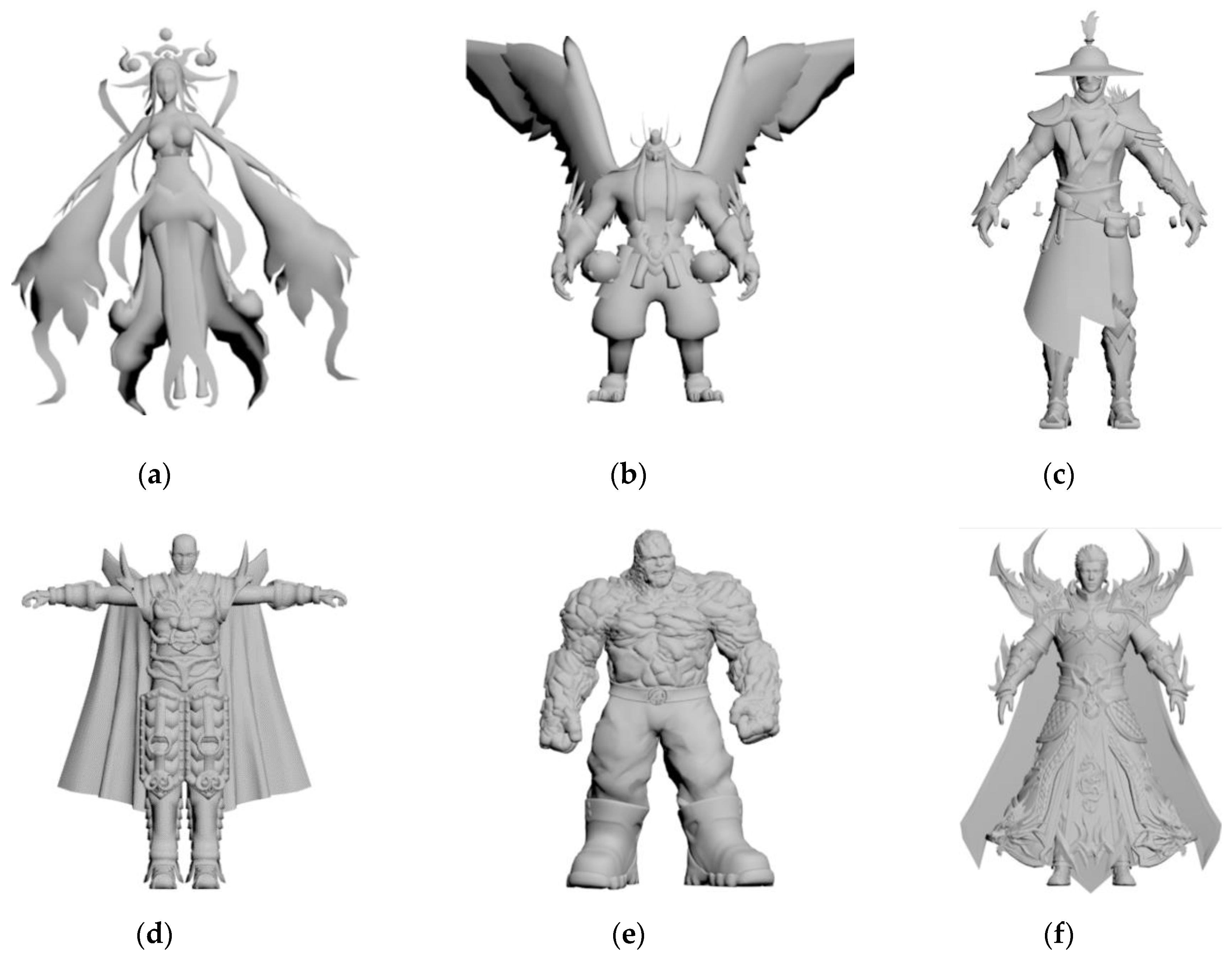
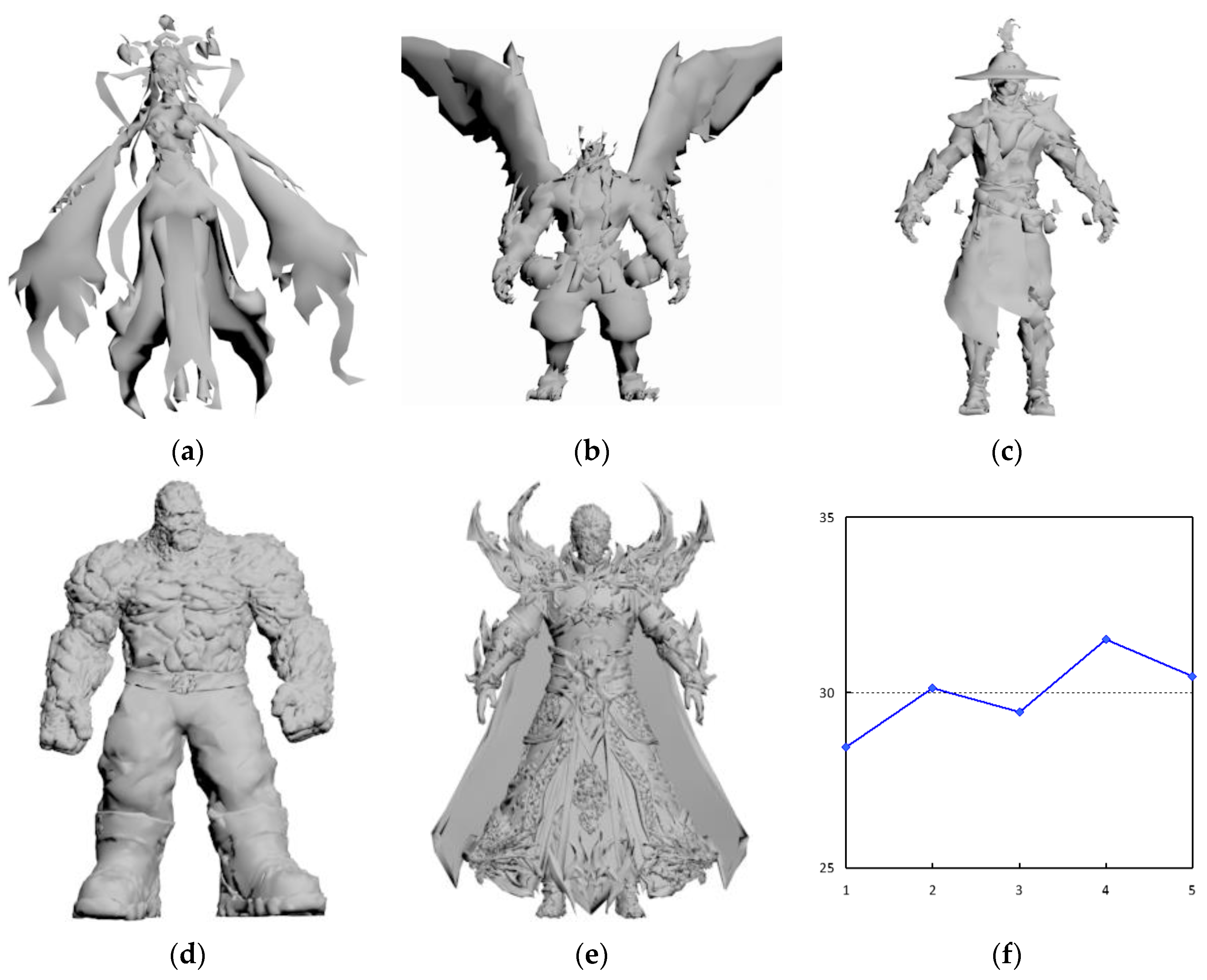
The proposed method processed 3D model and implemented the watermark method in MATLAB R2016b under Window 7. We implemented the following experiment on 40 3D models and calculated the average of 40 3D models.
Figure 9 shows six models used in the experiment.
The quality of the decrypted watermarked model is evaluated by the signal-to-noise ratio (
). The higher the value
, the better the imperceptibility after embedding watermark.
is computed as
where
are the mean of vertex coordinates,
are the original coordinates, and
are the coordinates of the watermarked model
.
In addition, the bit error rate (BER) is used to measure the error rate of the extracted watermark. The lower the value, the higher the accuracy of the extracted watermark.
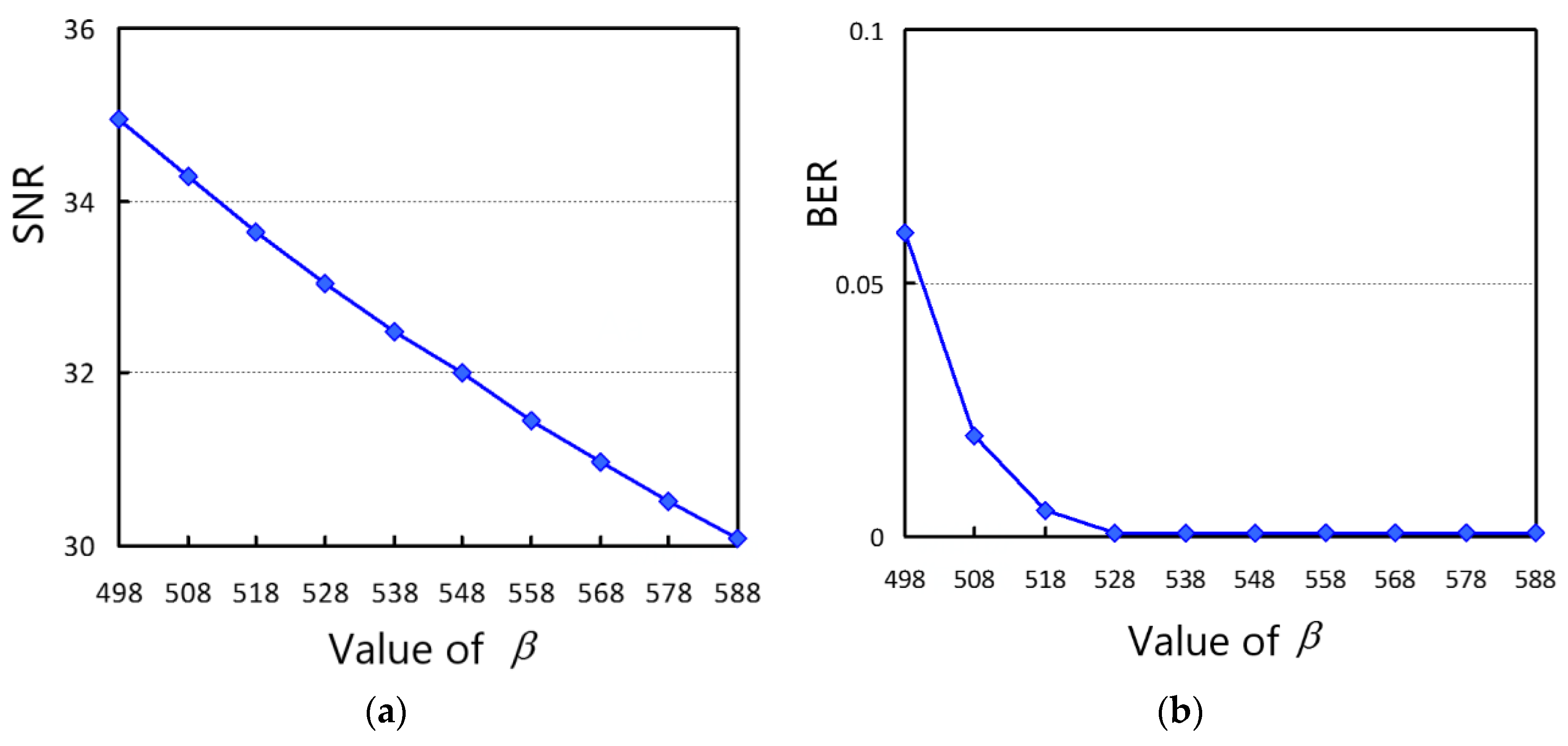
4.1. The Value of
According to Equation (29),
, and the embedding function
is changed by changing the value of
. According to Equation (31), if the value of
is large, the distortion of the decrypted model is high and the accuracy of watermark extracting is high, and vice versa. In order to observe the effect of
on the quality of decrypted model and the bit error rate of the extracted watermark, we changed the value of
to perform on 40 tested models and calculated their average. The relationship between the value of
and the distortion
is illustrated in
Figure 10a. As
increases,
gradually decreases. When
= 588,
of the decrypted model is slightly greater than 30 dB. Based on imperceptible considerations, in order to obtain better model quality, the value of
cannot exceed 588. The relationship between the value of
and BER is shown in
Figure 10b. When
, the watermark was correctly extracted without being attacked. Therefore, the value of b cannot be less than 528.
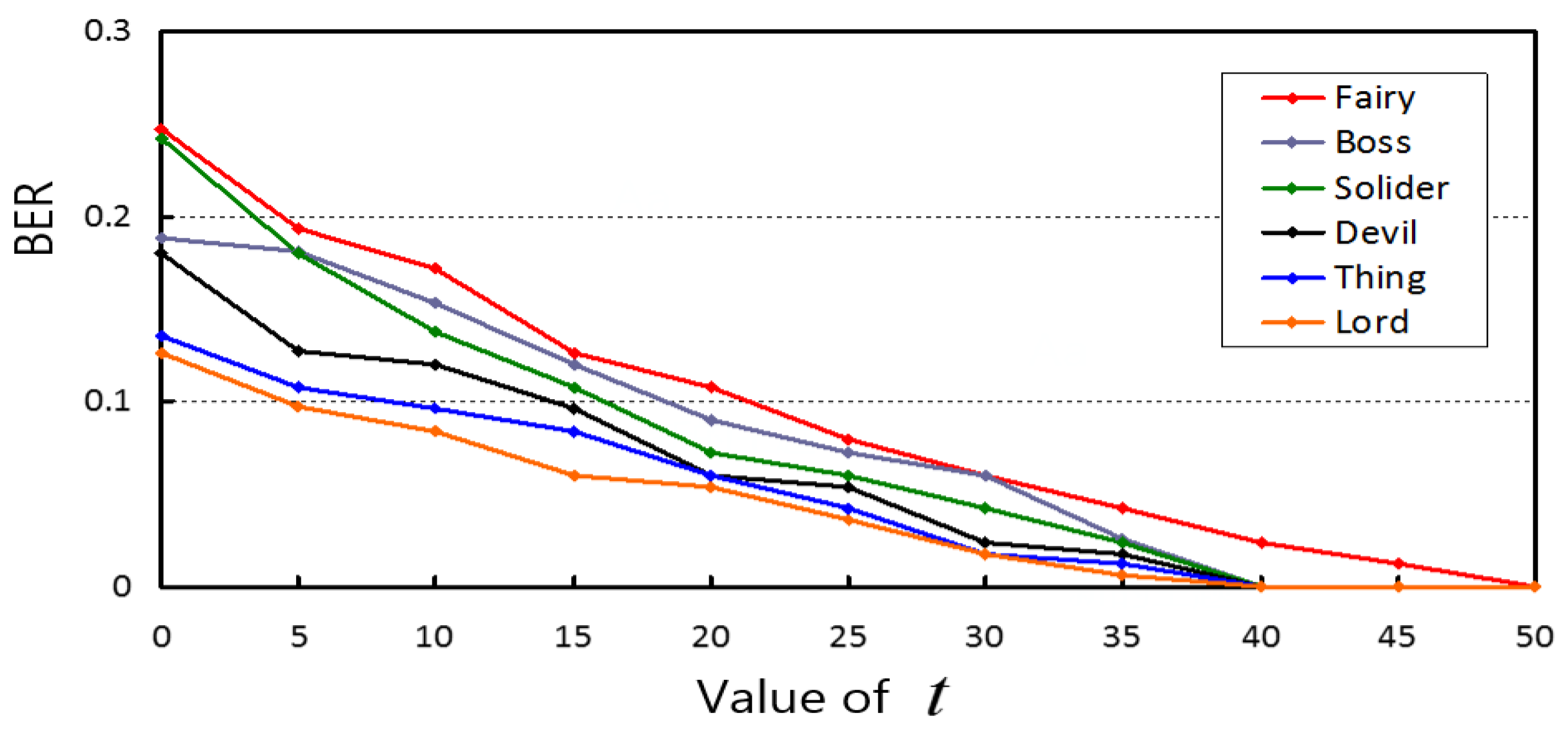
4.2. The Value of
As shown in
Figure 7, the 0-bit area and 1-bit area are separated by the robust interval of size
. If the robust interval is large, the robustness is high. However, as
increases, the quality of the decrypted model is reduced. Therefore,
needs to be adjusted according to the actual application scenario. If higher robustness is required, a greater value of
can be assigned. If better quality of decrypted model is required, a smaller value of
is set. In order to choose a suitable value, experiments were conducted on 40 models to test the robustness with different values of
.
As illustrated in
Figure 11, the BER of watermark extraction is low under Gaussian noise (0.01). By increasing
, the BER could be reduced. When
, the watermark could be extracted correctly. Therefore, when higher robustness is required, the value of
can be assigned to be 50.
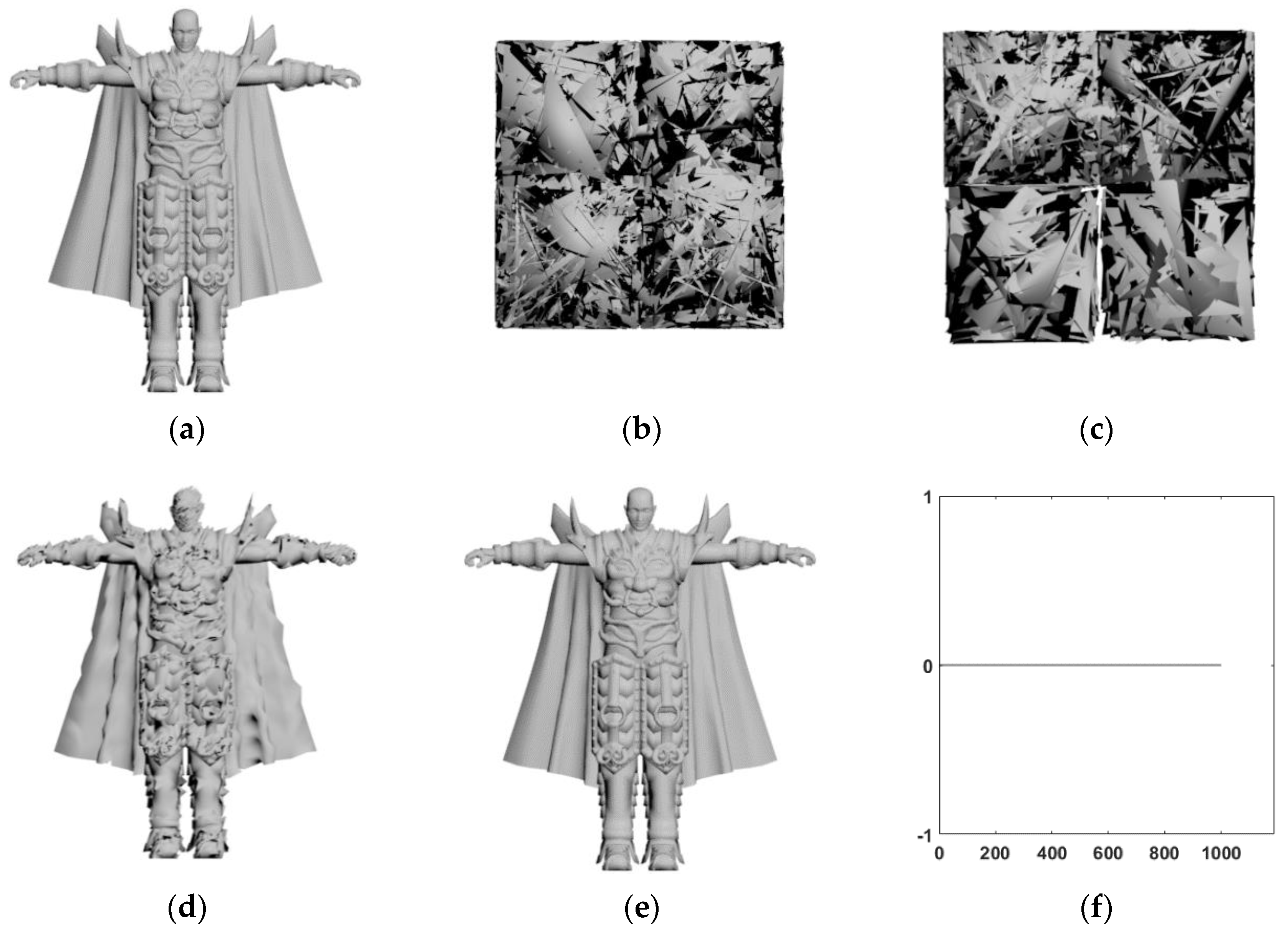
4.3. Feasibility of the Watermarking
In order to show the feasibility of the proposed watermarking method, the 3D model devil with 30,000 vertices was tested, and other models had similar results. The watermark was a 1024-bit pseudo-random sequence. Firstly, the original model was divided into patches and the encrypted model was obtained by encrypting the 3D model with the public key as illustrated in
Figure 12. Secondly, with the embedding key, the watermark was embedded to obtain the watermarked model as illustrated in
Figure 12c. Then, the directly decrypted model (as shown in
Figure 12d) is obtained by decrypting the encrypted model;
of the decrypted model was 30.93. Lastly, the watermark was extracted and the model was restored (as shown in
Figure 12e), and the
of the restored model approaches infinity, which shows that the restored model was exactly the same as the original model.
Figure 12f shows that all watermark bits were correctly extracted. The experimental results showed that the proposed method achieved reversibility of embedding and extraction, and the restoration of the original model.
Figure 13 shows five decrypted 3D models had less distortion compared to the original 3D model, and
Figure 13f shows the
SNR of the decrypted models were close to 30, which denotes the proposed method can obtain good quality.
4.4. Robustness Analysis
In order to compare the robustness under attacks, several attacks were performed on the decrypted 3D model.
Table 1 shows the bit error rate of watermark extraction under different attacks.
4.4.1. Robustness Against Translation Attacks
The robustness against the translation attacks was tested. As shown in
Table 1, the method perfectly resisted translation attacks. When the model was subjected to a translation attack, the vertex coordinates of the patch increased by a certain value at the same time. According to Equation (14), when the vertex coordinates in a patch are changed by the same size, it can be known that its direction values will not change. Therefore, the watermark can be extracted correctly.
4.4.2. Robustness Against Scaling Attacks
The robustness against scaling attacks was tested by different levels (0.8, 1.2, 1.5) on the decrypted 3D model. As shown in
Table 1, the proposed method was robust to scaling attacks. When the model was attacked, the vertex coordinates of the patch were multiplied by a certain coefficient at the same time. According to Equation (14), its direction values also increased or decreased accordingly. As illustrated in
Figure 7, the direction values of most patches were concentrated in the central area. Therefore, when the scaling size was increased, most of the vertices were still in the original area, and only a small number of vertices were offset. On this condition, the robustness was high. When the scaling size was decreased, the 1-bit area was easily shifted to the 0-bit area, which affected the accuracy of extracting the watermark. Therefore, the robustness was much higher when the 3D model was amplified compared with other levels of attacks.
4.4.3. Robustness to Gaussian Noise Attacks
The robustness against Gaussian noise attacks was tested by performing different degrees (0.005, 0.01, 0.02) on the decrypted 3D model. As shown in
Table 1, the robustness against Gaussian noise attacks was high. When the model was attacked by Gaussian noise, the vertex coordinates were slightly disturbed. According to Equation (14), its direction values were also slightly modified. As illustrated in
Figure 7, the direction values of most patches were concentrated in the central area, and only a few vertices were in the non-central area. Therefore, when the model was slightly disturbed, the direction values of the central area were slightly disturbed, and only a few direction values of non-central area were shifted.
However, the proposed method cannot resist the attacks of cropping and simplification, it is because those attacks will influence the order of the vertices. Moreover, the proposed method cannot resist salt and pepper noise, mainly because the attack obviously changes the relative position between vertices.
4.5. Compared with the Existing Watermark Method in an Encrypted Domain
To our knowledge, few effective robust reversible watermarking methods for 3D model in the encryption domain has been reported in the literature. In order to show the effectiveness of the proposed method, Jiang [
1] is extended to the encrypted 3D model. From
Table 2, the proposed method has a slightly higher embedding capacity compared with the Jiang [
1], and it is mainly because a patch has three coordinate axes and three bits can be embedded. To sum up, the proposed method has good security and robustness, and the decrypted 3D model has low distortion.
5. Conclusions
In this paper, a robust reversible three-dimensional (3D) model watermarking method based on homomorphic encryption is presented for protecting the copyright of 3D models. The 3D model is divided into non-overlapping patches, and the vertex in each patch is encrypted by using the Paillier cryptosystem. On the cloud side, three direction values of each patch are computed, and the symmetrical direction histogram is constructed for shifting to embed watermark. In order to obtain robustness, the robust interval is designed in the process of histogram shifting. The watermark can be extracted from the direction histogram, and the original encrypted model can be restored by histogram shifting. Experimental results show that the decrypted 3D models have less distortion compared with the existing methods, which denotes the proposed method can embed more secret data without increasing the 3D models distortion. Moreover, the proposed method can resist a series of attacks compared to the existing watermarking methods on encrypted 3D model. Thus, the proposed method is efficient to protect copyright of 3D models in the cloud when the cloud administrator does not know the content of the 3D models, but the existing methods have no ability.
In the future, we will investigate the following two possible research directions. (1) Reduce the distortion of the directly decrypted 3D model. (2) Further improve the robustness against more kinds of attacks, such as cropping and salt and pepper noise.


