Article

Rayleigh-Bénard Convection of Paramagnetic Liquid under a Magnetic Field from Permanent Magnets

Department of Mechanical Engineering, Osaka Prefecture University, 1-1 Gakuencho, Naka-ku, Sakai 5998531, Japan
*
Author to whom correspondence should be addressed.
Symmetry 2020, 12(3), 341; https://doi.org/10.3390/sym12030341
Submission received: 30 January 2020 / Revised: 18 February 2020 / Accepted: 24 February 2020 / Published: 28 February 2020
(This article belongs to the Special Issue Symmetry in Fluid Flow)

Abstract

:
The convection control is important in terms of the heat transfer enhancement and improvement of the applied devices and resultant products. In this study, the convection control by a magnetic field from block permanent magnets is numerically investigated on the Rayleigh-Bénard convection of paramagnetic fluid. To enhance the magnetic force from the available permanent magnets, pairs of alternating-pole magnets are employed and aligned near the bottom heated wall. The lattice Boltzmann method is employed for the computation of the heat and fluid flow with the consideration of buoyancy and magnetothermal force on the working fluid. It is found that, since the magnetic force at the junction of pair magnets becomes strong remarkably and in the same direction as the gravity, descending convection flow is locally enhanced and the pair of symmetrical roll cells near the magnet junction becomes longitudinal. The local heat transfer corresponds to the affected roll cell pattern; locally enhanced at the magnet junctions and low heat transfer area is shifted aside the magnet outer edge. The averaged Nusselt number on the hot wall also increases proportionally to the magnetic induction but it is saturated at high magnetic induction. This suggests the roll cell pattern is no more largely affected at extremely-high magnetic induction.

Graphical Abstract

1. Introduction

The natural convection is the buoyancy-driven flow and has been widely observed in nature and engineering fields. The natural convection heat transfer is dominated by the physical properties of the working fluid such as the viscosity and the density depending on temperature or concentration (if multicomponent fluid). It is also affected by the enclosure size and configurations, the heating and cooling conditions (uniform wall temperature, constant heat flux at the wall, periodic change of temperature or heat flux, etc.). The convection has laminar and turbulent flow regimes depending on the above parameters. The representative governing dimensionless parameters which characterize the convection are the Prandtl number Pr = ν/a and Rayleigh number R a = g β Δ θ 3 / a ν where ν is the kinematic viscosity, a is the thermal diffusivity, β is the volumetric expansion due to the temperature θ or concentration, is the characteristic length. Generally, as Ra increases, the convection becomes strong and the flow is shifted from the laminar to the turbulent natural convection. In a small-sized container such as microfluidics, the convection is in the laminar regime as recognized by the small Ra.
Rayleigh-Bénard convection (RBC) is one of representative natural convections. The convection is induced inside confined lateral heated bottom and cooled top plates in the gravity field. RBC has symmetrical roll cells in an ideal situation; a pair of clockwise and anti-clockwise cells are aligned. As aforementioned, the characteristic of heat transfer depends on Pr and geometrical confinement at the same Ra [1]. The large-scale atmospheric circulation is in turbulent regime and its structure has been studied [2]. The earth’s outer core convection is large Ra and high Pr RBC with rotation and chemical reaction [3]. In the engineering field, RBC can be observed in single silicon crystal manufacturing process by Czochralski method [4]. For the convection control, controlled by the feedback control of heat flux [5], rotation and magnetic field [6,7], external forces such as the electromagnetic force [4,8], electric force [9], etc., has been reported. The controlling force induced in the working fluid depends on the physical properties of working fluid.
In this study, the magnetic force is employed to control the convection of the paramagnetic fluid. The paramagnetic material such as air and oxygen can be attracted to magnetic poles. The magnetic force depends on the magnetic susceptibility (physical property) and the local gradient of squared magnetic induction [10]. The magnetic susceptibility depends on the inverse of absolute temperature. In other words, magnetic force on the paramagnetic fluid depends on the temperature. The application of this force has been intensively studied since the strong magnetic induction is available, such by superconducting magnets. In recent studies, the magnetic force on the air (paramagnetic fluid) filled in a porous enclosure is numerically investigated [11]. The magnetic force on the air is numerically applied to the oxygen sensor [12]. The flow structure under a strong magnetic field at low Reynolds number flow is numerically investigated [13].
The Rayleigh-Bénard convection of the paramagnetic fluid under a strong magnetic field has been reported. Braithwaite et al. [14] experimentally investigated that the heat transfer of RBC depends on the relative elevation of RBC enclosure inside the magnet bore of a superconducting magnet. Since then, the evaluation, clarification and application have been conducted by various researchers. Maki et al. [15] experimentally and numerically studied RBC inside the bore of a superconducting magnet with inclination. They further studied and introduced the magnetic Rayleigh number to clarify the characteristics near the onset of RBC [16]. Tagawa et al. [17] extended the magnetic force to a diamagnetic fluid, water. Weiss and Ahlers [18] reported the RBC of nematic liquid crystal inside a solenoid. However, most of these studies presume magnetic fields from superconducting magnet. It is too expensive for the convection control thus, the application is limited to the high-value materials [16,18].
Recently, the application of permanent magnets to control the convection of the paramagnetic fluid has been reported. The effect can be expected when a large magnetic gradient occurs. Indeed, the effect of a single block permanent magnet on the natural convection along a vertical heated wall was numerically investigated by our group [19]. In the literature, the heat transfer can locally enhance and suppress the natural convection near the magnet edge. This phenomenon has also been found by their experiment [20]. Besides, it reported that two magnets paired by alternate poles can induce a remarkable magnetic force at its junction in the normal direction to the magnet. This implies that, if this force is in the same direction as the gravity, the enhancement/suppression of the natural convection can be expected. Fortunately, when the magnets are placed at the bottom/top wall of RBC, the dominant magnetic force is in the same direction as the gravity. In that point of view, the effect of the magnetic field by paired permanent magnets on the RBC is numerically investigated.

2. Computational Methods

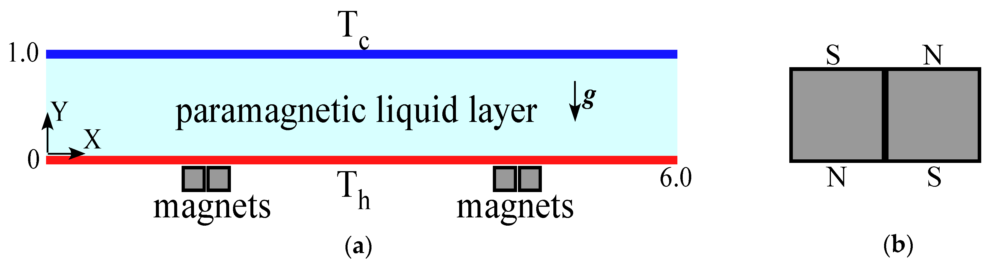
2.1. Schematic Model

In this study, two-dimensional numerical simulations are carried out for Rayleigh-Bénard convection in the presence of a magnetic field. The schematic model for the computation is shown in Figure 1a. The paramagnetic liquid layer is confined by two horizontal plates. The bottom plate is heated at non-dimensional temperature of Th (=2.0) and top plate is cooled at Tc (=1.0), both isothermally. Sidewalls of the computational domain are considered as the periodic boundary for the simplicity. In the presence of the gravity, the working fluid is driven by buoyancy.
The magnetic field applied to the working fluid is induced by two pairs of two block magnets. Each magnet has square cross section. Two magnets are paired by alternate poles as shown in Figure 1b. Each pair is placed below the heated wall where the descending flow is observed in the absence of the magnetic field.

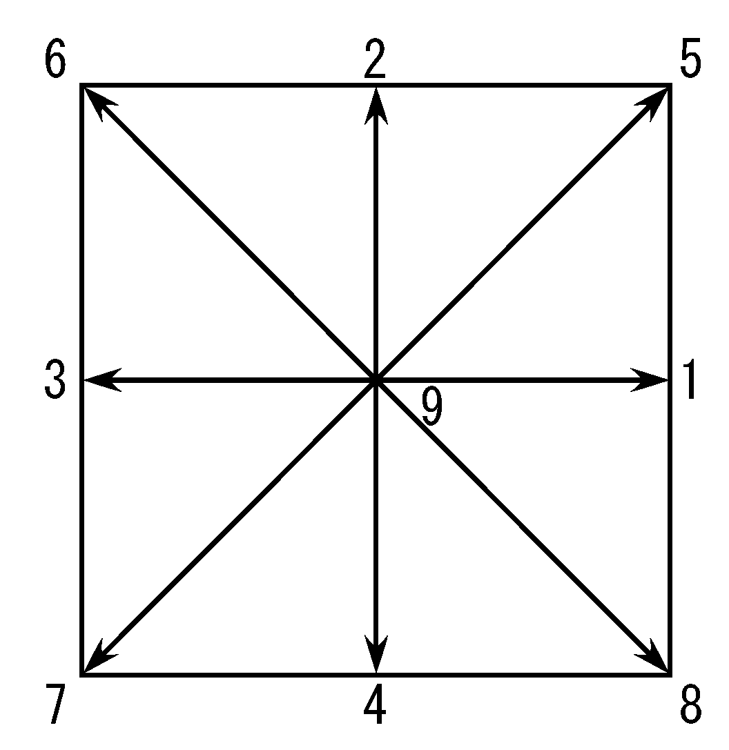
2.2. Lattice Boltzmann Heat and Fluid Flow Simulation

The heat and fluid flow of the working fluid is simultaneously solved by the lattice Boltzmann method (LBM). LBM contains the collision and streaming steps of distribution function explicit in time. This has been under a spotlight due to its flexibility of the physical boundary and parallelization. In this study, two-dimensional nine-discrete velocity (D2Q9) model shown in Figure 2 is employed. CUDA Fortran code is developed for fast computation.
Two distribution functions are respectively employed for the density and thermal energy to obtain the fluid flow and temperature distribution. Note that LBM is generally described by non-dimensional form. Thus, parameters and macroscopic values used in the LBM are non-dimensional.
The time evolution Equations at the lattice site x = (X, Y) and time t are below.
f ^ α ( x + e α δ t , t + δ t )   f ^ α ( x , t ) = S ^ α i   ( f ^ i   f ^ i e q ) + F ^ α 1 2 S ^ α i   F ^ i
g α ( x + e α δ t , t + δ t ) g α ( x , t ) = 1 τ c [ g α ( x , t ) g α eq ( x , t ) ]
The density distribution function f is solved by multi-relaxation-time (MRT) LBM and single-relaxation-time BGK model is applied to the energy distribution function g. The superscript Equation is the equilibrium state.
f α eq = ω α ρ [ 1 + e α u c s 2 + ( e α u ) 2 2 c s 4 u u 2 c s 2 ]
g α eq = ω α T [ 1 + e α u c s 2 ]
The discrete vector is eα. τc is the relaxation time of g. In the density distribution function (Equation (1)), external force term Fα is added [21,22]. In the preset study, the force term contains buoyancy Fb and magnetothermal force Fm.
F α = ω α c s 2 [ ( e α u ) + ( e α u ) c s 2 e α ] ( F b + F m )
where, the buoyancy force is defined by the temperature deviation from the conductive state,
F b = ρ β { T [ T h ( T h T c ) Y ] } g
where β represents the volumetric expansion rate due to temperature.
The magnetothermal force depending both on the temperature and local magnetic induction is as follows.
F m = ρ β χ mm 0 2 μ 0 C { T [ T h ( T h T c ) Y ] } b 2
where μ0 is the magnetic permeability in vacuum, χmm0 is the mass magnetic susceptibility at the reference temperature T0, and ρ the density. In the above equation, the constant C is defined as follows.
C = ( 1 + 1 β T 0 )
The reference temperature T0 in Equation (8) is presumed at 293.15 K. The computational dimensionless numbers are the Prandtl number Pr, the Rayleigh number Ra, and the dimensionless magnetic induction γ. Definitions of these parameters are as follows.
R a = g β Δ T 3 a v
The parameter γ is followed by [23].
γ = χ mm 0 b 0 2 μ 0 g
The buoyancy force works due to temperature difference (Boussinesq approximation). The magnetothermal force depends not only on the magnetic induction but also on the magnetic susceptibility which depends on the temperature since the magnetic susceptibility of the paramagnetic fluid depends on the inverse of the absolute temperature.
The macroscopic parameters are related to the distribution functions as follows.
ρ = α f α
ρ u = α e α f α + δ t 2 F α
P = c s 2 ρ
ν = c s 2 ( τ f 1 2 ) δ t
T = α g α
a = c s 2 ( τ c 1 2 ) δ t
where τf represents the relaxation time used in Equation (1). The computational dimensionless parameters are as follows. The Prandtl number is fixed at 13.0 which corresponds to the gadolinium nitrate aqueous solution of 15.5 wt. % which is the same fluid of [20]. The Rayleigh number is fixed at 104 which corresponds to the temperature difference ΔT of 0.415 K when the gap between hot and cold is presumed at 10 mm. The dimensionless applied magnetic induction γ is varied from 0 to 10.0. For the reference, γ = 1.0 corresponds to 1.01 Tesla by employing the same characteristic length as temperature. Please note that γ = 10.0 is out of available magnetic induction by commercial permanent magnets.
The grid dependency test is carried out prior to the simulation under the magnetic field. The average Nusselt number on the hot wall at Ra = 104 is evaluated by the domain resolutions of 300 × 52, 600 × 102, and 900 × 152 with uniform mesh. The resulted average Nusselt number on the hot wall is 2.6168 (300 × 52), 2.6175 (600 × 102), and 2.6177 (900 × 152), respectively. The reference value of the average Nusselt number at Ra = 104 is 2.661 [24]. RBC by LBM [25] has similar value. Therefore, grid resolution of 600 × 102 nodes is employed both for the computational time and precision.
For the initial condition, the fluid is stagnant and the thermal conductive state is presumed. To induce the natural convection, a small perturbation of temperature is applied at the center of the computational domain. The computations converge and the steady state convection is obtained in all cases.

2.3. Magnetic Field Simulation

The magnetic field employed in this study is numerically obtained by using a free software, FEMM. This can solve the static magnetic field in two-dimensional system by finite element method. In the present study, the static magnetic field from the pair magnet (Figure 1b) is obtained and then remapped in the Cartesian mesh used in the lattice Boltzmann method. For the reference, magnetic fields induced by a single magnet and the pair magnet are shown in Figure 3. As indicated by color, the magnetic field becomes strong at the magnet edge of single magnet (Figure 3a) and stronger magnetic induction at magnet junction of pair magnet (Figure 3b). This suggests that the magnetic force component ∇b2 is also enhanced at the magnet junction due to a large value of |b| in a small area.

3. Results and Discussion

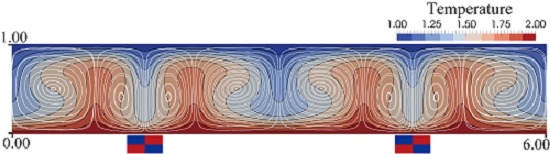
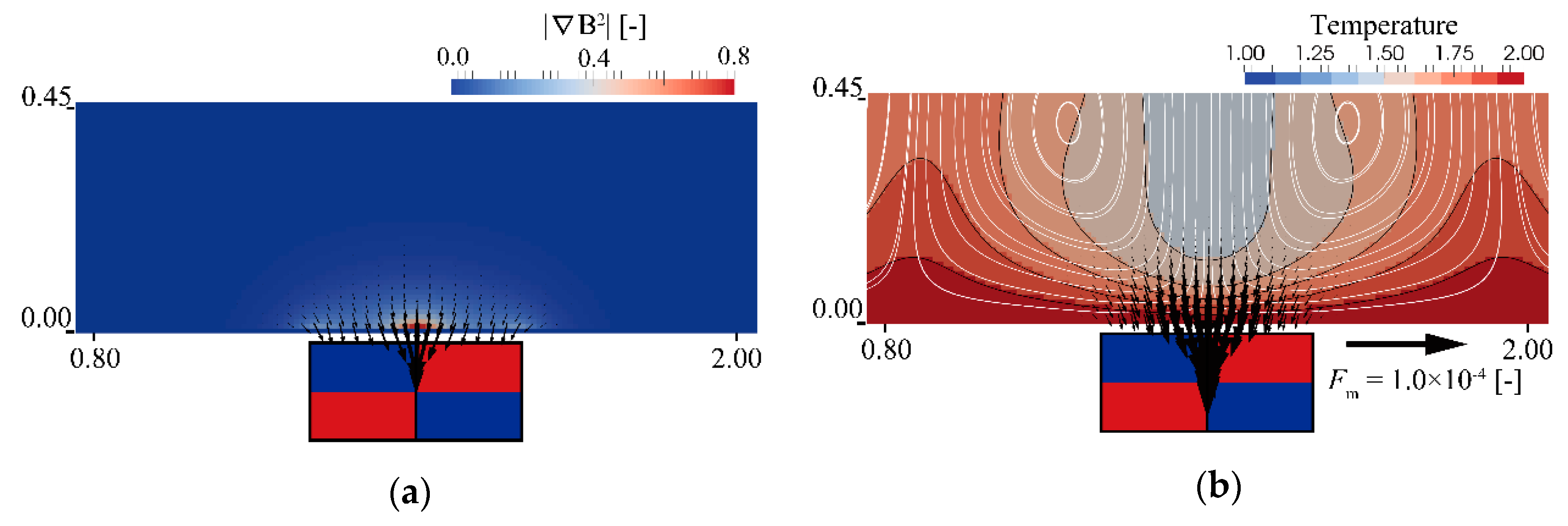
3.1. Heat and Fluid Flow with and without Magnetic Field

Figure 3 shows streaklines and isotherms with and without the magnetic field at Ra = 104. Since the results are symmetric regardless of the magnitude of γ, left half of figures (0 ≤ X ≤ 3.0) are extracted. When the magnetic field is absent (Figure 4a), the flow pattern becomes symmetrical and corresponding temperature field is formed. This is the typical phenomenon of RBC.
When the magnetic field is applied, the cell pattern is shifted depending on applied magnet induction. Figure 4b–d shows the result with the magnetic field of γ = 1.0, 5.0 and 10.0. It is found that the circulation cell near the magnet becomes thinner. In contrast, cells away from the magnet are stretched in horizontal direction. Additionally, the thermal boundary layer near the magnet junction becomes thinner.
The additional external force applied on the working is the magnetothermal force, thus the effect of the force on the heat and fluid flow is discussed in Figure 5. As Figure 3 suggested, Figure 5a shows a strong ∇b2 induced near the magnet junction toward the magnet as reported by our group [20]. As suggested in Equation (7), the magnetothermal force is resulted from the multiplication of ∇b2 and temperature difference. When the cold fluid descends near the magnet junction, the local temperature difference becomes large near the magnet, then the magnetothermal force becomes remarkable as shown in Figure 5b–d. This induced force overlaps the gravity and accelerates the downward flow near the magnet junction, resulting in the locally-enhanced convection. Indeed, as the dimensionless magnetic induction γ increases (Figure 5b–d), the magnitude of the force becomes large and the symmetrical circulating flow is shifted toward the magnet. Due to the strong attracting force toward the heated wall, the working fluid near the junction receives more heat than the other area of the hot wall. Therefore, the upward buoyant flow emerges as soon as the fluid escapes from the magnetic force near the side of the pair magnet. This results in the roll cell thinning as observed in Figure 4. To compensate the roll cell thinning near the magnet, the cells away from the magnet are stretched horizontally.
These symmetric results are not only by the symmetry of the magnetic force but also the direction of the gravity force. When the gravity is normal to the dominant magnetic force, the combined convection due to gravitational and magnetic forces is no longer symmetric [19,20].

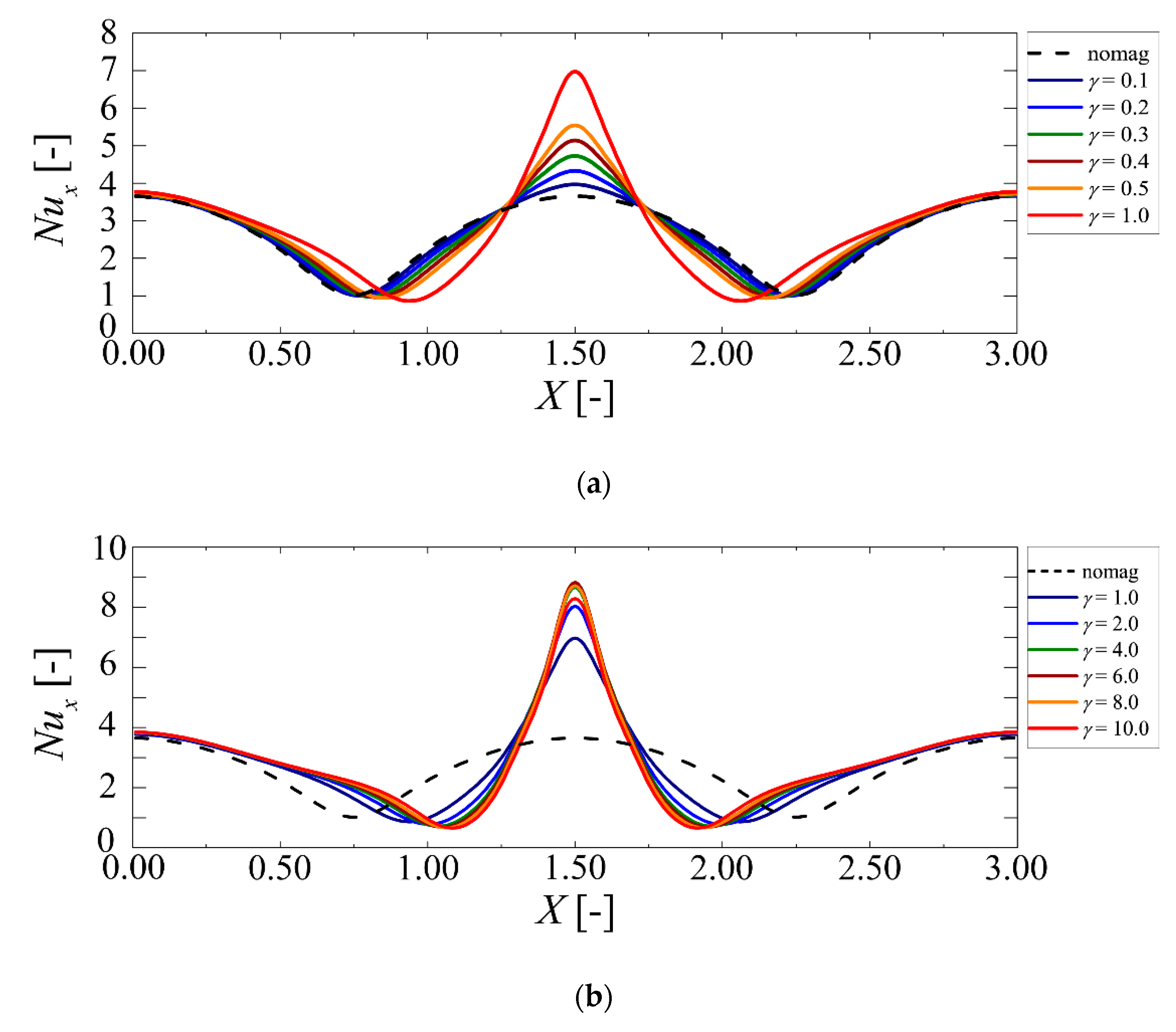
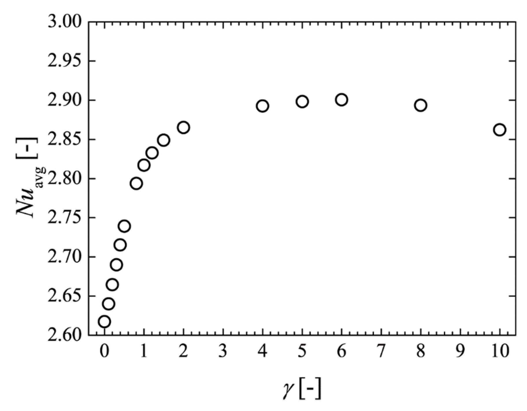
3.2. Effect on Heat Transfer

The magnetic force on the fluid affects the convection cell pattern and thermal boundary thickness near the magnet junction. This can bring local heat transfer enhancement/suppression on the hot wall. The local heat transfer on the heated wall is evaluated by the Nusselt number defined by the following Equation.
N u | x =   d T h o t | x dy / Δ T H
This represents the ratio of the convective heat transfer to the conductive heat transfer. The estimated local Nusselt number profiles at γ = 0–10.0 are summarized in Figure 6. Same as in Figure 4, left half of the computational domain is shown herein. In Figure 6a, as expected, the convective heat transfer is locally enhanced at the magnet junction with the increase of the dimensionless magnet induction γ. Accordingly, the local minima of the Nusselt number is shifted to the magnet junction due to the thinning of the roll cell shown in Figure 4. Interestingly, the symmetry of the profile is kept since the magnets’ location is symmetrical in the computational domain.
In contrast, in Figure 6b, the change of the local Nusselt number by increasing γ becomes small. Contrary to expectations, the peak value decreases from γ = 6.0 to 10.0 and even the magnetothermal force becomes stronger as Figure 5c,d suggest. The reason of the decline of peak value can be understood by the flow field and temperature profile near the magnet. As γ increases, the roll cells near the magnets are thinned. Correspondingly, the cell center position shifts from the mid height of the domain to the hot wall. In other words, the circulation flow near the magnets is stuck near the hot wall. The upward heated flow emerging the side of the magnets is pulled back immediately. This results in the temperature rise above the magnet and thermal boundary thickening. Indeed, comparing Figure 5d with Figure 5c, hotter fluid zone is formed above the magnet junction.
These results suggest that the optimized magnetic induction exists for the maximum heat transfer by the magnetic field. Thus, the total contribution to the heat transfer in the system is investigated by the average Nusselt number on the hot wall.
Figure 7 shows the average Nusselt number on the hot wall versus the dimensionless magnetic induction. As shown in the figure, the average Nusselt number increases corresponding to the magnet induction linearly at γ ≤ 1.0, then it saturates around γ = 6.0. As the induction increases further, it gradually decreases by the aforementioned mechanism.

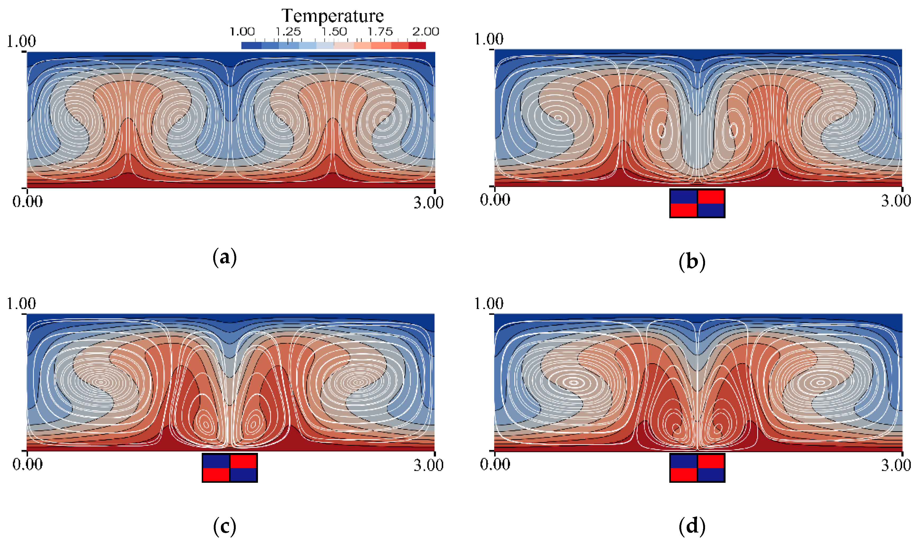
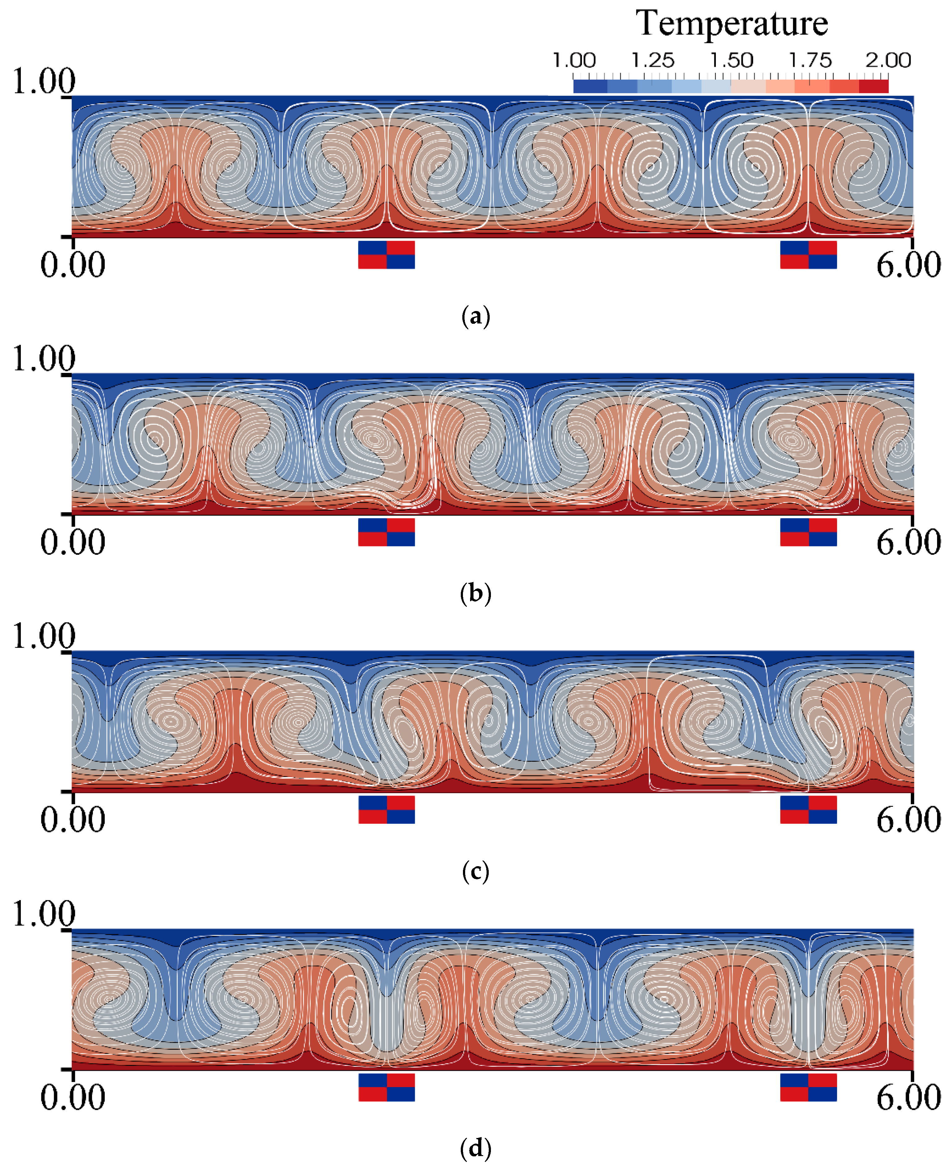
3.3. Roll Cell Shifting by Magnet Location

In the prior sections (Section 3.1 and Section 3.2), the magnet locations were set where the downward flow was observed without magnetic field. This is because the attracting magnetic force on the cold paramagnetic fluid can accelerate the descending flow. Indeed, the descending convection flow near the magnet locally enhances the heat transfer from the hot wall.
The next question is whether this effect is independent of the magnet location. A sample computation is carried out at the different magnet location (shifted +75 nodes to right) where the upward flow is observed without the magnetic field as shown in Figure 8a. Thus, the simulation is started from the steady state convection at Ra = 104 without the magnetic field (same as Figure 4a). A series of snapshots is shown in Figure 8b–d. Interestingly, relatively cold fluid at the bottom of the magnet junction is pulled toward the junction, and then the roll cells are shifted towards it. Consequently, the descending flow is shifted to the magnet junction and correspondingly, the roll cells are shaped. Finally, the heat and fluid flows attain the steady state convection. This is also due to the periodic boundary condition at the sidewalls of the computational domain. Although this is an ideal situation, these results suggest that a locally strong magnetic field can control the position of the convection cells.

4. Conclusions

In this study, the effect of the magnetic field from pairs of permanent block magnets are numerically investigated on the Rayleigh-Bénard convection of the paramagnetic liquid. The pair magnet can induce strong magnetic induction rather than the single one and the magnetic force is directed normal to the magnet junction. When this magnetic force is applied to the fluid in the same direction of the gravity, that is, the horizontal pair magnets are settled below the hot wall, the resulted magnetothermal force locally enhances the descending convection flow. This results in the local heat transfer enhancement corresponding to the magnetic induction. This effect saturates at an extremely strong magnetic field, probably due to the increase of the friction among roll cells. It is also found that this effect is independent of the magnet position. The resultant downward flow is shifted to the magnet junction. This can be applied to the on-demand local heat transfer control for the small heat exchanger, etc.

Author Contributions

Conceptualization, M.K.; methodology, M.K.; software, K.W.; validation, K.W.; investigation, M.K., K.W. and K.S.; data curation, K.W.; writing—original draft preparation, M.K.; writing—review and editing, M.K.; visualization, K.W.; supervision, M.K.; project administration, K.S.; funding acquisition, M.K. All authors have read and agreed to the published version of the manuscript.

Funding

This research was funded by MINISTRY OF EDUCATION, CULTURE, SPORTS, SCIENCE AND TECHNOLOGY-JAPAN, Grant-in-aid for Scientific Research (C) No. 18K03988.

Acknowledgments

The authors would like to thank M. Sugimoto for technical assistance with the simulation.

Conflicts of Interest

The authors declare no conflict of interest.

References

  1. Chong, K.L.; Wagner, S.; Kaczorowski, M.; Shishkina, O.; Xia, K.Q. Effect of Prandtl number on heat transport enhancement in Rayleigh-Bénard convection under geometrical confinement. Phy. Rev. Fluids 2018, 3, 013501. [Google Scholar] [CrossRef] [Green Version]
  2. Pandey, A.; Scheel, J.D.; Schumacher, J. Turbulent superstructures in Rayleigh-Bénard convection. Nat. Commun. 2018, 9, 1–11. [Google Scholar] [CrossRef] [PubMed] [Green Version]
  3. Bouffard, M.; Choblet, G.; Labrosse, S.; Wicht, J. Chemical convection and stratification in the earth’s outer core. Front. Earth Sci. 2019, 7, 1–19. [Google Scholar] [CrossRef]
  4. Grants, I.; Gerbeth, G. Rayleigh-Bénard instability of Czochralski configuration in a transverse magnetic field. J. Cryst. Growth 2012, 358, 43–50. [Google Scholar] [CrossRef]
  5. Howle, L.E. Control of Rayleigh-Bénard convection in a small aspect ratio container. Int. J. Heat Mass Transfer. 1997, 40, 817–822. [Google Scholar] [CrossRef]
  6. Chandrasekhar, S. Hydrodynamic and Hydromagnetic Stability; Dover Publications Inc.: New York, NY, USA, 1981. [Google Scholar]
  7. Aurnou, J.M.; Olson, P.L. Experiments on Rayleigh-Bénard convection, magnetoconvection and rotating magnetoconvection in liquid gallium. J. Fluid Mech. 2001, 430, 283–307. [Google Scholar] [CrossRef] [Green Version]
  8. Burr, U.; Müller, U. Rayleigh-Bénard convection in liquid metal layers under the influence of a horizontal magnetic field. J. Fluid Mech. 2002, 453, 345–369. [Google Scholar] [CrossRef]
  9. Yoshikawa, H.N.; Tadie Fogaing, M.; Crumeyrolle, O.; Mutabazi, I. Dielectric Rayleigh-Bénard convection under microgravity conditions. Phys. Rev. E 2013, 87, 043003. [Google Scholar] [CrossRef] [Green Version]
  10. Carruthers, J.R.; Wolfe, R. Magnetothermal convection in insulating paramagnetic fluids. J. Appl. Phys. 1968, 39, 5718–5722. [Google Scholar] [CrossRef]
  11. Jiang, C.; Feng, W.; Zhong, H.; Zhu, Q.; Zeng, J. Magnetic and gravitational convection of air in a porous cubic enclosure with a coil inclined around the Y axis. Trans. Porous Med. 2014, 102, 167–183. [Google Scholar] [CrossRef]
  12. Zhang, X.Y.; Zhang, J.L.; Song, K.W.; Wang, L.B. Numerical study of the sensing mechanism of the oxygen concentration sensor based on thermal magnet convection. Int. J. Therm. Sci. 2016, 99, 71–84. [Google Scholar] [CrossRef]
  13. Pleskacz, Ł.; Fornalik-Wajs, E. Identification of the structures for low Reynolds number flow in the strong magnetic field. Fluids 2019, 4, 21. [Google Scholar] [CrossRef] [Green Version]
  14. Braithwaite, D.; Beaugnon, E.; Tournier, R. Magnetically Controlled Convection in a Paramagnetic Fluid. Nature 1991, 354, 134–136. [Google Scholar] [CrossRef]
  15. Maki, S.; Tagawa, T.; Ozoe, H. Average heat transfer rates measured and numerically analyzed for combined convection of air in an inclined cylindrical enclosure due to both magnetic and gravitational fields. Exp. Ther. Fluid Sci. 2003, 27, 891–899. [Google Scholar] [CrossRef]
  16. Maki, S.; Ataka, M.; Tagawa, T.; Ozoe, H.; Mori, W. Natural Convection of a Paramagnetic Liquid Controlled by Magnetization Force. AIChE J. 2005, 51, 1096–1103. [Google Scholar] [CrossRef]
  17. Tagawa, T.; Ujihara, A.; Ozoe, H. Numerical computation for Rayleigh-Bénard convection of water in a magnetic field. Int. J. Heat Mass Trans. 2003, 46, 4097–4104. [Google Scholar] [CrossRef]
  18. Weiss, S.; Ahlers, G. Magnetic-field effect on thermal convection of a nematic liquid crystal at large Rayleigh numbers. J. Fluid Mech. 2013, 716, R7-1–R7-11. [Google Scholar] [CrossRef] [Green Version]
  19. Kaneda, M.; Fujiwara, H.; Wada, K.; Suga, K. Natural convection of paramagnetic fluid along a vertical heated wall under a magnetic field from a single permanent magnet. J. Magn. Magn. Mater. 2020, 502, 166574. [Google Scholar] [CrossRef]
  20. Kaneda, M.; Nazato, K.; Fujiwara, H.; Wada, K.; Suga, K. Effect of magnetic field on natural convection inside a partially-heated vertical duct: Experimental study. Int. J. Heat Mass Transf. 2019, 132, 1231–1238. [Google Scholar] [CrossRef]
  21. Guo, Z.; Zhen, C.; Shi, B. Discrete lattice effects on the forcing term in the lattice Boltzmann method. Phys. Rev. E 2002, 65, 046308. [Google Scholar] [CrossRef]
  22. Fakhari, A. Rahimian, Phase-field modeling by the method of lattice Boltzmann equations. Phys. Rev. E 2010, 81, 036707. [Google Scholar] [CrossRef] [PubMed]
  23. Maki, S.; Tagawa, T.; Ozoe, H. Enhanced convection or quasi-conduction states measured in a super-conducting magnet for air in a vertical cylindrical enclosure heated from below and cooled from above in a gravity field. J. Heat Transf. 2002, 124, 667–673. [Google Scholar] [CrossRef]
  24. Clever, R.M.; Busse, F.H. Transition to time-dependent convection. J. Fluid Mech. 1974, 65, 625–645. [Google Scholar] [CrossRef]
  25. Inamuro, T.; Yoshino, M.; Inoue, H.; Mizuno, R.; Ogino, F. A lattice Boltzmann method for a binary miscible fluid mixtures and its application to a heat-transfer problem. J. Comput. Phys. 2002, 179, 201–215. [Google Scholar] [CrossRef] [Green Version]
Figure 1. (a) Schematic model of the computation. The computational domain (fluid layer) is consisted by 600 × 102 nodes. The single block magnet is presumed 20 × 20 nodes. The distance of pair magnet is 300 nodes. (b) arrangement of the pair magnets.
Symmetry 12 00341 g001
Figure 2. D2Q9 lattice. Numbers represent discrete vector component eα.
Symmetry 12 00341 g002
Figure 3. Magnetic field from (a) single magnet (b) pair of two magnets.
Symmetry 12 00341 g003
Figure 4. Streaklines and isotherms at Ra = 104 (left half of the computational domain). As the dimensionless magnetic induction γ increases, the roll cells near the magnet become thin. (a) γ = 0.0 (no magnetic field); (b) γ = 1.0; (c) γ = 5.0; (d) γ = 10.0.
Symmetry 12 00341 g004
Figure 5. Magnetothermal force on the working fluid at Ra = 104. Vector length is respectively resized corresponding to the magnitude of the force. As the dimensionless magnetic induction γ increases, the magnetothermal force becomes stronger. This results in the thinning of roll cells. (a) ∇B2; (b) γ = 1.0; (c) γ = 5.0; (d) γ = 10.0.
Symmetry 12 00341 g005aSymmetry 12 00341 g005b
Figure 6. Local Nusselt number on the hot wall at Ra = 104 (left half of the computational domain). (a) 0 ≤ γ ≤ 1.0; (b) 1.0 ≤ γ ≤ 10.0.
Symmetry 12 00341 g006
Figure 7. Average Nusselt number on the hot wall at Ra = 104.
Symmetry 12 00341 g007
Figure 8. Transition of heat and fluid flow by different magnet location at Ra = 104 and γ = 1.0. (a) 0 timestep; (b) 33 × 104 timesteps; (c) 78 × 104 timesteps; (d) 267 × 104 timesteps (steady state obtained).
Symmetry 12 00341 g008

