Article

An Adaptive Face Image Inpainting Algorithm Based on Feature Symmetry

1
College of Electrical Engineering, Guizhou University, Guiyang 550025, China
2
State Grid Sichuan Tianfu New District Power Supply Company, Chengdu 610041, China
*
Author to whom correspondence should be addressed.
Symmetry 2020, 12(2), 190; https://doi.org/10.3390/sym12020190
Submission received: 26 December 2019 / Revised: 8 January 2020 / Accepted: 10 January 2020 / Published: 22 January 2020

Abstract

:
Face image inpainting technology is an important research direction in image restoration. When the current image restoration methods repair the damaged areas of face images with weak texture, there are problems such as low accuracy of face image decomposition, unreasonable restoration structure, and degradation of image quality after inpainting. Therefore, this paper proposes an adaptive face image inpainting algorithm based on feature symmetry. Firstly, we locate the feature points of the face, and segment the face into four feature parts based on the feature point distribution to define the feature search range. Then, we construct a new mathematical model, introduce feature symmetry to improve priority calculation, and increase the reliability of priority calculation. After that, in the process of searching for matching blocks, we accurately locate similar feature blocks according to the relative position and symmetry criteria of the target block and various feature parts of the face. Finally, we introduced the HSV (Hue, Saturation, Value) color space to determine the best matching block according to the chroma and brightness of the sample, reduce the repair error, and complete the face image inpainting. During the experiment, we firstly performed visual evaluation and texture analysis on the inpainting face image, and the results show that the face image inpainting by our algorithm maintained the consistency of the face structure, and the visual observation was closer to the real face features. Then, we used the peak signal-to-noise ratio (PSNR) and structural similarity (SSIM) as objective evaluation indicators; among the five sample face images inpainting results given in this paper, our method was better than the reference methods, and the average PSNR value improved from 2.881–5.776 dB using our method when inpainting 100 face images. Additionally, we used the time required for inpainting the unit pixel to evaluate the inpainting efficiency, and it was improved by 12%–49% with our method when inpainting 100 face images. Finally, by comparing the face image inpainting experiments with the generative adversary network (GAN) algorithm, we discuss some of the problems with the method in this paper based on graphics in repairing face images with large areas of missing features.

1. Introduction

Digital face images have a wide range of applications in the fields of face recognition [1], facial performance capture [2], facial three-dimensional (3D) animation modeling [3], and face fusion [4], and they are the focus of current academic research with broad application prospects. However, due to human interference, shooting equipment failure, and encoding and decoding during transmission, the original digital image is significantly defective [5], which will cause the loss of facial image feature information and seriously affect the accuracy of face recognition. Therefore, repairing defective digital face maps is a necessary technical means.
Image inpainting was originally a traditional graphics problem, mainly based on mathematical and physical methods, using the existing information in the image to restore the defective part of the image. For the defective area in the image, starting from the edge of the target area, using the structure of the non-target area and texture information, the unknown area is predicted and patched according to the matching criteria, so that the filled image is visually reasonable and real [6]. According to different principles, digital image inpainting algorithms can be divided into two categories: structural propagation methods based on partial differential equations (PDEs) [7] and texture synthesis methods based on sample block [8].
Image inpainting is also an important research content in the field of computer vision. Particularly with the development of deep learning, image repair based on deep learning received more and more attention. Image repair methods based on deep learning can be divided into image repair methods based on convolutional self-coding [9], generative adversary network (GAN)-based repair methods [10], and recurrent neural network (RNN)-based repair methods [11].
In this paper, when researching the Criminisi-related algorithms for face image inpainting, it was found that the algorithm’s priority calculation is insufficient. As the time in the repair process increases, the confidence value decreases rapidly and approaches zero, which directly affects the face image repair effect. This paper studies the symmetry of face features and proposes an adaptive face image repair algorithm.
The main contributions of this paper are as follows:
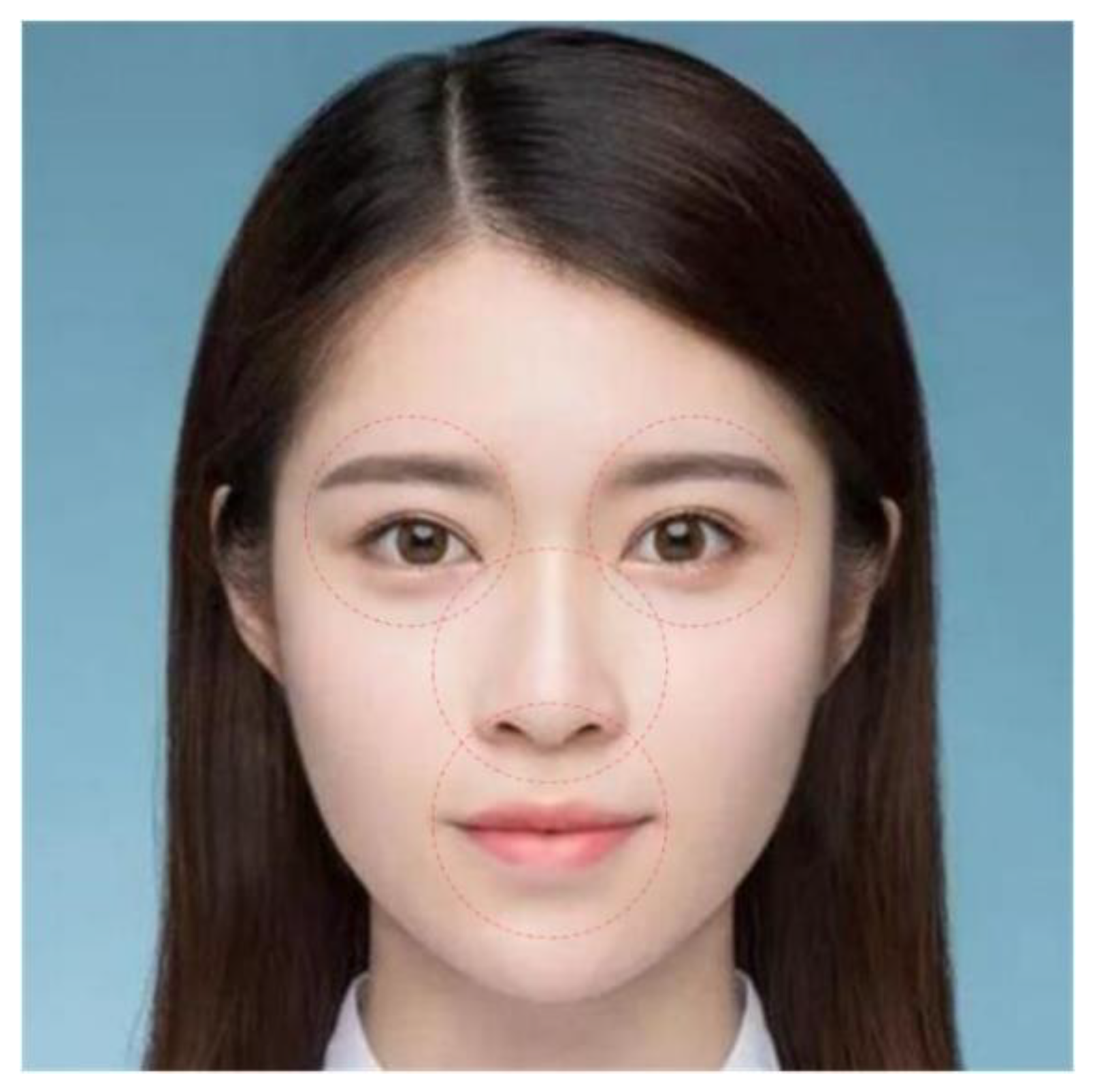
  • Firstly, the position of the facial feature information points is determined in the face image, and the face is divided into a circular domain of four characteristic parts according to the distribution of the feature points to define the feature search range.
  • Then, by introducing feature symmetry, the priority calculation is improved and the reliability of priority calculation is increased.
  • After that, the search area of the matching block is determined according to the relative position of the repair area and each feature part.
  • Finally, the HSV (Hue, Saturation, Value) color space is introduced, and the best matching block is searched according to the chroma and brightness of the sample to reduce the inpainting error and complete the face inpainting image of the facial structure features.

2. Related Work

In this section, we discuss in detail the relevant theories and methods of image inpainting, including image inpainting based on graphics and image inpainting based on deep learning. We focused on the principles and related improvements of the Criminisi algorithm to provide a prerequisite for our algorithm.

2.1. Image Inpainting Based on Graphics

In the image inpainting methods based on graphics, the PDE-based structure propagation method combines smooth prior knowledge to transfer the structural information from the outside to the inside of the target area to complete the image inpainting [12]. There are two classic methods: a method based on total variation (TV) [13] and a method based on curvature-driven diffusion (CDD) [14]. The PDE-based method targets small areas of unstructured defect areas (such as scratches) and has a good inpainting effect, but it is not suitable for large missing images that contain complex structural information [15]. The principle of the sample block-based texture synthesis image repair method constructs the repair priority from the information of the non-target region, and searches for the best matching block for the highest priority block to fill the target region to complete the image repair [16]. This type of method was originally proposed by Criminisi et al. [17] in 2003. This is used to remove the large objects in the image as the target, while the texture information of the non-target area is used to synthesize the unobstructed original background in the image.

2.2. Image Inpainting Based on Deep Learning

In the image inpainting methods based on deep learning, originally Pathak et al. [9] proposed a context encoder, which includes an encoder to capture images with missing parts and generate potential feature representations, and a decoder which uses the latent feature representations to generate missing part images, using Euclidean distance and adversarial loss function. This work is one of the earliest works of using deep neural networks for image repair. It can obtain structural features and semantic information of images, and can produce reasonable details, but the generated texture details are not fine enough, have obvious boundaries, and cannot be used for high-resolution images. Since then, many researchers improved it. Yang et al. [18] added a texture constraint while retaining the context encoder. In order to be able to process high-resolution images, they proposed a multi-scale neural patch synthesis. This method can produce more realistic and reasonable results for the structure and texture details, but the calculation cost is high, and the time taken to repair the image is long. Li et al. [19] added a global confrontation loss to the context encoder, which improved the generated image quality. Iizuka et al. [20] also improved the context encoder, adding a global discriminator and a local discriminator to ensure global consistency and local consistency, respectively. Yu et al. [21] divided the repair process into two encoding and decoding processes, one for the rough network and one for the fine network, training through global and local adversarial losses.
With the introduction of GAN, image inpainting using GAN also became a direction for researchers to explore. Yeh et al. [10] used the trained GAN model to generate an image closest to the original image without missing parts, and used the GAN loss function for the part of the training discriminator used as a prior loss to ensure the authenticity of the image. Elad et al. [22] used a pre-trained classification network to classify the repaired area and the entire image after repairing, in order to achieve the training and verification of the network. It was shown that using this type of global semantic loss function can effectively improve the details of image restoration. Altinel et al. [23] used the structural entropy of the image as a loss function to train the network, and the results showed that the method can guarantee the structural consistency of the repaired image.
RNN is a class of neural networks with short-term memory capabilities. Van den Oord et al. [11] proposed a pixel RNN model for image repair and achieved good results. However, due to the complexity of the calculation, RNN-based image repair is used in relatively few methods.

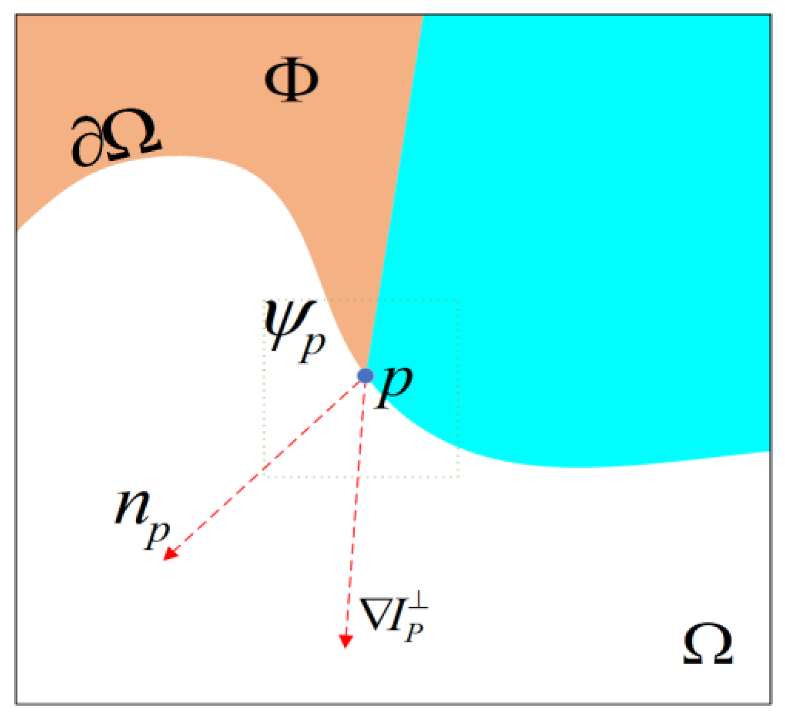
2.3. The Principle and Research of Criminisi Algorithm

Compared with the inpainting algorithm of partial differential equations with pixels as units, Criminisi algorithm inpainting uses damaged images with image blocks as units, and it can decide the size of the sample block according to needs [24]. By introducing the priority model to calculate the priority of edge pixels, the region with strong texture is repaired first to ensure the integrity of the structure, and, at the same time, the effect of later repair is enhanced effectively. The algorithm has a relatively ideal effect on images with large damaged areas.
For input image I , as shown in Figure 1, Ω is the area for inpainting, Ω is the boundary line of the area to be repaired, ψ p is the sample block to be repaired centered on point p on Ω , n p is the normal vector of point p , I p is the equal illumination line of point p (the line connected by pixel points with the same gray level), and Φ is the area where the information is completed.

2.3.1. Priority Calculation

In order to ensure the integrity of the image structure to be repaired, the damaged edges need to be repaired first, and the repair order of the pixels at the damaged edges must be determined according to the texture and confidence around the pixels, that is, the priority calculation. Suppose that the pixel with the highest priority in the damaged part is set to p , and the function for calculating the priority is defined as follows:
P ( p ) = C ( p ) D ( p ) ,
where means that two functions are multiplied. C ( p ) is the average degree of confidence of all pixels in the square area ψ p with the point p as the center. A greater degree of confidence denotes greater accuracy of the information, that is, priority is given to sample blocks containing more useful information. repair. D ( p ) is a data item, which represents the structural features in ψ p . Similarly, a larger degree of confidence denotes a stronger linear structure with higher priority, which should be repaired first.
C ( p ) = i ( ψ p Φ ) C ( i ) | ψ p | ,
D ( p ) = | I p n p | δ .
In Equation (2), | ψ p | is the area of the sample block ψ p for inpainting, and i is the damaged or repaired pixel point in ψ p . In Equation (3), δ is the normalization factor. Since the value of each pixel of a general grayscale image is represented by 8-bit or 1-byte data, the maximum grayscale value is 255; thus, δ =   255 , and I p is the direction and intensity of the iso-illumination line in the intact image near the point p , that is, the vertical vector of the boundary gradient vector. C ( p ) is initialized as follows:
C ( p ) = { 1 , p Φ 0 , p Ω .

2.3.2. Sample Block Matching

The sample block ψ p ^ to be repaired with the highest priority is found, and the best matching block ψ q of ψ p ^ in the existing region Φ is searched to repair the damaged image region. The above steps are repeated until the search for matching areas is complete. The best match criterion is defined as follows:
ψ q ^ = arg min ψ q ϕ d ( ψ p ^ , ψ q ) ,
where d ( ψ p ^ , ψ q ) is the sum of the squares of the pixel differences of the position points corresponding to the sample block ψ p ^ and the best matching block ψ q to be repaired, which is defined as
d ( ψ p ^ , ψ q ^ ) = i = 1 m j = 1 n ( p i j q i j ) 2 ,
S S D ( ψ p ^ , ψ q ) = i = 1 m j = 1 n ( p i j q i j ) 2 .
In these equations, m and n respectively represent the length and width of the sample block of the defective part of the image, and p i j and q i j in turn correspond to the known pixel values in ψ p ^ and ψ q . When the sum of squared differences (SSD) value is the smallest, the corresponding ψ q is the best matching block. As the algorithm iterates, the padding boundary needs to be updated. The specific equation is as follows:
C ( p ) = C ( p ^ ) , p ψ p ^ Ω ,
where p ^ is the pixel with the highest priority, and p is the broken pixel where the block to be repaired ψ p ^ and the area to be repaired intersect. The appeal steps are repeated until inpainting is complete. The implementation of the Criminisi algorithm is shown in the Algorithm 1.
Algorithm 1. Criminisi Algorithm.
Extract the boundary line Ω of the target area Ω
WhileΩ:
 Calculate the priority of all blocks on the boundary line Ω: P(p), ∀pΩ.
 Search for the block with the highest priority ψ p ^ .
 Search for the exemplar ψ q ^ from Φ where it minimizes d ( ψ p ^ ,   ψ q ^ ) .
 Copy image data from ψ q ^ to the missing point p on ψ p ^ ,   p ψ p ^ Ω .
 Update C(p), p ψ p ^ Ω , update the boundary line Ω.
End

2.3.3. Research Based on Criminisi Algorithm

Reference [25] modified the Criminisi algorithm and used the divergence after image gradient convolution as a data item to construct a structural tensor, which further improved the quality of the repaired image. Aiming at the problem of improper selection of padding blocks in the above method, Reference [26] proposed an image inpainting method with separation priority. The algorithm of separation priority definition was designed based on the ratio of texture information to non-texture information in the image. Experimental results showed that this method can adequately recover the texture information of the image. Reference [27] addressed the problem of sawtooth effects in the repair results and added local feature information to the priority repair model to constrain the repair order of the target blocks. By adding gradient information to reduce the search domain, the time efficiency of repair was improved. For digital face images, Reference [28] introduced the prior knowledge of faces and selected the same face image in the face database as the source area to search for matching blocks to fill the target area to complete the image restoration. In Reference [29], abundant adaptive atoms were designed from a corpus of various datasets of face images to complete image restoration using an online sparse dictionary learning algorithm to solve the problem of face images missing large areas. This method is based on the global model. The repair task is represented as an inverse problem with sparse generalization. Reference [30] proposed a face repair method based on advanced facial features, using adaptive optimization to balance them, and performing repair on the intrinsic image layer (instead of the RGB (red, green, blue) color space) to process between the target face and the guide face illumination differences, thereby further improving the final visual quality. Reference [31] proposed a method to decompose facial features into skeleton parts and texture parts and obtained sparse coefficients to repair the face image. The results showed that this method can effectively improve the image decomposition accuracy and face image inpainting. These related works provided the premise and basis for the proposal of our algorithm.

3. Method

In this section, we describe the adaptive face image inpainting algorithm based on feature symmetry in detail. Firstly, we locate the feature points of the face, and segment the face into four feature parts based on the feature point distribution to define the feature search range. Then, we construct a new mathematical model, introduce feature symmetry to improve priority calculation, and increase the reliability of priority calculation. After that, in the process of searching for matching blocks, we accurately locate similar feature blocks according to the relative position and symmetry criteria of the target block and various feature parts of the face. Finally, we introduce the HSV (Hue, Saturation, Value) color space to determine the best matching block according to the chroma and brightness of the sample, reduce the repair error, and complete the face image inpainting.

3.1. Face Local Feature Area Location

The face local feature area location includes the facial feature point location and identifying facial feature areas.

3.1.1. Facial Feature Point Location

For face image inpainting, based on explicit shape regression (ESR) [32] and facial feature point location, an adaptive window regression method model [33] is used to initially locate the facial feature points. The core of this model includes face shape initialization, adaptive adjustment window stable prediction results, and feature selection based on mutual information correlation calculation. The algorithm flow is shown in Figure 2.
Aiming at the problem of large deviation between the predicted shape and the true shape in the multi-level cascade regression of the ESR algorithm, the adaptive window regression model uses a coarse-to-fine adaptive feature selection method. This model adjusts the length of the feature window in the manner of α k = α k 1 λ μ based on the mean square error of the previous regression. The specific way is to adjust the reduction parameter λ to constrain the feature window length α by cascading regression errors. Based on the update method of the feature window, a large window is used for large error results, and a small window is used to dynamically adjust the search window for small errors, so that the prediction result continuously approaches the true value.
After the feature selection iterates N times, N candidate feature points are obtained, and the feature points are paired to make N N pixel differences. In order to avoid the disadvantages of the ESR algorithm when selecting feature points through linear correlation coefficients, the adaptive window regression method model uses a feature selection strategy based on mutual information. Firstly, the information entropy H ( μ ) of the pixel difference μ and the conditional information entropy I ( Y | μ ) of the positioning residual value Y of the feature point are calculated. Then, according to the mutual information, I ( Y | μ ) is determined between the positioning residual and the pixel difference. R , the most representative pixel difference, is selected using the entropy correlation coefficient E C C ( Y | μ ) . Finally, a regression model of random fern structure with 2 R leaf nodes is constructed based on the R pixel differences.

3.1.2. Identifying Facial Feature Areas

Based on the adaptive window regression model for facial feature point location, preliminary facial feature points are obtained. The set of facial feature points is recorded as
S = [ P 1 , , P N ] Τ , P j = ( x j , y j ) , N = 68 .
The facial feature point set is further classified into a regional feature point set: S 1 , S 2 , S 3 , S 4 , S 5 , which in turn represents the set of left eyebrow eye feature points 1–11, the right eyebrow eye feature points 12–22, nose feature points 23–31, mouth collection feature points 32–51, and the facial contour feature points 52–68. The feature points in the feature point group are distributed around the feature parts, and the range of the feature parts is determined according to the position information of the feature points. For the set S i , its center point R i ( X i , Y i ) is calculated, while X i and Y i can be obtained using the following equation:
{ X i = 1 N i j = 0 N i x i j Y i = 1 N i j = 0 N i y i j ,
where ( x i j , y i j ) S i , and N i is the number of feature points in the set S i . Using the center point R i ( X i , Y i ) as the center of the circle, the Euclidean distance from the feature point in the feature set S i to the center of the circle is calculated, and the maximum distance is selected as the maximum radius r i .
r i = m a x ( x i j , y i j ) S i ( x i j X i ) 2 + ( y i j Y i ) 2 ,
where i = 1 , 2 , 3 , 4 . The circular area of the maximum radius of the feature part is obtained by using R i as the center and r i as the maximum radius to obtain the feature part area E i of the face image. The experimental results are shown in Figure 3.

3.2. Calculation of Priority Function Based on Feature Symmetry

The setting of the priority greatly affects the quality and effect of image inpainting. The priority function P ( p ) is defined as the product of the confidence item C ( p ) and the data item D ( p ) . However, in the actual repair process, the confidence value drops sharply and quickly approached zero, which makes the change trend of the priority in accordance with the change trend of the confidence C ( p ) , resulting in unreliable calculation of the priority and deviations, which affects the final repair effect. In order to ensure the continuity of the structural information of the restored image, according to the principle of local feature symmetry of the face image [34], this paper considers the surrounding information of the block to be repaired, introduces the symmetry between the block to be repaired and the neighborhood block, and uses it as the priority calculation. In part, if the neighborhood block shows similar information, then it is an extension of similar features. Therefore, the improved priority calculation formula is shown below.
P ( p ) = α C ( P ) + β D ( p ) + γ E ( p ) ,
where α , β , λ is the weighting factor, 0 α , β , γ 1 and α + β + γ = 1 , and the initial value is set to α = 0.3 , β = 0.4 , γ = 0.3 . E ( p ) is the symmetry between the block to be repaired and its neighboring block, which is defined as follows:
E ( p ) = A r e a ( N ϕ ( p ) ) A r e a ( N ( p ) ) × q N ϕ ( p ) exp ( d ( ψ p ^ , ψ q ) P D ( p , q ) ) ,
where N ( p ) is the domain block, the center point is q , N ϕ ( p ) is the intersection area of N ( p ) and the entire partial area, A r e a ( N ϕ ( p ) ) A r e a ( N ( p ) ) is the ratio of the known part and domain area in the domain, exp ( d ( ψ p ^ , ψ q ) P D ( p , q ) ) is used to calculate the similarity between the two modules, d ( ψ p ^ , ψ q ) is the sum of the squares of the pixel differences at the corresponding points between the sample block and the matching block, and P D ( p , q ) is a penalty function, which is used to reward close-range pixels and punish long-range pixels. According to human visual habits, the adjacent domain is addressed before the more distant areas. The information of the adjacent domain is usually more important. Its calculation formula is shown below.
P D ( q , p ) = ( x p x q ) 2 + ( y p y q ) 2 ,
where x p and x q represent the abscissa of p and q pixels, whereas y p and y q are the ordinate of p and q pixels. By improving the priority formula, the phase field information is fully considered in the repair process, the repair process is more reasonable, and the priority repair order is more reliable.

3.3. Adaptive Selection Method of Sample Block Size

For sample block inpainting methods, most use fixed-size sample blocks for inpainting. Even when using the same method, different sample block sizes can lead to completely different visual effects. For regions with simple textures, the information changes between the target block and the surrounding neighborhoods are relatively smooth and similar. Selecting larger sample blocks can greatly reduce the time consumption of the algorithm and speed up the repair process. However, in a texture-rich area, if a larger sample segment is selected, the texture information is more in one sample, which can easily cause inconsistencies in the edge transitions between blocks and block effects. Therefore, it is necessary to change the sample size to meet the needs of different regions.
This method uses an adaptive function to initialize the sample size before the repair process. Firstly, w 0 is used as the standard sample size to calculate the complexity of the sample itself, with dimensions of 9 × 9. The concept of sample sparsity S ( p ) is then used to represent complexity. It is defined as follows:
S ( p ) = [ q N s ( p ) ω p ^ , q 2 ] C ( p ) ,
where N S ( p ) is the pixels in the intact area and the sample block ψ p , and ω p ^ , q is the similarity between the sample block ψ p ^ of the image to be repaired and the matching block ψ q to be matched, which is defined as follows:
ω p ^ , q = 1 Z ( p ) exp ( d ( ψ p ^ , ψ q ) 25 ) ,
where Z ( p ) is a normalization constant used to satisfy q N s ( p ) ω p ^ , q 2 = 1 . This paper uses the sum of squared differences (SSD) to calculate the difference between ψ p ^ and ψ q . When the value of S ( p ) is large, it means that ψ p ^ does not have symmetry with the surrounding samples; thus, ψ p ^ is placed in the edge region. Conversely, the small value of S ( p ) means that ψ p ^ has a high similarity with the surrounding samples, and ψ p ^ is placed in a stable region at this time.
In the algorithm of this paper, W m is defined as the size of the matching block selected during the matching process, and W p is defined as the size of the sample block selected during the repair process. Therefore, if the proposed method is repaired in the edge area, for inconsistencies, this article uses large matching blocks in the matching process to obtain more information, and it uses small sample blocks in the repair process to reduce other repairs. If the proposed method repairs the samples in a stable area, a larger repair sample is selected to increase the speed of the repair process.
W m = { 1.5 ω 0 ,   S ( p ) λ 1 ( P max P min ) + P min ω 0 ,   λ 2 ( P max P min ) + P min S ( p ) λ 1 ( P max P min ) + P min 1.25 ω 0 ,   S ( p ) λ 2 ( P max P min ) + P min   ,
W p = { 0.75 ω 0 ,   S ( p ) λ 1 ( P max P min ) + P min ω 0 ,   λ 2 ( P max P min ) + P min S ( p ) λ 1 ( P max P min ) + P min 1.25 ω 0 ,   S ( p ) λ 2 ( P max P min ) + P min   ,
where p max and P min are the maximum and minimum values of S ( p ) , respectively. Thresholds λ 1 and λ 2 are obtained experimentally, and they were set to 0.55 and 0.15 in the experiments in this paper.

3.4. Sample Matching Method Based on HSV Color Space

In order to make up for the limitation whereby matching the sample blocks only from the sum of squares of gray differences is only suitable for the repair of gray images, the algorithm in this paper considers adding relevant parameters in the HSV color space when comparing the sample blocks to compare the sample blocks. The HSV model is derived from the RGB cube model and can be converted from the RGB color space to the HSV color space. The conversion formula mentioned in Reference [24] is adopted. In the HSV model, the hue H of the image is the main judgment of the color, and the brightness V has a greater impact on the visual continuity of the image. Therefore, adding the difference between the hue H and the brightness V when matching the sample blocks can increase the accuracy of the matching. HSD (sum of squared differences of hue) between the image block ψ p to be repaired and the sample block ψ q to be matched is defined as follows:
H S D ( ψ p , ψ q ) = i = 1 m j = 1 n ( S p i j S q i j ) 2 ,
where S p i j and S q i j respectively represent the hue in the HSV model of the image block to be repaired and the matched image block at the central pixel point ( i , j ) . In the same way, VSD (sum of squared differences of value) between the image block ψ p to be repaired and the sample block ψ q to be matched is defined as follows:
V S D ( ψ p , ψ q ) = i = 1 m j = 1 n ( V p i j V q i j ) 2 .
Before comparing hue and brightness, the corresponding formula needs to be used to convert the picture to the HSV color space; then, the sample blocks are searched and matched in the intact area, and the similarity is determined by calculating the square sum of the difference between the corresponding pixel parameters, such that the color parameters are poor. The values are defined as follows:
S S D a l l ( ψ p , ψ q ) = S S D 255 + σ 1 H S D + σ 2 V S D ,
where σ 1 and σ 2 are proportional parameter values, which can be changed according to the actual effect, and they are taken as σ 1 = 0.5 and σ 2 = 0.5 in advance. Finally, we can get the improved matching principle, shown below.
ψ q = arg min [ S S D a l l ( ψ p , ψ q ) ] .

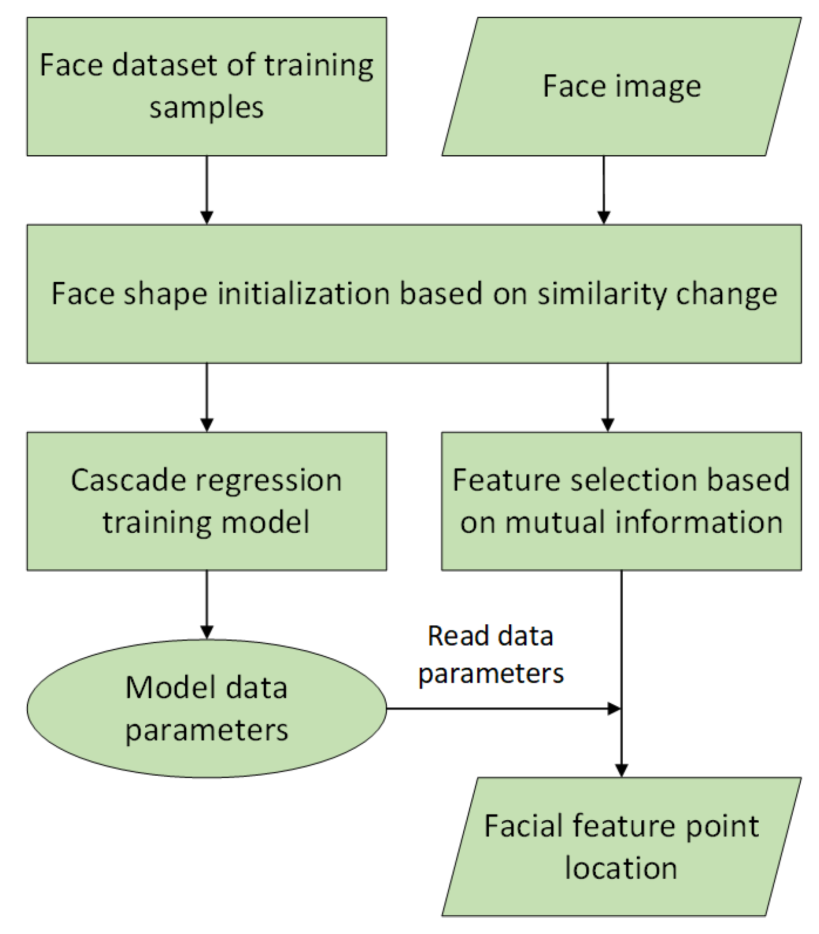
3.5. Algorithm Implementation
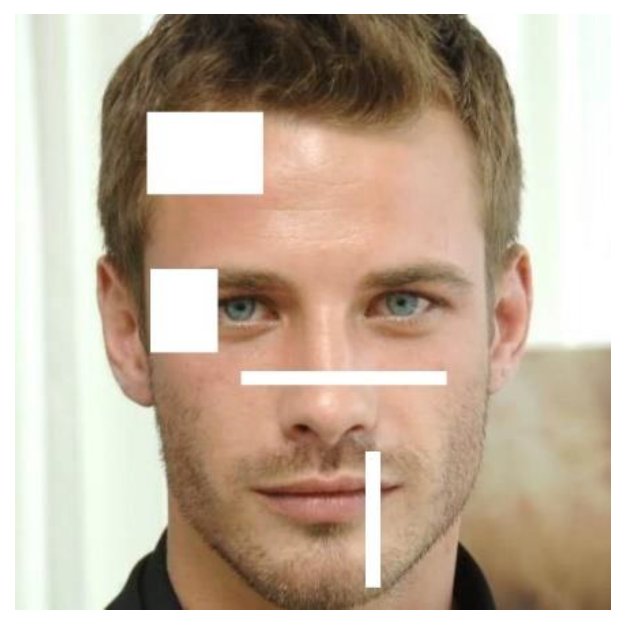
The implementation process of the algorithm proposed in this paper is as follows:
  • The face image I and the inpainting area Ω are input in the image.
  • The feature point set is determined by the adaptive window regression model of facial feature point location, and the feature point set is classified as S : S 1 , S 2 , S 3 , S 4 , S 5 , representing the left eyebrow feature area, right eyebrow feature area, nose feature area, mouth feature area, and face contour region, respectively.
  • The center R i ( X i , Y i ) of each set S 1 , S 2 , S 3 , S 4 is calculated. The Euclidean distance between the points in S i and R i is calculated, and the maximum radius r i of the circular domain is determined using Equation (8), where N i represents the number of feature points in S i . Taking R i as the center of the circle and r i as the maximum radius, a circle E i with a maximum radius of the characteristic part is obtained.
  • The confidence of all pixels in the image Ω to be repaired is initialized according to Equation (4).
  • The highest-priority weight is obtained by Equation (9) and filled in the boundary of the area to be repaired.
  • The sizes of the sample block and the matching block are adaptively selected according to Equations (15)–(18).
  • According to the matching principle of Equation (22), multiple parameters are used to find the sample block with the highest symmetry.
  • The boundary information of the repaired area is updated, and the confidence of the pixel values of the image is updated. The confidence of the pixels in the repaired area is mainly updated, and then the next pixel is prepared for inpainting. Steps (2–8) are repeated until the face image is repaired.
  • The face image is output after inpainting is accomplished.

4. Experiments and Results

In this section, we introduce the methods and results in our experiments. For the experimental results, we try to compare and analyze the overall structural information and local texture features of the inpainting face image.

4.1. Experimental Method and Environment
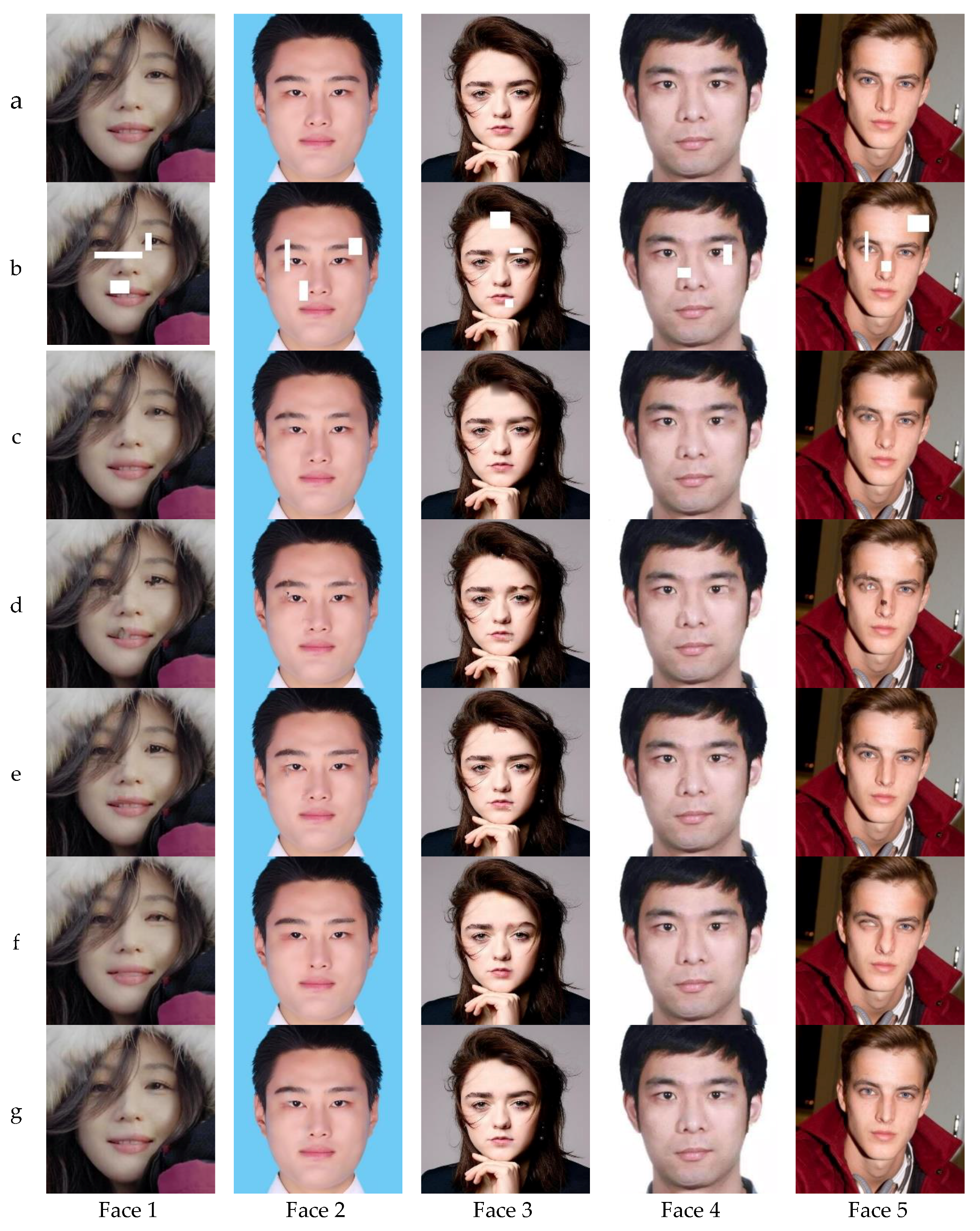
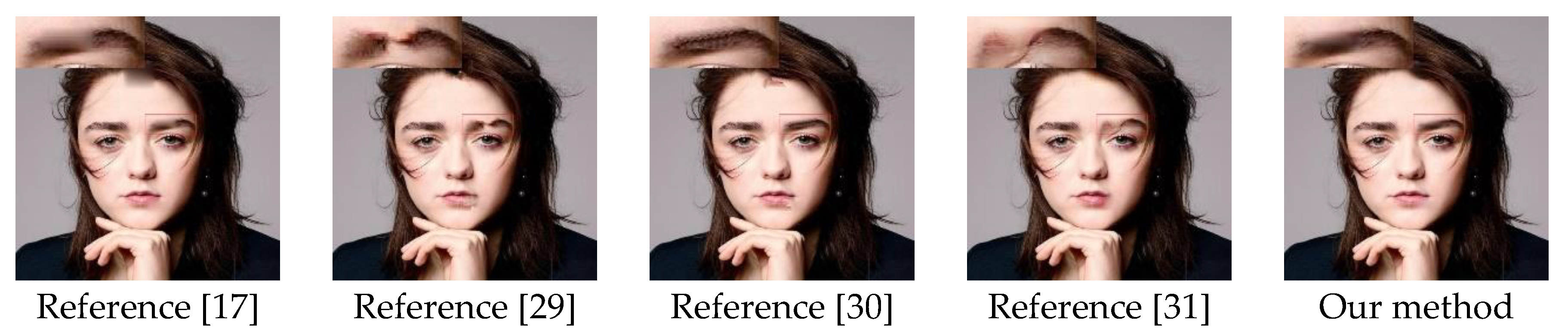
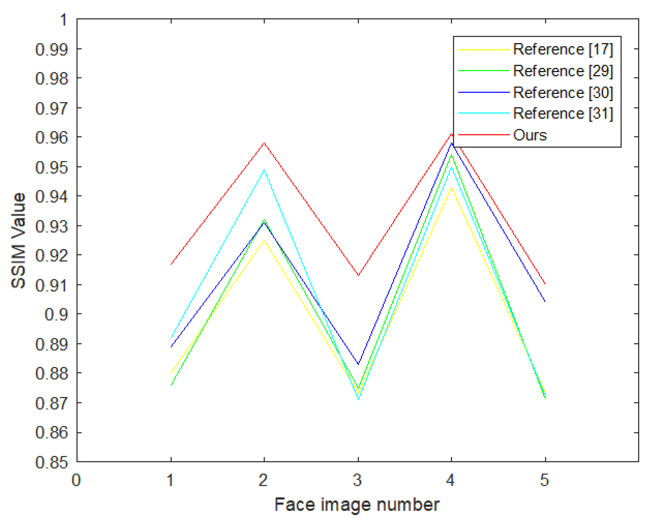
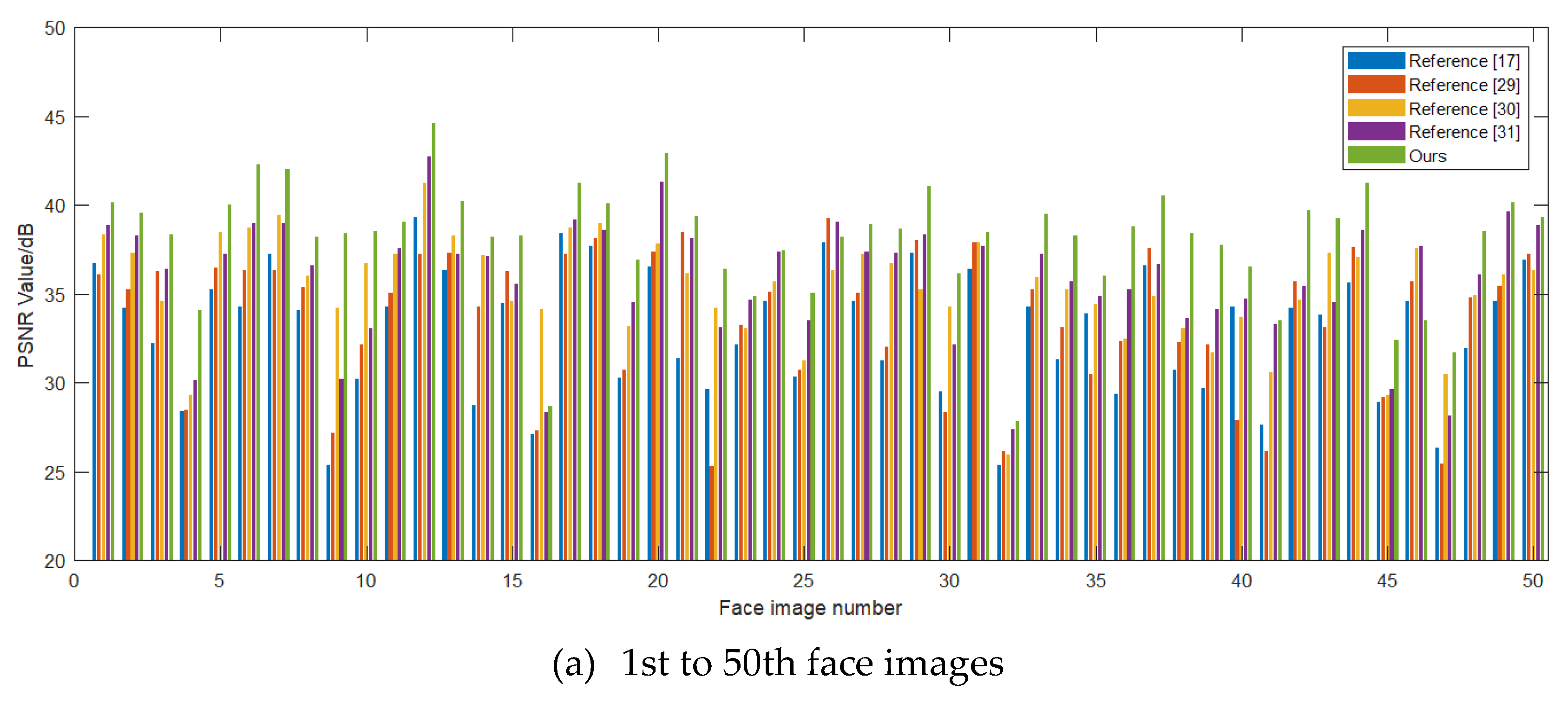
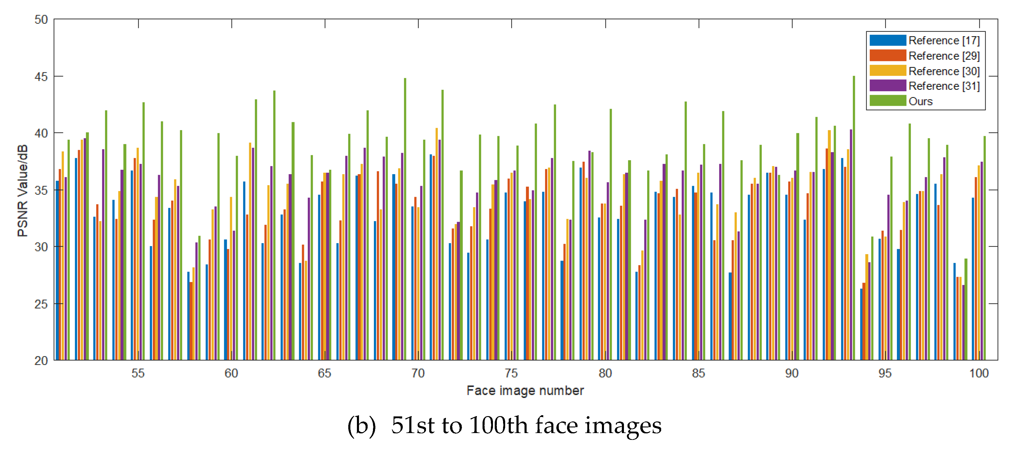
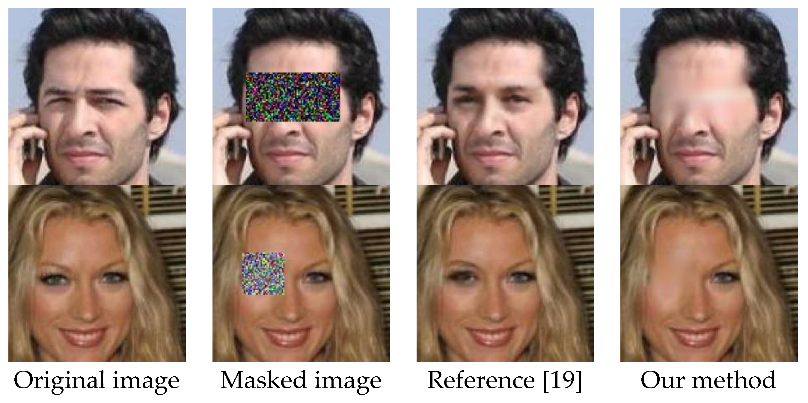
The algorithm proposed in this paper and the comparative face image restoration algorithm experiments were implemented in MATLAB simulation software. The experimental environment configuration is shown in Table 1.
The experimental image was a 512 × 512 face image extracted from the original photo, and a mask was artificially added to the facial feature part of the experimental image to simulate a damaged face image. The effect is shown in Figure 4.

4.2. Result

The experimental results were used to compare our algorithm with the methods proposed in References [17,29,30,31], and the repair effect of some damaged face images is shown in Figure 5. From the perspective of visual effects, the effectiveness of our algorithm in reducing the structural connectivity and global consistency of feature parts of the inpainting face image was better than the methods in References [17,29,30,31]. Among them, References [30,31] consider the distribution characteristics of the image structure, and the inpainting results were better than those of References [17,29]. The experimental results of inpainting the characteristic parts of faces 1 and 5 in Figure 6 show that References [17,29] failed when inpainting the structural features, and there were even cases where other characteristic parts were copied to the target block, and the inpainting results had obvious structural inconsistencies.
In order to observe and compare the detailed features of the face after inpainting, the results of the repaired eyebrows of face 3 were enlarged, as shown in Figure 6. In the process of inpainting eyebrows, the method in References [17,30] filled the target area with the hair part as a matching block. References [29,31] failed to completely repair the shape of the feature part. However, the adaptive priority model proposed by this paper took into account the symmetry information of the local facial features and repaired the eyebrow shape. At the same time, the search domain for matching blocks was limited, and the matching block found was the eyebrow part. Therefore, the inpainting effect was better than the contrast algorithm in the experiment.

5. Discussion

In this section, we discuss the experimental results using objective evaluation methods. In addition, we try to discuss and compare the GAN face image inpainting methods based on deep learning.

5.1. Discussion on the Validity of Our Algorithm

In order to objectively discuss and analyze the face image inpainting effect of our algorithm, we used the peak signal-to-noise ratio (PSNR) and structural similarity (SSIM) to compare and evaluate the effectiveness of our algorithm [35,36,37]. The evaluation indicators are defined as follows:
P S N R = 10 l g ( 255 2 M S E ) ,
M S E = 1 W × H x = 1 W y = 1 H [ I ( x , y ) I ^ ( x , y ) ] ,
S S I M = [ l ( I , I ^ ) c ( I , I ^ ) s ( I , I ^ ) ] .
In Equation (24), MSE is the mean square error of the contrast image, W × H is the image size, I and I ^ are the original image and the restored image, and l ( x ) , c ( x ) , s ( x ) are the brightness, contrast, and structure comparison function, respectively. A larger PSNR value denotes a higher similarity of the two images. S S I M ( 0 , 1 ) ; as its value approaches 1, structural features of the two pictures become closer.
For the face inpainting results in Figure 5, the PSNR and SSIM of each algorithm were statistically tested, as shown in Table 2 and Figure 7. Through comparison, it can be found that the PSNR value of the inpainting results of our method performed best in five images, with values 0.591–5.898 dB higher than the comparison methods. In terms of structural similarity, the SSIM value of the algorithm in this paper could reach a maximum of 0.961. Discussion and analysis using objective review indicators scientifically proved that the algorithm proposed in this paper has certain advantages in face image inpainting.
In addition, in the experiment, we calculated the PSNR values of each algorithm when repairing 100 damaged face images, and the experimental results of 100 face images are shown in Figure 8. For the PSNR value when 100 face inpainting images, there were only five face images with performance lower than the comparison methods. The average PSNR values of References [17,29,30,31] in the comparison experiment were 32.916 dB, 33.631 dB, 35.074 dB, and 35.811 dB, and the average PSNR value of our algorithm was 38.692 dB. Compared with the comparison algorithm, the PSNR was improved by 2.881–5.776 dB, which further demonstrates the effectiveness of the algorithm in this paper.

5.2. Discussion on the Efficiency of Our Algorithm

Compared with the reference methods using a global search scheme, our method searches in a large circular area of feature parts when searching for matching blocks; thus, it has an absolute advantage in terms of time consumption. In order to objectively verify the time superiority of our method, the time consumption of each experiment in Figure 5 is shown in Table 3. As can be seen from the table, the time consumption of the repair method was closely related to the image size and the number of broken pixels. Reference [31] consumed the most time, because this method needs to decompose the face image into the skeleton part and the texture part to obtain the sparse coefficient to repair the face image, which increases the time consumption of the algorithm. The method of Reference [30] uses the adaptive optimization method to estimate the balance of the repaired area; thus, the experiment time is relatively better than the methods of References [17,29,31]. Our method firstly locates the feature area of the face, then reduces the search range of the local matching block, and adaptively repairs the damaged area of the face image based on the symmetry of the local feature of the face, which results in accurate inpainting of the target domain, as well as a shortened inpainting time.
In 100 face image inpainting comparison experiments, we used the time required for inpainting a unit pixel to represent the concept of inpainting efficiency. The calculation method is shown in Equation (26), where i is the face image, T i is the time taken for inpainting the face image, and P i x e l i is the pixel value in the face image that needs inpainting, with units of ms/dpi. The experimental results are shown in Table 4; our algorithm improved the results by 35%, 22%, 12%, and 49%, respectively, compared to References [10,16,17,18], thereby explaining to a certain extent that our algorithm has certain advantages in face image inpainting efficiency.
Inpainting   efficiency = 1 100 i = 1 100 T i P i x e l i .

5.3. Discussion on the Comparison with GAN

When a face image contains large defect areas, especially when the local feature information of the face is completely lost, the face image inpainting algorithm based on graphics struggles to achieve a good inpainting effect. With the development of machine learning, especially the emergence of the generative adversary network (GAN), a face image inpainting algorithm based on deep learning can effectively solve the above problems. We carried out an experimental comparison between our method and the GAN method (Reference [19]) for face image repair with large areas of missing features, the face image inpainting results are shown in Figure 9. Because our algorithm improves the face image inpainting algorithm based on graphics and introduces feature symmetry, when inpainting a face image with missing local feature information, it was impossible to correctly obtain similar feature matching blocks to fill in the missing region, and the surrounding skin features were incorrectly selected to fill the missing region of the face image. Therefore, it is shown that the improved method based on feature symmetry in this paper still cannot overcome the shortcomings of face inpainting algorithms based on graphics that cannot obtain high-level structural features and semantic information of large areas of missing feature information during face image inpainting. The face image inpainting method based on deep learning uses a trained GAN model to generate an image closest to the non-missing part of the original image, and uses part of the GAN loss function to train the discriminator as the prior loss. Visually, it guarantees the authenticity of the face image. However, whether the missing features of the face image generated by GAN are consistent with the original features and can be gradually applied to fields such as face recognition is an academic issue worthy of discussion.

6. Conclusions

Because the traditional image restoration algorithm has certain flaws in the calculation of the priority value, when performing face image inpainting for facial images with weak texture structure features, the methods based on sample block texture synthesis to restore face images often have structural disconnection and irrational filling, which greatly affects the visual effect of the face image. Therefore, this paper proposed an adaptive face image inpainting algorithm based on feature symmetry. Firstly, we locate the feature points of the face, and then segment the face into four feature parts based on the feature point distribution to define the feature search range. Then, we construct a new mathematical model, introduce feature symmetry to improve priority calculation, and increase the reliability of priority calculation. After that, in the process of searching for matching blocks, we accurately locate similar feature blocks according to the relative position and symmetry criteria of the target block and various feature parts of the face. Finally, we introduce the HSV color space to determine the best matching block according to the chroma and brightness of the sample, reduce the repair error, and complete the face image inpainting.
In order to objectively evaluate the inpainting effect of our algorithm, we compared it with the methods of References [17,29,30,31], and used peak signal-to-noise ratio (PSNR) and structure similarity (SSIM) to compare and evaluate the effectiveness of these algorithms. The experimental results show that the face image inpainting using our algorithm retained the face structure, and the visual observation was close to the real face features. From the experimental data, for the five face repair images in this paper, the values of PSNR and SSIM of our algorithm were optimal. After inpainting 100 face images, the average PSNR of our method improved by 2.881–5.776 dB compared to the comparison methods. It was proven by experiments that the algorithm in this paper had the shortest time to repair the same damaged face image. When inpainting a damaged pixel area of the same size in a face image, our algorithm took less time than the comparison algorithms. After comprehensive discussion and objective analysis, were proved the effectiveness and superiority of the adaptive face image inpainting algorithm based on feature symmetry proposed in this paper.
In addition, in the comparison with face image inpainting based on deep learning, we found that the improved algorithm in this paper struggled to overcome the shortcomings of the face inpainting based on graphics. Therefore, in future work, we intend to introduce the principle of feature symmetry to deep learning methods, and build a generative adversarial network based on feature symmetry for face image inpainting, so as to retain as much face feature information as possible to meet the needs of face recognition when inpainting large areas of face damage images.

Author Contributions

Supervision, H.L.; methodology, Z.N. and H.L.; software Z.N. and Y.M.; writing—original draft preparation, Y.L.; writing—review and editing, Z.N.; funding acquisition, J.Y. All authors read and agreed to the published version of the manuscript.

Funding

This research was funded by the Science and Technology Support Plan Fund of Guizhou Province, grant number (2019) 2152.

Acknowledgments

The authors acknowledge the financial support from the Science and Technology Support Plan Fund of Guizhou Province, and the laboratory equipment support from the College of Electrical Engineering of Guizhou University.

Conflicts of Interest

The authors declare no conflicts of interest.

References

  1. Yang, W.K.; Zhang, X.; Li, J. A local multiple patterns feature descriptor for face recognition. Neurocomputing 2020, 373, 109–122. [Google Scholar] [CrossRef]
  2. Ma, L.; Deng, Z. Real-time facial expression transformation for monocular RGB video. Comput. Graph. Forum. 2019, 38, 470–481. [Google Scholar] [CrossRef] [Green Version]
  3. Li, H.; Yu, J.H.; Ye, Y.T.; Bregler, C. Realtime facial animation with on-the-fly correctives. ACM Trans. Graph. 2013, 4, 42. [Google Scholar] [CrossRef]
  4. Mousas, C.; Anagnostopoulos, C.N. Structure-aware transfer of facial blendshapes. In Proceedings of the 31st Spring Conference on Computer Graphics, Smolenice, Slovakia, 22–24 April 2015; pp. 55–62. [Google Scholar]
  5. Zhang, D.; Tang, X.H. Image inpainting based on combination of wavelet transform and texture synthesis. J. Image Graph. 2015, 20, 882–894. [Google Scholar]
  6. Guo, Q.; Gao, S.; Zhang, X. Patch-based image inpainting via two-stage low rank approximation. IEEE Trans. Vis. Comput. Graph. 2017, 24, 2023–2036. [Google Scholar] [CrossRef] [PubMed]
  7. Hoeltgen, L.; Mainberger, M.; Hoffmann, S. Optimising spatial and tonal data for PDE-based inpainting. Mathematics 2017, 18, 35–83. [Google Scholar]
  8. Kumar, V.; Mukherjee, J.; Mandal, S.K.D. Image Inpainting Through Metric Labeling via Guided Patch Mixing. IEEE Trans. Image Process. 2016, 25, 5212–5226. [Google Scholar] [CrossRef]
  9. Pathak, D.; Krahenbuhl, P.; Donahue, J. Context encoders: Feature learning by inpainting. In Proceedings of the IEEE Conference on Computer Vision and Pattern Recognition, Las Vegas, NV, USA, 26 June–1 July 2016; pp. 2536–2544. [Google Scholar]
  10. Yeh, R.A.; Chen, C.; Lim, T.Y. Semantic image inpainting with deep generative models. In Proceedings of the IEEE Conference on Computer Vision and Pattern Recognition, Honolulu, HI, USA, 21–26 July 2017; pp. 6882–6890. [Google Scholar]
  11. Van de oord, A.; Kalchbrenner, N.; Kavukcuoglu, K. Pixel recurrent neural networks. In Proceedings of the 33rd International Conference on Machine Learning, New York, NY, USA, 19–24 June 2016; pp. 2611–2620. [Google Scholar]
  12. Hasegawa, M.; Kako, T.; Hirobayashi, S. Image inpainting on the basis of spectral structure from 2-D nonharmonic analysis. IEEE Trans. Image Process. 2013, 22, 3008–3017. [Google Scholar] [CrossRef]
  13. Wu, X.L. Color demosaicking by local directional interpolation and nonlocal adaptive thresholding. J. Electron. Imaging 2011, 20, 023016. [Google Scholar] [CrossRef] [Green Version]
  14. Chan, T.F.; Shen, J. Variational image inpainting. Commun. Pure Appl. Math. 2010, 58, 579–619. [Google Scholar] [CrossRef] [Green Version]
  15. Memg, H.Y.; Zhai, D.H.; Li, M.X. Image inpainting algorithm based on pruning samples referring to four-neighborhood. J. Comput. Appl. 2018, 38, 1111–1116. [Google Scholar]
  16. Wang, J.; Lu, K.; Pan, D. Robust object removal with an exemplar-based image inpainting approach. Neurocomputing 2014, 123, 150–155. [Google Scholar] [CrossRef]
  17. Criminisi, A.; Patrick, P.; Toyanma, K. Object Removal by Exemplar-Based Inpainting. In Proceedings of the 2003 IEEE Computer Society Conference on Computer Vision and Pattern Recognition, Madison, WI, USA, 18–20 June 2003; pp. 721–728. [Google Scholar]
  18. Yang, C.; Lu, X.; Lin, Z. High-resolution image inpainting using multi-scale neural patch synthesis. In Proceedings of the IEEE Conference on Computer Vision and Pattern Recognition, Honolulu, HI, USA, 21–26 July 2017; pp. 4076–4084. [Google Scholar]
  19. Li, Y.J.; Liu, S.F.; Yang, J.M. Generative face completion. In Proceedings of the IEEE Conference on Computer Vision and Pattern Recognition, Honolulu, HI, USA, 21–26 July 2017; pp. 5892–5900. [Google Scholar]
  20. Iizuka, S.; Simo-Serra, E.; Ishikawa, H. Globally and locally consistent image completion. ACM Trans. Graph. 2017, 36, 107. [Google Scholar] [CrossRef]
  21. Yu, J.H.; Lin, Z.; Yang, J.M. Generative image inpainting with contextual attention. In Proceedings of the IEEE Conference on Computer Vision and Pattern Recognition, Salt Lake City, UT, USA, 18–22 June 2018; pp. 5505–5514. [Google Scholar]
  22. Image Inpainting Using Pre-Trained Classification CNN. Available online: https://www.researchgate.net/publication/325471259_Image_Inpainting_Using_Pre-Trained_Classification_CNN (accessed on 31 May 2018).
  23. Altinel, F.; Ozay, M.; Okatani, T. Deep structured energy-based image inpainting. In Proceedings of the 24th International Conference on Pattern Recognition, Beijing, China, 20–24 August 2018; pp. 423–428. [Google Scholar]
  24. Siadat, S.Z.; Yaghmaee, F.; Mahdav, P. A new exemplar-based image inpainting algorithm using image structure tensors. In Proceedings of the 24th Iranian Conference on Electrical Engineering, Shiraz, Iran, 10–12 May 2016; pp. 995–1001. [Google Scholar]
  25. Kui, L.; Jie, Q.T.; Ben, Y.S. Exemplar-based image inpainting using structure tesnor. In Proceedings of the International Conference on Advanced Computer Science and Electronics Information, Beijing, China, 25–26 July 2013; pp. 18–24. [Google Scholar]
  26. Liang, J.D.; Ting, Z.H.; Xi, L.Z. Exemplar-Based Image Inpainting Using a Modified Priority Definition. PLoS ONE 2015, 10, e0141199. [Google Scholar]
  27. Liu, H.B.; Ye, X.H.; Wang, Z.F. Arc promoting image inpainting using exemplar searching and priority filling. J. Image Grapgics 2018, 21, 993–1003. [Google Scholar]
  28. Yue, T.Z.; Yu, S.W.; Timonthy, S. Patch-guided facial image inpainting by shape propagation. J. Zhejiang Univ. Sci. A 2009, 10, 232–238. [Google Scholar]
  29. Sulam, J.; Elad, M. Large inpainting of face images with trainlets. IEEE Signal Process. Lett. 2016, 23, 1839–1843. [Google Scholar] [CrossRef]
  30. Jampour, M.; Li, C.; Yu, L.F.; Zhou, K.; Lin, S.; Bischof, H. Face inpainting based on high-level facial attributes. Comput. Vis. Image Underst. 2017, 161, 29–41. [Google Scholar] [CrossRef]
  31. Wang, L.; Zhang, Y. Weak Texture Face Image Local Damage Point Repair Method. Comput. Simul. 2018, 35, 429–432. [Google Scholar]
  32. Cao, X.; Wei, Y.; Wen, F. Face Alignment by Explicit Shape Regression. Int. J. Comput. Vis. 2014, 107, 177–190. [Google Scholar] [CrossRef]
  33. Wei, J.W.; Wang, X.; Yuan, Y.B. Adaptive window regression method for face alignment. J. Comput. Appl. 2019, 39, 1459–1465. [Google Scholar]
  34. Su, Y.; Liu, Z.; Ban, X. Symmetric Face Normalization. Symmetry 2019, 11, 96. [Google Scholar] [CrossRef] [Green Version]
  35. Prateek, G.; Priyanka, S.; Satyam, B.; Vikrant, B. A modified PSNR metric based on HVS for quality assessment of color images. In Proceedings of the International Conference on Communication and Industrial Application, Kolkata, West Bengal, 26–28 December 2011; pp. 1–4. [Google Scholar]
  36. Wang, Z.; Bovik, A.C.; Sheikh, H.R.; Simoncelli, E.P. Image quality assessment: From error visibility to structural similarity. IEEE Trans. Image Process. 2004, 13, 600–612. [Google Scholar] [CrossRef] [PubMed] [Green Version]
  37. Alain, H.; Djemel, Z. Image Quality Metrics: PSNR vs. SSIM. In Proceedings of the 20th International Conference on Pattern Recognition, Istanbul, Turkey, 23–26 August 2010; pp. 2366–2369. [Google Scholar]
Figure 1. Schematic diagram of texture synthesis algorithm based on sample block.
Symmetry 12 00190 g001
Figure 2. Flow chart of facial feature point location model.
Symmetry 12 00190 g002
Figure 3. Effects of facial area feature positioning.
Symmetry 12 00190 g003
Figure 4. Simulated human face image damage.
Symmetry 12 00190 g004
Figure 5. Results of different algorithms for face inpainting (in this figure, a describes the original face image; b describes the simulated face damage image; cf describe the results of face image inpainting of References [17,29,30,31], respectively, and g describes the results of our algorithm in this paper).
Symmetry 12 00190 g005
Figure 6. Comparison results of facial feature restoration details.
Symmetry 12 00190 g006
Figure 7. Comparison of structural similarity (SSIM) values.
Symmetry 12 00190 g007
Figure 8. The result of peak signal-to-noise ratio (PSNR) values when inpainting 100 face images.
Symmetry 12 00190 g008aSymmetry 12 00190 g008b
Figure 9. Comparison results of our method and Reference [19] (these face images were taken from Reference [19]).
Symmetry 12 00190 g009
Table 1. Experimental environment configuration.
ItemsModelParameter
Operating systemWindows 10Professional 64-bit
Programming toolMATLABR2017b 64-bit
CPU(central processing unit)Intel (R) Core (TM)I7-9700K 3.6 GHz
RAM(Random Access Memory)HyperX PredatorDDR4 16 G
GPU(Graphics Processing Unit)NVIDIA GeForceRTX 1080 Ti, 1480 MHz, 11 GB
Table 2. Peak signal-to-noise ratio (PSNR) value comparison data (unit: dB).
AlgorithmsFace 1Face 2Face 3Face 4Face 5
Reference [17]33.02735.76133.94635.74231.412
Reference [29]32.42635.80433.24135.86729.884
Reference [30]35.18836.67235.61437.24034.291
Reference [31]36.05238.52433.35438.06132.177
Our method38.32439.06036.84239.55235.017
Table 3. Time consumption comparative data of face image inpainting.
ImagesInpainting Pixels (dpi)Reference [17] (s)Reference [29] (s)Reference [30] (s)Reference [31] (s)Our Method (s)
Face 1650082.5471.5965.82108.0556.83
Face 2392547.8042.2339.1674.3834.31
Face 3422554.9747.7841.3878.1835.07
Face 4270035.2727.8126.8152.1322.37
Face 5455059.0451.4245.2781.9236.86
Table 4. The comparison results of inpainting efficiency in 100 face images.
MethodReference [17]Reference [29]Reference [30]Reference [31]Our Method
Inpainting efficiency13.04 ms/dpi10.92 ms/dpi9.71 ms/dpi16.69 ms/dpi8.47 ms/dpi

