Article

Periodic, Quasi-Periodic, and Chaotic Motions to Diagnose a Crack on a Horizontally Supported Nonlinear Rotor System

by
Nasser A. Saeed
1,*,
Mohamed S. Mohamed
2,3 and
Sayed K. Elagan
2,4
1
Department of Physics and Engineering Mathematics, Faculty of Electronic Engineering, Menoufia University, Menouf 32952, Egypt
2
Department of Mathematics and Statistics, College of Science, Taif University, P.O. Box 11099, Taif 21944, Saudi Arabia
3
Mathematics Department, Science Faculty, University Al-Azher, Nasr City 11884, Egypt
4
Department of Mathematics, Faculty of Science, Menoufia University, Shebin Elkom 32511, Egypt
*
Author to whom correspondence should be addressed.
Symmetry 2020, 12(12), 2059; https://doi.org/10.3390/sym12122059
Submission received: 18 November 2020 / Revised: 8 December 2020 / Accepted: 9 December 2020 / Published: 11 December 2020
(This article belongs to the Section Mathematics)

Abstract

:
This work aims to diagnose the crack size of a nonlinear rotating shaft system based on the qualitative change of the system oscillatory characteristics. The considered system is modeled as a two-degree-of-freedom horizontally supported nonlinear Jeffcott rotor system. The influence of the crack size on the system whirling motion for the primary, superharmonic, and subharmonic resonance cases are investigated utilizing the bifurcation diagram, Poincaré map, frequency spectrum, and whirling orbit. The obtained numerical results revealed that the cracked system whirling motion is subjected to a continuous qualitative change as the crack size increases for the superharmonic resonance case, where the system can exhibit period-1, period-2, quasi-periodic, period-3, period-doubling, chaotic, and period-2 motions, sequentially. In addition, an asymmetry is observed in the system whirling orbit due to both the shaft weight and shaft crack. Moreover, it is found that the disk eccentricity does not affect the nature of these motions. Accordingly, we illustrated a simple method to diagnose the existence of such a crack and to quantify its size via monitoring the system lateral vibrations at the superharmonic resonance. Finally, all the obtained numerical results are concluded and a comparison with already published work is included.

1. Introduction

Rotating machines cover a wide range of engineering applications that provide the backbone of numerous industries such as steam turbines, generators, gas turbines, aerospace, pumps, turbomachinery, automobile engines, high-speed compressors etc. Such machines need to run safely under different operational conditions to ensure their continued productivity and to prevent any catastrophic failure. Nonlinear vibration is one of the main reasons that can cause a destructive failure for the rotating machinery. The imbalance of the rotating shaft, the shaft asymmetry, the shaft cracks, the bearings looseness, the bearings wear, and the misalignments due to the thermal expansion are the main factors of the rotating machinery vibrations. Many research papers have been dedicated to analyze and investigate the rotating machinery nonlinear vibrations, where Ganesan [1] investigated the effect of the bearing clearance asymmetry on stability of the Jeffcott rotor system. Kim and Noah [2] applied the modified harmonic balance-alternating frequency time method to obtain the quasi-periodic response for a Jeffcott rotor system having bearing clearance nonlinearities. Yabuno et al. [3], and Saeed et al. [4] studied the nonlinear lateral vibrations and the corresponding whirling motions of a horizontally supported Jeffcott rotor model having nonlinear restoring forces using the normal form and multiple time scales methods. Saeed [5,6], investigated the nonlinear oscillations of an asymmetric Jeffcott rotor system. Recently, Luo et al. [7,8,9,10,11,12] introduced a pioneering work to obtain the n-period response of the Jeffcott rotor system using a semi-analytical technique. The authors have obtained the period-1, period-2, period-3, period-8, quasiperiodic, and chaotic responses of the system analytically utilizing the shaft spinning speed as a bifurcation control parameter. Because of the dangerous vibrations on these machines, many research papers investigated the possibility of controlling the oscillations of such systems [13,14,15,16,17,18,19]. In addition, more advanced control techniques that can be applied in future work can be found in references [20,21,22,23].
One other important reason for the rotating machinery vibrations is the shaft cracks that are the subject of this article. The development and propagation of the cracks in mechanical systems is one of the incipient losses of structural integrity. Small imperfections or micro-cracks (due to machining) on the surface of the mechanical bodies or inside their material, besides the high mechanical stresses, are the main reasons for the propagation of the cracks. The propagation of cracks in mechanical structures and their speed and direction of propagation are the main problems to which many research papers have been devoted in the last five decades. Screening by ultrasonics, X-rays, and penetrating dyes are common non-destructive tests utilized to exclude the cracked systems. However, for complicated mechanical structures, a test based on the dynamical interactions is used for revealing the existence of cracks. One of the special cases of damage in the mechanical systems is the transverse cracks that develop and propagate on the shaft of the rotating machinery. Screening difficulties of the rotating shafts during the operation of the machines make the diagnosis in such machines a more difficult task than it would be for the static structures. Accordingly, a different technique to inspect the cracks in rotating machines was developed, that is typically based on the vibrations of their shafts. Wauer [24] and Dimarogonas [25] investigated the nonlinear lateral vibrations and the corresponding whirling orbits of the cracked Jeffcott-rotor system. Gasch [26] explored the nonlinear vibration of a cracked Jeffcott-rotor system. The author applied a simple hinge model to simulate the cracked shaft stiffness. Jun et al. [27] investigated the dynamical behaviors of a Jeffcott-rotor model. The authors utilized the switching crack model to simulate the periodic change of the shaft stiffness coefficient. They concluded that the harmonic component that can be measured close to the second harmonic resonant speed is an indication of the shaft crack existence. Sinuous et al. [28,29,30,31] studied different cracked system models, applying different methods to diagnose the rotating shafts cracks. Chen et al. [32] showed that the cracked shaft dynamical behaviors are very sensitive to the crack size for the case of superharmonic harmonic resonance. However, the crack size has a negligible effect on the rotating shaft vibrations as the primary reason case. Han et al. [33] explored the oscillatory behaviors of a Jeffcott–rotor system having two cracks on its shaft. The authors reported that the double cracks shafts have different dynamical behaviors than the single crack ones. Khorrami et al. [34] analytically investigated the dynamical behaviors of a rotor disk-bearing system with one and two cracks. The authors applied the modified harmonic balance method to explore the system lateral vibrations for the primary and secondary resonance cases. The influences of the crack depth, the crack location, and the crack relative angular position on the system dynamics were explored. The oscillatory behaviors of the cracked rotor system were compared with those of the intact shaft to identify potential measures for detecting cracks. The authors reported that the existence of a second crack could change the system’s critical speed. Moreover, a crack’s relative angular position can influence the shaft center orbit. Dai and Chen [35] explored the dynamic stability of a cracked shaft having asymmetric support. They applied the incremental harmonic balance method to investigate the proposed model, where the shaft nonlinear stiffness coefficient, the shaft mass, and the disk mass were included in the studied model. Lin and Chu [36] studied the flexural vibrations of a nonlinear Jeffcott-rotor system that had either a transverse or a slant crack when subjected to torsional excitation. AL-Shudeifat et al. [37] discussed the nonlinear oscillatory behaviors of a cracked rotating shaft system using the harmonic balance method. The authors employed the breathing crack model to simulate the periodic change of the shaft stiffness coefficient. The authors reported that the breathing crack model can accurately simulate the shaft transverse cracks when the length and diameter of the rotating shaft are large and have a narrow transverse crack. It is well known that the analysis of the dynamical behaviors of a cracked shaft system is complicated. Important numerical techniques for analyzing such systems can be found in references [38,39,40]. Jun and Gadala [41] and Jun [42] explored the nonlinear oscillations of a simple rotor model having a transverse crack. The authors investigated their model by applying the transfer matrix method. Ishida [43] discussed the different resonance conditions that arises due to the shaft cracks on a simple Jeffcott-rotor system. Hou et al. [44] studied dynamical behaviors of a cracked aircraft rotor when subjected to the maneuvering load. The authors modeled their system as a simple Jeffcott rotor system, where the 1:2 and 1:3 superharmonic resonance cases were investigated. Cheng et al. [45] explored the effect of the angle between the imbalance direction and crack direction on the oscillatory behaviors of a cracked rotating shaft system. They reported that the maximum oscillation amplitude occurs when the imbalance and crack are in the same directions, while the minimum vibration amplitude happens when the imbalance and crack are in opposite directions. Saeed and Eissa [46] studied the case of lateral vibrations of a nonlinear horizontally supported Jeffcott rotor system having a shaft with a transverse crack at the primary resonance. The authors reported that the cracked system exhibited both backward and forward whirling motion at a small crack depth, while the backward whirling motion may disappear as the crack depth increases. Saeed and Eissa [47] studied the dynamical behaviors of a cracked vertically supported Jeffcott-rotor system for the primary, superharmonic, and subharmonic resonance cases. The authors reported that the main cause of the system vibrations in secondary resonance cases were the parametric forces that were induced due to the shaft crack. Different methods for crack diagnosis are introduced in Refs. [48,49,50,51]. In most previously published work [24,25,26,27,28,29,30,31,32,33,34,35,36,37,41,42,43,44,45,46,47,48,49,50,51], the main target was to diagnose whether the rotating shaft has a transverse crack or not based on the change of the vibratory behaviors of the cracked shafts for different resonance cases.
Within this article, the nonlinear oscillations of a cracked horizontally supported Jeffcott-rotor system for the primary, superharmonic, and subharmonic resonance cases are investigated. A new strategy is proposed not only to inspect the existence of a crack on the rotating shafts but also to predict the crack size based on the qualitative change of the system’s whirling motions when the crack size increases. Bifurcation behaviors of the considered system are explored utilizing the crack size as a bifurcation control parameter. The effects of increasing both the disk eccentricity and nonlinearity stiffness coefficient on the system whirling orbit are studied for different crack sizes. The main obtained results show that the considered system can perform a continuous qualitative change for its whirling motion when the crack size increases for the superharmonic resonance case, as reported in [31,32]. Accordingly, we illustrate the possibility not only to distinguish if the system has a transverse crack or not but also to predict the crack size based on the whirling orbit form when   Ω = 2 3 ω 1 . It is worth mentioning that the presented study may be applicable for simple rotor systems such as the experimental model that has been studied by Yabuno et al. [3]. However, the obtained results may not be applicable in the case of complicated rotor models, where many system parameters such as the bearings clearance, and the varying loads may affect the system dynamics [52].

2. Mathematical Model

The differential equations that govern the nonlinear vibrations of the Jeffcott-rotor shown in Figure 1a are given as follows [3,4]:
m x ¨ 1 + c 1 x ˙ 1 + k 1 x 1 + k 2 x 1 3 + k 2 x 1 x 2 2 = m e d ω 2 cos ( ω t )
m x ¨ 2 + c 2 x ˙ 2 + k 1 x 2 + k 2 x 2 3 + k 2 x 1 2 x 2 = m e d ω 2 sin ( ω t ) m g
where c 1   and c 2 represent the linear damping coefficients, k 1 x 1   and k 1 x 2 denote the shaft linear restoring forces, k 2 ( x 1 3 + x 1 x 2 2 ) and k 2 ( x 2 3 + x 1 2 x 2 ) represent the system nonlinear restoring forces,   e d denotes the shaft eccentricity,   ω represents the shaft spinning speed, and m g denotes the shaft weight. We have   x ¨ 1 = x ¨ 2 = x ˙ 1 = x ˙ 2 = x 1 = ω = 0 at static equilibrium. Substituting these conditions into Equations (1) and (2), we have
k 1 x s s + k 2 x s s 3 = m g
where   x s s is the shaft deflection due to the disk weight as shown in Figure 1a. Accordingly, G ( 0 ,   x s s ) represents the center of the rotating shaft at equilibrium. Now, let u 1 , and u 2 represent the deviations of the shaft geometric center away from the point   G ( 0 ,   x s s ) , we have   x 1 = 0 + u 1 ,   x 2 = x s s + u 2 . Substituting these relations into Equations (1) and (2) considering Equation (3), we get
m u ¨ 1 + c 1 u ˙ 1 + ( k 1 + k 2 x s s 2 ) u 1 + 2 k 2 x s s u 1 u 2 + k 2 ( u 1 3 + u 1 u 2 2 ) = m e d ω 2 cos ( ω t )
m u ¨ 2 + c 2 u ˙ 2 + ( k 1 + 3 k 2 x s s 2 ) u 2 + k 2 x s s ( u 1 2 + 3 u 2 2 ) + k 2 ( u 2 3 + u 1 2 u 2 ) = m e d ω 2 sin ( ω t )
where   O U 1   U 2   is a stationary frame, O u 1   u 2 is the instantaneous locus of the shaft geometric center, and O U 3   U 4 is a rotational frame that has the same spinning-speed ( ω ) as shown in Figure 1b,c. By supposing that the rotating shaft has a transverse crack, Equations (4) and (5) can be modified to:
m u ¨ 1 + c 1 u ˙ 1 + ( k 1 + k 2 x s s 2 ) u 1 + 2 k 2 x s s u 1 u 2 + k 2 ( u 1 3 + u 1 u 2 2 ) F 1 = m e d ω 2 cos ( ω t + γ )
m u ¨ 2 + c 2 u ˙ 2 + ( k 1 + 3 k 2 x s s 2 ) u 2 + k 2 x s s ( u 1 2 + 3 u 2 2 ) + k 2 ( u 2 3 + u 1 2 u 2 ) F 2 = m e d ω 2 sin ( ω t + γ )
where   F 1 and F 2 are the parametric forces due to the shaft crack, and   γ is the orientation angle between the crack (i.e., O U 3 axis) and imbalance ( G e ) directions as shown in Figure 1b.

Crack-Breathing Mathematical Model

It is supposed that the initial position of the rotating frame U 3 U 4 coincides with the stationary frame U 1 U 2 as shown in Figure 1c. Therefore, the exerted forces   F 1 and   F 2 due to the transverse crack can be expressed as follows [44,45,46,47]:
F 1 = f ( ω t ) Δ k   u 3 cos ( ω t ) = f ( ω t ) Δ k [ u 1 cos ( ω t ) + u 2 sin ( ω t ) ] cos ( ω t )
F 2 = f ( ω t ) Δ k   u 3 sin ( ω t ) = f ( ω t ) Δ k [ u 1 cos ( ω t ) + u 2 sin ( ω t ) ] sin ( ω t )
where Δ k denotes the lack in the shaft linear stiffness coefficient k 1 due to the crack breathing, and f ( ω t ) simulates the crack breathing as a function of the shaft rotation angle   ( ω t ) that is given as (references [46,47]):
f ( ω t ) = ( 1 sin ( ω t ) ) / 2
During the shaft rotation, the crack opens and closes according to the rotational angle as shown in Figure 2. The crack is considered fully opened at the rotational angle   ω t = 0 ° , while at   ω t = 180 ° , the crack is considered fully closed. Substituting Equation (10) into Equations (8) and (9), and then inserting the resulting equations into Equations (6) and (7), we have
m u ¨ 1 + c 1 u ˙ 1 + ( k 1 + k 2 x s s 2 Δ k 4 ) u 1 + 2 k 2 x s s u 1 u 2 + k 2 ( u 1 3 + u 1 u 2 2 ) = m e d ω 2 cos ( ω t + γ ) + Δ k 4 [ 1 2 u 1 sin ( ω t ) 1 2 u 2 cos ( ω t ) + u 1 cos ( 2 ω t ) + u 2 sin ( 2 ω t ) 1 2 u 1 sin ( 3 ω t ) + 1 2 u 2 cos ( 3 ω t ) ]
m u ¨ 2 + c 2 u ˙ 2 + ( k 1 + 3 k 2 x s s 2 Δ k 4 ) u 2 + k 2 x s s ( u 1 2 + 3 u 2 2 ) + k 2 ( u 2 3 + u 1 2 u 2 ) = m e d ω 2 sin ( ω t + γ ) + Δ k 4 [ 3 2 u 2 sin ( ω t ) 1 2 u 1 cos ( ω t ) u 2 cos ( 2 ω t ) + u 1 sin ( 2 ω t ) + 1 2 u 2 sin ( 3 ω t ) + 1 2 u 1 cos ( 3 ω t ) ]
Introducing the dimensionless parameters   y 1 = u 1 x s s ,   y 2 = u 1 x s s ,   t = ω c t :   ω c = k 1 m into Equations (11) and (12), yields the following dimensionless equations of motions.
y ¨ 1 + μ 1 y ˙ 1 + ω 1 2 y 1 + 2 δ y 1 y 2 + δ ( y 1 3 + y 1 y 2 2 ) = E Ω 2 cos ( Ω t + γ )   + 1 8 λ y 1 [ sin ( Ω t ) + 2 cos ( 2 Ω t ) sin ( 3 Ω t ) ]   1 8 λ y 2 [ cos ( Ω t ) 2 sin ( 2 Ω t ) cos ( 3 Ω t ) ]
y ¨ 2 + μ 2 y ˙ 2 + ω 2 2 y 2 + δ ( y 1 2 + 3 y 2 2 ) + δ ( y 2 3 + y 1 2 y 2 ) = E Ω 2 sin ( Ω t + γ )   1 8 λ y 1 [ cos ( Ω t ) 2 sin ( 2 Ω t ) cos ( 3 Ω t ) ]   + 1 8 λ y 2 [ 3 sin ( Ω t ) 2 cos ( 2 Ω t ) + sin ( 3 Ω t ) ]
where   μ 1 = c 1 k 1 m ,   μ 2 = c 2 k 1 m ,   E = e d x s s ,   δ = k 2 x s s 2 k 1 ,   λ = Δ k k 1 ,   Ω = ω ω c ,   ω 1 = 1 +   δ λ 4 ,   ω 2 = 1 + 3 δ λ 4 . Equations (13) and (14) are analyzed utilizing the multiple scales perturbation method as in Appendix A. It is found that the system resonance conditions are: (1) primary resonances ( Ω ω 1 and   Ω ω 2 ), (2) superharmonic resonances ( Ω 2 3 ω 1 and   Ω 2 3 ω 2 ), and (3) subharmonic resonances ( Ω 2 ω 1 and   Ω 2 ω 2 ).

3. Numerical Analysis, Results, and Discussions

The nonlinear dynamical behaviors of the cracked Jeffcott-rotor system are analyzed numerically utilizing the bifurcation diagram for the primary, superharmonic, and subharmonic resonance cases. The numerical integrations for the system Equations (13) and (14) are performed utilizing the standard Matlab solver ODE45. The bifurcation diagrams are obtained via the temporal simulation of the system response up to t = 6000 , discarding the interval   0 t 400 , to get the steady-state motion [53,54,55,56]. The parameter λ that characterizes the crack size is employed as the main bifurcation control parameter. The system parameters are chosen according to references [3,4] as: μ 1 = 0.015 ,   μ 2 = 0.025 ,   δ = 0.05 ,   ω 1 = 1 +   δ ( λ / 4 ) ,   ω 2 = 1 + 3 δ ( λ / 4 ) ,   E = 0.025 . In nonlinear dynamical systems, a small quantitative change in the system parameters may result in a huge qualitative change in the system response. In the following, the influence of increasing the crack size ( λ ) on the whirling orbits of the considered system is investigated at all reported resonance cases (i.e., at primary, superharmonic, and subharmonic resonance cases).

3.1. Horizontal Superharmonic Resonance ( Ω = 2 3 ω 1 )

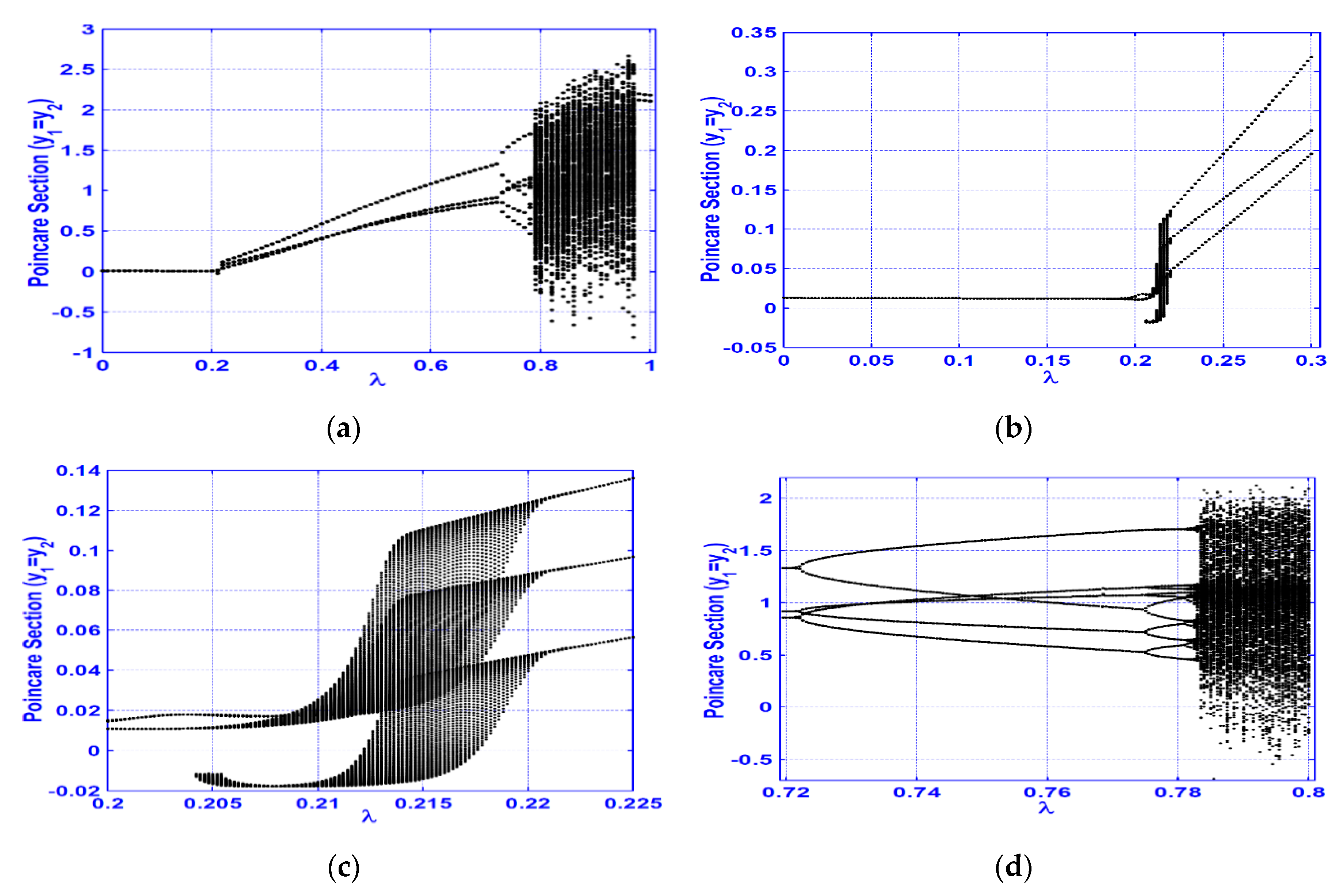
The bifurcation diagram at horizontal superharmonic resonance case Ω = 2 3 ω 1 is shown in Figure 3 utilizing λ as a bifurcation control parameter. The figure shows a rich bifurcation structure where period-doubling bifurcation occurs at   λ 0.7215 as in Figure 3a,d. It is clear from the figure that the system can perform period-1 motion as long as   λ < 0.192 , while at 0.192 λ 0.204 the system exhibits period-2 motion. Further increasing   λ , the system loses its periodical motion to respond with a quasi-periodic motion as long as   0.204 < λ 0.2206 . Moreover, when λ is beyond 0.2206 the system executes period-3 motion up to   λ = 0.7215 , beyond   λ = 0.7215 , period-doubling bifurcation occurs that is the route to chaotic motion where period-6, period-12, and period-24 are noticed in the interval   0.7215 < λ < 0.7835 . More increasing of the bifurcation control parameter causes the chaotic response of the system, which appears at the interval   0.7835 λ 0.97 , while at   λ > 0.97 the system goes again into its regular response with period-2 oscillation as long as   0.97 < λ 1 .
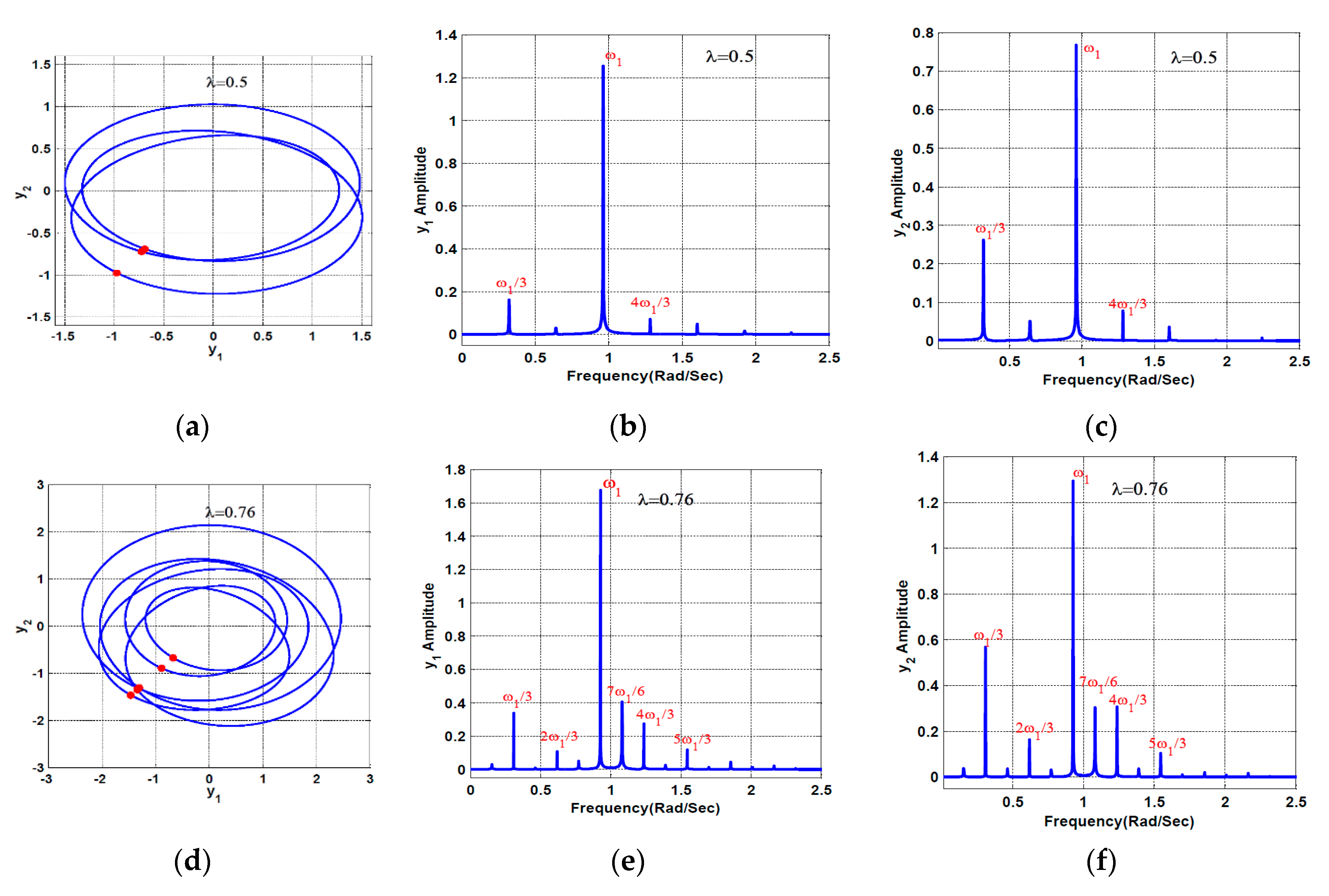
According to the bifurcation diagram given in Figure 3, the system whirling orbits, Poincaré map (red color), and the frequency spectrum of the cracked system when   λ = 0.5 ,   0.76 ,   0.8 , and 0.99 are illustrated in Figure 4. It is clear from the figure that the system can perform period-3 motion at the crack size   λ = 0.5 , period-6 motion at λ = 0.76 , chaotic motion at λ = 0.8 , and period-2 motion at λ = 0.99 . By comparing Figure 3 and Figure 4, one can notice the excellent correspondence between the two figures.
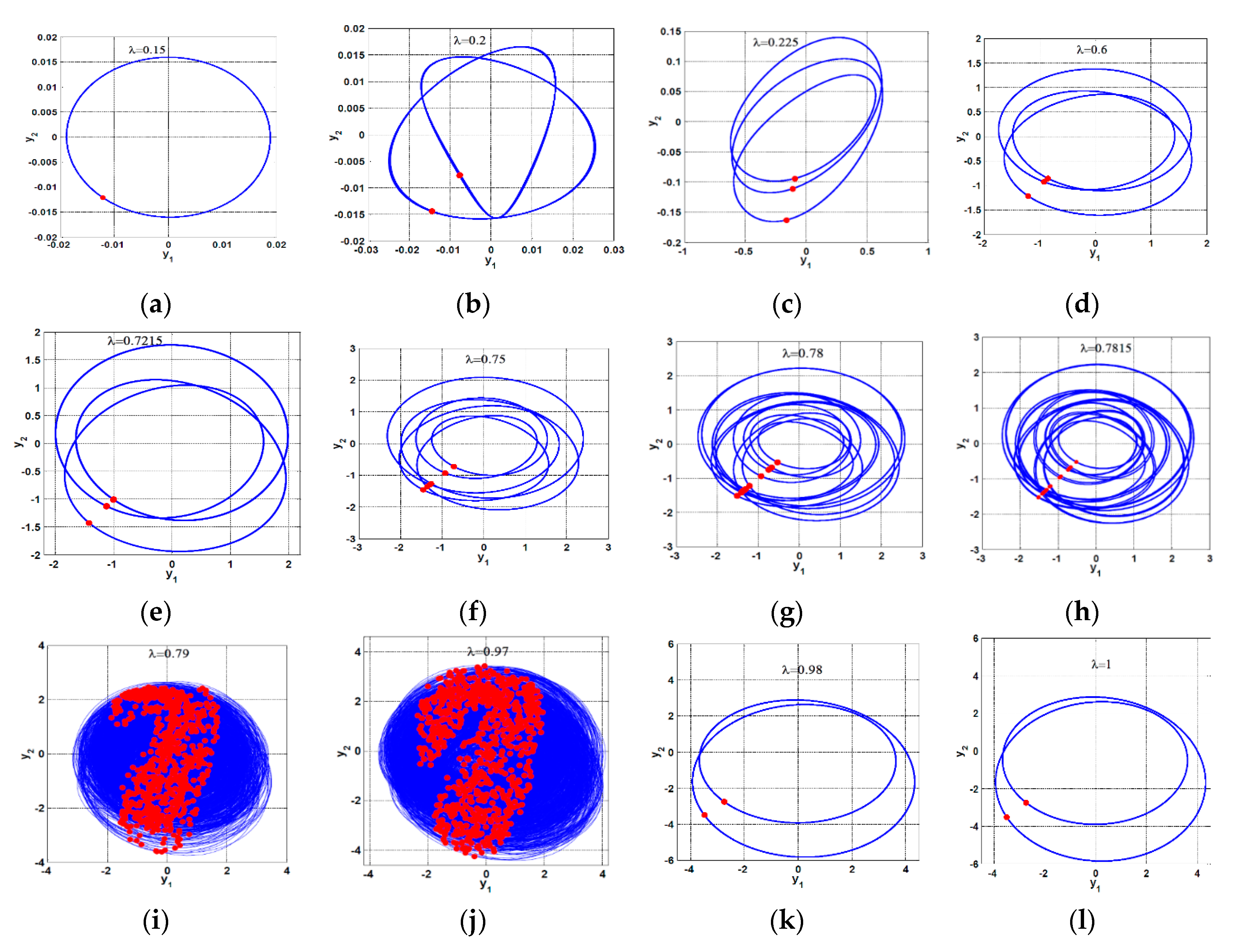
Figure 5 shows a full bifurcation scenario for the cracked shaft vibrations when increasing the crack size ( λ ) from   λ = 0.15 to λ = 1.0 according to the obtained results in Figure 3. It is noticed from Figure 5a that the cracked system can perform a period-1 motion as in the case of the intact system as long as   λ is within the interval   [ 0 ,   0.192 ) . Accordingly, it is not possible to distinguish between the cracked and intact system as long as the crack size   λ belongs to the interval   [ 0 ,   0.192 ) . However, if the considered system exhibits a period-2 motion having a small amplitude, this means that the crack size is within the interval   [ 0.192 ,   0.204 ] as shown in Figure 5b. In addition, when the system oscillates with quasi-periodic motion this implies that the value of the crack size may be within the range   [ 0.204 ,   0.2206 ] , while the system period-3 motion indicates that λ is within the interval ( 0.2206 ,   0.7215 ] as illustrated in Figure 5c–e. When the system responds with period-6 motion it confirms that λ is within the range ( 0.7215 ,   0.7745 ] , while the appearance of the period-12 (as in Figure 5g) or period-24 (as in Figure 5h) implies that λ is within the interval ( 0.7745 ,   0.781 ] or ( 0.781 ,   0.7825 ] , respectively. Moreover, the chaotic oscillations of the cracked shaft indicate that the crack size is within the range ( 0.7825 ,   0.97 ] as in Figure 5i,j, but when the system executes period-2 motion with high vibration amplitudes as in Figure 5k,l, this means that λ is within the range   ( 0.97 ,   1 ] . Accordingly, the noticed qualitative changes of the system motion as the bifurcation control parameter   λ increases may be utilized to predict the crack-size depending on the nature of the system motions and the corresponding vibration amplitudes. One of the important notes from Figure 4 and Figure 5 is the existence of an asymmetry in the system whirling orbit due to both the shaft weight and the shaft crack.
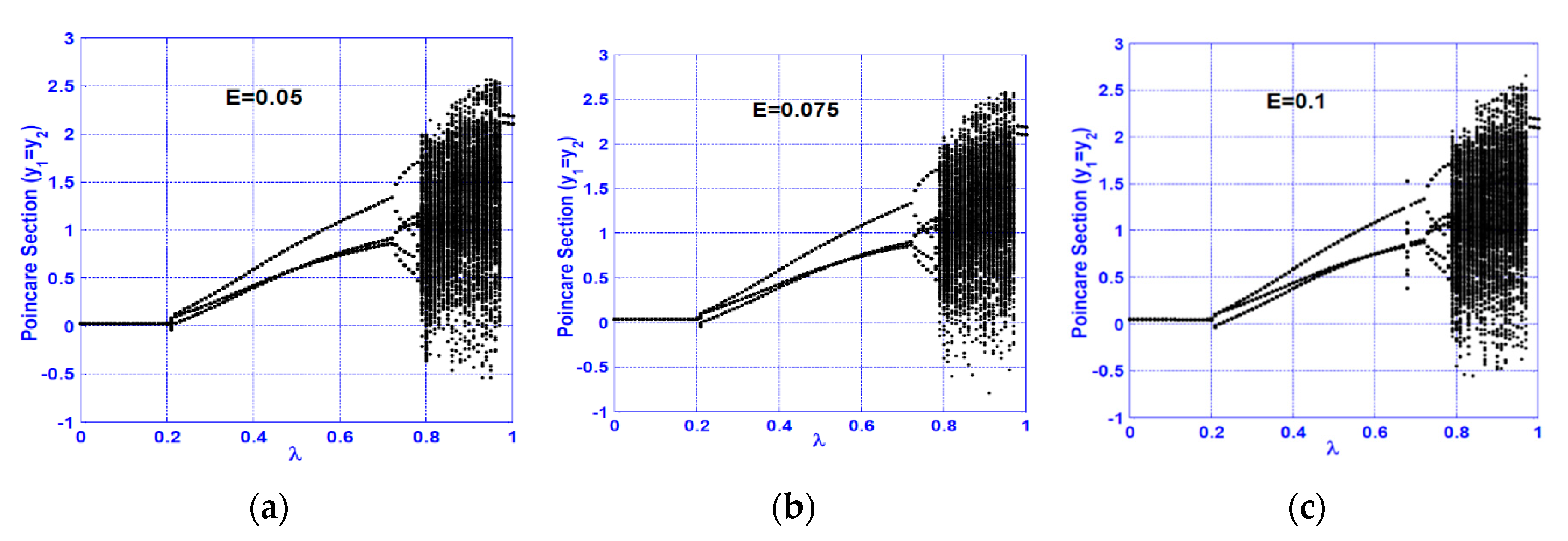
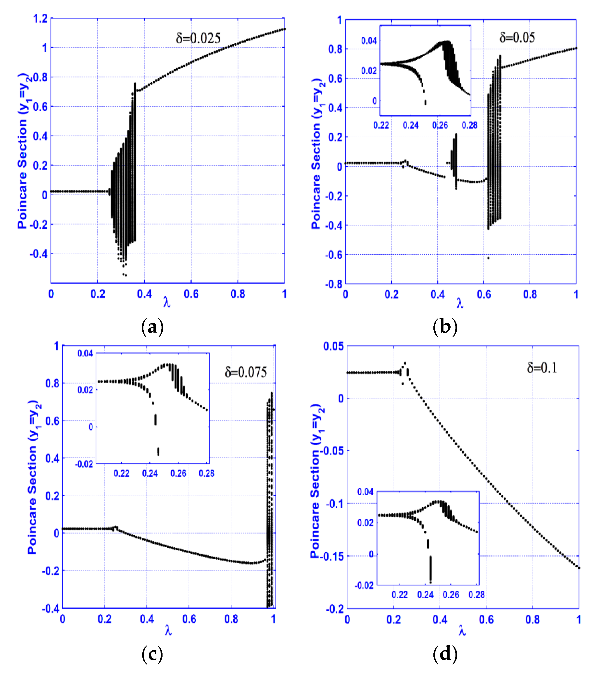
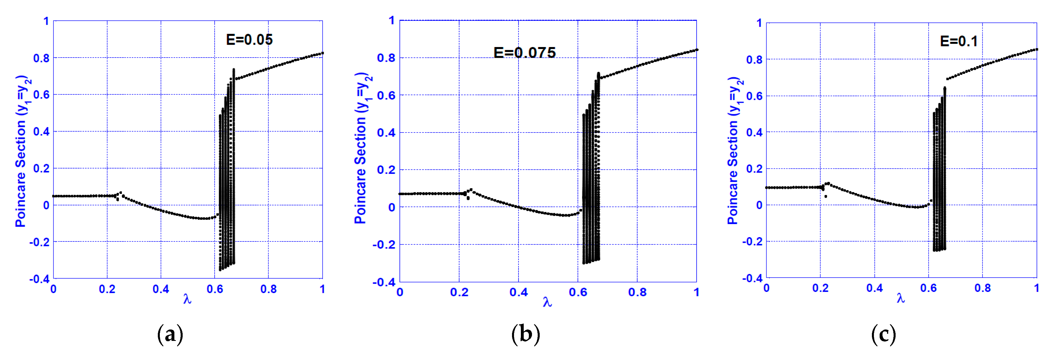
One of the main parameters whose magnitude may differ from one system to another is the disk eccentricity ( E ). Figure 6 shows the effect of increasing the disk eccentricity on the bifurcation diagram obtained in Figure 3, where Figure 6a–c shows the bifurcation diagrams at E = 0.05 ,   0.075 , and 0.1 , respectively. It is noticed from Figure 6 that the disk eccentricity has a negligible effect on the bifurcation diagrams for the superharmonic resonance case; that agrees with the results obtained by Saeed and Eissa [46]. The influences of nonlinearity magnitude ( δ ) on the bifurcation diagram are depicted in Figure 7. By tracking the bifurcation diagrams in Figure 7 as λ increases, it is found that the system follows the same bifurcation scenario regardless of the nonlinearity magnitude. However, the interval of λ at which the system may respond with period-1, period-3… etc., changes depending on the magnitude of   δ . Accordingly, Figure 6 and Figure 7 confirm the existence of continuous qualitative change for the system motion as the crack size increases at the horizontal superharmonic resonance case regardless of the eccentricity and nonlinearity magnitudes.

3.2. Vertical Superharmonic Resonance ( Ω = 2 3 ω 2 )

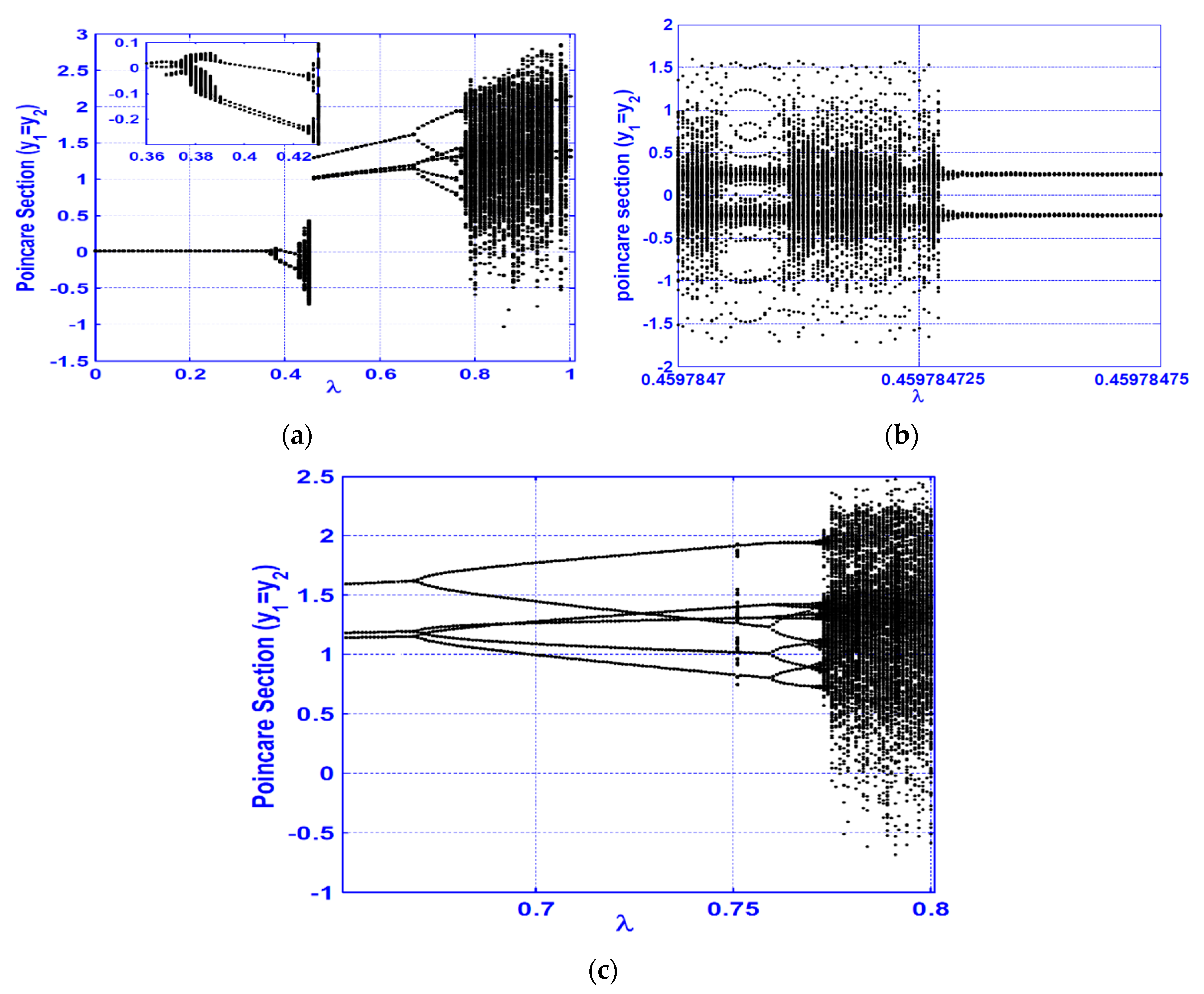
Within this section, bifurcation behaviors of the cracked system are analyzed at the vertical superharmonic resonance case (i.e.,   Ω = 2 3 ω 2 ). Figure 8 shows the system bifurcation diagram for the same values of system parameters that are utilized to obtain Figure 3. It is noticed from Figure 8 that the cracked system executes period-1 motion as long as   λ < 0.36 , while for   0.36 λ 0.366 , the system exhibits period-2 motion. Further increasing of   λ is resulting in losing the periodic motion, where the system responds with a quasi-periodic one as long as   0.366 < λ 0.39 . However, when 0.39 < λ 0.422 the system executes period-3 motion, but for 0.422 < λ 0.45 the system exhibits a quasi-periodic motion again. In addition, the system loses its chaotic motion via a period-halving bifurcation at the narrow interval   0.4597847 λ 0.45978475 as in Figure 8b to perform a period-3 motion at the interval   0.45 < λ 0.669 . Moreover, at λ = 0.669 a period-doubling bifurcation occurs leading to chaotic motion along the interval 0.773 λ 0.99 , where the increase of λ beyond   0.99 results in a regular period-3 motion again.
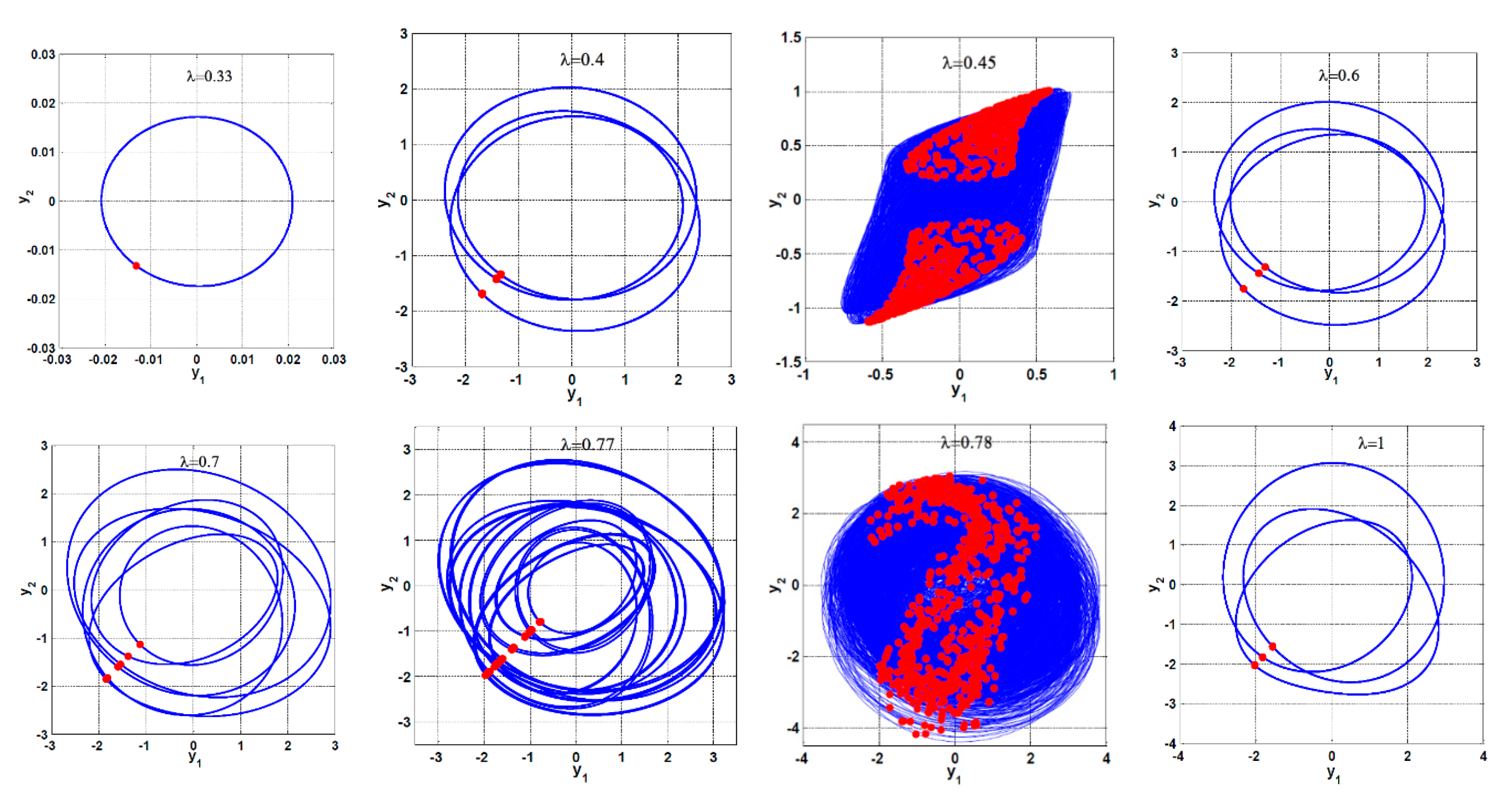
Figure 9 illustrates a complete bifurcation scenario via plotting the whirling orbits and the frequency spectrum of the considered system at the vertical superharmonic resonance according to Figure 8. The figures confirm the qualitative change of the system motion as   λ increases, where the system can execute period-3 motion at three different isolated ranges of the crack size (i.e., at 0.39 < λ 0.422 ,   0.45 < λ 0.669 , and λ > 0.99 ). By comparing the system bifurcation diagrams shown in Figure 3 and Figure 8, it is noticed that the system executes period-1 motion for λ < 0.192 at   Ω = 2 3 ω 1 , but at Ω = 2 3 ω 2 the system exhibits period-1 motion as long as   λ < 0.36 . Moreover, at the vertical superharmonic resonance, the system performs period-3 motion at three different isolated ranges of λ as shown in Figure 9 and Figure 10, which may be misleading for estimating the crack size. Accordingly, the system oscillations at horizontal superharmonic resonance are more sensitive to small crack sizes than is the case for the vertical superharmonic resonance.
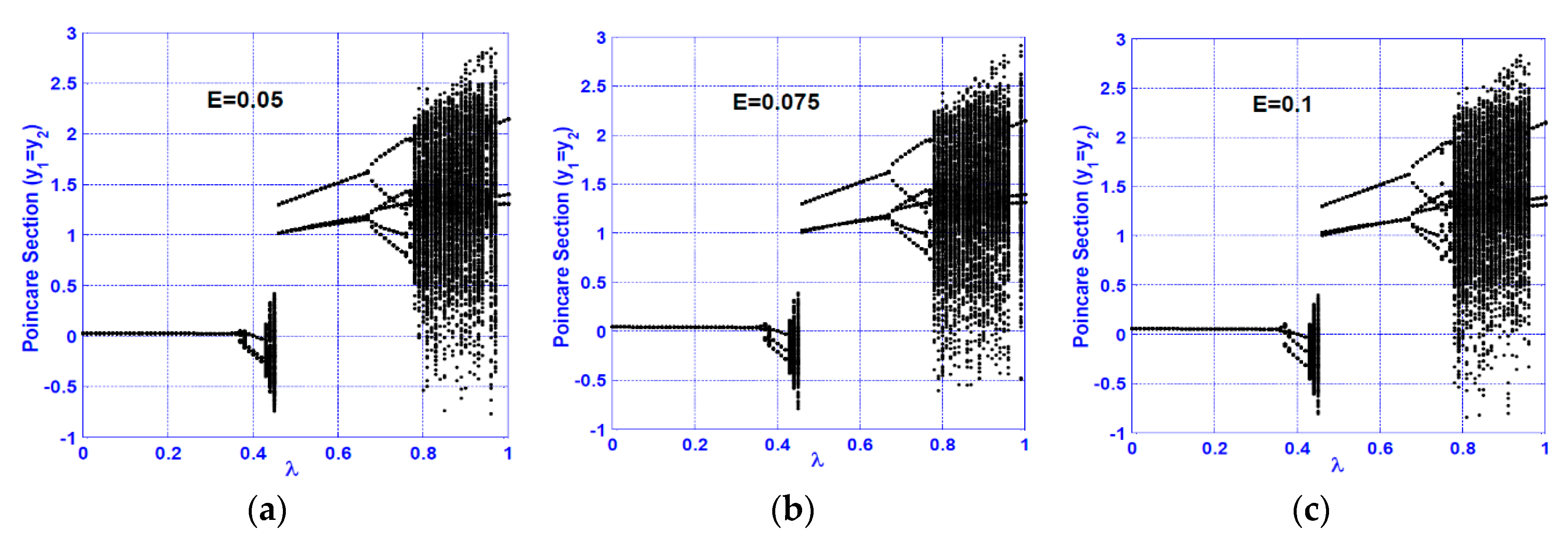
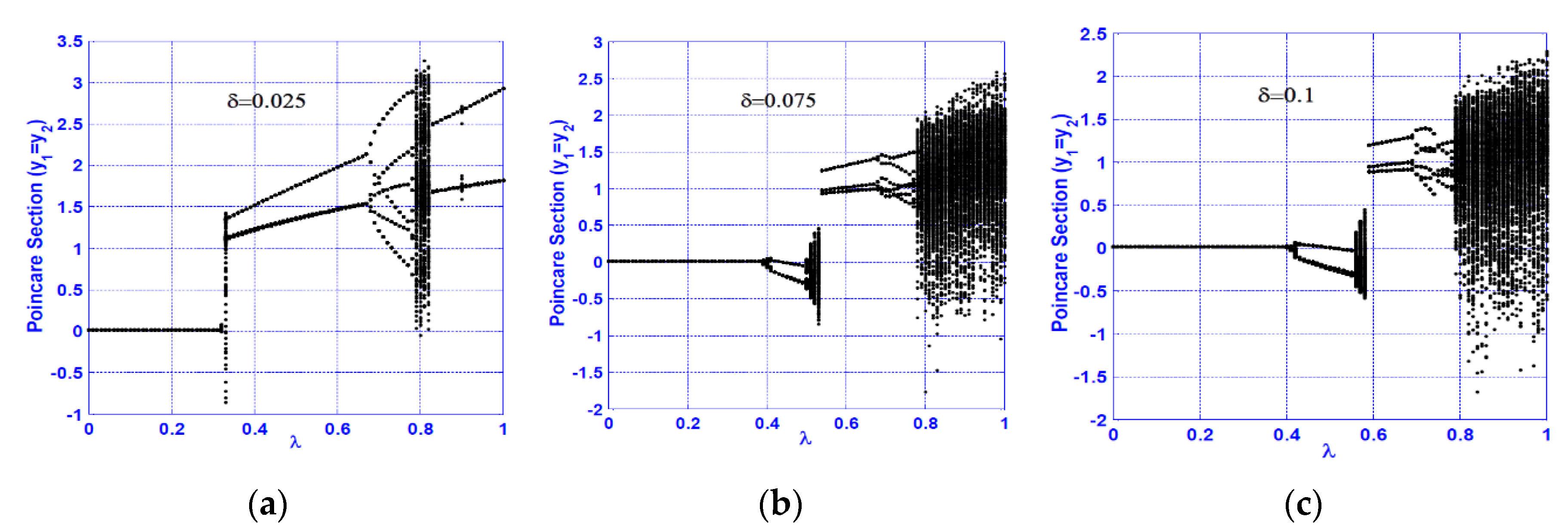
The influence of both disk eccentricity ( E ) and the nonlinearity coefficient ( δ ) on the bifurcation diagram at the vertical superharmonic resonance is illustrated in Figure 10 and Figure 11, respectively. It is clear from Figure 10 that there is a negligible effect from E on the bifurcation diagram, while δ has a noticeable influence on the system bifurcation scenario as shown in Figure 11.

3.3. Horizontal Subharmonic Resonance ( Ω = 2 ω 1 )

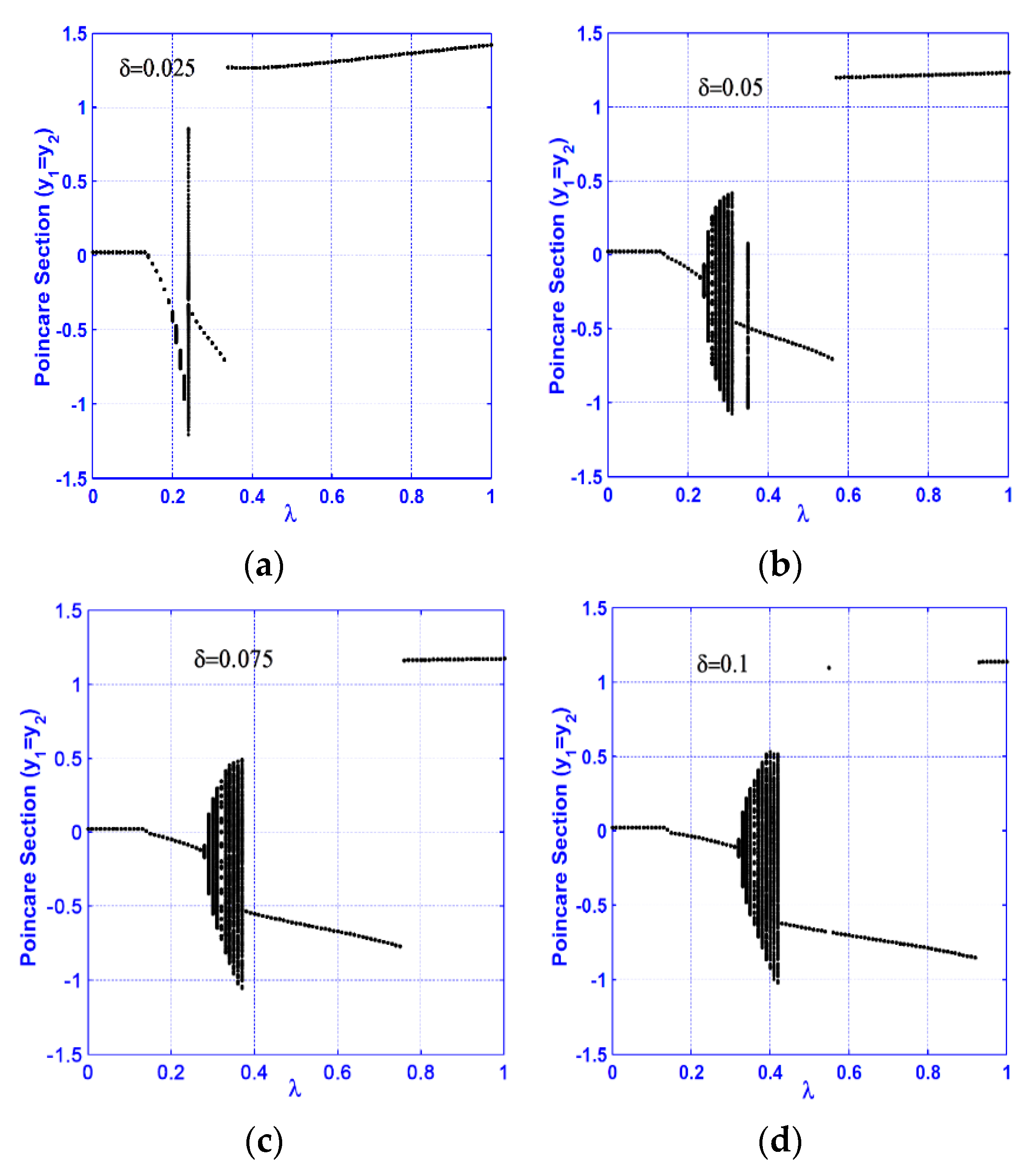
In this section, the considered system bifurcation diagram is analyzed at the horizontal subharmonic resonance case ( Ω = 2 ω 1 ). The effect of the nonlinearity coefficient ( δ ) on the bifurcation behaviors as the crack size increases is illustrated in Figure 12. The figure shows a simple bifurcation scenario for the cracked system, where the reported lateral vibrations are period-1, quasi-periodic, and sometimes period-2 motions, depending on the magnitude of δ . In addition, the dominant whirling motion for a wide range of crack sizes is period-1. Accordingly, it is not possible to utilize this resonance case (i.e.,   Ω = 2 ω 1 ) to characterize the crack size. It is worth mentioning that Figure 12a,b shows the origin of a torus bifurcation [57], where a sudden change from period-1 to the quasi-periodic motion has occurred during the increase of   λ .
A full bifurcation scenario for the system motion according to the bifurcations diagram in Figure 12b (i.e.,   δ = 0.05 ) is illustrated in Figure 13 when the crack size increases from λ = 0.2 to   λ = 0.61 . By comparing Figure 12b and Figure 13, one can find an excellent correspondence between the two figures. Figure 14 shows the effect of increasing the disk eccentricity ( E ) on the cracked system bifurcation diagram when   Ω = 2 ω 1 . The figure illustrates that an increase of E has a negligible effect on the bifurcation structure for the subharmonic resonance case, as reported in [46].

3.4. Vertical Subharmonic Resonance ( Ω = 2 ω 2 )

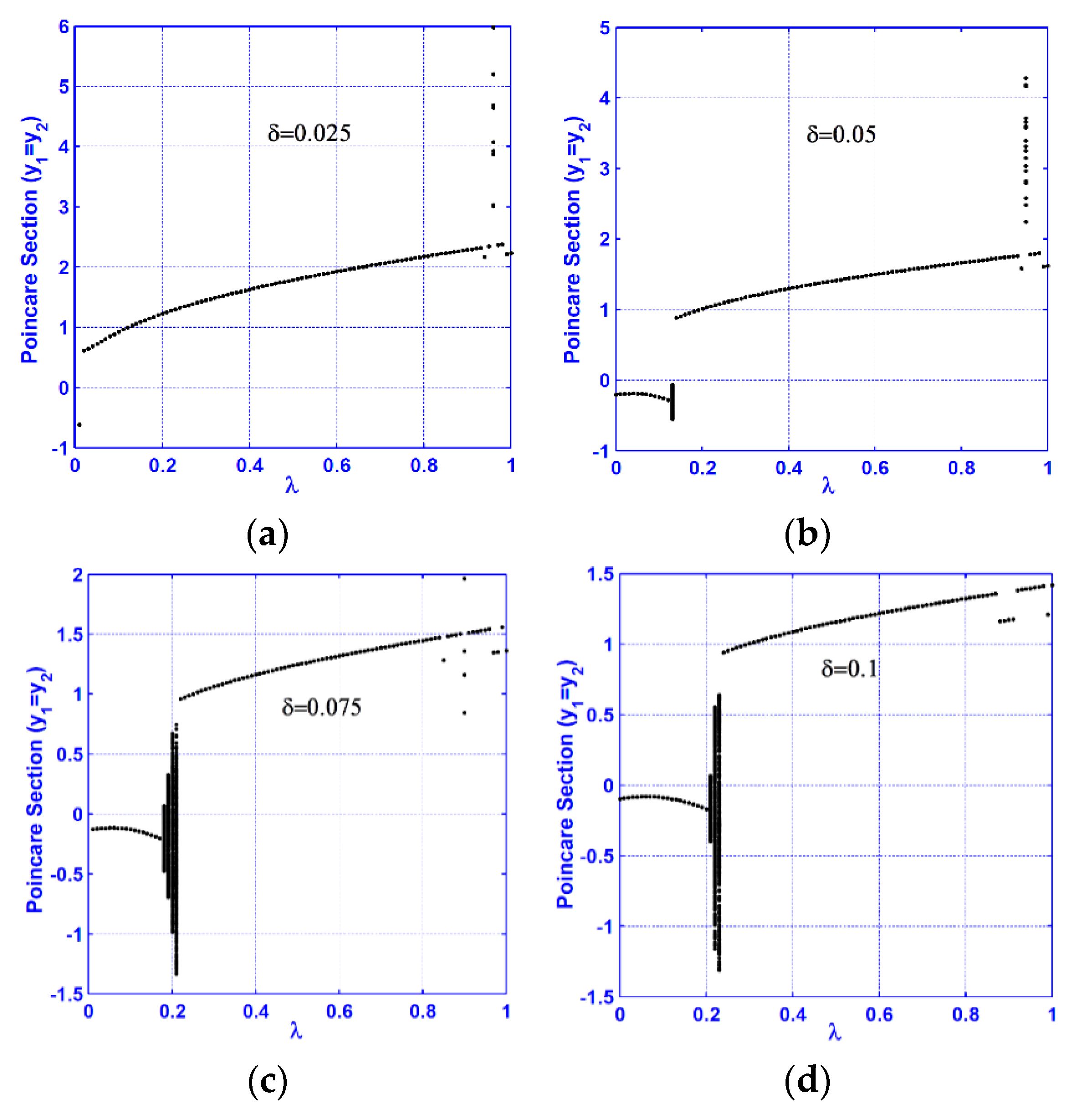
The system bifurcation behaviors for the vertical subharmonic resonance case ( Ω = 2 ω 2 ) are discussed in this section. Figure 15 illustrates the system bifurcation diagram at four different values of the nonlinearity coefficient ( δ ). In general, Figure 15 shows a simple bifurcation scenario, where the system executes period-1 motion as the crack size ( λ ) increases from zero to unity except at a small interval of λ where the system may exhibit quasi-periodic motion. In addition, Figure 16 confirms the negligible effects of increasing the disk eccentricity on the system bifurcation diagram for the vertical subharmonic resonance case.

3.5. Primary Resonance Cases ( Ω = ω 1 and Ω = ω 2 )

The bifurcation diagram at the horizontal primary resonance case ( Ω = ω 1 ) is illustrated in Figure 17 at four different values of the nonlinearity coefficient ( δ ). The figure shows that the system executes period-1 motion only, where there is no qualitative change for the system motion as the crack size increases. Figure 18 shows the effect of increasing the disk eccentricity on the system bifurcation diagram when   Ω = ω 1 . The figure illustrates that increasing the disk eccentricity does not influence the nature of the system motion and the system can perform a period-1 motion.
Figure 19 shows the system bifurcation diagrams at four different values of   δ when ( Ω = ω 2 ). The figure confirms that the system may perform period-1 motion only or both period-1 and quasi-periodic motions as the crack size increases, depending on the nonlinearity magnitude, where the system can perform period-1 motion only when the crack size increases from zero to unity at   δ = 0.025 , while at δ = 0.05 ,   0.075 and 0.1 , there is an interval of crack sizes λ at which the system can execute quasi-periodic motion as in Figure 19b–d. Finally, a summary for all obtained results is given in Table 1.

4. Conclusions

The main purpose of this research is to determine how to diagnose the existence of a transverse crack on the rotating shaft of a horizontally supported nonlinear Jeffcott rotor and how to predict its size via the dynamical interactions of the cracked system. A mathematical model governing the lateral vibrations of the considered system was derived, where the stiffness nonlinearity, shaft weight, shaft eccentricity, and breathing of the shaft crack are included. Applying asymptotic analyses, the nonlinear resonance cases were determined; namely the primary, superharmonic, and subharmonic resonance. Numerical exploration for the system lateral vibrations when the crack size increases is performed utilizing a bifurcation diagram, a frequency spectrum, a Poincaré map, and whirling-orbits. Influences of the disk eccentricity and the nonlinearity coefficient on the bifurcation diagram were investigated. Based on the obtained results, we may conclude the following remarks:
  • Increasing the disk eccentricity does not influence the nature of the system motions at superharmonic and subharmonic resonances, but it can increase the oscillation amplitude at the primary resonance case only.
  • The cracked system executes period-1 motions for different crack sizes for the horizontal primary resonance case, where there is no qualitative change for the system motion.
  • The system motions are mostly period-1 for different crack sizes at the vertical primary resonance. However, the system may execute quasi-periodic motion at specific ranges of the crack size depending on the nonlinearity magnitude.
  • In subharmonic resonance cases, the cracked system exhibits period-1 motion except at two isolated ranges of the crack size for which the system executes period-2 or quasi-periodic motion, depending on the nonlinearity magnitude.
  • A continuous qualitative change for the system motion is noticed as the crack size increases in the superharmonic resonance cases, where the system starts with period-1 motion, then exhibits period-2 followed by a quasi-periodic motion. The system exhibits period-3 motion followed by period-doubling bifurcation that led to a chaotic response, and finally, a sudden transition to the regular motion occurs.
  • The system vibration for the horizontal superharmonic resonance case is more sensitive to small crack sizes than in the vertical superharmonic resonance.
  • Based on the concluded points (1) to (6), the best resonance case that can be utilized to predict the crack size magnitude is the horizontal superharmonic resonance case (i.e., when Ω = 2 3 ω 1 ), in which when the crack size increases, the system executes period-1, period-2, quasi-periodic, period-3, period-doubling, chaotic, and period-2 motions, sequentially.

Author Contributions

N.A.S. developed the idea of this research and made the problem formulation; N.A.S. derived the formulas, made the calculations, and performed the simulation study; N.A.S., M.S.M., and S.K.E. oversaw all aspects of the research, data analysis, writing, and validation, prepared the initial draft of the paper, and revised this manuscript. All authors have read and agreed to the published version of the manuscript.

Funding

This paper was funded by Taif University Researchers Supporting Project Number (TURSP-2020/160), Taif University, Taif, Saudi Arabia.

Acknowledgments

The authors are thankful of the Taif University. Taif University researchers were supported by project number (TURSP-2020/160), Taif University, Taif, Saudi Arabia.

Conflicts of Interest

The authors declared no potential conflicts of interest concerning the research, authorships, and/or publication of this article Compliance with Ethical Standards.

Nomenclature

y 1 ,   y ˙ 1 , y ¨ 1 Displacement, velocity, and acceleration of the disk geometric center in the U 1 -direction.
y 2 ,   y ˙ 2 , y ¨ 2 Displacement, velocity, and acceleration of the disk geometric center in the U 2 -direction.
μ 1 ,   μ 2 Linear damping coefficients in the U 1 and   U 2 –directions, respectively.
ω 1 , ω 2     Linear natural frequencies of the horizontal and vertical directions, respectively.
δ Quadratic and cubic nonlinearities coefficient.
Ω Disk spinning speed.
E Disk-eccentricity magnitude.
λ A parameter representing the relative reduction of the shaft linear stiffness coefficient due to the crack.
γ Orientation angle between the crack and imbalance directions

Appendix A

Utilizing perturbation methods [58,59], one can obtain an approximate solutions to Equations (13) and (14) up to the second-order in the form:
y 1 ( t ; ε ) = ε y 11 ( T 0 , T 1 , T 2 ) + ε 2 y 12 ( T 0 , T 1 , T 2 ) + ε 3 y 13 ( T 0 , T 1 , T 2 ) + O ( ε 4 )
y 2 ( t ; ε ) = ε y 21 ( T 0 , T 1 , T 2 ) + ε 2 y 22 ( T 0 , T 1 , T 2 ) + ε 3 y 23 ( T 0 , T 1 , T 2 ) + O ( ε 4 )
where ε is a book-keeping dimensionless perturbation parameter, and T n = ε n t ,   n = 0 ,   1 ,   2 are fast and slow time scales. In terms of T 0 ,     T 1 , and T 2 , the time derivatives of Equations (13) and (14) can be expressed as:
d d t = D 0 + ε D 1 + ε 2 D 2 ,   d 2 d t 2 = D 0 2 + 2 ε D 0 D 1 + ε 2 ( D 1 2 + 2 D 2 D 0 ) ,         D j = T j ,                 j = 0 ,       1 ,     2  
Accordingly, the system parameters can be scaled as follows:
μ 1 = ε 2 μ ^ 1 ,           μ 2 = ε 2 μ ^ 2 ,         λ = ε 2 λ ^ ,         E = ε 3 E ^
Substituting Equations (A1)–(A4) into Equations (13) and (14) and equating coefficients of like powers of   ε , yields:
O ( ε 1 ):
( D 0 2 + ω 1 2 ) y 11 = 0
( D 0 2 + ω 2 2 ) y 21 = 0
O ( ε 2 ):
( D 0 2 + ω 1 2 ) y 12 = 2 D 0 D 1 y 11 2 δ y 21 y 11
( D 0 2 + ω 2 2 ) y 22 = 2 D 0 D 1 y 21 δ y 11 2 3   δ y 21 2
O ( ε 3 ):
( D 0 2 + ω 1 2 ) y 13 = 2 D 0 D 1 y 12 ( D 1 2 + 2 D 2 D 0 ) y 11 μ ^ 1 D 0 y 11 2 δ y 21 y 12 2 δ y 22 y 11 δ y 21 2 y 11 δ y 11 3   + E ^ Ω 2 cos ( Ω T 0 + γ ) + 1 8 λ ^ y 11 ( sin ( Ω T 0 ) + 2 cos ( 2 Ω T 0 ) sin ( 3 Ω T 0 ) )   1 8 λ ^ y 21 ( cos ( Ω T 0 ) 2 sin ( 2 Ω T 0 ) cos ( 3 Ω T 0 ) )
( D 0 2 + ω 2 2 ) y 23 = 2 D 0 D 1 y 22 ( D 1 2 + 2 D 2 D 0 ) y 21 μ ^ 2 D 0 y 21 2 δ y 11 y 12 6 δ y 21 y 22 δ y 21 y 11 2 δ y 21 3   + E ^ Ω 2 sin ( Ω T 0 + γ ) + 1 8 λ ^ y 21 ( 3 sin ( Ω T 0 ) 2 cos ( 2 Ω T 0 ) + sin ( 3 Ω T 0 ) )   1 8 λ ^ y 11 ( cos ( Ω T 0 ) 2 sin ( 2 Ω T 0 ) cos ( 3 Ω T 0 ) )
The solution of Equations (A5) and (A6), can be expressed as:
y 11 ( T 0 , T 1 , T 2 ) = A 1 ( T 1 , T 2 ) e i ω 1 T 0 + A 1 ¯ ( T 1 , T 2 ) e i ω 1 T 0
y 21 ( T 0 , T 1 , T 2 ) = A 2 ( T 1 , T 2 ) e i ω 2 T 0 + A 2 ¯ ( T 1 , T 2 ) e i ω 2 T 0
The coefficients   A 1 ( T 1 , T 2 ) and   A 2 ( T 1 , T 2 ) are unknown functions of   T 1 , and T 2 . Substituting Equations (A11) and (A12) into Equations (A7) and (A8), yields:
( D 0 2 + ω 1 2 ) y 12 = 2 i ω 1 e i ω 1 T 0 D 1 A 1 + 2 i ω 1 e i ω 1 T 0 D 1 A 1 ¯ 2 δ A 1 A 2 e i ( ω 1 + ω 2 ) T 0 2 δ A 1 ¯ A 2 ¯ e i ( ω 1 + ω 2 ) T 0   2 δ A 1 ¯ A 2 e i ( ω 1 + ω 2 ) T 0 2 δ A 1 A 2 ¯ e i ( ω 1 ω 2 ) T 0
( D 0 2 + ω 2 2 ) y 2 2 = 2 i ω 2 e i ω 2 T 0 D 1 A 2 + 2 i ω 2 e i ω 2 T 0 D 1 A 2 ¯ δ ( A 1 2 e 2 i ω 1 T 0 + A 1 ¯ 2 e 2 i ω 1 T 0 + 2 A 1 A 1 ¯ )   3   δ ( A 2 2 e 2 i ω 2 T 0 + A 2 ¯ 2 e 2 i ω 2 T 0 + 2 A 2 A 2 ¯ )
The solvability conditions for Equations (A13) and (A14) are:
D 1 A 1 = 0 ,     D 1 A 2 = 0 A 1 ( T 1 , T 2 ) = A 1 ( T 2 ) ,       A 2 ( T 1 , T 2 ) = A 2 ( T 2 )
Accordingly, the solutions of Equations (A13) and (A14) are given as:
y 12 ( T 0 , T 2 ) = 2 δ ω 2 ( 2 ω 1 + ω 2 ) ( A 1 A 2 e i ( ω 1 + ω 2 ) T 0 + A 1 ¯ A 2 ¯ e i ( ω 1 + ω 2 ) T 0 ) + 2 δ ω 2 ( ω 2 2 ω 1 ) ( A 1 ¯ A 2 e i ( ω 1 ω 2 ) T 0   + A 1 A 2 ¯ e i ( ω 1 ω 2 ) T 0 )
y 22 ( T 0 , T 2 ) = δ 4 ω 1 2 ω 2 2 ( A 1 2 e 2 i ω 1 T 0 + A 1 ¯ 2 e 2 i ω 1 T 0 ) +   δ ω 2 2 ( A 2 2 e 2 i ω 2 T 0 + A 2 ¯ 2 e 2 i ω 2 T 0 ) 2 δ ω 2 2 A 1 A 1 ¯ 6   δ ω 2 2 A 2 A 2 ¯
Substituting Equations (A11), (A12), (A16) and (A17) into Equations (A9) and (A10), we have
( D 0 2 + ω 1 2 ) y 13 = 2 i ω 1 e i ω 1 T 0 D 2 A 1 i μ ^ 1 ω 1 A 1 e i ω 1 T 0 ( 4 δ 2 ω 2 ( 2 ω 1 + ω 2 ) + 4 δ 2 ω 2 ( ω 2 2 ω 1 ) 12 δ 2 ω 2 2   + 2 δ ) A 1 A 2 A 2 ¯ e i ω 1 T 0 ( 2 δ 2 4 ω 1 2 ω 2 2 4 δ 2 ω 2 2 + 3 δ ) A 1 2 A 1 ¯ e i ω 1 T 0 ( 4 δ 2 ω 2 ( ω 2 2 ω 1 ) +   2 δ 2 ω 2 2   + δ ) A 1 ¯ A 2 2 e i ( ω 1 2 ω 2 ) T 0 ( 4 δ 2 ω 2 ( 2 ω 1 + ω 2 ) +   2 δ 2 ω 2 2 + δ ) A 1 A 2 2 e i ( ω 1 + 2 ω 2 ) T 0 ( 2 δ 2 4 ω 1 2 ω 2 2   + δ ) A 1 3 e 3 i ω 1 T 0 + 1 2 E ^ Ω 2 e i ( Ω T 0 + γ ) + 1 16 λ ^ A 1 ( i e i ( Ω + ω 1 ) T 0 + 2 e i ( 2 Ω + ω 1 ) T 0 + i e i ( 3 Ω + ω 1 ) T 0 )   + 1 16 λ ^ A 1 ¯ ( i e i ( Ω ω 1 ) T 0 + 2 e i ( 2 Ω ω 1 ) T 0 + i e i ( 3 Ω ω 1 ) T 0 ) 1 16 λ ^ A 2 ( e i ( Ω + ω 2 ) T 0 + 2 i e i ( 2 Ω + ω 2 ) T 0   e i ( 3 Ω + ω 2 ) T 0 ) 1 16 λ ^ A 2 ¯ ( e i ( Ω ω 2 ) T 0 + 2 i e i ( 2 Ω ω 2 ) T 0 e i ( 3 Ω ω 2 ) T 0 ) + c c
( D 0 2 + ω 2 2 ) y 23 = 2 i ω 2 e i ω 2 T 0 D 2 A 2 i μ ^ 2 ω 2 A 2 e i ω 2 T 0 ( 4 δ 2 ω 2 ( 2 ω 1 + ω 2 ) + 4 δ 2 ω 2 ( ω 2 2 ω 1 ) 12 δ 2 ω 2 2   + 2 δ ) A 1 A 1 ¯ A 2 e i ω 2 T 0 ( 4 δ 2 ω 2 ( 2 ω 1 + ω 2 ) + 6 δ 2 4 ω 1 2 ω 2 2 + δ ) A 1 2 A 2 e i ( 2 ω 1 + ω 2 ) T 0 ( 4 δ 2 ω 2 ( ω 2 2 ω 1 )   + 6 δ 2 4 ω 1 2 ω 2 2 + δ ) A 1 2 A 2 ¯ e i ( 2 ω 1 ω 2 ) T 0 + ( 30   δ 2 ω 2 2 3 δ ) A 2 2 A 2 ¯ e i ω 2 T 0 (   6 δ 2 ω 2 2 + δ ) A 2 3 e 3 i ω 2 T 0   i 2 E ^ Ω 2 e i ( Ω T 0 + γ ) + 1 16 λ ^ A 2 ( 3 i e i ( Ω + ω 2 ) T 0 2 e i ( 2 Ω + ω 2 ) T 0 i e i ( 3 Ω + ω 2 ) T 0 ) + 1 16 λ ^ A 2 ¯ ( 3 i e i ( Ω ω 2 ) T 0   2 e i ( 2 Ω ω 2 ) T 0 i e i ( 3 Ω ω 2 ) T 0 ) 1 16 λ ^ A 1 ( e i ( Ω + ω 1 ) T 0 + 2 i e i ( 2 Ω + ω 1 ) T 0 e i ( 3 Ω + ω 1 ) T 0 ) 1 16 λ ^ A 1 ¯ ( e i ( Ω ω 1 ) T 0   + 2 i e i ( 2 Ω ω 1 ) T 0 e i ( 3 Ω ω 1 ) T 0 ) + c c
According to Equations (A18) and (A19), the system resonance cases are the primary resonances ( Ω ω 1 and   Ω ω 2 ), superharmonic resonances ( Ω 2 3 ω 1 and   Ω 2 3 ω 2 ), and subharmonic resonances ( Ω 2 ω 1 and   Ω 2 ω 2 ) cases.

References

  1. Ganesan, R. Dynamic response and stability of a rotor support system with non-symmetric bearing clearances. Mech. Mach. Theory 1996, 31, 781–798. [Google Scholar] [CrossRef]
  2. Kim, Y.; Noah, S. Quasi-periodic response and stability analysis for a non-linear Jeffcott rotor. J. Sound Vib. 1996, 190, 239–253. [Google Scholar] [CrossRef]
  3. Yabuno, H.; Kashimura, T.; Inoue, T.; Ishida, Y. Nonlinear normal modes and primary resonance of horizontally supported Jeffcott rotor. Nonlinear Dyn. 2011, 66, 377–387. [Google Scholar] [CrossRef]
  4. Saeed, N.A.; El-Gohary, H.A. On the nonlinear oscillations of a horizontally supported Jeffcott rotor with a nonlinear restoring force. Nonlinear Dyn. 2017, 88, 293–314. [Google Scholar] [CrossRef]
  5. Saeed, N.A. On vibration behavior and motion bifurcation of a nonlinear asymmetric rotating shaft. Arch. Appl. Mech. 2019, 89, 1899–1921. [Google Scholar] [CrossRef]
  6. Saeed, N.A. On the steady-state forward and backward whirling motion of asymmetric nonlinear rotor system. Eur. J. Mech. A Solids 2020, 80, 103878. [Google Scholar] [CrossRef]
  7. Huang, J.; Luo, A.C.J. Periodic Motions and Bifurcation Trees in a Buckled, Nonlinear Jeffcott Rotor System. Int. J. Bifurc. Chaos 2015, 25, 1550002. [Google Scholar] [CrossRef]
  8. Huang, J.; Luo, A.C.J. Analytical solutions of period-1 motions in a buckled, nonlinear Jeffcott rotor system. Int. J. Dyn. Control 2016, 4, 376–383. [Google Scholar] [CrossRef]
  9. Xu, Y.; Chen, Z.; Luo, A.C.J. On bifurcation trees of period-1 to period-2 motions in a nonlinear Jeffcott rotor system. Int. J. Mech. Sci. 2019, 160, 429–450. [Google Scholar] [CrossRef]
  10. Xu, Y.; Chen, Z.; Luo, A.C.J. An independent period-3 motion to chaos in a nonlinear flexible rotor system. Int. J. Dyn. Control 2020, 8, 337–351. [Google Scholar] [CrossRef]
  11. Xu, Y.; Chen, Z.; Luo, A.C.J. Period-1 Motion to Chaos in a Nonlinear Flexible Rotor System. Int. J. Bifurc. Chaos 2020, 30, 2050077. [Google Scholar] [CrossRef]
  12. Xu, Y.; Luo, A.C.J. Period-1 to period-8 motions in a nonlinear Jeffcott rotor system. J. Comput. Nonlinear Dyn. 2020, 15, 091012. [Google Scholar] [CrossRef]
  13. Ishida, Y.; Inoue, T. Vibration Suppression of nonlinear rotor systems using a dynamic damper. J. Vib. Control 2007, 13, 1127–1143. [Google Scholar] [CrossRef]
  14. Eissa, M.; Saeed, N.A.; El-Ganini, W.A. Saturation-based active controller for vibration suppression of a four-degree-of-freedom rotor–AMB system. Nonlinear Dyn. 2014, 76, 743–764. [Google Scholar] [CrossRef]
  15. Saeed, N.A.; Kamel, M. Nonlinear PD-controller to suppress the nonlinear oscillations of horizontally supported Jeffcott-rotor system. Int. J. NonLinear Mech. 2016, 87, 109–124. [Google Scholar] [CrossRef]
  16. Saeed, N.A.; El-Ganaini, W.A. Time-delayed control to suppress the nonlinear vibrations of a horizontally suspended Jeffcott-rotor system. Appl. Math. Model. 2017, 44, 523–539. [Google Scholar] [CrossRef]
  17. Saeed, N.A.; El-Ganaini, W.A. Utilizing time-delays to quench the nonlinear vibrations of a two-degree-of-freedom system. Meccanica 2017, 52, 2969–2990. [Google Scholar] [CrossRef]
  18. Saeed, N.A.; Kamel, M. Active magnetic bearing-based tuned controller to suppress lateral vibrations of a nonlinear Jeffcott-rotor system. Nonlinear Dyn. 2017, 90, 457–478. [Google Scholar] [CrossRef]
  19. Eissa, M.; Saeed, N.A. Nonlinear vibration control of a horizontally supported Jeffcott-rotor system. J. Vib. Control 2018, 24, 5898–5921. [Google Scholar] [CrossRef]
  20. Mobayen, S.; Ma, J. Robust finite-time composite nonlinear feedback control for synchronization of uncertain chaotic systems with nonlinearity and time-delay. Chaos Solitons Fractals 2018, 114, 46–54. [Google Scholar] [CrossRef]
  21. Mofid, O.; Mobayen, S.; Khooban, M.H. Sliding mode disturbance observer control based on adaptive synchronization in a class of fractional-order chaotic systems. Int. J. Adapt Control Signal Process 2019, 33, 462–474. [Google Scholar] [CrossRef]
  22. Vaseghi, B.; Pourmina, M.A.; Mobayen, S. Finite-time chaos synchronization and its application in wireless sensor networks. Transact. Inst. Meas. Control 2018, 40, 3788–3799. [Google Scholar] [CrossRef]
  23. Mobayen, S.; Vaidyanathan, S.; Sambas, A.; Kaçar, S.; Çavusoglu, U. A Novel Chaotic System with Boomerang-Shaped Equilibrium, Its Circuit Implementation and Application to Sound Encryption. Iran. J. Sci. Technol. Trans. Electr. Eng. 2019, 43, 1–12. [Google Scholar] [CrossRef]
  24. Wauer, J. On the dynamics of cracked rotors: Literature survey. Appl. Mech. Rev. 1990, 43, 13–17. [Google Scholar] [CrossRef]
  25. Dimarogonas, A. Vibration of cracked structures: A state of the art review. Eng. Fract. Mech. 1996, 55, 831–857. [Google Scholar] [CrossRef]
  26. Gasch, R. A survey of the dynamic behavior of a simple rotating shaft with a transverse crack. J. Sound Vib. 1993, 160, 313–332. [Google Scholar] [CrossRef]
  27. Jun, O.S.; Eun, H.J.; Earmme, Y.Y.; Lee, C.W. Modelling and vibration analysis of a simple rotor with breathing crack. J. Sound Vib. 1992, 155, 273–290. [Google Scholar] [CrossRef]
  28. Sinou, J.-J.; Lees, A.W. The influence of cracks in rotating shafts. J. Sound Vib. 2005, 285, 1015–1037. [Google Scholar] [CrossRef] [Green Version]
  29. Sinou, J.-J. Effects of a crack on the stability of a non-linear rotor system. Int. J. Nonlinear Mech. 2007, 42, 959–972. [Google Scholar] [CrossRef] [Green Version]
  30. Sinou, J.-J.; Lees, A.W. A non-linear study of a cracked rotor. Eur. J. Mech. A Solids 2007, 26, 152–170. [Google Scholar] [CrossRef] [Green Version]
  31. Sinou, J.-J. Detection of cracks in rotor based on the 2× and 3× super-harmonic frequency components and the crack unbalance interactions. Commun. Nonlinear Sci. Numer. Simul. 2008, 13, 2024–2040. [Google Scholar] [CrossRef] [Green Version]
  32. Chen, C.; Dai, L.; Fu, Y. Nonlinear response and dynamic stability of a cracked rotor. Commun. Nonlinear Sci. Numer. Simul. 2007, 12, 1023–1037. [Google Scholar] [CrossRef]
  33. Han, Q.K.; Chu, F.L. Parametric instability of a rotor bearing system with two breathing transverse cracks. Eur. J. Mech. A Solids 2012, 36, 180–190. [Google Scholar] [CrossRef]
  34. Khorrami, H.; Rakheja, S.; Sedaghati, R. Vibration behavior of a two-crack shaft in a rotor disc-bearing system. Mech. Mach. Theory 2017, 113, 67–84. [Google Scholar] [CrossRef]
  35. Dai, L.M.; Chen, C.P. Dynamic stability analysis of a cracked nonlinear rotor system subjected to periodic excitations in machining. J. Vib. Control 2007, 13, 537–556. [Google Scholar] [CrossRef]
  36. Lin, Y.; Chu, F. Numerical and experimental investigations of flexural vibrations of a rotor system with transverse or slant crack. J. Sound Vib. 2009, 324, 107–125. [Google Scholar] [CrossRef]
  37. AL-Shudeifat, M.A.; Butcher, E.A.; Stern, C.R. General harmonic balance solution of a cracked rotor-bearing-disc system for harmonic and sub-harmonic analysis: Analytical and experimental approach. Int. J. Eng. Sci. 2010, 48, 921–935. [Google Scholar] [CrossRef]
  38. Yongcun, C.; Sier, D.; Wenhu, Z.; Guoding, C. The impact of roller dynamic unbalance of high-speed cylindrical roller bearing on the cage nonlinear dynamic characteristics. Mech. Mach. Theory 2017, 118, 65–83. [Google Scholar] [CrossRef]
  39. Gritli, H.; Belghith, S. Diversity in the nonlinear dynamic behavior of a one-degree-of-freedom impact mechanical oscillator under OGY-based state-feedback control law: Order, chaos and exhibition of the border-collision bifurcation. Mech. Mach. Theory 2018, 124, 1–41. [Google Scholar] [CrossRef]
  40. Tian, Q.; Flores, P.; Lankarani, H.M. A comprehensive survey of the analytical, numerical and experimental methodologies for dynamics of multibody mechanical systems with clearance or imperfect joints. Mech. Mach. Theory 2018, 122, 1–57. [Google Scholar] [CrossRef]
  41. Jun, O.S.; Gadala, M.S. Dynamic behavior analysis of cracked rotor. J. Sound Vib. 2008, 309, 210–245. [Google Scholar] [CrossRef]
  42. Jun, O.S. Dynamic behavior analysis of cracked rotor based on harmonic motion. Mech. Syst. Signal Process. 2012, 30, 186–203. [Google Scholar] [CrossRef]
  43. Ishida, Y. Cracked rotors Industrial machine case histories and nonlinear effects shown by simple Jeffcott rotor. Mech. Syst. Signal Process. 2008, 22, 805–817. [Google Scholar] [CrossRef]
  44. Hou, L.; Chen, Y.; Lu, Z.; Li, Z. Bifurcation analysis for 2:1 and 3:1 super-harmonic resonances of an aircraft cracked rotor system due to maneuver load. Nonlinear Dyn. 2015, 81, 531–547. [Google Scholar] [CrossRef]
  45. Cheng, L.; Li, N.; Chen, X.F.; He, Z.J. The influence of crack breathing and imbalance orientation angle on the characteristics of the critical speed of a cracked rotor. J. Sound Vib. 2011, 330, 2031–2048. [Google Scholar] [CrossRef]
  46. Saeed, N.A.; Eissa, M. Bifurcations of periodic motion of a horizontally supported nonlinear Jeffcott rotor system having transversely cracked shaft. Int. J. Nonlinear Mech. 2018, 101, 113–130. [Google Scholar] [CrossRef]
  47. Saeed, N.A.; Eissa, M. Bifurcation analysis of a transversely cracked nonlinear Jeffcott rotor system at different resonance cases. Int. J. Acoust. Vib. 2019, 24, 284–302. [Google Scholar] [CrossRef]
  48. Quinn, D.D.; Mani, G.; Kasarda, M.E.F.; Bash, T.; Inman, D.J.; Kirk, R.G. Damage detection of a rotating cracked shaft using an active magnetic bearing as a force actuator—analysis and experimental verification. IEEE/ASME Transact. Mech. 2005, 10, 640–647. [Google Scholar] [CrossRef]
  49. Hu, H.; Dong, G.; Peng, B.; Xing, J.; Song, W. Method for detecting micron cracks on a magnetic rotor surface based on a support vector machine. IEEE Access 2018, 6, 53141–53152. [Google Scholar] [CrossRef]
  50. Dong, Y.; Wang, J.; Wang, Z.F.; Zhang, X.; Gao, Y.; Sui, Q.; Jiang, P. A Deep-learning-based multiple defect detection method for tunnel lining damages. IEEE Access 2019, 7, 182643–182657. [Google Scholar] [CrossRef]
  51. Shen, Y.; Zhang, X.; Jiang, H.; Zhou, J.; Qiao, S.; Wang, C.; Ma, T. Comparative study on dynamic characteristics of two-stage gear system with gear and shaft cracks considering the shaft flexibility. IEEE Access 2020, 8, 133681–133699. [Google Scholar] [CrossRef]
  52. Hou, L.; Chen, Y.; Cao, Q.; Lu, Z. Nonlinear vibration analysis of a cracked rotor-ball bearing system during flight maneuvers. Mech. Mach. Theory 2016, 105, 515–528. [Google Scholar] [CrossRef]
  53. Nayfeh, A.H.; Ramachandran, B. Applied Nonlinear Dynamics: Analytical, Computational, and Experimental Methods; Wiley-VCH: Weinheim, Germany, 2004. [Google Scholar]
  54. Chávez, J.P.; Hamaneh, V.V.; Wiercigroch, M. Modelling and experimental verification of an asymmetric Jeffcott rotor with radial clearance. J. Sound Vib. 2015, 334, 86–97. [Google Scholar]
  55. Chang-Jian, C.-W.; Chen, C.-K. Couple stress fluid improve rub-impact rotor-bearing system–Nonlinear dynamic analysis. Appl. Math. Model. 2010, 34, 1763–1778. [Google Scholar] [CrossRef]
  56. Karpenko, E.V.; Wiercigroch, M.; Pavlovskaia, E.E.; Neilson, R.D. Experimental verification of Jeffcott rotor model with preloaded snubber ring. J. Sound Vib. 2006, 298, 907–917. [Google Scholar] [CrossRef]
  57. Gritli, H.; Belghith, S. Displayed phenomena in the semi-passive torso-driven biped model under OGY based control method: Birth of atorus bifurcation. Appl. Math. Model. 2016, 40, 2946–2967. [Google Scholar] [CrossRef]
  58. Nayfeh, A. Resolving controversies in the application of the method of multiple scales and the generalized method of averaging. Nonlinear Dyn. 2005, 40, 61–102. [Google Scholar] [CrossRef]
  59. Nayfeh, A.; Mook, D. Nonlinear Oscillations; Wiley: New York, NY, USA, 1995. [Google Scholar]
Figure 1. (a) Jeffcott-rotor system, (b) coordinate system of the disk, and (c) schematic diagram of the cracked shaft cross-section.
Symmetry 12 02059 g001
Figure 2. Model of stiffness-variation for the breathing crack.
Symmetry 12 02059 g002
Figure 3. System bifurcation diagrams for E = 0.025 and δ = 0.05 at Ω = 2 3 ω 1 : (a) bifurcation diagram, (b) zooming of (a) for 0 λ 0.3 , (c) zooming of (a) for   0.2 λ 0.225 , and (d) zooming of (a) for   0.721 λ 0.8 .
Symmetry 12 02059 g003
Figure 4. System whirling orbits, Poincaré map (red color), and frequency spectrum according to the bifurcation diagram given in Figure 3 (i.e.,   E = 0.025 and   δ = 0.05 ): (ac) period-3 motion at   λ = 0.5 , (df) period-6 motion at λ = 0.76 , (gi) chaotic motion at λ = 0.8 , and (jl) period-2 motion at   λ = 0.99 .
Symmetry 12 02059 g004aSymmetry 12 02059 g004b
Figure 5. System whirling orbits (blue color) and Poincaré map (red color) according to the bifurcation diagram given in Figure 3 (i.e.,   E = 0.025 and δ = 0.05 ) at different values of λ : (a) period-1, (b) period-2, (ce) period-3, (f) period-6, (g) period-12, (h) period-24, and (i,j) chaos, (k,l) period-2.
Symmetry 12 02059 g005
Figure 6. Influences of the disk eccentricity ( E ) on the system bifurcation diagram at superharmonic resonance   Ω = 2 3 ω 1 : (a)   E = 0.05 , (b)   E = 0.075 , and (c)   E = 0.1 .
Symmetry 12 02059 g006
Figure 7. Influences of the nonlinearity coefficient ( δ ) on the system bifurcation diagram at superharmonic resonance   Ω = 2 3 ω 1 : (a)   δ = 0.025 , (b)   δ = 0.075 , and (c)   δ = 0.1 .
Symmetry 12 02059 g007
Figure 8. System bifurcation diagrams when E = 0.025 and δ = 0.05 at superharmonic resonance   Ω = 2 3 ω 2 : (a) bifurcation diagram, (b) zooming of (a) when   0.4597847 λ 0.45978475 , and (c) zooming of (a) when   0.65 λ 0.8 .
Symmetry 12 02059 g008
Figure 9. System whirling orbits (blue color) and Poincaré map (red color) for different values of the crack size λ according to the bifurcation diagram in Figure 8 (i.e.,   E = 0.025 and   δ = 0.05 ).
Symmetry 12 02059 g009
Figure 10. Influences of the disk eccentricity ( E ) on the system bifurcation diagram at the vertical superharmonic resonance: (a)   E = 0.05 , (b)   E = 0.075 , and (c)   E = 0.1 .
Symmetry 12 02059 g010
Figure 11. Influences of the nonlinearity coefficient δ on the system bifurcation diagram at the vertical superharmonic resonance: (a)   δ = 0.025 , (b)   δ = 0.075 , and (c)   δ = 0.1 .
Symmetry 12 02059 g011
Figure 12. Influences of the nonlinearity coefficient δ on the system bifurcation diagram at the horizontal subharmonic resonance   Ω = 2 ω 1 : (a)   δ = 0.025 , (b)   δ = 0.05 , (c)   δ = 0.075 , and (d)   δ = 0.1 .
Symmetry 12 02059 g012
Figure 13. The system whirling orbits (blue color) and Poincaré map (red color) according to the bifurcation diagram given in Figure 12b (i.e.,   E = 0.025 and   δ = 0.05 ) at different values of λ : (a) period-1, (b) period-2, (c,d) period-1, (e,f) quasi-periodic (i.e., a torus bifurcations occurred ), (g,h) period-1, (i,j) quasi-periodic (i.e., a torus bifurcations occurred ), and (k,l) period-1.
Symmetry 12 02059 g013
Figure 14. Influences of the disk eccentricity ( E ) on the system bifurcation diagram at the horizontal subharmonic resonance: (a)   E = 0.05 , (b)   E = 0.075 , and (c)   E = 0.1 .
Symmetry 12 02059 g014
Figure 15. Influences of the nonlinearity coefficient δ on the system bifurcation diagram for the vertical subharmonic resonance case (   Ω = 2 ω 2 ): (a)   δ = 0.025 , (b)   δ = 0.05 , (c)   δ = 0.075 , and (d)   δ = 0.1 .
Symmetry 12 02059 g015
Figure 16. Influences of the disk eccentricity ( E ) on the system bifurcation diagram for the vertical subharmonic resonance case ( Ω = 2 ω 2 ): (a)   E = 0.05 , (b)   E = 0.075 , and (c)   E = 0.1 .
Symmetry 12 02059 g016
Figure 17. Influences of the nonlinearity coefficient δ on the system bifurcation diagram at the horizontal primary resonance: (a)   δ = 0.025 , (b)   δ = 0.05 , (c)   δ = 0.075 , and (d)   δ = 0.1 .
Symmetry 12 02059 g017
Figure 18. The system bifurcation diagram at three different values of disk eccentricity ( E ) at the horizontal primary resonance: (a)   E = 0.05 , (b)   E = 0.075 , and (c)   E = 0.1 .
Symmetry 12 02059 g018
Figure 19. Influences of the nonlinearity coefficient δ on the system bifurcation diagram for the vertical primary resonance case ( Ω = ω 2 ): (a)   δ = 0.025 , (b)   δ = 0.05 , (c)   δ = 0.075 , and (d)   δ = 0.1 .
Symmetry 12 02059 g019
Table 1. Summary of the obtained results.
NoResonance CaseSystem Motion For Different Crack SizeApplicable for Cracks DiagnosisApplicable for Crack Sizes Prediction
1.Horizontal superharmonic resonance ( Ω = 2 3 ω 1 )Period-n, quasiperiodic, and chaotic motionsYesYes
2.Vertical superharmonic resonance ( Ω = 2 3 ω 2 )Period-n, quasiperiodic, and chaotic motionsYesNo
3.Horizontal subharmonic resonance ( Ω = 2 ω 1 )period-1, period-2, and quasi-periodic motionsNoNo
4.Vertical subharmonic resonance ( Ω = 2 ω 2 )period-1, period-2, and quasi-periodic motionsNoNo
5.Horizontal Primary resonance ( Ω = ω 1 )period-1, and quasi-periodic motionsNoNo
6.Vertical Primary resonance ( Ω = ω 2 )period-1, and quasi-periodic motionsNoNo
Publisher’s Note: MDPI stays neutral with regard to jurisdictional claims in published maps and institutional affiliations.