Non-Linear Dynamic Feature Analysis of a Multiple-Stage Closed-Loop Gear Transmission System for 3D Circular Braiding Machine

Abstract
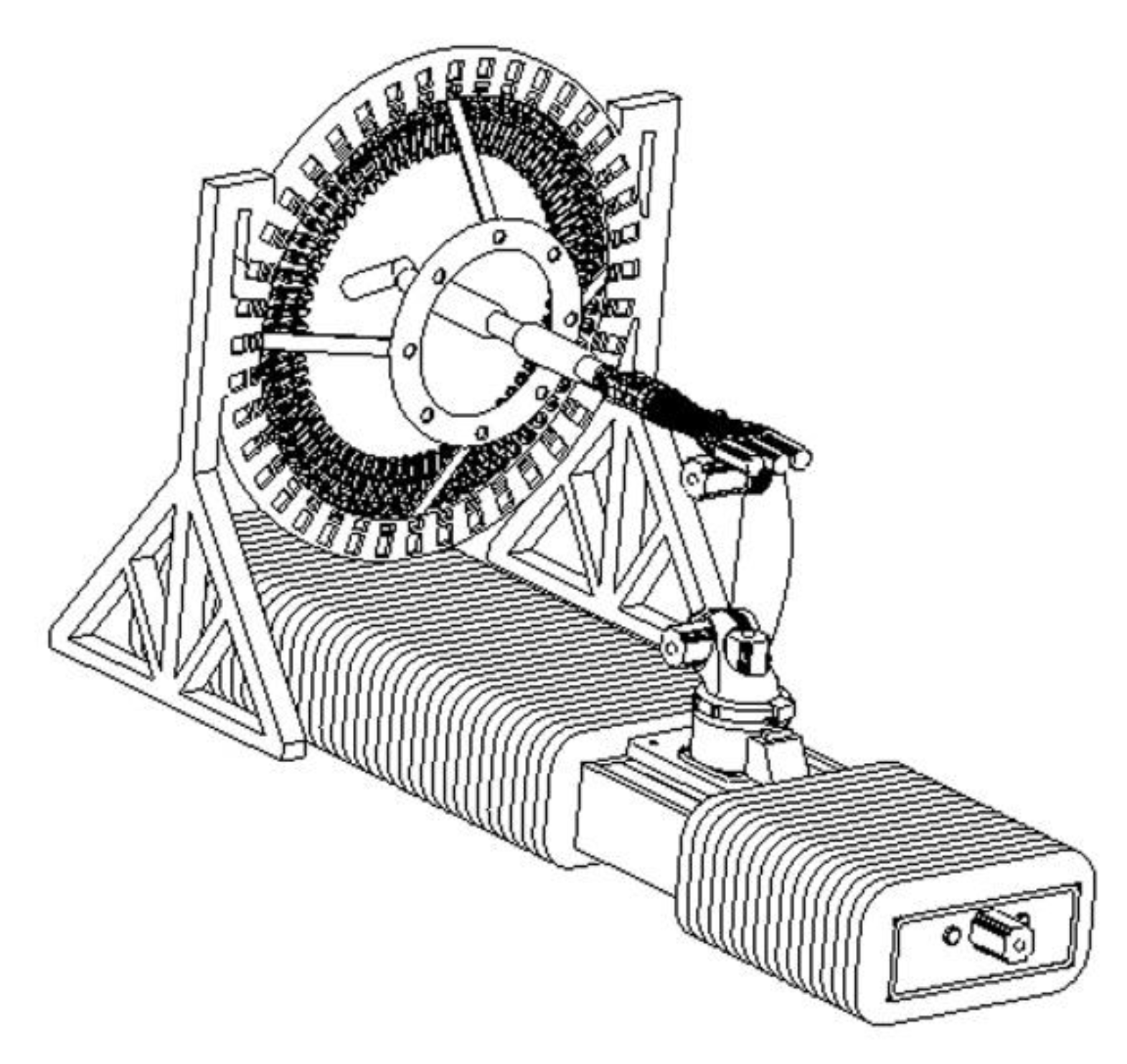
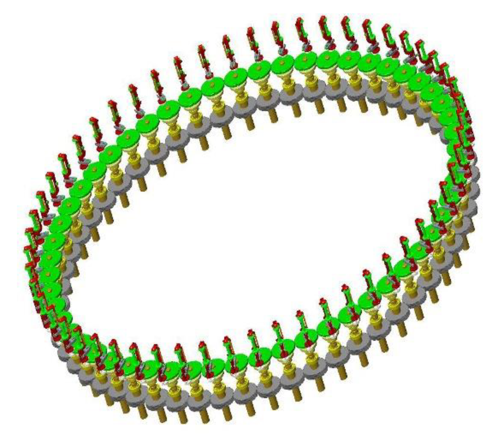
1. Introduction
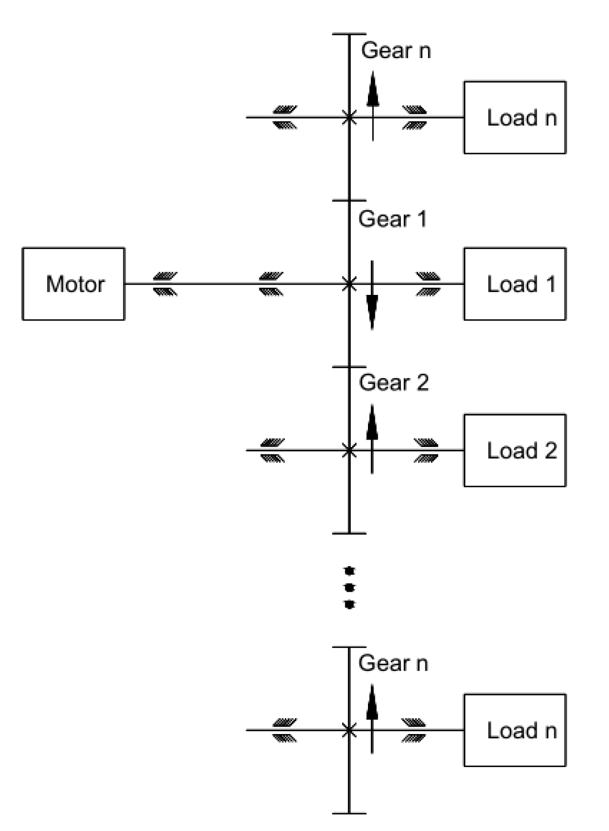
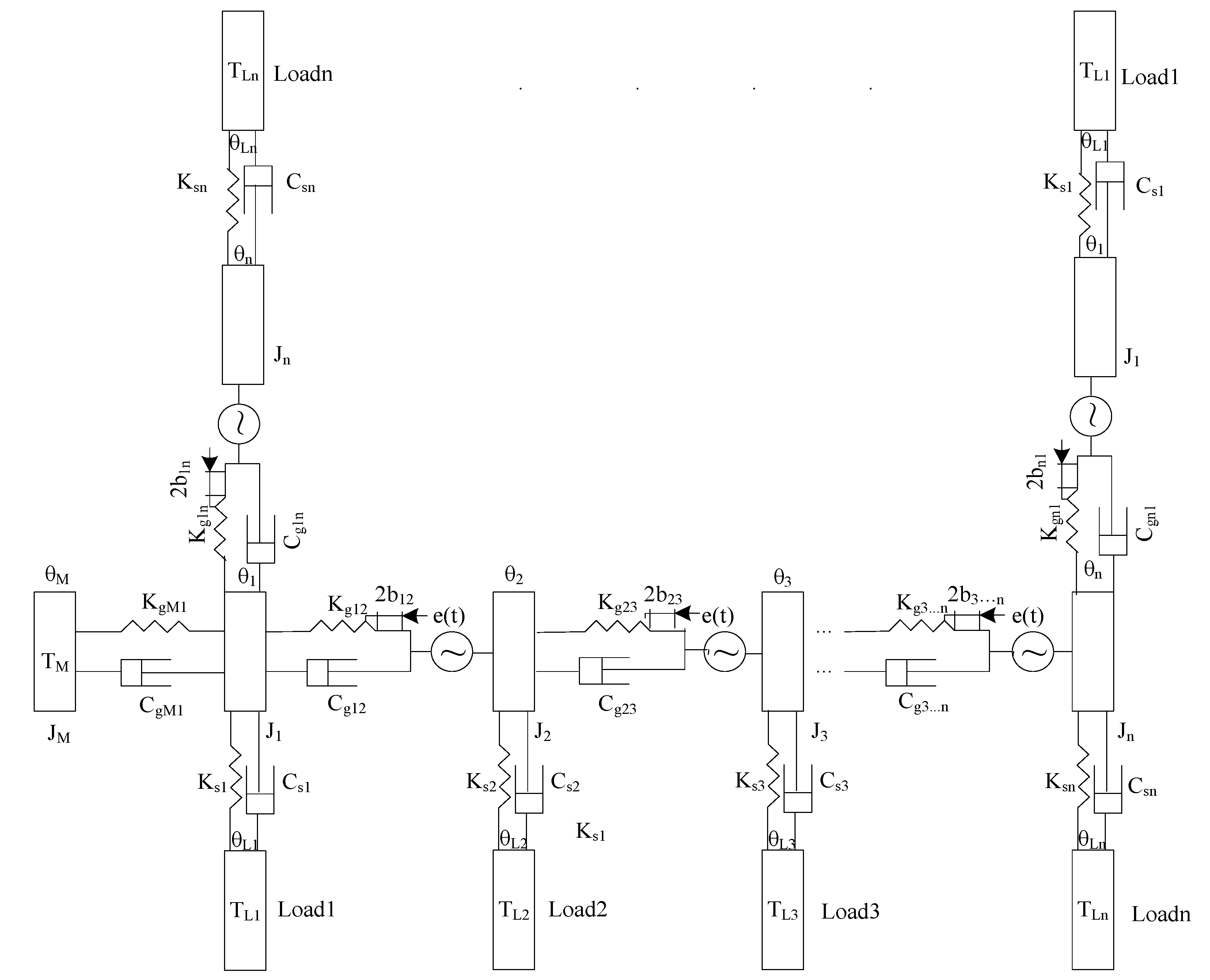
2. Torsional Vibration Model of n-Elements Closed-loop Gear Transmission System
2.1. Torsional Vibration Model of Gear System
2.2. Non-linear Differential Equations of Torsional Vibration
3. The Simulation Analysis of MATLAB
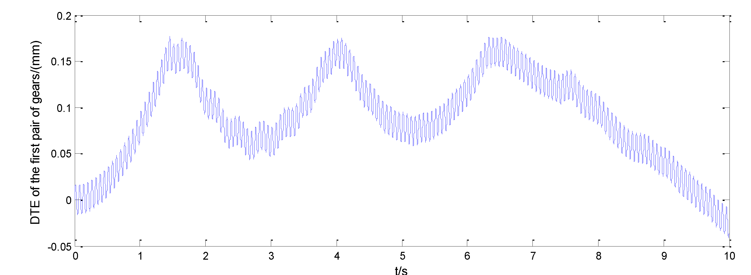
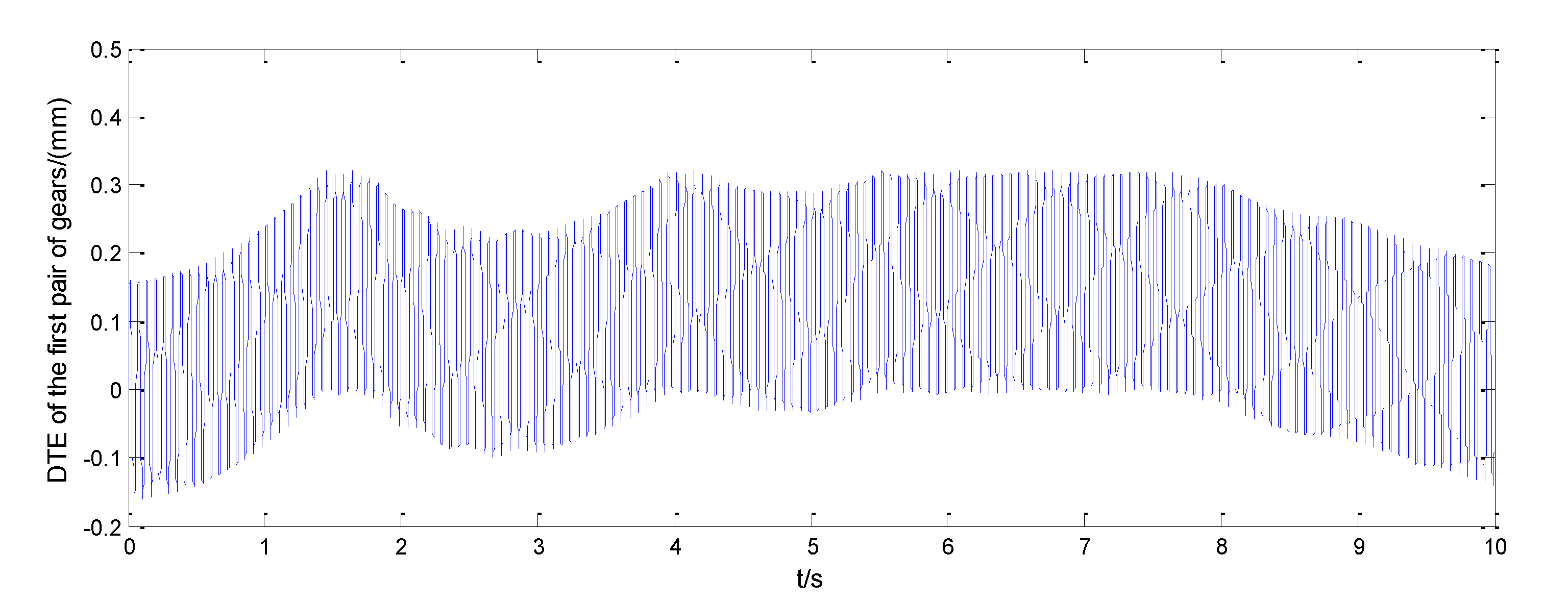
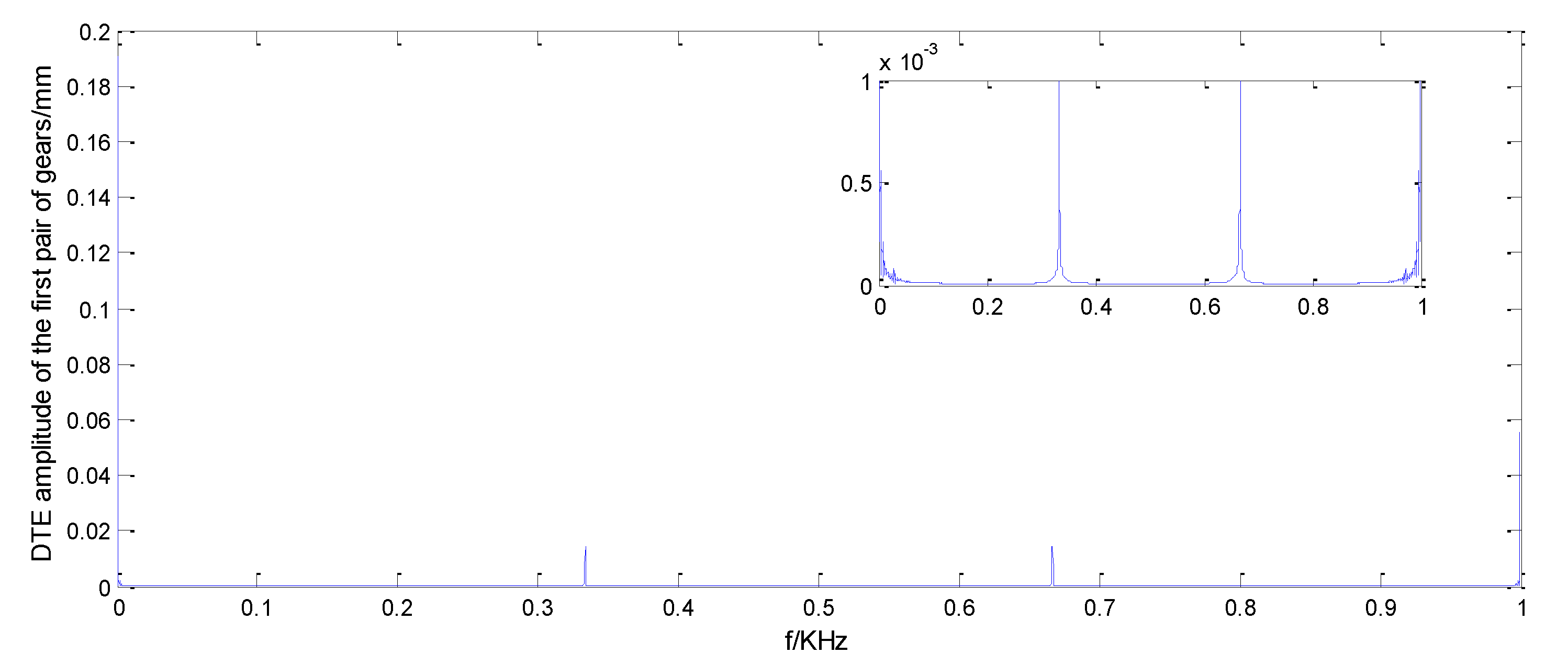
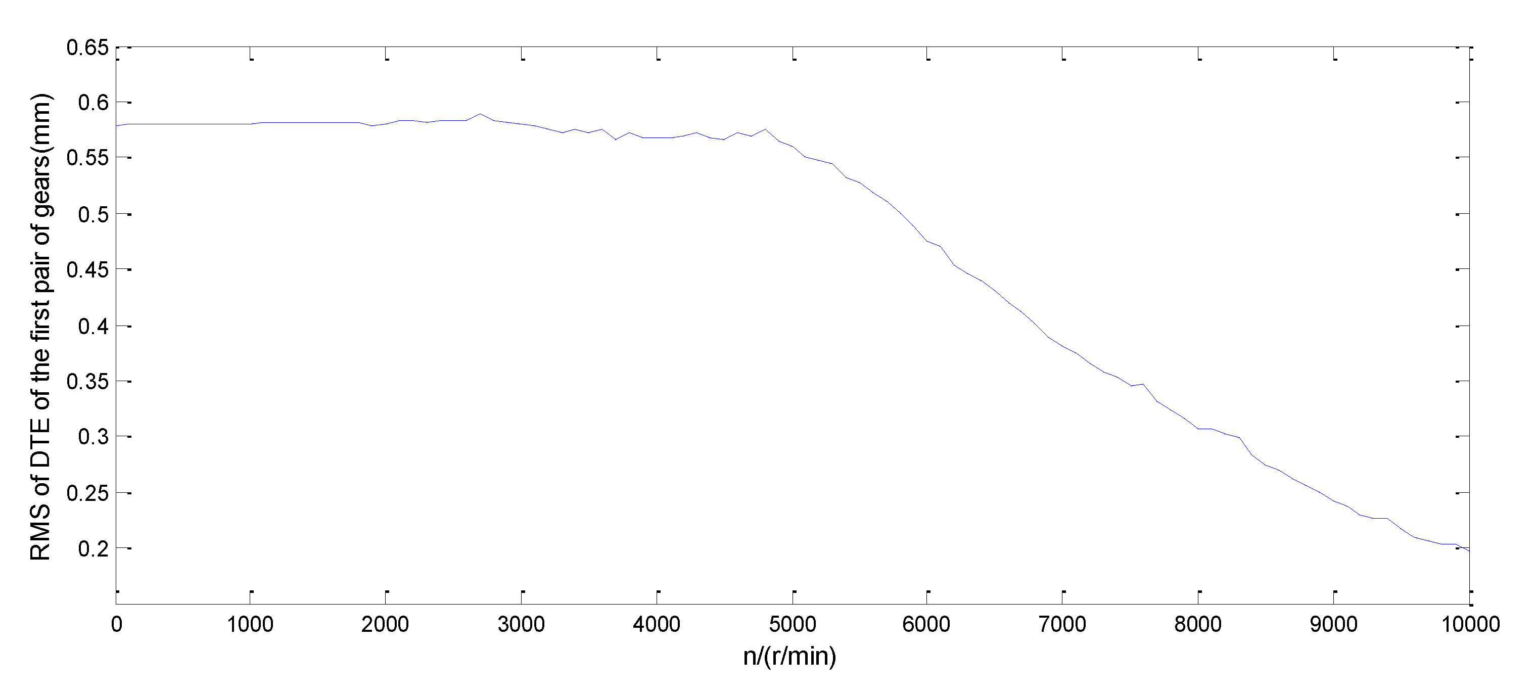
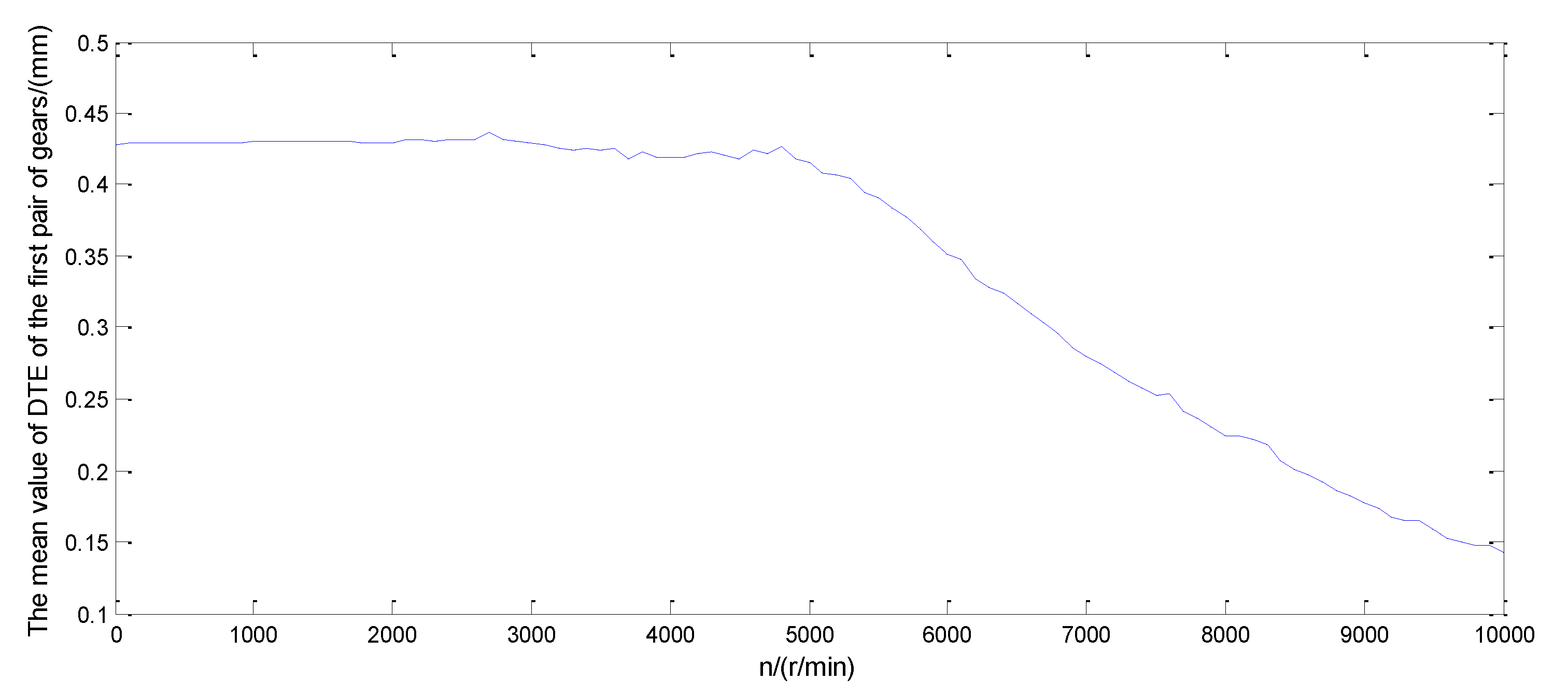
3.1. The Analysis about Dynamic Transmission Error of the First Pair of Gears
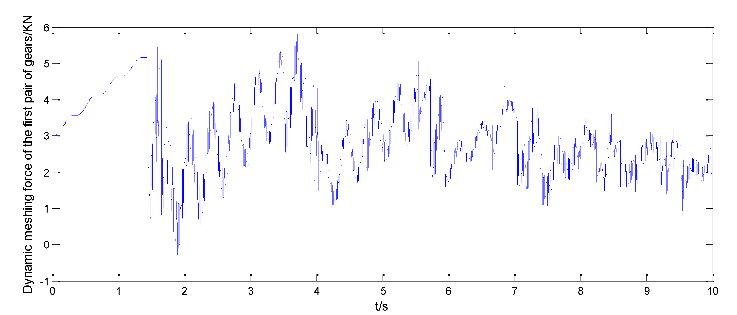
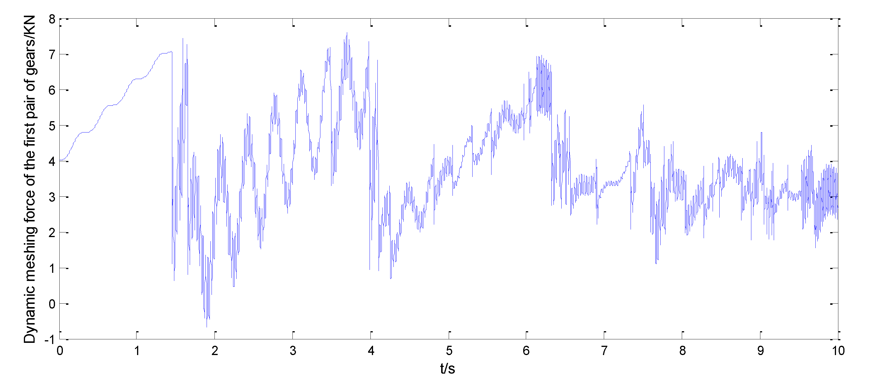
3.2. The Analysis about Dynamic Meshing Force of the First Pair of Gears
4. Conclusions
Author Contributions
Funding
Acknowledgments
Conflicts of Interest
References
- Megel, M.; Kumosa, L.; Ely, T.; Armentrout, D.; Kumosa, M. Initiation of stress-corrosion cracking in unidirectional glass/polymer composite materials. Compos. Sci. Technol. 2001, 61, 231–246. [Google Scholar] [CrossRef]
- Hull, D.; Kumosa, M.; Price, J.N. Stress corrosion of aligned glass fiber-polyester composite material. Mater. Sci. Tech. Lond. 1985, 1, 177–182. [Google Scholar] [CrossRef]
- Noble, B.; Harris, S.J.; Owen, M.J. Stress corrosion cracking of GRP pultruded rods in acid environments. J. Mater. Sci. 1983, 18, 1244–1254. [Google Scholar] [CrossRef]
- Ma, G.; Branscomb, D.; Beale, D.G. Modeling of the tensioning system on a braiding machine carrier. Mech. Mach. Theory 2012, 47, 46–61. [Google Scholar] [CrossRef]
- Zhou, H.; Zhang, W.; Liu, T.; Gu, B.; Sun, B. Finite element analyses on transverse impact behaviors of 3-D circular braided composite tubes with different braiding angles. Compos. Part A Appl. Sci. Manuf. 2015, 79, 52–62. [Google Scholar] [CrossRef]
- Guyader, G.; Gabor, A.; Hamelin, P. Analysis of 2D and three-dimensional circular braiding processes: Modeling the interaction between the process parameters and the pre-form architecture. Mech. Mach. Theory 2013, 69, 90–104. [Google Scholar] [CrossRef]
- Van Ravenhorst, J.; Akkerman, R. Circular braiding take-up speed generation using inverse kinematics. Compos. Part A Appl. Sci. Manuf. 2014, 64, 147–158. [Google Scholar] [CrossRef]
- Van Ravenhorst, J.; Akkerman, R. A yarn interaction model for circular braiding. Compos. Part A Appl. Sci. Manuf. 2016, 81, 254–263. [Google Scholar] [CrossRef]
- Na, W.; Ahn, H.; Jeon, S.; Lee, J.S.; Kang, H.; Yu, W. Prediction of the braid pattern on arbitrary-shaped mandrels us-ing the minimum path condition. Compos. Sci. Technol. 2014, 91, 30–37. [Google Scholar] [CrossRef]
- Hans, T.; Cichosz, J.; Brand, M.; Hinterhölzl, R. Finite element simulation of the braiding process for arbitrary mandrel shapes. Compos. Part A Appl. Sci. Manuf. 2015, 77, 124–132. [Google Scholar] [CrossRef]
- Kyosev, Y. Braiding Technology for Textiles; Woodhead Publishing: MÖnchengladbach, Germany, 2015. [Google Scholar]
- Philippe, M.; Jonathan, L.; Lebel, L.L. Automated braiding of a complex aircraft fuselage fr-ame using a non-circular braiding model. Compos. Part A Appl. Sci. 2017, 102, 48–63. [Google Scholar]
- Heieck, F.; Hermann, F.; Middendorf, P.; Schladitz, K. Influence of the cover factor of 2D biaxial and triaxial braided carbon composites on their in-plane mechanical properties. Compos. Struct. 2017, 163, 114–122. [Google Scholar] [CrossRef]
- Wehrkamp-Richter, T.; Hinterhölzl, R.; Pinho, S.T. Damage and failure of triaxial braided composites under multi-axial stress states. Compos. Sci. Technol. 2017, 150, 32–44. [Google Scholar] [CrossRef]
- Swery, E.; Hans, T.; Bultez, M.; Wijaya, W.; Kelly, P.; Hinterhölzl, R.; Bickerton, S. Complete simulation process chain for the manufacturing of braided composite parts. Compos. Part A Appl. Sci. Manuf. 2017, 102, 378–390. [Google Scholar] [CrossRef]
- Kahraman, A.; Singh, R. Non-linear dynamics of a spur gear pair. J. Sound Vib. 1990, 142, 49–75. [Google Scholar] [CrossRef]
- Kahraman, A.; Singh, R. Interactions between time-varying mesh stiffness and clearance non-linearities in a geared system. J. Sound Vib. 1991, 146, 135–156. [Google Scholar] [CrossRef]
- He, S.; Rook, T.; Singh, R. Construction of semianalytical solutions to spur gear dyna mics given periodic mesh stiffness and sliding friction functions. J. Mech. Design 2008, 130, 1226011–1226019. [Google Scholar] [CrossRef]
- Liu, G.; Parker Robert, G. Dynamic modeling and analysis of tooth profile modification for multi-mesh gear vibration. J. Mech. Design 2008, 130, 1214021–12140213. [Google Scholar] [CrossRef]
- Cui, Y.; Liu, Z.; Wang, Y.; Ye, J. Nonlinear Dynamic of a Geared Rotor System with Nonlinear Oil Film Force and Nonlinear Mesh Force. J. Vib. Acoust. 2012, 134, 041001. [Google Scholar] [CrossRef]
- Baguet, S.; Jacquenot, G. Nonlinear couplings in a gear-shaft-bearing system. Mech. Mach. Theory 2010, 45, 1777–1796. [Google Scholar] [CrossRef]
- Li, S.; Kahraman, A. A tribo-dynamic model of a spur gear pair. J. Sound Vib. 2013, 332, 4963–4978. [Google Scholar] [CrossRef]
- Wei, J.; Sun, Q.; Sun, W.; Qin, D.; Zhu, C.; Zhu, W.; Guo, A. Dynamic analysis and effects of nonlinear factors of a gear transmission system for high speed locomotive. J. Vib. Shock 2012, 31, 38–43, 50. [Google Scholar]
- Zhang, H.; Wang, R.; Chen, Z.; Wei, C.; Zhao, Y.; You, B.; School of Astronautics, Harbin Institute of Technology. Nonlinear dynamic analysis of a gear-rotor system with coupled multi-clearance. J. Vib. Shock 2015, 34, 144–150, 192. [Google Scholar]
- Li, R.; Wang, J. Gear System Dynamics-Vibration, Shock & Nois; Science Press: Beijing, China, 1997; pp. 158–163. [Google Scholar]
- Zhang, Y. Mechanical vibration; Tsinghua University Press: Beijing, China, 2007; pp. 78–100. [Google Scholar]
- Al-Shyyab, A.; Kahraman, A. Non-linear dynamic analysis of a multi-mesh gear train using multi-term harmonic balance method: Period-one motions. J. Sound Vib. 2005, 284, 151–172. [Google Scholar] [CrossRef]
- Yi, Y.; Huang, K.; Xiong, Y.; Sang, M. Non-linear dynamic modelling and analysis for a spur gear system with time-varying pressure angle and gear backlash. Mech. Syst. Signal Process. 2019, 132, 18–34. [Google Scholar] [CrossRef]
- Özgüven, H.N.; Houser, D. Mathematical models used in gear dynamics—A review. J. Sound Vib. 1988, 121, 383–411. [Google Scholar] [CrossRef]
- Shin, D.; Palazzolo, A. Nonlinear analysis of a geared rotor system supported by fluid film journal bearings. J. Sound Vib. 2020, 475, 115269. [Google Scholar] [CrossRef]
- Pan, W.; Li, X.; Wang, L.; Yang, Z. Non-linear response analysis of gear-shaft-bearing system considering tooth contact temperature and random excitations. Appl. Math. Model 2019, 68, 113–136. [Google Scholar] [CrossRef]
- Hasnijeh, S.G.; Poursina, M.; Leira, B.J.; Karimpour, H.; Chai, W. Stochastic dynamics of a nonlinear time-varying spur gear model using an adaptive time-stepping path integration method. J. Sound Vib. 2019, 447, 170–185. [Google Scholar] [CrossRef]
- Wang, Y.; Zhang, W.J. Stochastic vibration model of gear transmission systems con-sidering speed-dependent random errors. Nonlinear Dyn. 1998, 17, 187–203. [Google Scholar] [CrossRef]
- Naess, A.; Kolnes, F.E.; Mo, E. Stochastic spur gear dynamics by numerical path in-tegration. J. Sound. Vib. 2007, 302, 936–950. [Google Scholar] [CrossRef]
- Fang, Y.; Liang, X.; Zuo, M.J. Effects of friction and stochastic load on transient cha-racteristics of a spur gear pair. Nonlinear Dyn. 2018, 93, 599–609. [Google Scholar] [CrossRef]


| Gear 1 | Gear 2 | Gear 3 | |
|---|---|---|---|
| Modulus/mm | 4 | 4 | 4 |
| Tooth number z | 30 | 30 | 30 |
| Tooth width B/mm | 10 | 10 | 10 |
| Pressure angle /(°) | 20 | 20 | 20 |
| Modification coefficient | 0.5047 | 0.5047 | 0.5047 |
Publisher’s Note: MDPI stays neutral with regard to jurisdictional claims in published maps and institutional affiliations. |
© 2020 by the authors. Licensee MDPI, Basel, Switzerland. This article is an open access article distributed under the terms and conditions of the Creative Commons Attribution (CC BY) license (http://creativecommons.org/licenses/by/4.0/).
Share and Cite
Yao, L.; Meng, Z.; Bu, J.; Sun, Y. Non-Linear Dynamic Feature Analysis of a Multiple-Stage Closed-Loop Gear Transmission System for 3D Circular Braiding Machine. Symmetry 2020, 12, 1788. https://doi.org/10.3390/sym12111788
Yao L, Meng Z, Bu J, Sun Y. Non-Linear Dynamic Feature Analysis of a Multiple-Stage Closed-Loop Gear Transmission System for 3D Circular Braiding Machine. Symmetry. 2020; 12(11):1788. https://doi.org/10.3390/sym12111788
Chicago/Turabian StyleYao, Lingling, Zhuo Meng, Jianqiu Bu, and Yize Sun. 2020. "Non-Linear Dynamic Feature Analysis of a Multiple-Stage Closed-Loop Gear Transmission System for 3D Circular Braiding Machine" Symmetry 12, no. 11: 1788. https://doi.org/10.3390/sym12111788
APA StyleYao, L., Meng, Z., Bu, J., & Sun, Y. (2020). Non-Linear Dynamic Feature Analysis of a Multiple-Stage Closed-Loop Gear Transmission System for 3D Circular Braiding Machine. Symmetry, 12(11), 1788. https://doi.org/10.3390/sym12111788