Article

A New Approach in Analytical Dynamics of Mechanical Systems

by
Iuliu Negrean
1,*,
Adina-Veronica Crișan
1,* and
Sorin Vlase
2,*
1
Department of Mechanical Systems Engineering, Faculty of Machine Building, Technical University of Cluj–Napoca, 400641 Cluj–Napoca, Romania
2
Department of Mechanical Engineering, Faculty of Mechanical Engineering, Transilvania University of Brașov, 500036 Brașov, Romania
*
Authors to whom correspondence should be addressed.
Symmetry 2020, 12(1), 95; https://doi.org/10.3390/sym12010095
Submission received: 8 October 2019 / Revised: 19 December 2019 / Accepted: 26 December 2019 / Published: 3 January 2020
(This article belongs to the Special Issue Conservation Laws and Symmetries of Differential Equations)

Abstract

:
This paper presents a new approach to the advanced dynamics of mechanical systems. It is known that in the movements corresponding to some mechanical systems (e.g., robots), accelerations of higher order are developed. Higher-order accelerations are an integral part of higher-order acceleration energies. Unlike other research papers devoted to these advanced notions, the main purpose of the paper is to present, in a matrix form, the defining expressions for the acceleration energies of a higher order. Following the differential principle in generalized form (a generalization of the Lagrange–D’Alembert principle), the equations of the dynamics of fast-moving systems include, instead of kinetic energies, the acceleration energies of higher-order. To establish the equations which characterize both the energies of accelerations and the advanced dynamics, the following input parameters are considered: matrix exponentials and higher-order differential matrices. An application of a 5 d.o.f robot structure is presented in the final part of the paper. This is used to illustrate the validity of the presented mathematical formulations.

1. Introduction

Mechanical systems characterized by ultra-fast movements also include serial structures of robots. According to Eager, Pendrill and Visser [1,2] and to the authors’ previous research [3,4], the fast movements occur when the linear acceleration is according to the following condition: a 2 g , where g is the acceleration gravity. As a result, the fast movements of mechanical systems are characterized by a time variation law for the acceleration, which can be plotted in the form of a higher-order parabola. Therefore, these observations lead to the conclusion that in mechanical systems subjected to fast movements, higher-order accelerations, also known in the scientific literature as jerk, snap, crackle, and pop [5], are occurring. The notion of second-order and higher-order accelerations is of major importance in the field of theoretical mechanics, but significant developments in other fields of science were also noted: numerical analysis [6,7], control [8], differential equations [8], astronomy, astrophysics, and space physics [9,10,11,12,13], medicine [14,15], meteorology [16] and many more. The main purpose of this paper was not to conduct an exclusive kinematic study on higher-order accelerations. According to [3,4], the higher-order accelerations become central functions in the expressions of the so-called higher-order acceleration energies. Appell determined the expression for the first order acceleration energy in the case of material particles, and for discrete material particle systems [17,18]. Recently, an impressive increase in the use of robots in manufacturing processes has been recorded, with great achievements in the field of control or of the speeds and forces developed during the work process. These developments have spurred the research in the field. In the case of robotic systems, which are generally operating at high working speeds, their accelerations become extremely important. For this reason, the Gibbs–Appell formalism is useful in solving a large variety of problems. In the scientific literature, there is a large number of papers that consider this formalism in the study of the dynamical system. In the following, we will mention some important achievements in this area of study. For example, in [19], a formulation for determining the rigid body dynamics by considering the quasi-velocities is proposed. So, based on the Gibbs–Appell formalism, the equations of motion with holonomic and nonholonomic constraints, were obtained. Thus, based on this method, it is possible to eliminate the Lagrange multipliers classically and, therefore, to reduce the number of equations. In [20], a nonlinear dynamic analysis performed on a flexible-link manipulator is presented. Here, to obtain the motion equations for the N-link robot, the Gibbs–Appell recursive formulation is applied. For this purpose, the case of a two-link flexible robot is considered. By numerical integration of the equations, the results are obtained. The experimental procedure validates the results. Many papers study this type of mechanical system consisting of a flexible manipulator by using the Gibbs–Appell (GA) classic formalism. The paper [21] presents an application involving a mechanical system consisting of an N-flexible-link manipulator. The recursive (GA) formulation, applied in this case, allows solving the equations without using the Lagrange multipliers. Therefore, the heavy and simultaneous computations for eliminating the constraints applied to the platform and arms are circumvented. Finally, the forward dynamics solution in the case of two flexible and single-arm manipulator with revolute-prismatic joints is obtained. These motion equations are essential in the control of sensitive bodies. In [22] a systematic method to study the dynamic behavior of multi-rigid links is presented. This type of system is defined based on two different mathematical models: a classic set of highly coupled differential equations and a set of algebraic equations for expressing the constraints. The Lagrangian formulation implies an excessive number of derivatives in the governing motion equations, and hence, the use of the Gibbs-Appell recursive formulation seems to be an adequate choice. The recursive Gibbs-Appell formulation has been used in [23] to obtain the final motion equations. The main advantage of this formulation is that there is no need to eliminate Lagrange’s multipliers. The main purpose of the matrix formulations in the study of the dynamics of the systems with linkages consists in the reduction of the computational effort, significant for this type of application. Some studies presenting different formulations based on the Gibbs–Appell equation conclude that this involves, less computational operations [24,25,26]. In the present paper, the equations of advanced dynamics corresponding to the serial robot structures are determined. According to the principles from advanced mechanics, serial robots are considered holonomic mechanical systems. As a result, in the case of these mechanical structures, the Gibbs-Appell starting equations will have a particular case of application. According to [27,28], the dynamic study of mechanical systems is based on the principle of D’Alemebert and on Lagrange’s equations of the second kind, specific to conservative and non-conservative mechanical systems. The paper proposes an alternative to the principles mentioned above, by using the Gibbs–Appell formalism as starting equations. Thus, the main objectives consist in determining the expressions for the acceleration energies of higher-order and in including them in the equations of advanced dynamics. To understand the expressions corresponding to acceleration energies and the equations of advanced dynamics, in the first part of the paper some important issues regarding the input parameters are highlighted: homogeneous transformations, matrix exponentials, and differential matrices corresponding to the advanced kinematics. In the second part, the defining expressions for the acceleration energies of the first, second and third-order, in a matrix form, will be determined. Within these expressions, the occurrence of the first, second and third-order dynamics matrices is noted. These include the differential matrices from advanced kinematics. The advanced dynamics equations are developed in the third part of the paper. The analysis of these expressions highlight the existence of higher-order generalized forces, of which, the generalized inertia forces are essential. Considering the differential principle, in a generalized form, the expressions for the generalized inertia forces of higher orders will be presented. The latter include the acceleration energies of higher-order, corresponding to the fast movements, specific to robot serial structures. In the final part of the paper, an experimental application focused on the analysis of the motion performed by a 5 d.o.f Fanuc robot is presented.

2. Matrices of the Homogenous Transformations

As stated in a previous paper [4], to perform the dynamic analysis of mechanical systems, some basic mechanical models are used: the material point and rigid body respectively. They are both characterized by three and six degrees of freedom. To describe the position of a point or a rigid body, either three or six independent coordinates must be defined. Usually, the position is given in a Cartesian reference system, which makes it convenient to express it as a vector, also known as radius vector. For defining the position and the orientation of a rigid body, an additional frame is attached, which will move along with the body. This frame will define the position of the body, by considering the position vector of an arbitrary point of the body (identical with the origin of the frame attached to the body) and additionally a 3 × 3 matrix, called the orientation matrix. In Newtonian mechanics, the displacement of a rigid body from an initial position to a final one results by the superposition of two motions: a resultant translation and a resultant rotation. So, if the position vector of a point relative to the moving frame (attached to the body) is known, and the position vector of this point relative to the fixed frame is to be determined, two mathematical operations are applied: the multiplication of orientation matrices and the addition of vectors. In case the homogeneous transformations are applied, the calculus is noticeably simplified.
Homogeneous transformations are defined using (4 × 4) matrices, which include the translation (position) of a frame as well as its rotation (orientation).
The advantages given by this representation makes it very popular in robotics, an interdisciplinary branch of science and engineering, where multibody systems are commonly studied. In the classical modeling, the positions of the links relative to a global, fixed frame are defined. To describe the motion of a mechanical system with ( n ) links, it is compulsory to specify the number of (6 × n) parameters also called the absolute coordinates (Figure 1).
The joint coordinates define the motion of any robot link relative to the previous link from a kinematic chain (Figure 1). In this way, by using fewer parameters, the positions of the system’s adjoining links are described. This section provides a basic introduction in defining the positions and orientations of a rigid body, as well as the transformations applied to the position vectors. The implementation of homogeneous transformations in defining the geometry of multibody systems is discussed. The position and orientation of a moving frame, denoted O x y z { S } , relative to another frame, for example, a fixed frame { 0 } , can be comprised in a matrix form, according to [29,30] by applying the homogeneous transformations, in a classical form or by using the matrix exponentials:
[ T ] S 0 ( 4 × 4 ) ( t ) = [ [ R ] S 0 ( t ) p ¯ ( t ) 0 0 0 1 ] = [ { χ = { u ;   v ;   w } } exp [ χ ¯ × δ χ ] p ¯ ( t ) 0           0        0   1 ] ,
p ¯ ( t ) = { χ = { u ;   v ;   w } } { { χ = { u ;   v ;   w } } exp [ χ ¯ × δ χ ] } b ¯ χ + { { χ = { u ;   v ;   w } } exp [ χ ¯ × δ χ ] } p ¯ ( 0 ) Δ   p ,   where   Δ   p = { { 0 ;   p ¯ = r ¯ 0 } ; { 1 ;   p ¯ = r ¯ M } } ,
b ¯ χ = [ χ ¯ ( 0 ) χ ¯ ( 0 ) T ( δ χ s δ χ ) + I 3 s δ χ + ( χ ¯ ( 0 ) × ) ( 1 c δ χ ) ] [ p ¯ ( 0 ) × χ ¯ ( 0 ) Δ   χ + ( 1 Δ χ ) χ ¯ ( 0 ) ] .
The position of the mobile system { S } relative to a fixed system { 0 } is defined by (2), while expression (3) is useful to represent a vector by means of homogenous coordinates as a function of screw parameters. The homogenous coordinates from expression (3) are written as:
χ ¯ ( 0 ) = { u ¯ 0 ;   v ¯ 0 ;   w ¯ 0 }   w h e r e   u ¯ 0 = { i ¯ 0 ;   j ¯ 0 ;   k ¯ 0 } ;   v ¯ 0 = { j ¯ 0 ;   k ¯ 0 ;   i ¯ 0 } u ¯ 0 ;   w ¯ 0 = { k ¯ 0 ;   i ¯ 0 ;   j ¯ 0 } v ¯ 0 ,
a n d   p ¯ ( 0 ) × χ ¯ ( 0 ) Δ   χ + ( 1 Δ χ ) χ ¯ ( 0 ) ,
where χ ¯ ( 0 ) represents the unit vector of the driving axis and the symbols δ χ and Δ χ included in the expression (3) are defined according to [4], as presented below:
δ χ = { α χ ;   β χ ;   γ χ } ;   cos δ χ = c δ χ ;   sin δ χ = s δ χ .
According to [4], the generalized expression that characterizes the three simple rotation matrices, components of the s 0 [ R ] generalized rotation matrix included in (1), is written as:
R ( χ ¯ ;   δ χ ) = { R ( x ¯ ;   α x ) ;   R ( y ¯ ;   β y ) ;   R ( z ¯ ;   γ z ) } = [ c ( δ χ Δ   y z ) s ( δ χ Δ   z ) s ( δ χ Δ   y ) s ( δ χ Δ   z ) c ( δ χ Δ   z x ) s ( δ χ Δ   x ) s ( δ χ Δ   y ) s ( δ χ Δ   x ) c ( δ χ Δ   x y ) ]
Δ   u { χ = u } = { Δ   x ;   Δ   y ;   Δ   z } = 1 Δ   v w {   χ = { v ;   w }   } , w h e r e   χ = { u ;   v ;   w } ,   a n d   u = { x ;   y ;   z } ;   v = { y ;   z ;   x } u ;   w = { z ;   x ;   y } v , Δ   u v {   χ = { u ;   v }   } = { Δ   y z ;   Δ   z x ;   Δ   x y } = { 1 , i f   δ χ = { ( β y ;   γ z ) ,   ( γ z ;   α x ) ,   ( α x ;   β y ) }   0 , i f   δ χ = { α x ,   β y ,   γ z } } .
The conclusions and the expressions of definition, from this section, are applied in the advanced kinematics and dynamics of mechanical systems. In the kinematic study, the generalized coordinates which define the motion of each driving joint from the robot’s mechanical structure becomes a function of time. Thus, the time derivative, as well as the partial derivatives, can be applied. The column vector of the generalized coordinates θ ¯ ( t ) , for a certain configuration different from the initial (zero) configuration θ ¯ ( 0 ) , has the following mathematical expression:
θ ¯ θ ¯ ( 0 )   ;   θ ¯ ( t ) = [ q i ( t ) ;   i = 1 n ] T .
{ θ ¯ ( t ) ;   θ ¯ ˙ ( t ) ;   θ ¯ ¨ ( t ) ; ; θ ¯ ( m ) ( t ) } = { q i ( t ) ;   q ˙ i ( t ) ;   q ¨ i ( t ) ; ;   q i ( m ) ( t ) i = 1 n ,   m 1 } .
where q i ( t ) is the generalized coordinate from every driving axis, and ( m ) represents the time deriving order. The generalized variables of higher order (9) can be developed, according to [4], and considering the current and fast motions. The main objective of the Section 3 consists in determining the advanced kinematic parameters from each kinetic ensemble. Unlike the classical approaches [31,32,33], few formulations based on time derivatives of the locating matrices is developed. For this purpose, in Figure 1 a sequence of two kinetic ensembles ( i 1 ) ( i ) , from the mechanical structure of a serial robot, subjected to kinematical study is considered. According to [4], the matrices of the homogenous transformations are defined with the following expressions:
[ T ] i 0 ( t ) = [ T ] i 0 ( t )   [ T ] i i 1 ( t ) = [ [ R ] i 0 ( t ) p ¯ i ( t ) 0   0   0 1 ] = [ [ R ] i 1 0 ( t ) [ R ] i i 1 p ¯ i 1 + p ¯ i i 1 0      0      0 1 ] .
Expression (10) defines the position and orientation of the moving frame { i } , attached in the mass center of every joint relative to { 0 } (a fixed frame attached to the robot base). The components with the same meaning are written below:
[ T ] i 1 0 ( t ) = [ [ R ] i 1 0 ( t ) p ¯ i 1 ( t ) 0   0   0 1 ] ,   [ T ] i i 1 ( t ) = [ [ R ] i i 1 p ¯ i 1 i i 1 0   0   0 1 ] .
The matrix components from Equations (10) and (11) are defined according to:
[ R ] i i 1 = R i i 1 R ( k ¯ i ; q i ( t ) Δ   i ) ,   [ R ] i 0 ( t ) = [ R ] i 1 0 ( t )   [ R ] i i 1 ,
p ¯ i 1 i i 1 = p ¯ i 1 i i 1 ( 0 ) + ( 1 Δ   i ) q i ( t )   k ¯ i 1 i ,   p ¯ i ( t ) = p ¯ i 1 ( t ) + [ R ] i 1 0   p ¯ i 1 i i 1 ,   Δ   i = { [ 1 ,   i = R ] ;   [ 0 ,   i = T ] } .
The symbols presented in Equations (1)–(13) have the following meaning:
  • [ T ] S 0 ( 4 × 4 ) ( t ) is the homogenous transformation between the system { S } and the fixed system { 0 } ;
  • [ T ] i 1 0 ( t ) is the homogenous transformation between the mobile system { i } and fixed system { 0 } ;
  • [ R ] i i 1 is the orientation matrix between the adjoining mobile systems { i 1 } and { i } ;
  • [ R ] i 0 defines the orientation matrix between the mobile system { i } and fixed system { 0 } ;
  • p ¯ i 1 i i 1 defines the relative position between systems { i 1 } { i } and p ¯ i ( t ) the absolute position of the systems { 0 } { i } .

3. Advanced Kinematics Notions

In this section, some important research regarding the matrix exponentials, Jacobian matrix, and the equations of advanced kinematics are presented. In all studies developed by the authors, the Jacobian matrix represents the transfer matrix of linear and angular velocities. In the scientific literature, the Jacobian matrix is known as the matrix of partial derivatives applied to the position and orientation functions for the last element in the kinematic chain of the mechanical system. The expressions for the differential matrices are also developed. They have an essential role in establishing the acceleration energies of higher-orders and the equations of advanced dynamics for any mechanical structure subjected to fast motions.

3.1. Matrix Exponentials in Advanced Kinematics

The homogenous transformations, which were previously defined, in a classical form, are further developed in exponential form. As a result, the homogenous transformations between the systems { 0 } { n } and { 0 } { n + 1 } as well, where { n + 1 } { S } , are established according to [29,30]:
[ T ] n 0 = T n 0 = i = 1 n T i i 1 ( q i ) = ( j = 1 i 1 δ j j 1 ) 1 ( j = 1 i T j j 1 ( 0 ) ) exp ( U i q i ) E j j 1 ,
w h e r e   E j j 1 = ( j = 1 i T j j 1 ( 0 ) ) 1 ( j = 1 i T j j 1 ( 0 ) )   a n d   δ j j 1 = {   {   T j j 1 ( 0 ) ;   i 2   }   ;   { I 4 ;   i = 1   }   } , and   U i = τ i [ { k ¯ ( i )   i 1 i ×   } Δ i   k ¯ ( i )   i 1 i ( 1 Δ i ) 0   0   0 0 ] ,   τ i = ± 1 ,
T x 0 = i = 1 x T i i 1 = [ R x 0 p ¯ 0   0   0 1 ] = { i = 1 n exp [ A i q i ] } T x 0 ( 0 ) ,   w h e r e   x = { n   ;   n + 1 S } .
The symbol U i included in Equation (14) defines the Uicker differential operator.
  • k ¯ k ( i ) ( 0 ) is the unit vector, in the initial configuration of the driving axis corresponding to the generalized coordinate q k ( i ) ;
  • Δ k ( i ) = 1 when q k ( i ) corresponds to an angular coordinate, otherwise Δ k ( i ) = 0 .
In the expression (16), the rotation submatrix R x 0 and the position vector p ¯ , are defined as:
R x 0 = { i = 1 n exp { k ¯ i ( 0 ) × }   q i Δ   i }     R x 0 ( 0 ) ,
p ¯ = i = 1 n { j = 0 i 1 exp { k ¯ j ( 0 ) × }   q j Δ j } b ¯ i + { i = 1 n exp { k ¯ i ( 0 ) × }   q i Δ   i } p ¯ ( 0 ) δ x ,   δ x = { { 0 ;   x = n } ;   { 1 ;   x = n + 1 } } .
Also, within the matrix defined with (16), the exponent ( 0 ) characterizes the initial configuration of the mechanical system, and the symbol A i represents a ( 4 × 4 ) matrix whose components are given by the homogenous coordinates or screw parameters k ¯ i ( 0 ) and v ¯ i ( 0 ) :
A i = [ { k ¯ i ( 0 )   × }   Δ   i   v ¯ i ( 0 ) 0      0      0 0 ] = [ { k ¯ i ( 0 )   × }   Δ   i { p ¯ i ( 0 )   ×   }   k ¯ i ( 0 ) Δ   i + ( 1 Δ   i )   k ¯ i ( 0 ) 0      0      0 0 ] .
In the study of advanced kinematics and dynamics, the partial derivatives applied to the homogeneous transformations expressed by the matrix exponentials play an essential role.
  {   T n 0 }   q i   = { j = 0 i 1 exp [ A j q j ] }   A i   { k = i n exp [ A k q k ] }   T n ( 0 ) = [ A n i ( R ) A n i ( p ¯ ) 0   0   0 0 ] .
In establishing the exponentials of the linear transfer matrix, the last column from (20) is considered. Also, according to [4], the first and second matrix exponential from (19) are written as:
j = 0 i 1 exp [ A j   q j ]   =   [   exp [ R ]     exp [ p ¯ ]   0 0 0 1 ] , exp { k = i n A k q k }   =   [   exp [ R k ]     exp [ p ¯ k ]   0 0 0 1 ]   ,
w h e r e   exp [ R k ] = k = i n exp { {   k ¯ k ( 0 ) × }   q k   Δ k } ,   exp [ p ¯ k ] = k = i n { m = i 1 k 1 exp { {   k ¯ m ( 0 ) × }   q m   δ m } }       b ¯ k , δ m   =   { { 0 ;   m = i 1 } ;   { 1 ;   m i } }   a n d   b ¯ k   i s   d e f i n e d   a c c o r d i n g   t o   ( 3 ) .
Considering [29], it can be noticed that the ith column of the linear transfer sub-matrix is:
V ¯ i   = q i ( p ¯ n ) =   { j = 0 i 1 exp { {   k ¯ j ( 0 ) × }   q j   Δ j } }     v ¯ i ( 0 )   + + { k = i n exp { {   k ¯ k ( 0 ) × }   q k   Δ k } }     p ¯ n ( 0 ) + Δ i     {   j = 0 i 1 exp { {   k ¯ j ( 0 ) × }   q j   Δ j } } { k ¯ i ( 0 ) × }   A m k ,
w h e r e A m k = k = i n { m = i 1 k 1 exp { {   k ¯ m ( 0 ) × }   q m   δ m } b ¯ k } .
Based on the research from [29], the exponential of the linear matrix V ( θ ¯ ) representing one of the two components of the Jacobian matrix 0 J ( θ ¯ ) , can be written in a matrix form as follows:
V ( θ ¯ ) = [ V i   ,   w h e r e i = 1 n ] = M E ( V i 1 ) M E ( V i 2 ) M E ( V i 3 ) M i v .
According to [29], within the expression (25), the symbols M E ( V i 1 ) ,   M E ( V i 2 ) ,   M E ( V i 3 ) and M i v respectively, have the following mathematical meaning:
M E ( 3 x 3 ) ( V i 1 ) = j = 0 i 1 exp { { k ¯ j ( 0 ) × }   q j Δ j } ,   M E ( 3 × 6 ) ( V i 2 ) =   I 3 Δ   i {   k ¯ i ( 0 ) × }   ,
M E ( V i 3 ) {   6 x [ 9 + 3 ( n i ) ]   } = [ I 3 [ 0 ] [ 0 ] [ 0 ]   M E ( V i 322 )   M E ( V i 323 ) ] , M i v [ 9 + 3 ( n i ) ] × 1 = [ v ¯ i ( 0 ) T [   b ¯ k ;   k = i 3   ] T p ¯ n ( 0 ) T ] T .
The submatrices M E ( V i 322 ) and M E ( V i 323 ) from Equation (27) are defined according to:
M E ( V i 322 ) = m = i 1 k 1 exp { {   k ¯ m ( 0 ) × }   q m   δ m Δ m } ,   w h e r e   k = i n ,
a n d   M E ( V i 323 ) = k = i n exp { {   k ¯ k ( 0 ) × }   q k   Δ   k } .
By performing some matrix transformations, the angular component Ω ( θ ¯ ) of the Jacobian matrix 0 J ( θ ¯ ) is obtained and can be written in an exponential form as follows:
Ω ( θ ¯ ) = [ Ω ¯ i   ,   i = 1 n ] ,   w h e r e   Ω ¯ i   =   { j = 0 i 1 exp   { {   k ¯ j ( 0 ) × }   q j Δ j } } k ¯ i ( 0 ) .
If the driving joint (j), is a translation joint ( Δ j = 0 ) , it results that: exp { 0 } = I 3 , the latter defining a ( 3 × 3 ) matrix known as the unit matrix. The Jacobian matrix or the velocity transfer matrix is determined by considering the same algorithm from [29]. Its linear components are defined using the matrices (23)–(29), while the angular component results according to (30). Considering these aspects, the following new matrices, written in an exponential form, are implemented:
M E [ J 0 i ] { 6 × [ 12 + 3 ( n i ) ] } = M E [ J i 1 ] M E [ J i 2 ] M E [ J i 3 ] ,
The symbols contained in the right side member of (31) are functions of matrix exponentials:
  M E ( 6 × 6 ) [ J i 1 ] = [ M E [ V i 1 ] [ 0 ] [ 0 ] M E [ V i 1 ] ] ,   M E ( 6 × 9 ) [ J i 2 ] = [ M E [ V i 2 ] [ 0 ] [ 0 ] I 3 ] ,   M E [ J i 3 ] { 9 × [ 12 + 3 ( n i ) ] } = [ M E [ V i 3 ] [ 0 ] [ 0 ] I 3 ] ,
Based on the notations above, the Jacobian matrix is determined in exponential form, as:
J 0 i [ θ ¯ i ( t ) ] = [ V ¯ i T Ω i T ] T = M E [ J 0 i ] M i v ω = M E { J i 1 [ θ ¯ i ( t ) ] } M E { J i 2 [ θ ¯ i ( t ) ] } M E { J i 3 [ θ ¯ i ( t ) ] } M i v ω [ θ ¯ i ( t ) ] .
J 0 [ θ ¯ i ( t ) ]   ( 6 × 1 ) = [ J 0 i [ θ ¯ i ( t ) ] , i = 1 n ] T
The column vector M i v ω from Equation (33) is defined according to the following expression:
M i v ω {   [ 12 + 3 ( n i ) ]   × 1 } = [   v ¯ i ( 0 ) T [ b ¯ k   ;   k = i n ] T p ¯ n ( 0 ) T Δ i k ¯ i ( 0 ) T ] T .
In the advanced kinematics and dynamics, the time derivative of the Jacobian matrix is essential:
J 0 [ θ ¯ ( t ) ] ( 6 × n ) ( k )   [ J 0 i [ θ ¯ i ( t ) ] ( 6 × 1 ) ( k )   w h e r e i = 1 n ] .
In Equation (36), k 1 represent the time deriving order. In the case of serial robot structures, the study of current motions is based on the forward kinematics equations. These are a function of the Jacobian matrix and of its time derivatives, as follows:
[ X ¯ ˙ ( n ) 0 ( t ) X ¯ ¨ ( n ) 0 ( t ) ] = [ [ v ¯ ( n ) 0 n T ( t ) ω ¯ ( n ) 0 n T ( t ) ] T [ v ¯ ˙ ( n ) 0 n T ( t ) ω ¯ ˙ ( n ) 0 n T ( t ) ] T ] = [ [ 0 ] J ( n ) 0 [ θ ¯ ( t ) ] J ( n ) 0 [ θ ¯ ( t ) ] J ˙ ( n ) 0 [ θ ¯ ( t ) ] ] [ θ ¯ ¨ ( t ) θ ¯ ˙ ( t ) ]
where X ¯ ˙ ( n ) 0 ( t ) and X ¯ ¨ ( n ) 0 ( t ) represents the ( 6 × 1 ) column vector of the absolute linear and angular velocities and accelerations whose components are the absolute linear and angular velocities and accelerations from the last joint ( n ) of the kinematic chain. If the mechanical systems (e.g., serial robots) used in different applications are characterized by fast motions [3], the occurrence of the higher-order accelerations is observed. Therefore, in the case of the mechanical structures of serial robots, the advanced kinematics equations corresponding to forward and inverse modeling are:
X ¯ 0 ( t ) ( m ) = k = 1 m ( m 1 ) ! ( k 1 ) ! ( m k ) ! J 0 [ θ ¯ ( t ) ] ( k 1 ) θ ( t ) [ m ( k 1 ) ] = J 0 [ θ ¯ ( t ) ] θ ( t ) ( m ) + k = 1 m 1 ( m 1 ) ! k ! ( m k 1 ) ! J 0 [ θ ¯ ( t ) ] ( k ) θ ( t ) [ m k ]
θ ( t ) ( m ) = J 0 [ θ ¯ ( t ) ] 1 X ¯ 0 ( t ) ( m ) J 0 [ θ ¯ ( t ) ] 1 k = 1 m 1 ( m 1 ) ! k ! ( m k 1 ) ! J 0 [ θ ¯ ( t ) ] ( k ) θ ( t ) ( m k ) ,
In the same expressions, the notations ( k ) and ( m ) are the deriving orders with respect time if the following conditions are met: { k 1 ,   k = { 1 , 2 , } } and { m k + 1 ,   m = { 2 , 3 } } . The application of matrix exponentials has important advantages: the unitary form, the easy geometric representation and the fact that it avoids the application of the reference systems. The latter is an important property, because the use of reference systems may introduce certain geometric restrictions.

3.2. The Differential Matrices in Advanced Kinematics

Considering the expressions from the Section 2 and Section 3.1, regarding the homogenous transformations and matrix exponentials, in the Section 3.2, the differential matrices of homogeneous transformations are developed. They have a fundamental role in the kinematics and dynamics of mechanical systems (e.g., robot structures) in terms of computational advantages (e.g., the determining of the Jacobian matrix (velocities’ transfer matrix)), in a classical form, and of the dynamics matrices. The dynamics matrices are essential components of the acceleration energies in matrix form, in case of mechanical systems characterized by fast motions. According to references [4], the dynamics matrices include the differential matrices of a first, second and higher-order. The differential matrices can be determined either by applying the partial derivatives directly on the homogenous transformations or by using the exponential matrix functions.
The components of the differential matrices are represented by the submatrices corresponding to the rotation ( R ) and position ( p ¯ ) , respectively. The first-order differential matrices A i j ( k , m , p ) are determined according to the following expressions:
A i j ( k , m , p ) = [ A i j ( k , m , p ) ( R ) A i j ( k , m , p ) ( p ¯ ) 0 0 0 0 ] = q j { [ T ] i 0 } = [ T ] j 0 U j [ T ] i j .
By using the matrix exponentials, the two components of rotation ( R ) , and position ( p ¯ ) , from Equation (40), are further defined:
A i j ( R ) = q j { [ R ] i 0 } = { exp { k = 0 j 1 [ k ¯ k ( 0 ) × ] q k Δ k } } [ k ¯ j ( 0 ) × ] Δ j exp { l = j i [ k ¯ l ( 0 ) × ] q l Δ l } R i 0 ( 0 ) ,
  A i j ( p ¯ ) = p ¯ i q j   = { exp [ k = 0 j 1 ( k ¯ k ( 0 ) × )   q k Δ k ] } [ ( p ¯ j ( 0 )   × )     k ¯ j ( 0 ) Δ j + ( 1 Δ j ) k ¯ j ( 0 ) ] + + exp [ l = j i ( k ¯ l ( 0 ) × )   q l Δ l ] p ¯ i ( 0 ) + Δ j exp [ k = 0 j 1 ( k ¯ k ( 0 ) × )   q k Δ k ] A i j ( p ¯ ) , w h e r e A i j ( p ¯ )   = l = j i { exp [ m = j 1 l 1 ( k ¯ m ( 0 ) × )   q m Δ m δ m ] } b ¯ l   a n d   δ m   =   { ( 0   ,   m = j 1 )   ,   ( 1   ,   m i ) } .
The differential matrix of second-order is defined with matrix exponential functions:
A i j k = [ A i j k ( R ) A i j k ( p ¯ ) 0 0 0 0 ] = 2 q j q k { [ T ] i 0 } = [ T ] k 0 U k [ T ] j k U j [ T ] i j ,
A i j k ( R ) = 2 q j q k { [ R ] i 0 } = { exp { l = 0 k 1 ( k ¯ l ( 0 ) × ) q l Δ l } } ( k ¯ k ( 0 ) × ) Δ k A i j k ( R ) , w h e r e A i j k ( R ) = { exp { m = k j 1 ( k ¯ m ( 0 ) × ) q m Δ m } } ( k ¯ m ( 0 ) × ) Δ m { exp { p = m i ( k ¯ p ( 0 ) × ) q p Δ p } } R i 0 ( 0 ) ,
  A i j k ( p ¯ ) = q k [ A i j ( p ¯ ) ] = 2 q k q m [ A i j ( p ¯ ) ] .
The sub-matrices included in Equations (41) and (45) are determined according to [3,4,5], by using exponential matrix functions. The following symbols are explained:
  • p ¯ i ( 0 ) and R i 0 ( 0 ) defines the position vector in the initial configuration and the orientation matrix of the system { i } relative to { 0 } , respectively;
  • τ j = ± 1 , the sign of generalized coordinate relative to the unit vector of the driving axis;
  • U j ( k , m ) represents the derivative matrix operator (Uicker operator).
The differential matrix of third order contained in the dynamics matrices is defined:
A i j k m = [ A i j k m ( R ) A i j k m ( p ¯ ) 0 0 0 0 ] = 3 q j q k q m { [ T ] i 0 } = [ T ] m 0 U m [ T ] k m U k [ T ] j k U j [ T ] i j ,
A i j k m ( R ) = { exp { l = 0 m 1 ( k ¯ l ( 0 ) × ) q l Δ   l } } ( k ¯ m ( 0 ) × ) Δ m { exp { p = m k 1 ( k ¯ p ( 0 ) × ) q p Δ p } } ( k ¯ p ( 0 ) × ) Δ p A i j k m ( R ) , w h e r e A i j k m ( R ) = { exp { r = p j 1 ( k ¯ r ( 0 ) × ) q r Δ r } } ( k ¯ r ( 0 ) × ) Δ r exp { s = r i ( k ¯ s ( 0 ) × ) q s Δ s } R i 0 ( 0 ) ,
a n d A i j k m ( p ¯ ) = q k [ A i j k ( p ¯ ) ] = 2 q k q m [ A i j ( p ¯ ) ] .
The matrix U j ( k , m ) from Equations (40) and (46), has an essential role in substituting the classical partial derivative ( /   q i ,   i = 1 n ) applied to homogenous transformation. The differential matrix of fourth-order, component of the dynamics matrices, is presented below:
A i j k m p ( 4 × 4 ) = [ A i j k m p ( R ) A i j k m p ( p ¯ ) 0 0 0 0 ] ,
A i j k m p ( R ) = 4 q j q k q m q p { [ R ] i 0 } = { exp { l = 0 p 1 ( k ¯ l ( 0 ) × ) q l Δ l } } A i j k m p ( R ) ,
  A i j k m p ( R ) = ( k ¯ p ( 0 ) × ) Δ p { exp { r = p m 1 ( k ¯ p ( 0 ) × ) q r Δ r } } A i j k m p ( R ) ,
A i j k m p ( R ) = ( k ¯ r ( 0 ) × ) Δ r { exp { s = r k 1 ( k ¯ r ( 0 ) × ) q s Δ s } } A i j k m p ( R ) ,
A i j k m p ( R ) = ( k ¯ s ( 0 ) × ) Δ s { exp { u = s j 1 ( k ¯ u ( 0 ) × ) q u Δ u } } A i j k m p ( R ) ,
A i j k m p ( R ) = ( k ¯ u ( 0 ) × ) Δ u exp { v = u i ( k ¯ v ( 0 ) × ) q v Δ v } R i 0 ( 0 ) ,
A i j k m p ( p ¯ ) = A i j k m ( p ¯ ) q p = 2 A i j k m ( p ¯ ) q m q p = 3 A i j ( p ¯ ) q k q m q p = 4 p ¯ i q j q k q m q p   .
The differential matrices of the first, second, third, and fourth-order, previously presented as reference expressions, will prove to be essential in establishing the dynamics matrices. The latter are components of the matrix expressions which characterize the kinetic energies as well as the acceleration energies of higher orders.

4. The Matrix Expressions of the Acceleration Energies

As mentioned in the scientific literature [17,18,33], in 1879, Gibbs defined the differential equations of motion, on which, later in 1899, Paul Appell, performed an elaborate study. Therefore, the Gibbs–Appell equations were determined. These equations are applied for holonomic and non-holonomic systems. The study presented in this paper was carried out by considering the holonomic mechanical systems, for which, the Gibbs–Appell equations along with their higher-order derivatives, are customized. Furthermore, in developing these equations, we aimed to highlight the importance of the acceleration energies of higher-order, as central functions, in the study of the dynamics of mechanical systems, characterized by fast movements.
In this case, the kinetic energy is substituted by the acceleration energy, also known as Appell’s function or “kinetic energy of acceleration” [34,35]. Unlike the studies mentioned above, the author developed the expressions for the acceleration energy of first, second, and third-order, specific to a mechanical system characterized by fast motions. The starting equations for defining the acceleration energy are presented below:
E A ( p ) [ θ ¯ ( t ) ; θ ¯ ˙ ( t ) ; ; θ ¯ ( t ) ( p + 1 ) ] = 1 2 i = 1 n T r a c e   { [ R ] i 0 ( p + 1 ) [ I i p i + M i r ¯ i C i r ¯ i C i T ] [ R ] i 0 T ( p + 1 ) }   + 1 2 i = 1 n T r a c e   [ p ¯ i ( p + 1 ) p ¯ i T ( p + 1 ) ] M i =   = 1 2 i = 1 n T r a c e   { [ R ] i 0 ( p + 1 ) [ i r ¯ i i r ¯ i T d m + r ¯ i C i r ¯ i C i T d m ] [ R ] i 0 T ( p + 1 ) } + 1 2 i = 1 n T r a c e   [ p ¯ i ( p + 1 ) p ¯ i T ( p + 1 ) ] d m
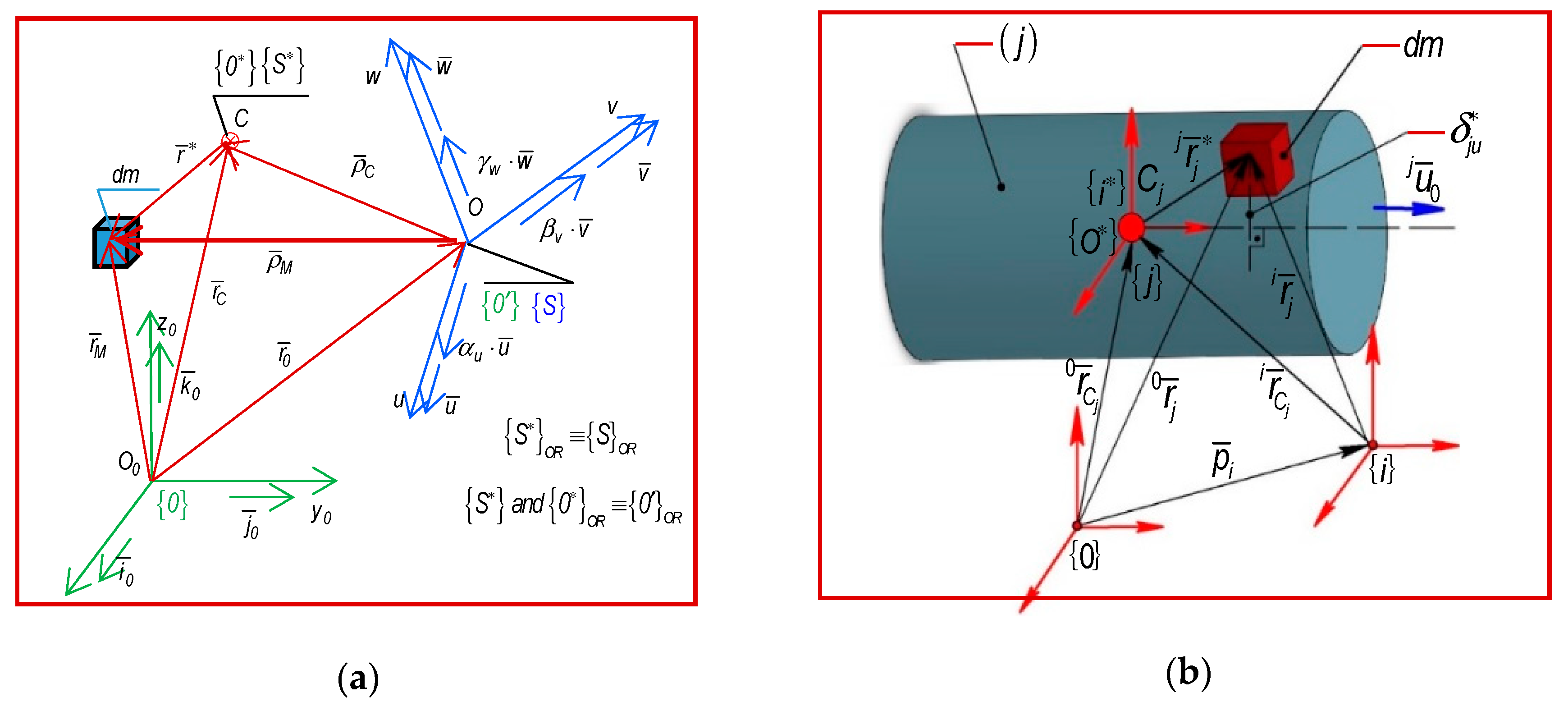
Equation (56) defines the acceleration energy of order p = 1 , 2 , 3 , corresponding to the whole mechanical system. The symbols from Equation (56) have the following meaning: ( p ) and ( p + 1 ) represent the order of the absolute time derivatives; i r ¯ i is the position vector of the elementary mass d m , relative to a reference frame { i } applied in the mass center; r ¯ ( i ) C i defines the position vector of the mass center projected on the fixed { 0 } or moving { i } reference frame (Figure 2b); [ R ] i 0 is the orientation matrix between the two reference systems. A mechanical system is characterized by “n” degrees of freedom (d.o.f.) or generalized coordinates, which are included in the column matrix θ ¯ ( t ) = ( q i ( t ) , f o r   i = 1 n ) T . Further, it should be noted that the expressions of acceleration energies of the first, second, third, and fourth orders were determined in a previous paper [4], in an explicit form, and by using mass integrals. In this section, the matrix form of acceleration energies of higher orders is presented exclusively. An important issue that must be mentioned is that the dynamics matrices have to be included in these expressions. The dynamics matrices comprise the differential matrices from the advanced kinematics, written with matrix exponentials and developed in the Section 2.

4.1. The Acceleration Energy of the First Order

Using Equation (56) as the starting equation, and by applying some successive matrix transformations, the defining expression for the acceleration energies of first order is obtained. This expression can be written in a matrix form as follows:
E A ( 1 ) [ θ ¯ ( t ) ; θ ¯ ˙ ( t ) ; θ ¯ ¨ ( t ) ] = 1 2 { θ ¯ ¨ T ( t ) M [ θ ¯ ( t ) ] θ ¯ ¨ ( t ) + θ ¯ ¨ T ( t ) V [ θ ¯ ( t ) ; θ ¯ ˙ 2 ( t ) ] + [ θ ¯ ˙ T ( t ) D [ θ ¯ ( t ) ; θ ¯ ˙ 2 ( t ) ] θ ¯ ˙ ( t ) ] } .
Equation (57) includes the column vector of the generalized velocities and accelerations whose components are represented by the first and second-order time derivatives of the column matrix of generalized variables { θ ¯ ( t ) ,   θ ¯ ˙ ( t ) ,   θ ¯ ¨ ( t ) } (see (9)). Also in the expression (57) a set of dynamics matrices, is noticed, and they are defined as follows:
M [ θ ¯ ( t ) ] ( n × n ) = [ M i j = k = max ( i ; j ) n T r a c e [ A k i I k p s k A k j T ]   ,   i = 1 n ,   j = 1 n ] ,
V [ θ ¯ ( t ) ; θ ¯ ˙ 2 ( t ) ] ( n × 1 ) = [ V i [ θ ¯ ( t ) ; θ ¯ ˙ 2 ( t ) ] ,   i = 1 n ] .
Equation (58) defines a ( n × n ) matrix, called the mass matrix or the inertia matrix of the acceleration energies of the first order, whose components denoted with M i j are also defined.
The column matrix of centrifugal and Coriolis terms of the first-order is defined by Equation (60) as an ( n × 1 ) matrix, having the following components:
V i [ θ ¯ ( t ) ; θ ¯ ˙ 2 ( t ) ] = θ ¯ ˙ T [ V i j m = k = max   ( j ; m ) n T r a c e [ A k i I k p s k A k j m T ] ,   w h e r e j = 1 n ,   m = 1 n   ] θ ¯ ˙ .
The pseudo inertial matrix corresponding to the acceleration energies of first order is defined as:
D [ θ ¯ ( t ) ; θ ¯ ˙ 2 ( t ) ] = θ ¯ ˙ T [ D i j l m = k = max   ( i ; j ; l ; m ) n T r [ A k i j I k p s k A k l m T ] ] θ ¯ ˙ ,   w h e r e   { i = 1 n ,   j = 1 n l = 1 n ,   m = 1 n } .
This notices that Equations (57) and (61) include the so-called differential matrices of first and second-order denoted with A k i and A k j m , respectively. Their components are determined according to Equations (40)–(42) in the case of the differential matrices of first-order ( A k i ), while as for the differential matrices of second order, the Equations (43)–(45) are applied.
According to [4], the mass properties (Figure 2), are included in the dynamic matrices using the pseudo-inertial tensor, denoted with I k p s k and defined as follows:
I k p s k ( 4 × 4 ) = [ r ¯ k k r ¯ k k T d m r ¯ k k d m r ¯ k k T d m d m ] = [ I k p k M k r ¯ k C k M k r ¯ k C k T M k ]  
w h e r e I k p k = j = 1 p k σ j I k p j = [ I k x x I k x y I k x z I k y x I k y y I k y z I k z x I k z y I k z z ] , a n d r ¯ k C k = 1 M k ( j = 1 p k σ j r ¯ k C j m j ) , M k = j = 1 p k σ j m j , ( j = 1 p i N ) ( i = 1 n ) ,   a n d   σ j = { { 1 ; j i } ;   { 1 ; j i } }
Equation (62) shows that the pseudo inertial tensor is a squared ( 4 × 4 ) symmetrical matrix [4]. According to (63), it contains the inertial tensor of planar and centrifugal terms, the static moments, and the total mass of the kinetic ensemble as well.

4.2. The Acceleration Energy of Second-Order

The mechanical systems characterized by fast motions, subjected to the action of external forces and characterized by a time variation law, are defined by linear and angular accelerations of higher order. Unlike the formulations presented in paper [4], where the acceleration energy of the second order was established by using the mass integrals, in the following, the expression of the acceleration energy of second-order, is written in a matrix form as:
E A ( 2 ) [ θ ¯ ( t ) ; θ ¯ ˙ ( t ) ; θ ¯ ¨ ( t ) ; θ ¯ ( t ) ] = 1 2 θ ¯ T ( t ) M [ θ ¯ ( t ) ] θ ¯ ( t ) + 3 θ ¯ T ( t ) V [ θ ¯ ( t ) ; θ ¯ ˙ ( t ) ; θ ¯ ¨ ( t ) ] + + θ ¯ T ( t ) H [ θ ¯ ( t ) ; θ ¯ ˙ 2 ( t ) ] θ ¯ ˙ ( t ) + E A ( 2 ) [ θ ¯ ( t ) ;   θ ¯ ˙ ( t ) ;   θ ¯ ¨ 2 ( t ) ] + E A ( 2 ) [ θ ¯ ( t ) ;   θ ¯ ˙ 6 ( t ) ;   θ ¯ ¨ ( t ) ] .
The components E A ( 2 ) [ θ ¯ ( t ) ;   θ ¯ ˙ ( t ) ;   θ ¯ ¨ 2 ( t ) ] and E A ( 2 ) [ θ ¯ ( t ) ;   θ ¯ ˙ 6 ( t ) ;   θ ¯ ¨ ( t ) ] are not developed in this paper. Their components in explicit form can be found in the research presented in [4].
Equation (64) includes the dynamics matrices of the second order. They are defined as:
V [ θ ¯ ( t ) ; θ ¯ ˙ ( t ) ; θ ¯ ¨ ( t ) ] = [ V i * [ θ ¯ ( t ) ; θ ¯ ˙ ( t ) ; θ ¯ ¨ ( t ) ] ,   w h e r e   i = 1 n ] , a n d   V i * ( n × 1 ) [ θ ¯ ( t ) ; θ ¯ ˙ ( t ) ; θ ¯ ¨ ( t ) ] = θ ¯ ¨ T [ { V i j m = V i m j } , w h e r e   j = 1 n   a n d   m = 1 n ] θ ¯ ˙ ,
H [ θ ¯ ( t )   ;   θ ¯ ˙ 2 ( t ) ] ( n × n ) = [ H i j [ θ ¯ ( t ) ;   θ ¯ ˙ 2 ( t ) ] ,   w h e r e i = 1 n   a n d   j = 1 n ] ,
H i j [ θ ¯ ( t ) ; θ ¯ ˙ 2 ( t ) ] = θ ¯ ˙ T [ H i j l m = k = max   ( i ; j ; l ; m ) n T r [ A k i I k p s k A k j l m T ] ,   l = 1 n   ,   m = 1 n ] θ ¯ ˙ .
Therefore, along with the inertia matrix and the matrix of Coriolis and centrifugal terms, in the expression for the acceleration energy of second-order acceleration, the pseudo inertial matrix H [ θ ¯ ( t )   ;   θ ¯ ˙ 2 ( t ) ] ( n × n ) , defined by Equations (66) and (67) can also be found.

4.3. The Acceleration Energy of Third-Order

Based on the preliminary aspects presented in the Section 4.2, referring to the fast motion which characterizes the mechanical systems subjected to the action of a system of external forces with a time variation law, the dynamic study is extended to the acceleration energy of third order. As mentioned before, the explicit form of the acceleration energy of the third-order was presented in the paper [4]. According to [3], an equation for defining the acceleration energy of third order in matrix form, as a function which depends exclusively of θ ¯ = ( q   i ,   i = 1 n ) T , is presented:
E A ( 3 ) [ θ ¯ ( t ) ; θ ¯ ˙ ( t ) ; θ ¯ ¨ ( t ) ; θ ¯ ( t ) ; θ ¯ ( t ) ] = 1 2 θ ¯ T ( t ) M [ θ ¯ ( t ) ] θ ¯ ( t ) + 4 θ ¯ T ( t ) V [ θ ¯ ( t ) ; θ ¯ ˙ ( t ) ; θ ¯ ( t ) ] + + 3 θ ¯ T ( t ) V [ θ ¯ ( t ) ; θ ¯ ¨ 2 ( t ) ] + 6 θ ¯ T ( t ) H [ θ ¯ ( t ) ; θ ¯ ˙ 2 ( t ) ] θ ¯ ¨ ( t ) + θ ¯ T ( t ) K [ θ ¯ ( t ) ; θ ¯ ˙ 4 ( t ) ] .
The dynamics matrices of the third order, included in the acceleration energy of third order, have the following expressions of definition:
V [ θ ¯ ( t ) ; θ ¯ ˙ ( t ) ; θ ¯ ( t ) ] = M a t r i x ( n × 1 ) {   θ ¯ T [ V i j m ,   w h e r e   i = 1 n ,   j = 1 n ,   m = 1 n ] θ ¯ ˙   } T ,
V   [ θ ¯ ( t ) ; θ ¯ ¨ 2 ( t ) ] = M a t r i x ( n × 1 ) {   θ ¯ ¨ T [ V i j m ,   w h e r e   i = 1 n ,   j = 1 n ,   m = 1 n ] θ ¯ ¨   } T ,
H [ θ ¯ ( t ) ; θ ¯ ˙ 2 ( t ) ] = M a t r i x ( n × n ) {   H i j [ θ ¯ ( t ) ; θ ¯ ˙ 2 ( t ) ] ,   w h e r e i = 1 n ,   j = 1 n } ,
H i j [ θ ¯ ( t ) ; θ ¯ ˙ 2 ( t ) ] = θ ¯ ˙ T [ H i j l m ,   w h e r e l = 1 n ,   m = 1 n   ] θ ¯ ˙ ,
K [ θ ¯ ( t ) ; θ ¯ ˙ 4 ( t ) ] = M a t r i x ( n × 1 ) { K i [ θ ¯ ( t ) ; θ ¯ ˙ 4 ( t ) ]   ,   w h e r e   i = 1 n   } T ,
K i [ θ ¯ ( t ) ; θ ¯ ˙ 4 ( t ) ] = θ ¯ ˙ T { θ ¯ ˙ T [ K i j l m p ,   j = 1 n ,   l = 1 n ,   m = 1 n ,   p = 1 n ] θ ¯ ˙ } θ ¯ ˙ ,
w h e r e   K i j l m p = k = max   ( i ; j ; l ; m ; p ) n T r [ A k i I k p s k A k j l m p T ] .
It should be noted that, in case of the acceleration energy of third-order, the mass properties are defined by the pseudo inertial tensor and higher-order differential matrices A j k l m and A j k l m p . The last two matrices are defined based on Equations (46)–(55) from the Section 3.
Likewise, Equation (68) comprises the pseudo-inertial matrix of third order, which is defined according to Equations (73)–(75), previously presented.

5. The Advanced Dynamics Equations

The advanced equations from the dynamics of the current and fast motions of the mechanical systems, according to differential principles from analytical dynamics of systems, are based on the advanced notions of dynamics: generalized driving and inertia forces, as well as the acceleration energies, along with their higher orders time derivatives.
Advanced notions are developed in direct correlation with generalized variables which univocally characterize the holonomic systems (robot mechanical structure). In analytical mechanics, the advanced notions are substituted into the dynamic equations of higher order, thus obtaining the time variation laws for the generalized forces.

5.1. The Generalized Forces of Higher-Order

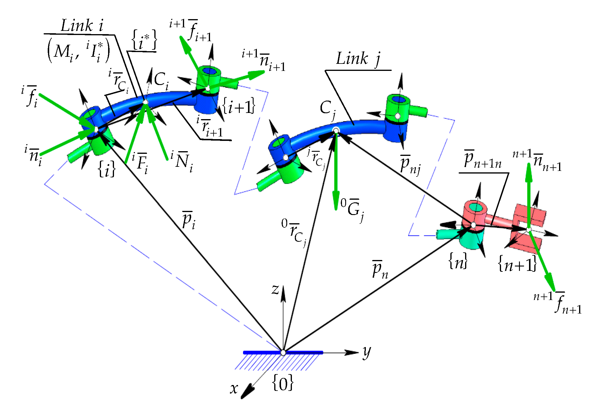
According to [34,35,36,37], on every kinetic ensemble ( i = 1 n ) belonging to the mechanical structure of the serial robots, a system of external and active forces, manipulating loads, and complex friction forces is applied (see Figure 3).
In what follows, the expressions that define the higher-order derivatives applied to generalized inertia force are presented [34]:
Q i i ( k ) ( t ) = m = 1 k ( k 1 ) ! ( m 1 ) ! ( k m ) ! J 0 i T [ θ ¯ ( t ) ] ( m 1 ) ¯ ¯ X i 0 [ k ( m 1 ) ] = = J 0 i T [ θ ¯ ( t ) ] ¯ ¯ X i 0 ( k ) + m = 1 k 1 ( k 1 ) ! m ! ( k m 1 ) ! J 0 i T [ θ ¯ ( t ) ] ( m ) ¯ ¯ X i 0 [ k m ] ,
w h e r e ¯ ¯ X i 0 = [ F ¯ X i T 0 N ¯ X i T 0 ] T , a n d F ¯ X i 0 = j = i n [ R ] j 0 F ¯ j j ,   N ¯ X i 0 = j = i n { ( r ¯ C j 0 p ¯ n )   × [ R ] j 0 F ¯ j j + [ R ] j 0 N ¯ j j } .
Based on the theorem of mass center movement (Newton’s Equation) and the theorem of angular momentum relative to the mass center (Euler’s Equation) as well, the symbols F ¯ j j and N ¯ j j contained in Equation (77) represent the components of the inertia forces torsor, defined according to the following expressions:
F ¯ j j = M j v ¯ ˙ C j j , N ¯ j j = ( I j j   ω ¯ ˙ j j + ω ¯ j j × I j j ω ¯ j j ) ,  
w h e r e j v ¯ ˙ C j = j v ¯ ˙ j + ω ¯ ˙ j j × r ¯ j C j + ω ¯ j j × ω ¯ j j × r ¯ j C j , f o r   i = 1 , v ¯ ˙ 0 0 g ¯ = τ g k ¯ 0 .
In the expressions presented above, v ¯ ˙ j C j is the linear acceleration of mass center, ω ¯ j j and ω ¯ ˙ j j define the angular velocities and accelerations of each kinetic ensemble ( i ) , and I j j the inertial tensor axial and centrifugal relative to { j } frame attached to the mass center of each kinetic ensemble. Further, the expressions for the higher-order derivatives of the generalized gravitational forces by considering the dynamic behavior of each driving joint are developed:
Q g i ( t ) ( k ) = m = 1 k ( k 1 ) ! ( m 1 ) ! ( k m ) ! J 0 i T [ θ ¯ ( t ) ] ( m 1 ) ¯ ¯ 0 X i [ k ( m 1 ) ] = J 0 i T [ θ ¯ ( t ) ] ¯ ¯ 0 X i ( k ) + m = 1 k 1 ( k 1 ) ! m ! ( k m 1 ) ! J 0 i T [ θ ¯ ( t ) ] ( m ) ¯ ¯ 0 X i [ k m ] ,
( n ) 0 ö ¯ ¯ X i ( 6 × 1 ) = [ F ¯ X i T ( n ) 0 N ¯ X i T ( n ) 0 ] T , w h e r e F ¯ X i ( n ) 0 = j = i n M j [ R ] n ( 0 ) n T g ¯ , N ¯ ( n ) 0 X i = j = i n M j [ R ] n ( 0 ) n T [ ( r ¯ 0 C j p ¯ n )   × g ¯ ] ,
a n d g ¯ = τ g k ¯ 0 , τ = k ¯ 0 T k ¯ g , k ¯ g = g ¯ 0 / | g ¯ 0 | , k ¯ 0 v e r t i c a l   u n i t   v e c t o r { 0 } .
The column vector (81), defined relative to the Cartesian space, is mechanically equivalent with a reduction torsor of gravitational forces in the interval [ i   ; n ] , relative to the { n } frame (Figure 4). This frame is attached to the geometrical center of the last driving joint belonging to the robot structure (Figure 3 and Figure 4).
Further, the higher-order derivative of the generalized handling (manipulating) force is defined:
Q S U ( k ) [ θ ¯ ( t ) ] = m = 1 k ( k 1 ) ! ( m 1 ) ! ( k m ) ! J 0 T [ θ ¯ ( t ) ] ( m 1 ) ¯ ¯ X 0 [ k ( m 1 ) ] = J 0 T [ θ ¯ ( t ) ] ¯ ¯ X 0 ( k ) + m = 1 k 1 ( k 1 ) ! m ! ( k m 1 ) ! J T 0 [ θ ¯ ( t ) ] ( m ) ¯ ¯ X 0 [ k m ] ,
w h e r e   ¯ ¯ X ( 6 × 1 ) 0 = [ F ¯ X T 0 N ¯ X T 0 ] T = [ [ R ] n + 1 ( n ) 0 [ 0 ] ( 3 × 3 ) { [ R ] n ( 0 ) n T p ¯ n + 1 n × } [ R ] n + 1 n [ R ] n + 1 ( 0 ) n ] [ f ¯ n + 1 n + 1 n ¯ n + 1 n + 1 ]
The column vector [ n + 1 f ¯ n + 1 n + 1 n ¯ n + 1 ] T represents the reduction torsor for the handling forces, relative to the frame { n + 1 } , attached in the characteristic point of the end-effector (Figure 3 and Figure 4), its components being well defined. It can be noticed that within these expressions, the Jacobian matrix along with its higher-order time derivatives, is found (see Equations (33) and (36)). In the same expressions, ( k ) and ( m ) represent the time deriving orders, where k 1 and m k + 1 . Considering the differential principles in generalized form (a generalization of D’Alembert–Lagrange Principle), and by applying some transformations, the expressions for the generalized driving forces are obtained. These forces define the dynamic behavior from every driving joint of the robot’s mechanical structure. Thus, in the case of current movements, the expressions are applied:
Q m i ( t ) = Δ m 2 [ Δ θ Q i ö i ( t ) + Q g i ( t ) ] + ( 1 ) Δ m 1 Δ m 1 + 3 Δ m Q S U i ( t ) ,
In the expressions above, Δ   m highlights the gravitational loads, by ( M i ) , the payload by ( S U ) and Δ θ defines the behavior of the mechanical system (0—statics; 1—dynamics):
Δ   m = { [ 1 ; ( S U ;   M i ) ] ;   ( 0 ; S U ) ;   ( 1 ;   M i )   } ,   Δ θ = { [ 1 ;   i f   { θ ¯ ˙ ; θ ¯ ¨ } 0 ] ; [ 0 ;   i f   { θ ¯ ˙ ; θ ¯ ¨ } = 0 ] } .
In the case of fast motions, the higher-order time derivatives are applied on (85), resulting in:
Q m i ( k 1 ) [ θ ¯ ( t ) ; θ ¯ ˙ ( t ) ; ; θ ¯ ( t ) ( m ) ] = Δ m 2 [ Δ θ Q i i ( k 1 ) ( t ) + Q g i ( k 1 ) ( t ) ] + ( 1 ) Δ m 1 Δ m 1 + 3 Δ m Q S U i ( k 1 ) ( t ) .
Expression (87) includes the higher-order time derivatives of the generalized forces above-defined.

5.2. The Generalized Inertia Forces of Higher-Order

Based on the D’Alembert–Lagrange principle, corresponding to holonomic systems, the Lagrange equations of the first and second kind, specific to conservative and non-conservative systems, are developed. These lead to the second-order equations corresponding to the degrees of freedom of a mechanical system subjected to current movements.
d d t ( K E q ˙ j ) K E q j = Q j ,   w h e r e   j = 1 n .
Therefore, the Lagrange equations cannot highlight the existence of accelerations of higher-order. In scientific literature, the generalization of Lagrange equations has been developed. The generalization is known as Mangeron–Tsenov development and is defined in the form:
1 m [ K E ( m ) q j ( m ) ( m + 1 ) K E q j ] = Q j .
In Equations (88) and (89), K E represents the kinetic energy, q j is the generalized coordinate (d.o.f), Q j defines the generalized inertia forces developed in the mechanical system, and m 2 is the time deriving order. According to D’Alembert–Lagrange principle, the generalized inertia forces, defined at first according to Equation (76), are equivalent to:
Q i ö j [ θ ¯ ( t ) , θ ¯ ˙ ( t ) ,   θ ¯ ¨ ( t ) ] = d d t ( K E q ˙ j ) K E q j = 1 m [ K E ( m ) q j ( m ) ( m + 1 ) K E q j ] .
An alternative to Lagrange’s equations of the second kind is the Gibbs–Appel equations customized for holonomic mechanical systems, which leads to the same differential equations of motion as the ones defined according to Equation (88):
E A ( 1 ) q ¨ j = Q j ,   w h e r e   j = 1 n .
Similar to Equation (89), to emphasize the higher-order acceleration, a series of differential transformations were conducted on the Gibbs–Appell’s equations, finally resulting in:
E A ( 1 ) ( m 2 ) q j ( m ) = Q j ,   w h e r e   j = 1 n
As a result of the mathematical equivalence of relations in Equations (88), (89), (91) and (92) and considering (90) as well, the generalized inertial forces are defined as a function of the first order acceleration energies.
Q i j [ θ ¯ ( t ) ; θ ¯ ˙ ( t ) ; θ ¯ ( t ) ( 2 ) ] = q j ( m )   { E A ( 1 ) ( m 2 ) [ θ ¯ ( t ) ; θ ¯ ˙ ( t ) ; θ ¯ ¨ ( t ) ; ; θ ¯ ( m ) ( t ) ] } , w h e r e E A ( 1 ) ( 0 ) = E A ( 1 )   ,   j = 1 n ,   k = 1   ,   m [ ( k + 1 ) = 2 ]   ,   a n d   ( k )   a r e   t h e   t i m e   d e r i v i n g   o r d e r s .
The differential expressions (93) represent a generalization of the Gibbs Appell equations because they include the accelerations of higher-order ( q j ( m ) ) and the higher-order time derivatives of the acceleration energies ( E A ( 1 ) ( m 2 ) ). Further, taking into account [34], the higher-order differential equations of motion, defined only by the components corresponding to generalized inertia forces, are presented.
Q i j ( 1 ) [ θ ¯ ( t ) ; θ ¯ ˙ ( t ) ; ; θ ¯ ( t ) ( m ) ] = d d   t {   E A ( 1 ) ( m 2 ) q j ( m ) } = 1 m + 1 q j ( m ) [ 2 E A ( 2 ) ( m 3 ) + E A ( 1 ) ( m 1 ) ] ,
Q i j ( 2 ) [ θ ¯ ( t ) ; θ ¯ ˙ ( t ) ; ; θ ¯ ( t ) ( m ) ] = d 2 d   t 2 {   E A ( 1 ) ( m 2 ) q j ( m ) } = = 2 ( m + 1 ) ( m + 2 ) q j ( m ) [ 5 E A ( 3 ) ( m 4 ) + 2 E A ( 2 ) ( m 2 ) + E A ( 1 ) ( m ) ] , w h e r e j = 1 n   ,   k = 3 ,   m [ ( k + 1 ) = 4 ] ,   m = 4 , 5 , 6 ,   a n d   E A ( 3 ) ( 0 ) = E A ( 3 ) ,
Q i j ( 3 ) [ θ ¯ ( t ) ; θ ¯ ˙ ( t ) ; ; θ ¯ ( t ) ( m ) ] = d 3 d   t 3 {   E A ( 1 ) ( m 2 ) q j ( m ) } = δ Q q j ( m ) [ 9 E A ( 4 ) ( m 5 ) + 5 E A ( 3 ) ( m 3 ) + 2 E A ( 2 ) ( m 1 ) + E A ( 1 ) ( m + 1 ) ] , w h e r e δ Q = 2 3 ( m + 1 ) ( m + 2 ) ( m + 3 ) = ( k 1 ) ! m ! ( m + k 1 ) ! , a n d   j = 1 n   ,   k = 4 ,   m [ ( k + 1 ) = 5 ] ,   m = 5 , 6 , 7 ,   a n d   E A ( 4 ) ( 0 ) = E A ( 4 )
Finally, the differential equations of motion of higher-order results in a generalized form:
Q i j ( k 1 ) [ θ ¯ ( t ) ; θ ¯ ˙ ( t ) ; ; θ ¯ ( t ) ( m ) ] = d   k 1 d   t k 1 {   E A ( 1 ) ( m 2 ) q j ( m ) } = ( k 1 ) ! m ! ( m + k 1 ) ! q j ( m ) { ( p = 1 k   Δ p ) E A ( p ) ( m + k ) ( 2 p + 1 ) } ,
w h e r e E A ( p ) = E A ( p ) [ θ ¯ ( t ) ; θ ¯ ˙ ( t ) ; ; θ ¯ ( t ) ( p + 1 ) ] ,   ( p = 1 k   Δ p ) = p = 1 k [ p ( p + 1 ) 2 δ p ] , a n d   p = 1 k ,   δ p = { { 0   ;   p = 1 }   ;   { 1   ;   p > 1 } } ,   k 1 ;   k = { 1 ; 2 ;   3 ;   4 ;   5 ;   .. } ,   m ( k + 1 ) ,   m = { 2 ;   3 ;   4 ;   5 ;   } .
The above expressions are functions of the acceleration energy of higher order. By substituting Equation (97) in (87), the higher-order equations of the advanced dynamics are obtained. By applying the inverse dynamic modeling, the generalized driving forces along with their higher-order time derivatives, which develop within the fast motion of the robot structures, are determined.

6. Application

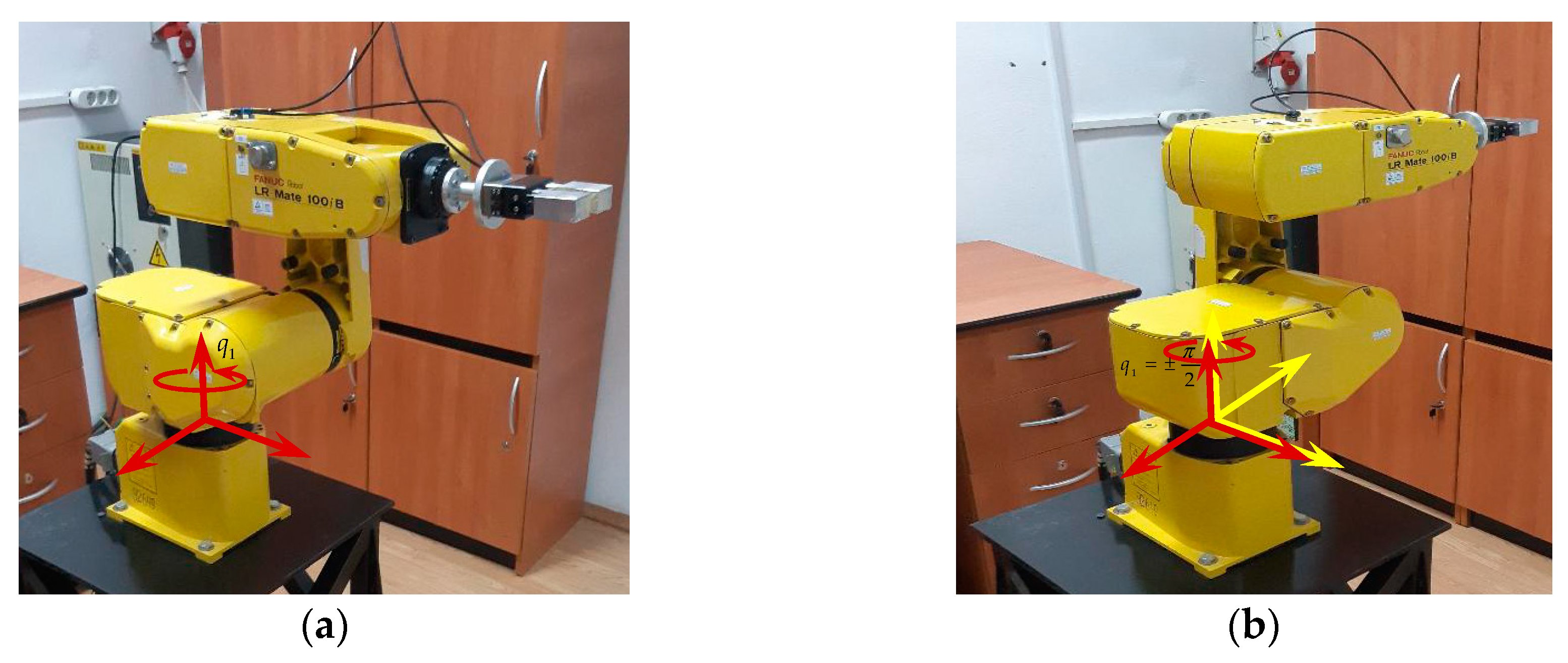
The expressions for the acceleration energies, as well as the differential equations of higher order, are validated by considering an experimental study on a serial robot of type Fanuc LR Mate 100 iB (see Figure 5). The serial robot structure, subjected to the analysis, is mechanically characterized by five degrees of freedom.
The purpose of this experiment is to study the rotation motion of the robot arm in the angular interval ( π 2 ,   π 2 ) , a motion, which is due exclusively to the actuation of the robot’s first driving joint. Using a mono-axial accelerometer, the necessary data for this experiment were collected. By experimental measurements have been established the time variation laws of the tangential acceleration corresponding to a certain point from the robot arm, also named characteristic point [29]. Using the SolidWorks application, the mechanical robot structure and the working environment were modeled. Based on this, the parameters of mass distribution, which are essential in developing the expressions for the driving torques of first, second and third-order, are also determined. Considering the rotation motion of the robot arm, and using the polynomial interpolating functions of a higher order, according to a previous paper [4], the time variation laws for the angular acceleration of first, second and third-order ( q ¨ 1 i k ( τ ) ,   q 1 i k ( τ ) ,   q 1 i k ( τ ) ), in analytical and graphical form are determined. To establish the equations of advanced dynamics, Equation (87) is used. According to the inverse dynamic modeling, the unknowns are the generalized driving forces and their time derivatives. For determining the unknowns, the following expressions from the Section 3 of this paper are used: (16)–(18), (23), (30), (36) and (40)–(55). From Section 4, the expressions of the acceleration energies (57), (64) and (68) are used, and from Section 5, the expressions (80), (83), (87) and (93)–(95). Due to the simple rotation around the first driving axis of the Fanuc robot, the expressions of the generalized driving forces take a simple analytical form, as:
Q m i k 1 ( τ ) = E A i k ( 1 ) ( τ )   q ¨ 1 i k ( τ ) + Q g i k 1 ( τ ) = ( M 1 x C 1 2 + M 1 z C 1 2 + I 1 Δ ) q ¨ 1 i k ( τ ) ,
Q ˙ m i k 1 ( τ ) = 1 4 q 1 i k ( τ ) [ 2 E A i k ( 2 ) ( τ ) + E A i k ( 1 ) ( τ )   ( 2 ) ] + Q ˙ g i k 1 ( τ ) = ( M 1 x C 1 2 + M 1 z C 1 2 + I 1 Δ ) q 1 i k ( τ ) ,
{ Q ¨ m i k 1 ( τ ) = 1 15 q   1 i k ( τ ) [ 5 E A i k ( 3 ) ( τ ) + 2 E A i k ( 2 ) ( τ ) ( 2 ) + E A i k ( 1 ) ( τ )   ( 4 ) ] + Q ¨ g i k 1 ( τ ) = = ( M 1 x C 1 2 + M 1 z C 1 2 + I 1 Δ ) q   1 i k ( τ ) } ,
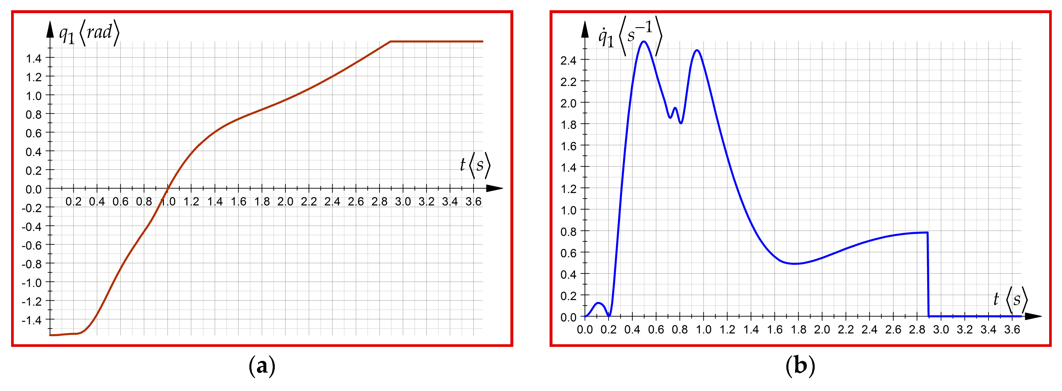
where Q m i k 1 , Q ˙ m i k 1 and Q ¨ m i k 1 are driving torques of first, second and third-order, M 1 is the mass of the robot arm, x C 1 ,   z C 1 are mass center coordinates, I 1 Δ is the axial inertia moment, and q 1 ( m ) ,   w h e r e   m = 2 , 3 , 4 are the angular accelerations of first, second and third-order, corresponding to rotation motion for each segment of the motion trajectory in angular range [ π 2 ,   π 2 ] . The term q ¨ 1 ( τ ) was determined by measurements (see Figure 5), while q 1 i k ( τ ) and q 1 i k ( τ ) were obtained by applying the polynomial interpolation functions of fifth-degree [4]. Considering the previous expressions (see Equations (99)–(101)), in Figure 6 and Figure 7, the time variation laws for the generalized coordinates of first, second, or third order, corresponding to the first driving joint of the serial robot structure Fanuc LR Mate100iB are illustrated. To obtain the graphical representation for the variation in time of the generalized coordinate, q 1 the polynomial functions of the fifth-order were applied according to [4].
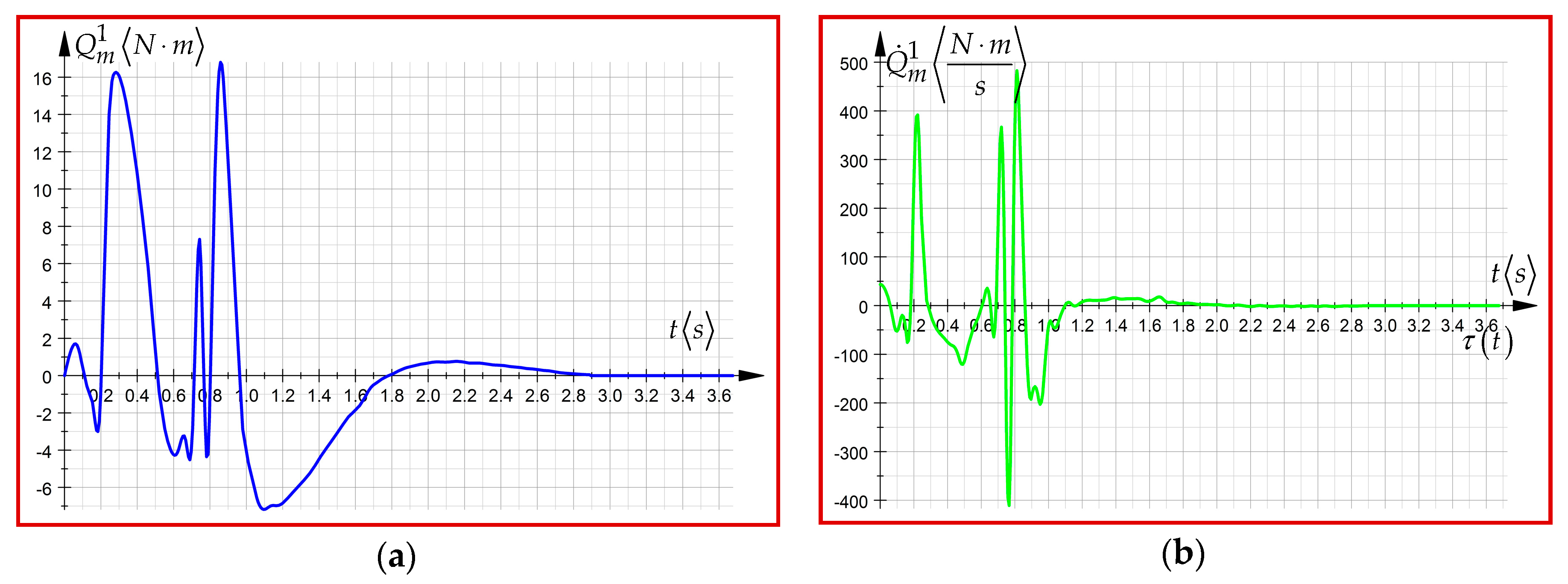
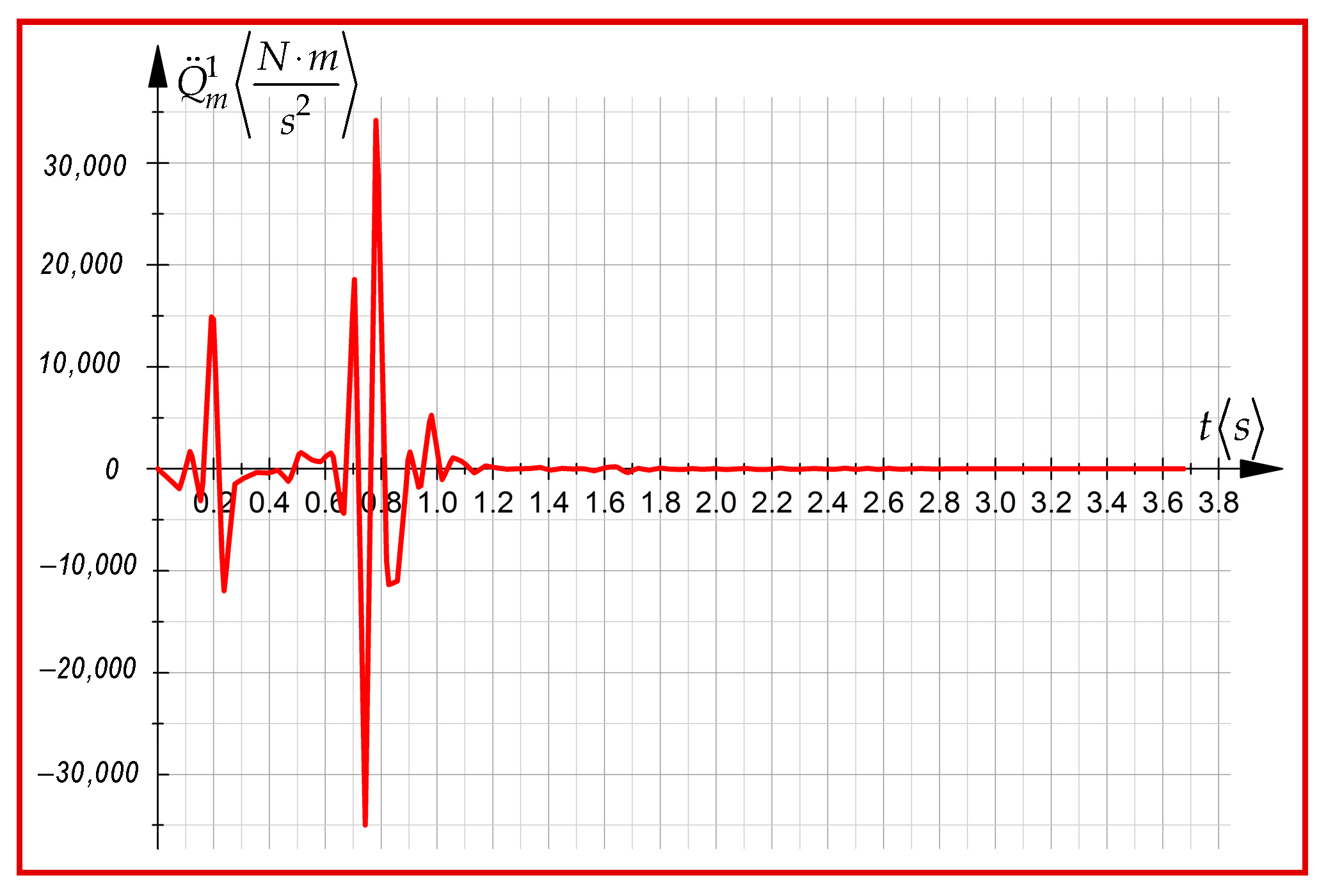
In Figure 8 and Figure 9 the time variation laws of the driving torque of the first, second and third-order are illustrated, corresponding to the first driving joint, by considering the physical characteristics of the Fanuc robot, (Figure 5), and the variation laws of the generalized variables, as well (see Figure 6 and Figure 7).
The main objective of this section was to illustrate the necessity for approaching the advanced dynamics equations in characterizing the dynamic behavior of the complex mechanical systems subjected to fast motions. Based on the data collected from experimental measurements, the time variation laws corresponding to the angular accelerations from the first driving axis of the robot were obtained. Further, applying the polynomial functions of higher orders, the laws of variation for the higher-order angular accelerations were also established. The results were included in the expression of the generalized driving force. Thus, the time variation laws of the generalized driving force and of its first, second, and third-order time derivatives, corresponding to the rotation motion of the robot arm were obtained.

7. Conclusions

The present paper focuses on some important approaches regarding the analytical dynamics of the mechanical systems subordinated to the transient regimes and the fast movements.
According to the authors and [4], the fast movements occur in the situation where the linear acceleration meets the condition: a 2 g .
The main purpose of the paper was to present the defining matrix expressions for the acceleration energies of higher-order and their use in the advanced dynamics equations, characterized by differential equations of motion of higher order. To reach this objective, in Section 2 and Section 3 of this paper, a series of expressions that later became input values in the study of the energies of accelerations, essential components of the dynamic equations, were presented. Thus, in Section 2, some expressions dedicated to homogeneous transformations (1)–(3), which refer to homogeneous transformation matrices and their components, based on matrix exponentials, were synthesized. According to (36), in the next section, the expressions of the Jacobian matrix and of its time derivatives were established. The advanced kinematic Equations (38) and (39) that highlight the presence of higher-order accelerations in the serial robot structures were also determined. In the expressions mentioned above, the presence of the matrix exponentials should be noticed. They are characterized by important advantages due to the unitary form, and also by the fact that they do not use reference systems, which usually introduce geometric restrictions. In the same section three, the higher-order differential matrices obtained by using homogeneous transformations and exponential matrix functions (see (40)–(55)) were presented in an analytical form. Their utility is obvious when establishing the dynamics matrices, essential components of the acceleration energies of the first, second and third-order. In the Section 4 of this paper, the matrix expressions for the acceleration energies are presented according to (56), (57), (64) and (68). A fundamental aspect worthy of mention is the fact that the present study, which relates to the establishment of the expressions for the acceleration energies, was carried out by considering the Appell functions as starting equations.
Compared to other research, in this paper, the energies of accelerations are determined for holonomic systems subjected to general motion. Unlike the dynamic equations specific to current movements, the advanced dynamic equations have as a central function the acceleration energies in which the higher-order accelerations, specific to the fast movements, are found. Starting from the Gibbs–Appell equations that characterize the current movements, a generalization of these Equation (92), was presented in the Section 5 of the present paper. In the same section, the differential equations of higher order that highlight the time derivatives of the generalized inertia forces (whose components represented by the acceleration energies of higher-order) are defined according to Equations (94)–(98). Based on the principles from advanced mechanics in robotics, the generalized forces of inertia and their derivatives are an integral part of the equations of advanced dynamics (87). According to the inverse dynamic model, the unknowns were represented by considering the generalized driving forces from each robot joint as well as of their time derivatives. To illustrate the mathematical models previously presented, in Section 6, a simple example applied on a Fanuc type robot was presented. By combining the data obtained from measurements with the analytical expressions of the acceleration energies, the equations of the advanced dynamics were established. These are characterized by the presence of the generalized driving forces (according to Equations (99)–(101)), and they are graphically illustrated in Figure 8 and Figure 9. This simple example illustrates analytically and graphically the existence of higher-order accelerations and their influence on the dynamic behavior of the serial structures of robots, subordinated to either transient or rapid movement regimes.
In conclusion, the novelty of this paper constitute the establishment of the Jacobian matrix, the advanced kinematic equations, and the differential matrices, as well as the higher-order time derivatives of the accelerations by using the matrix exponentials.
Moreover, the novelty of the approach consists in the defining expressions of the acceleration energies, written in the matrix form, as well as by their encompassment in the advanced dynamics equations. These equations define the dynamic behavior of a mechanical system (serial robot) on transient modes and in fast motions.

8. Contributions of the Authors

Therefore, the contributions of the first author are highlighted by a great number of expressions included in the following sections of this paper:
(1)
2. Matrices of the homogenous transformations. The new expressions are (1)–(7);
(2)
3.1. Matrix exponentials in advanced kinematics. New Equations: (18), (23), (25)–(36), (38), (39);
(3)
3.2. The differential matrices in advanced kinematics. New Equations: (41), (42), (44), (46)–(55);
(4)
4. The matrix expressions of the acceleration energies. New expressions: (56)–(61), (64)–(75);
(5)
5. The advanced dynamics equations. New Equations: (76), (80), (83), (85)–(87), (93)–(98).

Author Contributions

Conceptualization, I.N. and S.V.; methodology, I.N.; investigation and software, A.-V.C. and I.N.; validation, I.N.; formal analysis, I.N. and S.V.; resources, I.N. and A.-V.C.; data curation, I.N. and A.-V.C.; writing—original draft preparation, A.-V.C.; writing—review and editing, I.N., A.-V.C. and S.V.; visualization, A.-V.C.; supervision, I.N. and S.V. All authors have read and agreed to the published version of the manuscript.

Funding

This research received no external funding.

Acknowledgments

The authors would like to thank the Technical University of Cluj Napoca, Romania, for providing technical support in carrying out the experimental analysis. At the same time, the authors are grateful to the unknown reviewers and the academic editor for their very useful comments.

Conflicts of Interest

The authors declare no conflict of interest.

References

  1. Eager, D.; Pendrill, A.M.; Reinstad, N. Beyond velocity and acceleration: Jerk, snap and higher derivatives. Eur. J. Phys. 2016, 37, 065008. [Google Scholar] [CrossRef]
  2. Visser, M. Jerk, Snap and the Cosmological Equation of State. Class. Quantum. Grav. 2004, 21, 2603–2616. [Google Scholar] [CrossRef]
  3. Negrean, I.; Negrean, D.C. The Acceleration Energy to Robot Dynamics. In Proceedings of the A&QT-R International Conference on Automation, Quality and Testing, Robotics, Cluj-Napoca, Romania, 23–25 May 2002; pp. 59–64. [Google Scholar]
  4. Negrean, I.; Crișan, A.-V. Synthesis on the Acceleration Energies in the Advanced Mechanics of the Multibody Systems. Symmetry 2019, 11, 1077. [Google Scholar] [CrossRef] [Green Version]
  5. Thompson, P. Snap, Crackle, and Pop; Systems Technology: Hawthorne, CA, USA, 2011. [Google Scholar]
  6. Shojaee, S.; Rostami, S.; Abbasi, A. An unconditionally stable implicit time integration algorithm: Modified quartic B-spline method. Comput. Struct. 2015, 153, 98–111. [Google Scholar] [CrossRef]
  7. Bruner, A.M.; Belvin, W.K.; Horta, L.G.; Juang, J.N. Active Vibration Absorber for the CSI Evolutionary Model–Design and Experimental Results. J. Guid. Control Dyn. 1992, 15, 1253–1257. [Google Scholar] [CrossRef] [Green Version]
  8. Kerkhoven, T.; Saad, Y. On acceleration methods for coupled nonlinear elliptic systems. Numer. Math. 1991, 60, 525–548. [Google Scholar] [CrossRef]
  9. Aghasi, M.; Dodson, C.T.J.; Galanis, G.N.; Suri, A. Infinite-dimensional second order ordinary differential equations via (TM)-M-2. Nonlinear Anal. Theor. 2007, 67, 2829–2838. [Google Scholar] [CrossRef]
  10. Thornbury, A.; Drury, L.O. Power requirements for cosmic ray propagation models involving re-acceleration and comment on second-order Fermi acceleration theory. Mon. Not. R. Astron. Soc. 2012, 442, 3010–3012. [Google Scholar] [CrossRef] [Green Version]
  11. Gao, C.J. Generalized modified gravity with the second-order acceleration equation. Phys. Rev. D 2012, 86, 103512. [Google Scholar] [CrossRef] [Green Version]
  12. Allan, W. The Ponderomotive Force of Standing Alfven Waves in a Dipolar Magnetoshere. J. Geophys. Res. Space Phys. 1993, 98, 1409–1417. [Google Scholar] [CrossRef]
  13. Hartquist, T.W.; Morfill, G.E. Cosmic-Ray Diffusion at Energies of 1-MEV to 10(5) GEV. Astrophys. Space Sci. 1994, 216, 223–234. [Google Scholar] [CrossRef]
  14. Wheaton, B.J.; Maybeck, P.S. 2nd-Order Acceleration Models for an MMAE Target Tracker. IEEE Trans. Aerosp. Electron. Syst. 1995, 31, 151–167. [Google Scholar] [CrossRef] [Green Version]
  15. Zhang, J.J.; Rajabhandharaks, D.; Xuan, J.R.; Chia, R.W.J.; Hasenberg, T. Calculus migration characterization during Ho:YAG laser lithotripsy by high-speed camera using suspended pendulum method. Laser Med. Sci. 2017, 32, 1017–1021. [Google Scholar] [CrossRef]
  16. Voltairas, P.A.; Fotiadis, D.I.; Michalis, L.K. An-Harmonic Analysis and the Arterial Pulse. Adv. Top. Scatt. Biomed. Eng. 2009, 30, 125–131. [Google Scholar]
  17. Appell, P. Sur Une Forme Générale des Equations de la Dynamique, 1st ed.; Gauthier-Villars: Paris, France, 1899. [Google Scholar]
  18. Appell, P. Traité de Mécanique Rationnelle, 1st ed.; Garnier Frères: Paris, France, 1903. [Google Scholar]
  19. Kitamura, Y.; Ishioka, K. Equatorial jets in decaying shallow-water turbulence on a rotating sphere. J. Atmos. Sci. 2007, 64, 3340–3353. [Google Scholar] [CrossRef]
  20. Mirtaheri, S.M.; Zohoor, H. The Explicit Gibbs-Appell Equations of Motion for Rigid-Body Constrained Mechanical System; Book Series: RSI International Conference on Robotics and Mechatronics ICRoM; IEEE: Piscataway, NJ, USA, 2018; pp. 304–309. [Google Scholar]
  21. Mehrjooee, O.; Dehkordi, S.F.; Korayem, M.H. Dynamic modeling and extended bifurcation analysis of flexible-link manipulator. Mech. Based Des. Struc. 2019, 6631650. [Google Scholar] [CrossRef]
  22. Shafei, A.M.; Shafei, H.R. A systematic method for the hybrid dynamic modeling of open kinematic chains confined in a closed environment. Multibody Syst. Dyn. 2017, 38, 21–42. [Google Scholar] [CrossRef]
  23. Amini, S.; Dehkordi, S.F.; Fahraji, S.H. Motion equation derivation and tip-over evaluations for K mobile manipulators with the consideration of drivings mass by the use of Gibbs-Appell formulation. In Proceedings of the 5th RSI International Conference on Robotics and Mechatronics (IcRoM), Tehran, Iran, 25–27 October 2017. [Google Scholar]
  24. Korayem, M.H.; Dehkordi, S.F. Derivation of dynamic equation of viscoelastic manipulator with revolute-prismatic joint using recursive Gibbs-Appell formulation. Nonlinear Dynam. 2017, 89, 2041–2064. [Google Scholar] [CrossRef]
  25. Shafei, A.M.; Korayem, M.H. Theoretical and experimental study of dynamic load-carrying capacity for flexible robotic arms in point-to-point motion. Optim. Contr. Appl. Met. 2017, 38, 963–972. [Google Scholar] [CrossRef]
  26. Shafei, A.M.; Shafei, H.R. Oblique Impact of Multi-Flexible-Link Systems. J. Vib. Control 2018, 24, 904–923. [Google Scholar] [CrossRef]
  27. Bachau, O.A. Flexible Multibody Dynamics, 1st ed.; Series: Solid Mechanics and its Applications; Springer: Dordrecht, The Netherlands, 2011; Volume 176, p. 730. [Google Scholar]
  28. Fu, K.S.; Gonzalez, R.C.; Lee, C.G. Control, Sensing, Vision and Intelligence; International Edition; McGraw-Hill Book Co.: Singapore, 1987. [Google Scholar]
  29. Marin, M.; Vlase, S.; Ellahi, R.; Bhatti, M. On the Partition of Energies for the Backward in Time Problem of Thermoelastic Materials with a Dipolar Structure. Symmetry 2019, 11, 863. [Google Scholar] [CrossRef] [Green Version]
  30. Negrean, I.; Negrean, D.C. Matrix Exponentials to Robot Kinematics. In Proceedings of the 17th International Conference on CAD/CAM, Robotics and Factories of the Future, CARS&FOF, Durban, South Africa, 10–12 July 2001; pp. 1250–1257. [Google Scholar]
  31. Park, F.C. Computational Aspects of the Product-of-Exponentials Formula for Robot Kinematics. IEEE Trans. Autom. Control 1994, 39, 643–647. [Google Scholar] [CrossRef]
  32. Jazar, R.N. Theory of Applied Robotics: Kinematics, Dynamics, and Control, 2nd ed.; Springer: Cham/Basel, Switzerland, 2010. [Google Scholar]
  33. Schiehlen, W.; Eberhard, P. Applied Dynamics, 1st ed.; Springer: Cham, Switzerland, 2014; p. 215. [Google Scholar]
  34. Gattringer, H.; Gerstmayr, J. Multibody System Dynamics, Robotics and Control, 1st ed.; Springer: Wien, Austria, 2013; p. 314. [Google Scholar]
  35. Negrean, I. Advanced Equations in Analytical Dynamics of Systems. Acta Tech. Napoc. Ser. Appl. Math. Mech. Eng. 2017, 60, 503–514. [Google Scholar]
  36. Pars, L.A. A Treatise on Analytical Dynamics; Heinemann: London, UK, 2007; Volume 1. [Google Scholar]
  37. Cassel, K. Variational Methods with Applications in Science and Engineering; Cambridge University Press: Cambridge, NY, USA, 2013; p. 413. [Google Scholar]
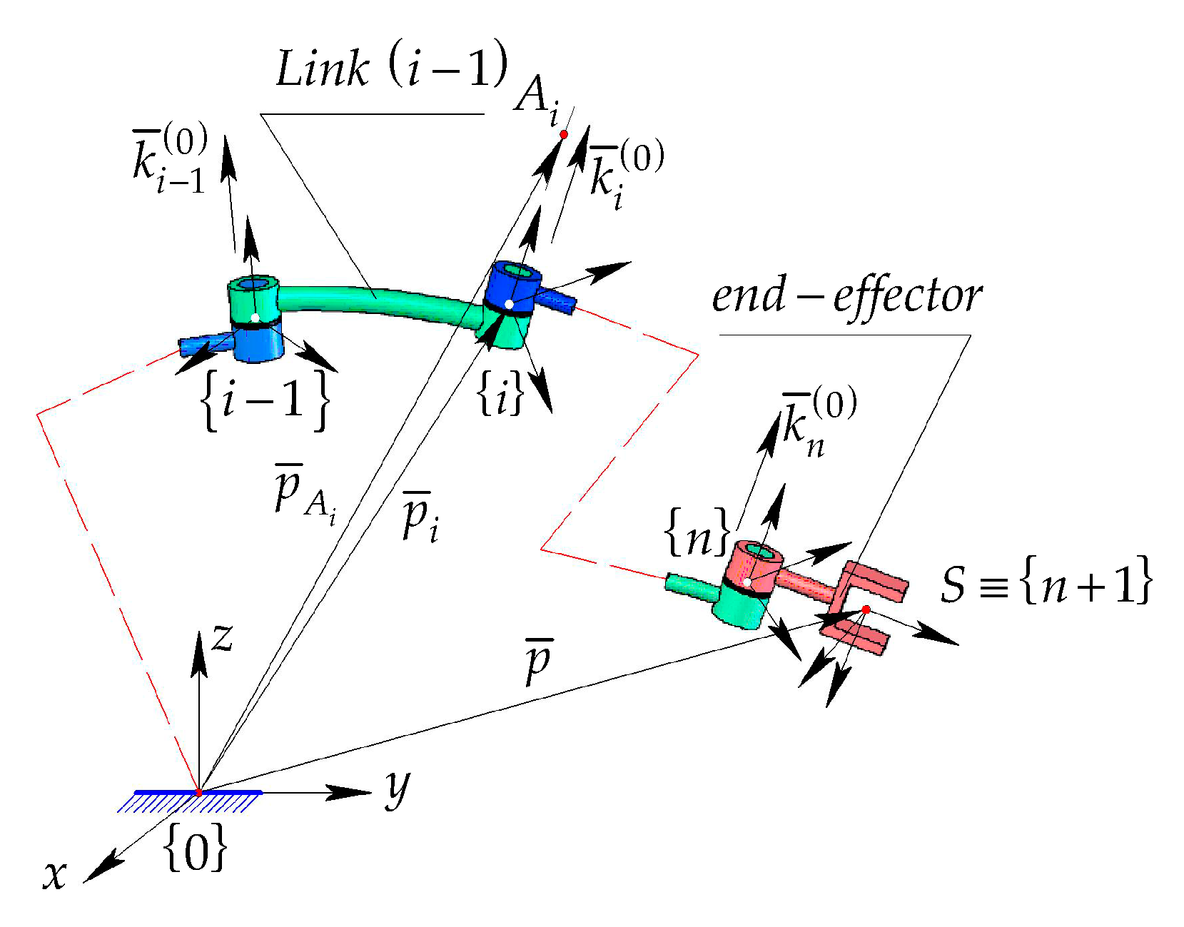
Figure 1. A sequence of kinetic assemblies from a mechanical structure with (n) d. o. f.
Symmetry 12 00095 g001
Figure 2. (a) The frames attached to a solid body and position vectors; (b) The position of the mass center in case of a solid body.
Symmetry 12 00095 g002
Figure 3. The kinematic parameters and the generalized forces.
Symmetry 12 00095 g003
Figure 4. The components of the generalized forces in the case of a mechanical robot structure.
Symmetry 12 00095 g004
Figure 5. The Fanuc LR Mate100iB robot; (a) The initial configuration; (b) The final configuration.
Symmetry 12 00095 g005
Figure 6. (a) The variation law of generalized coordinate ( q 1 ) ; (b) The variation law of the velocity ( q ˙ 1 ) .
Symmetry 12 00095 g006
Figure 7. (a) The variation law of generalized acceleration ( q ¨ 1 ) ; (b) The variation law of the generalized acceleration of first order ( q 1 ) .
Symmetry 12 00095 g007
Figure 8. (a) The variation law of the driving torque of first order from the first driving joint; (b) The variation law of the driving torque of second-order from the first driving joint.
Symmetry 12 00095 g008
Figure 9. The variation law of the driving torque of third order in case of the first joint.
Symmetry 12 00095 g009