Skyrmion Crystals and Phase Transitions in Magneto-Ferroelectric Superlattices: Dzyaloshinskii–Moriya Interaction in a Frustrated J1 − J2 Model


Abstract
1. Introduction
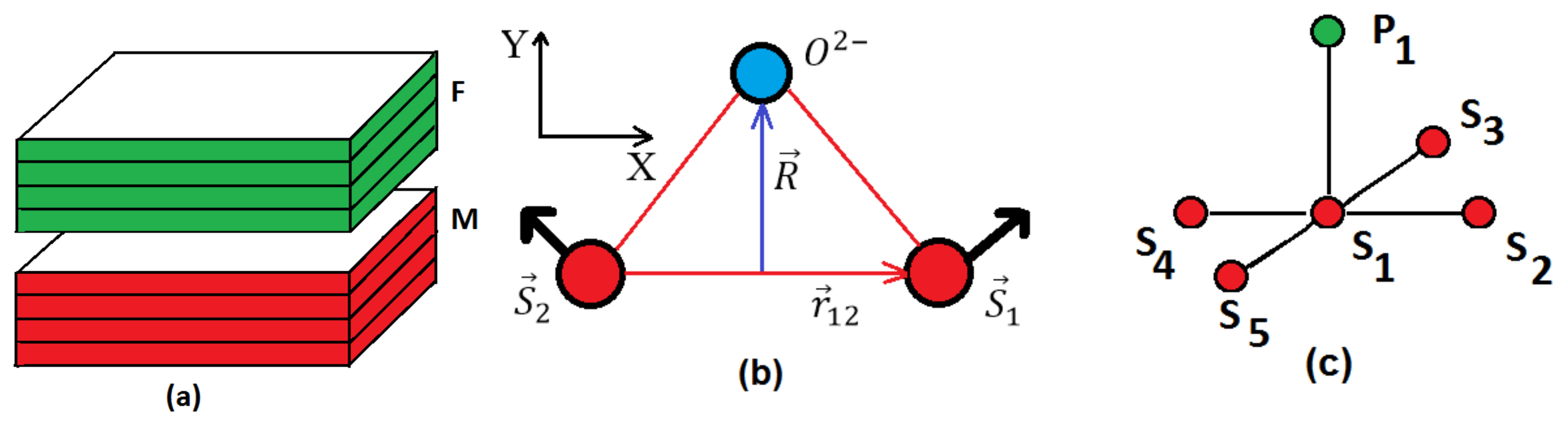
2. Model and Skyrmion Crystal
2.1. Model
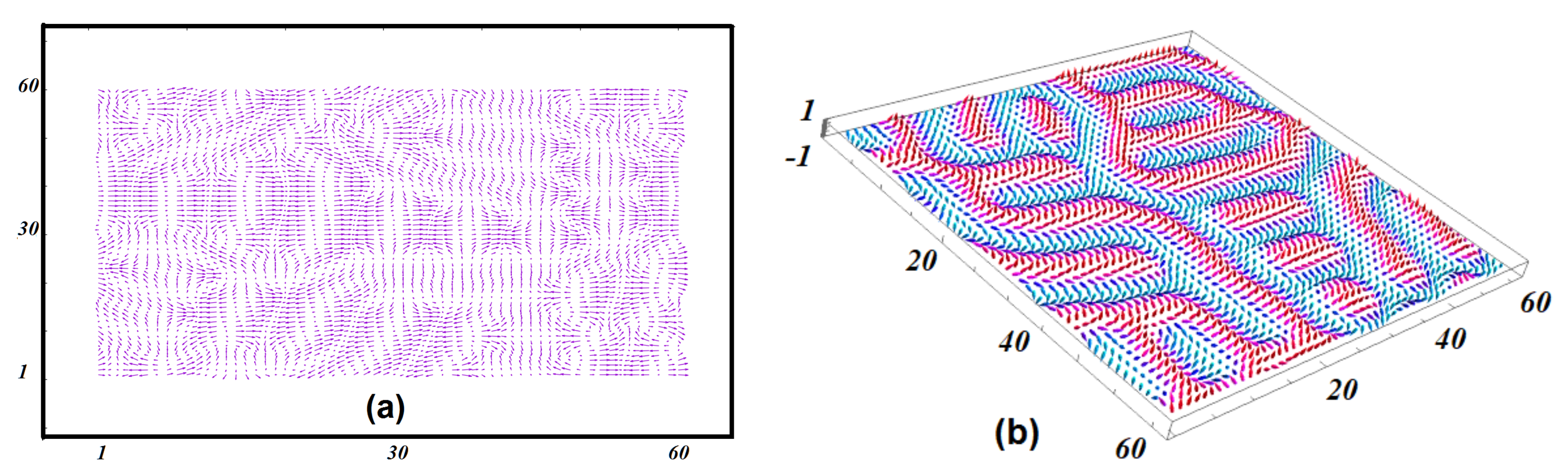
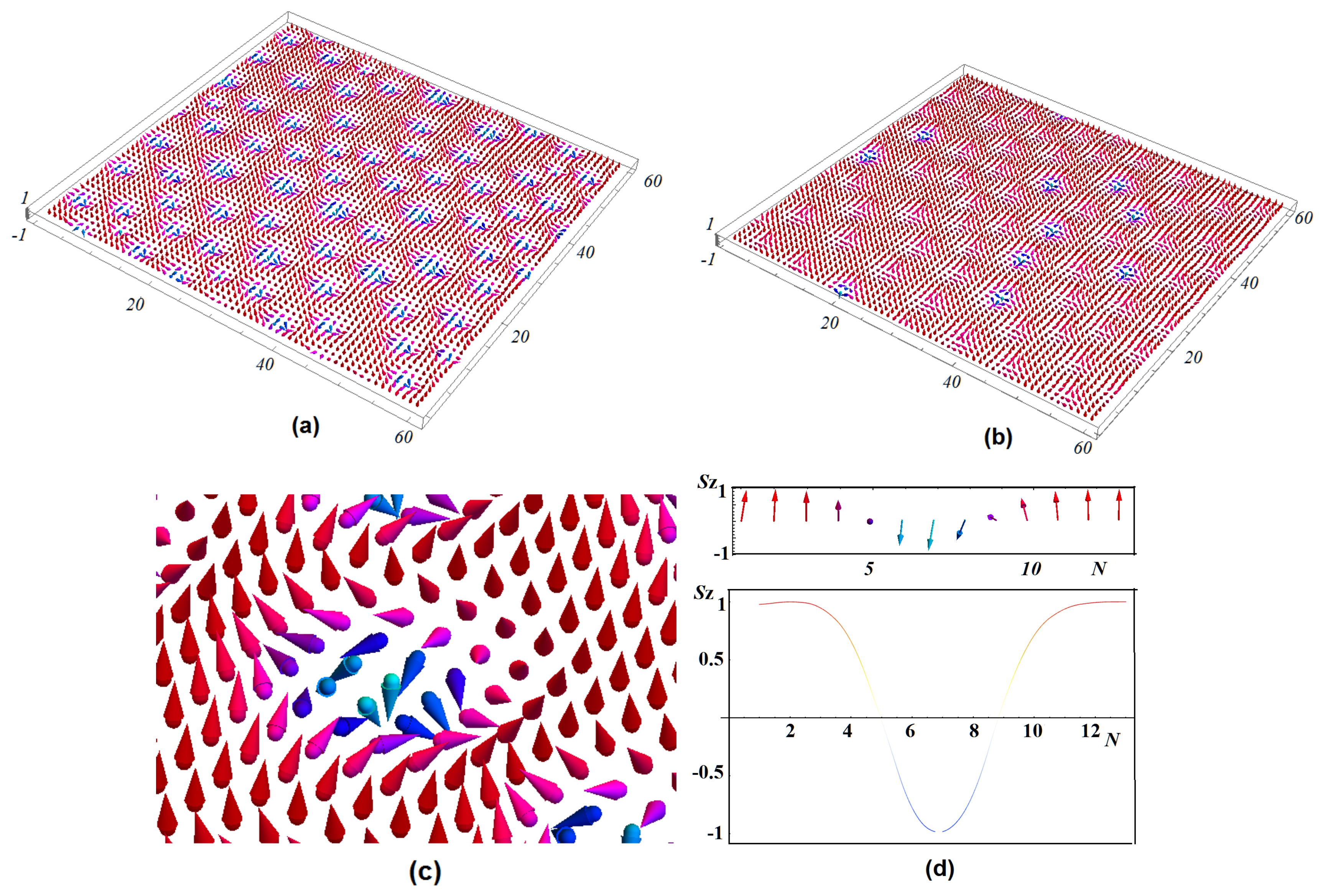
2.2. Ground State
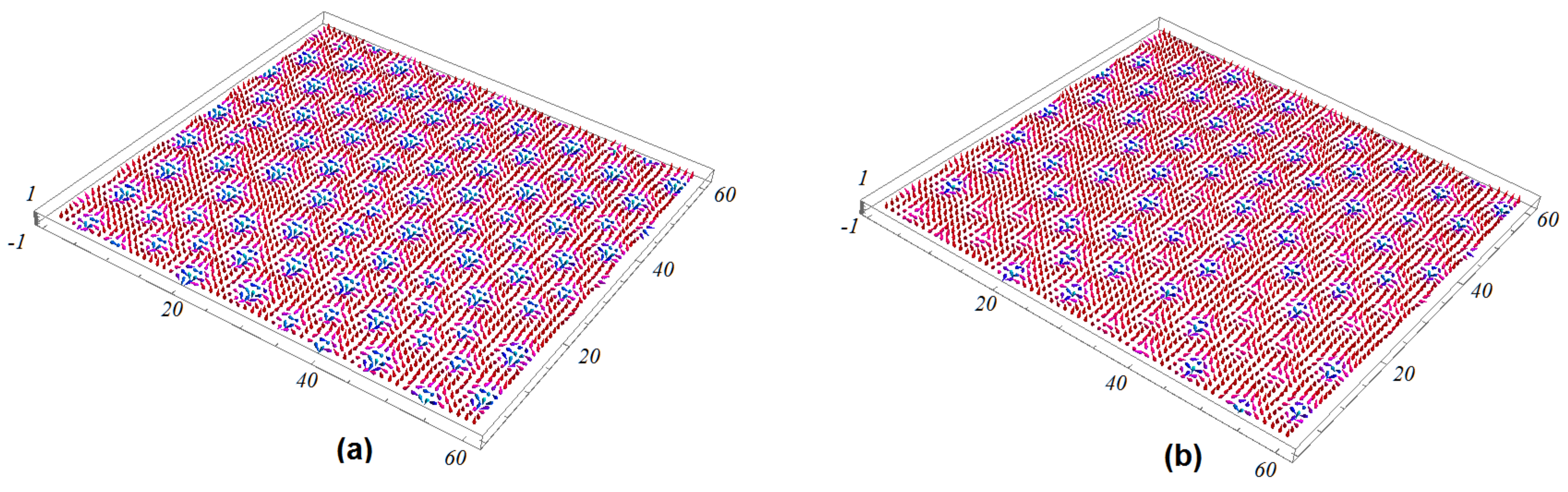
3. Skyrmion Phase Transition
4. Conclusions
Author Contributions
Funding
Conflicts of Interest
References
- Bogdanov, A.N.; Yablonskii, D. Thermodynamically stable vortices in magnetically ordered crystals. The mixed state of magnets. Z. Eksp. Teor. Fiz 1989, 95, 178. [Google Scholar]
- Yu, X.; Onose, Y.; Kanazawa, N.; Park, J.; Han, J.; Matsui, Y.; Nagaosa, N.; Tokura, Y. Real-space observation of a two-dimensional skyrmion crystal. Nature 2010, 465, 901–904. [Google Scholar] [CrossRef] [PubMed]
- Yu, X.; Kanazawa, N.; Onose, Y.; Kimoto, K.; Zhang, W.; Ishiwata, S.; Matsui, Y.; Tokura, Y. Near room-temperature formation of a skyrmion crystal in thin-films of the helimagnet FeGe. Nat. Mater. 2011, 10, 106–109. [Google Scholar] [CrossRef] [PubMed]
- Heinze, S.; Von Bergmann, K.; Menzel, M.; Brede, J.; Kubetzka, A.; Wiesendanger, R.; Bihlmayer, G.; Blügel, S. Spontaneous atomic-scale magnetic skyrmion lattice in two dimensions. Nat. Phys. 2011, 7, 713–718. [Google Scholar] [CrossRef]
- Romming, N.; Hanneken, C.; Menzel, M.; Bickel, J.E.; Wolter, B.; von Bergmann, K.; Kubetzka, A.; Wiesendanger, R. Writing and deleting single magnetic skyrmions. Science 2013, 341, 636–639. [Google Scholar] [CrossRef]
- Rosch, A. Skyrmions: Moving with the current. Nat. Nanotechnol. 2013, 8, 160. [Google Scholar] [CrossRef]
- Leonov, A.; Togawa, Y.; Monchesky, T.; Bogdanov, A.; Kishine, J.; Kousaka, Y.; Miyagawa, M.; Koyama, T.; Akimitsu, J.; Koyama, T.; et al. Chiral surface twists and skyrmion stability in nanolayers of cubic helimagnets. Phys. Rev. Lett. 2016, 117, 087202. [Google Scholar] [CrossRef]
- Moreau-Luchaire, C.; Moutafis, C.; Reyren, N.; Sampaio, J.; Vaz, C.; Van Horne, N.; Bouzehouane, K.; Garcia, K.; Deranlot, C.; Warnicke, P.; et al. Additive interfacial chiral interaction in multilayers for stabilization of small individual skyrmions at room temperature. Nat. Nanotechnol. 2016, 11, 444–448. [Google Scholar] [CrossRef]
- Soumyanarayanan, A.; Raju, M.; Oyarce, A.G.; Tan, A.K.; Im, M.Y.; Petrović, A.P.; Ho, P.; Khoo, K.; Tran, M.; Gan, C.; et al. Tunable room-temperature magnetic skyrmions in Ir/Fe/Co/Pt multilayers. Nat. Mater. 2017, 16, 898–904. [Google Scholar] [CrossRef]
- Dupé, B.; Bihlmayer, G.; Böttcher, M.; Blügel, S.; Heinze, S. Engineering skyrmions in transition-metal multilayers for spintronics. Nat. Commun. 2016, 7, 11779. [Google Scholar] [CrossRef]
- Müller, J.; Rosch, A.; Garst, M. Edge instabilities and skyrmion creation in magnetic layers. New J. Phys. 2016, 18, 065006. [Google Scholar] [CrossRef]
- Rosch, A. Spintronics: Electric control of skyrmions. Nat. Nanotechnol. 2017, 12, 103–104. [Google Scholar] [CrossRef] [PubMed]
- Shen, L.; Xia, J.; Zhao, G.; Zhang, X.; Ezawa, M.; Tretiakov, O.A.; Liu, X.; Zhou, Y. Spin torque nano-oscillators based on antiferromagnetic skyrmions. Appl. Phys. Lett. 2019, 114, 042402. [Google Scholar] [CrossRef]
- Fert, A.; Cros, V.; Sampaio, J. Skyrmions on the track. Nat. Nanotechnol. 2013, 8, 152–156. [Google Scholar] [CrossRef]
- Bessarab, P.; Yudin, D.; Gulevich, D.; Wadley, P.; Titov, M.; Tretiakov, O.A. Stability and lifetime of antiferromagnetic skyrmions. Phys. Rev. B 2019, 99, 140411. [Google Scholar] [CrossRef]
- Tomasello, R.; Martinez, E.; Zivieri, R.; Torres, L.; Carpentieri, M.; Finocchio, G. A strategy for the design of skyrmion racetrack memories. Sci. Rep. 2014, 4, 6784. [Google Scholar] [CrossRef]
- Koshibae, W.; Kaneko, Y.; Iwasaki, J.; Kawasaki, M.; Tokura, Y.; Nagaosa, N. Memory functions of magnetic skyrmions. Jpn. J. Appl. Phys. 2015, 54, 053001. [Google Scholar] [CrossRef]
- Kang, W.; Huang, Y.; Zheng, C.; Lv, W.; Lei, N.; Zhang, Y.; Zhang, X.; Zhou, Y.; Zhao, W. Voltage controlled magnetic skyrmion motion for racetrack memory. Sci. Rep. 2016, 6, 23164. [Google Scholar] [CrossRef]
- Zhang, X.; Xia, J.; Zhou, Y.; Liu, X.; Zhang, H.; Ezawa, M. Skyrmion dynamics in a frustrated ferromagnetic film and current-induced helicity locking-unlocking transition. Nat. Commun. 2017, 8, 1717. [Google Scholar] [CrossRef]
- Mühlbauer, S.; Binz, B.; Jonietz, F.; Pfleiderer, C.; Rosch, A.; Neubauer, A.; Georgii, R.; Böni, P. Skyrmion lattice in a chiral magnet. Science 2009, 323, 915–919. [Google Scholar] [CrossRef]
- Du, H.; Che, R.; Kong, L.; Zhao, X.; Jin, C.; Wang, C.; Yang, J.; Ning, W.; Li, R.; Jin, C.; et al. Edge-mediated skyrmion chain and its collective dynamics in a confined geometry. Nat. Commun. 2015, 6, 8504. [Google Scholar] [CrossRef] [PubMed]
- Jiang, W.; Upadhyaya, P.; Zhang, W.; Yu, G.; Jungfleisch, M.B.; Fradin, F.Y.; Pearson, J.E.; Tserkovnyak, Y.; Wang, K.L.; Heinonen, O.; et al. Blowing magnetic skyrmion bubbles. Science 2015, 349, 283–286. [Google Scholar] [CrossRef] [PubMed]
- Leonov, A.; Monchesky, T.; Romming, N.; Kubetzka, A.; Bogdanov, A.; Wiesendanger, R. The properties of isolated chiral skyrmions in thin magnetic films. New J. Phys. 2016, 18, 065003. [Google Scholar] [CrossRef]
- Woo, S.; Litzius, K.; Krüger, B.; Im, M.Y.; Caretta, L.; Richter, K.; Mann, M.; Krone, A.; Reeve, R.M.; Weigand, M.; et al. Observation of room-temperature magnetic skyrmions and their current-driven dynamics in ultrathin metallic ferromagnets. Nat. Mater. 2016, 15, 501–506. [Google Scholar] [CrossRef]
- Jiang, W.; Zhang, X.; Yu, G.; Zhang, W.; Wang, X.; Jungfleisch, M.B.; Pearson, J.E.; Cheng, X.; Heinonen, O.; Wang, K.L.; et al. Direct observation of the skyrmion Hall effect. Nat. Phys. 2017, 13, 162–169. [Google Scholar] [CrossRef]
- Litzius, K.; Lemesh, I.; Krüger, B.; Bassirian, P.; Caretta, L.; Richter, K.; Büttner, F.; Sato, K.; Tretiakov, O.A.; Förster, J.; et al. Skyrmion Hall effect revealed by direct time-resolved X-ray microscopy. Nat. Phys. 2017, 13, 170–175. [Google Scholar] [CrossRef]
- Woo, S.; Song, K.M.; Han, H.S.; Jung, M.S.; Im, M.Y.; Lee, K.S.; Song, K.S.; Fischer, P.; Hong, J.I.; Choi, J.W.; et al. Spin-orbit torque-driven skyrmion dynamics revealed by time-resolved X-ray microscopy. Nat. Commun. 2017, 8, 15573. [Google Scholar] [CrossRef]
- Seki, S.; Yu, X.; Ishiwata, S.; Tokura, Y. Observation of skyrmions in a multiferroic material. Science 2012, 336, 198–201. [Google Scholar] [CrossRef]
- Nahas, Y.; Prokhorenko, S.; Louis, L.; Gui, Z.; Kornev, I.; Bellaiche, L. Discovery of stable skyrmionic state in ferroelectric nanocomposites. Nat. Commun. 2015, 6, 8542. [Google Scholar] [CrossRef]
- Kézsmárki, I.; Bordács, S.; Milde, P.; Neuber, E.; Eng, L.; White, J.; Rønnow, H.M.; Dewhurst, C.; Mochizuki, M.; Yanai, K.; et al. Néel-type skyrmion lattice with confined orientation in the polar magnetic semiconductor GaV 4 S 8. Nat. Mater. 2015, 14, 1116–1122. [Google Scholar] [CrossRef]
- El Hog, S.; Bailly-Reyre, A.; Diep, H.T. Stability and phase transition of skyrmion crystals generated by Dzyaloshinskii-Moriya interaction. J. Magn. Magn. Mater. 2018, 455, 32–38. [Google Scholar] [CrossRef]
- Butenko, A.; Leonov, A.; Rößler, U.; Bogdanov, A. Stabilization of skyrmion textures by uniaxial distortions in noncentrosymmetric cubic helimagnets. Phys. Rev. B 2010, 82, 052403. [Google Scholar] [CrossRef]
- Rößler, U.K.; Leonov, A.A.; Bogdanov, A.N. Chiral skyrmionic matter in non-centrosymmetric magnets. J. Phys. Conf. Ser. 2011, 303, 012105. [Google Scholar] [CrossRef]
- Zverev, V.; Tishin, A.; Chernyshov, A.; Mudryk, Y.; Gschneidner, K.A., Jr.; Pecharsky, V.K. Magnetic and magnetothermal properties and the magnetic phase diagram of high purity single crystalline terbium along the easy magnetization direction. J. Phys. Condens. Matter 2014, 26, 066001. [Google Scholar] [CrossRef] [PubMed]
- Zverev, V.; Tishin, A.; Min, Z.; Mudryk, Y.; Gschneidner, K., Jr.; Pecharsky, V. Magnetic and magnetothermal properties, and the magnetic phase diagram of single-crystal holmium along the easy magnetization direction. J. Phys. Condens. Matter 2015, 27, 146002. [Google Scholar] [CrossRef] [PubMed]
- Stishov, S.M.; Petrova, A.E.; Khasanov, S.; Panova, G.K.; Shikov, A.A.; Lashley, J.C.; Wu, D.; Lograsso, T.A. Magnetic phase transition in the itinerant helimagnet MnSi: Thermodynamic and transport properties. Phys. Rev. B 2007, 76, 052405. [Google Scholar] [CrossRef]
- Leonov, A.; Mostovoy, M. Edge states and skyrmion dynamics in nanostripes of frustrated magnets. Nat. Commun. 2017, 8, 14394. [Google Scholar] [CrossRef]
- Lin, S.Z.; Hayami, S. Ginzburg-Landau theory for skyrmions in inversion-symmetric magnets with competing interactions. Phys. Rev. B 2016, 93, 064430. [Google Scholar] [CrossRef]
- Hayami, S.; Lin, S.Z.; Batista, C.D. Bubble and skyrmion crystals in frustrated magnets with easy-axis anisotropy. Phys. Rev. B 2016, 93, 184413. [Google Scholar] [CrossRef]
- Hayami, S.; Lin, S.Z.; Kamiya, Y.; Batista, C.D. Vortices, skyrmions, and chirality waves in frustrated Mott insulators with a quenched periodic array of impurities. Phys. Rev. B 2016, 94, 174420. [Google Scholar] [CrossRef]
- Lin, S.Z.; Hayami, S.; Batista, C.D. Magnetic vortex induced by nonmagnetic impurity in frustrated magnets. Phys. Rev. Lett. 2016, 116, 187202. [Google Scholar] [CrossRef] [PubMed]
- Batista, C.D.; Lin, S.Z.; Hayami, S.; Kamiya, Y. Frustration and chiral orderings in correlated electron systems. Rep. Prog. Phys. 2016, 79, 084504. [Google Scholar] [CrossRef] [PubMed]
- Yuan, H.; Gomonay, O.; Kläui, M. Skyrmions and multisublattice helical states in a frustrated chiral magnet. Phys. Rev. B 2017, 96, 134415. [Google Scholar] [CrossRef]
- Rózsa, L.; Deák, A.; Simon, E.; Yanes, R.; Udvardi, L.; Szunyogh, L.; Nowak, U. Skyrmions with attractive interactions in an ultrathin magnetic film. Phys. Rev. Lett. 2016, 117, 157205. [Google Scholar] [CrossRef]
- Rózsa, L.; Palotás, K.; Deák, A.; Simon, E.; Yanes, R.; Udvardi, L.; Szunyogh, L.; Nowak, U. Formation and stability of metastable skyrmionic spin structures with various topologies in an ultrathin film. Phys. Rev. B 2017, 95, 094423. [Google Scholar] [CrossRef]
- Sutcliffe, P. Skyrmion knots in frustrated magnets. Phys. Rev. Lett. 2017, 118, 247203. [Google Scholar] [CrossRef]
- Sharafullin, I.F.; Kharrasov, M.K.; Diep, H.T. Dzyaloshinskii-Moriya interaction in magnetoferroelectric superlattices: Spin waves and skyrmions. Phys. Rev. B 2019, 99, 214420. [Google Scholar] [CrossRef]
- Zheng, H.; Wang, J.; Lofland, S.; Ma, Z.; Mohaddes-Ardabili, L.; Zhao, T.; Salamanca-Riba, L.; Shinde, S.; Ogale, S.; Bai, F.; et al. Multiferroic batio3-cofe2o4 nanostructures. Science 2004, 303, 661–663. [Google Scholar] [CrossRef]
- Bibes, M.; Barthélémy, A. Multiferroics: Towards a magnetoelectric memory. Nat. Mater. 2008, 7, 425–426. [Google Scholar] [CrossRef]
- Mathur, N. Materials science: A desirable wind up. Nature 2008, 454, 591–592. [Google Scholar] [CrossRef]
- Nan, C.W. Magnetoelectric effect in composites of piezoelectric and piezomagnetic phases. Phys. Rev. B 1994, 50, 6082–6088. [Google Scholar] [CrossRef] [PubMed]
- Sergienko, I.A.; Dagotto, E. Role of the Dzyaloshinskii-Moriya interaction in multiferroic perovskites. Phys. Rev. B 2006, 73, 094434. [Google Scholar] [CrossRef]
- Udalov, O.; Beloborodov, I. The Coulomb based magneto-electric coupling in multiferroic tunnel junctions and granular multiferroics. AIP Adv. 2018, 8, 055810. [Google Scholar] [CrossRef]
- Ortiz-Álvarez, H.; Bedoya-Hincapié, C.; Restrepo-Parra, E. Monte Carlo simulation of charge mediated magnetoelectricity in multiferroic bilayers. Phys. B Condens. Matter 2014, 454, 235–239. [Google Scholar] [CrossRef]
- Janssen, T. Dynamics of (anti) ferromagnetic/electric domain walls. Ferroelectrics 1994, 162, 265–273. [Google Scholar] [CrossRef]
- Janssen, T.; Tjon, J. Microscopic model for incommensurate crystal phases. Phys. Rev. B 1982, 25, 3767–3785. [Google Scholar] [CrossRef]
- Li, Q.; Chen, X.; Gao, X.; Liu, J.M.; Liu, Z. Monte-carlo study on phase transitions of ferroelectromagnets. Ferroelectrics 2002, 279, 67–81. [Google Scholar] [CrossRef]
- Pyatakov, A. Magnetoelectricity goes local: From bulk multiferroic crystals to ferroelectricity localized on magnetic topological textures. Phys. B Condens. Matter 2018, 542, 59–62. [Google Scholar] [CrossRef]
- Maruyama, T.; Shiota, Y.; Nozaki, T.; Ohta, K.; Toda, N.; Mizuguchi, M.; Tulapurkar, A.; Shinjo, T.; Shiraishi, M.; Mizukami, S.; et al. Large voltage-induced magnetic anisotropy change in a few atomic layers of iron. Nat. Nanotechnol. 2009, 4, 158–161. [Google Scholar] [CrossRef]
- Alberca, A.; Munuera, C.; Azpeitia, J.; Kirby, B.; Nemes, N.; Perez-Muñoz, A.; Tornos, J.; Mompean, F.; Leon, C.; Santamaria, J.; et al. Phase separation enhanced magneto-electric coupling in La 0.7 Ca 0.3 MnO 3/BaTiO 3 ultra-thin films. Sci. Rep. 2015, 5, 17926. [Google Scholar] [CrossRef]
- Karthik, T.; Rao, T.D.; Srinivas, A.; Asthana, S. A-Site Cation disorder and Size variance effects on the physical properties of multiferroic Bi0. 9RE0. 1FeO3 Ceramics (RE = Gd3+, Tb3+, Dy3+). arXiv 2012, arXiv:1206.5606. [Google Scholar]
- Garcia-Castro, A.C.; Spaldin, N.A.; Romero, A.; Bousquet, E. Geometric ferroelectricity in fluoroperovskites. Phys. Rev. B 2014, 89, 104107. [Google Scholar] [CrossRef]
- Xiang, H.; Kan, E.; Zhang, Y.; Whangbo, M.H.; Gong, X. General theory for the ferroelectric polarization induced by spin-spiral order. Phys. Rev. Lett. 2011, 107, 157202. [Google Scholar] [CrossRef] [PubMed]
- Balents, L. Spin liquids in frustrated magnets. Nature 2010, 464, 199–208. [Google Scholar] [CrossRef] [PubMed]
- Pei, H.; Guo, S.; Ren, L.; Chen, C.; Luo, B.; Dong, X.; Jin, K.; Ren, R.; Zeeshan, H.M. The Frustration-induced Ferroelectricity of a Manganite Tricolor Superlattice with Artificially Broken Symmetry. Sci. Rep. 2017, 7, 6201. [Google Scholar] [CrossRef] [PubMed]
- Göbel, B.; Mook, A.; Henk, J.; Mertig, I. Antiferromagnetic skyrmion crystals: Generation, topological Hall, and topological spin Hall effect. Phys. Rev. B 2017, 96, 060406. [Google Scholar] [CrossRef]
- Yadav, A.; Nelson, C.; Hsu, S.; Hong, Z.; Clarkson, J.; Schlepütz, C.; Damodaran, A.; Shafer, P.; Arenholz, E.; Dedon, L.; et al. Observation of polar vortices in oxide superlattices. Nature 2016, 530, 198–201. [Google Scholar] [CrossRef]
- Leonov, A.; Mostovoy, M. Multiply periodic states and isolated skyrmions in an anisotropic frustrated magnet. Nat. Commun. 2015, 6, 8275. [Google Scholar] [CrossRef]
- Koshibae, W.; Nagaosa, N. Theory of skyrmions in bilayer systems. Sci. Rep. 2017, 7, 42645. [Google Scholar] [CrossRef]
- Martinez, J.; Jalil, M. Topological dynamics and current-induced motion in a skyrmion lattice. New J. Phys. 2016, 18, 033008. [Google Scholar] [CrossRef]
- Lin, S.Z.; Reichhardt, C.; Batista, C.D.; Saxena, A. Driven Skyrmions and Dynamical Transitions in Chiral Magnets. Phys. Rev. Lett. 2013, 110. [Google Scholar] [CrossRef] [PubMed]
- Iwasaki, J.; Mochizuki, M.; Nagaosa, N. Universal current-velocity relation of skyrmion motion in chiral magnets. Nat. Commun. 2013, 4, 1463. [Google Scholar] [CrossRef] [PubMed]
- Diep, H.T. Frustrated Spin Systems; World Scientific: Singapore, 2013; 648p. [Google Scholar]
- Pinettes, C.; Diep, H.T. Phase transition and phase diagram of the J1-J2 Heisenberg model on a simple cubic lattice. J. Appl. Phys. 1998, 83, 6317. [Google Scholar] [CrossRef]
- Hoang, D.T.; Magnin, Y.; Diep, H.T. Spin Resistivity in the Frustrated J1-J2 Model. Mod. Phys. Lett. 2011, 25, 937–945. [Google Scholar] [CrossRef]
- Yang, H.; Chen, G.; Cotta, A.A.C.; N’ Diaye, A.T.; Nikolaev, S.A.; Soares, E.A.; Macedo, W.A.A.; Liu, K.; Schmid, A.K.; Fert, A.; et al. Significant Dzyaloshinskii-Moriya interaction at graphene-ferromagnet interfaces due to the Rashba effect. Nat. Mater. 2018, 17, 605–609. [Google Scholar] [CrossRef]
- Manchon, A.; Koo, H.C.; Nitta, J.; Frolov, S.; Duine, R. New perspectives for rashba spin-orbit coupling. Nat. Mater. 2015, 14, 871–882. [Google Scholar] [CrossRef]
- Landau, D.P.; Binder, K. A Guide to Monte Carlo Simulations in Statistical Physics; Cambridge University Press: London, UK, 2009. [Google Scholar]
- Brooks, S.; Gelman, A.; Jones, S.L.; Meng, X.L. Handbook of Markov Chain Monte Carlo; CRC Press: Boca Raton, FL, USA, 2011. [Google Scholar]
- Mézard, M.; Parisi, M.; Virasoro, M. Spin Glass Theory and Beyond An Introduction to the Replica Method and Its Applications; World Scientific: Singapore, 1986. [Google Scholar]
- El Hog, S.; Kato, F.; Koibuchi, H.; Diep, H.T. Skyrmions on 2D Elastic Surfaces with Fixed Boundary Frame. J. Mag. Mag. Mat. 2019, in press. [Google Scholar] [CrossRef]


© 2019 by the authors. Licensee MDPI, Basel, Switzerland. This article is an open access article distributed under the terms and conditions of the Creative Commons Attribution (CC BY) license (http://creativecommons.org/licenses/by/4.0/).
Share and Cite
Sharafullin, I.F.; Diep, H.T. Skyrmion Crystals and Phase Transitions in Magneto-Ferroelectric Superlattices: Dzyaloshinskii–Moriya Interaction in a Frustrated J1 − J2 Model. Symmetry 2020, 12, 26. https://doi.org/10.3390/sym12010026
Sharafullin IF, Diep HT. Skyrmion Crystals and Phase Transitions in Magneto-Ferroelectric Superlattices: Dzyaloshinskii–Moriya Interaction in a Frustrated J1 − J2 Model. Symmetry. 2020; 12(1):26. https://doi.org/10.3390/sym12010026
Chicago/Turabian StyleSharafullin, Ildus F., and Hung T. Diep. 2020. "Skyrmion Crystals and Phase Transitions in Magneto-Ferroelectric Superlattices: Dzyaloshinskii–Moriya Interaction in a Frustrated J1 − J2 Model" Symmetry 12, no. 1: 26. https://doi.org/10.3390/sym12010026
APA StyleSharafullin, I. F., & Diep, H. T. (2020). Skyrmion Crystals and Phase Transitions in Magneto-Ferroelectric Superlattices: Dzyaloshinskii–Moriya Interaction in a Frustrated J1 − J2 Model. Symmetry, 12(1), 26. https://doi.org/10.3390/sym12010026