Article

Small Wind Turbine Blade Design and Optimization

1
Mechatronics Engineering Department, Faculty of Applied Technical Sciences, German Jordanian University, 11180 Amman, Jordan
2
Department of Mechanical Engineering, Prince Mohammad Bin Fahd University, 31952 Al Khobar, Kingdom of Saudi Arabia
*
Author to whom correspondence should be addressed.
Symmetry 2020, 12(1), 18; https://doi.org/10.3390/sym12010018
Submission received: 25 October 2019 / Revised: 13 December 2019 / Accepted: 17 December 2019 / Published: 19 December 2019

Abstract

:
This work aims at designing and optimizing the performance of a small Horizontal-Axis-Wind-Turbine to obtain a power coefficient (CP) higher than 40% at a low wind speed of 5 m/s. Two symmetric in shape airfoils were used to get the final optimized airfoil. The main objective is to optimize the blade parameters that influence the design of the blade since the small turbines are prone to show low performance due to the low Reynolds number as a result of the small size of the rotor and the low wind speed. Therefore, the optimization process will select different airfoils and extract their performance at the design conditions to find the best sections which form the optimal design of the blade. The sections of the blade in the final version mainly consist of two different sections belong to S1210 and S1223 airfoils. The optimization process goes further by investigating the performance of the final design, and it employs the blade element momentum theory to enhance the design. Finally, the rotor-design was obtained, which consists of three blades with a diameter of 4 m, a hub of 20 cm radius, a tip-speed ratio of 6.5 and can obtain about 650 W with a Power coefficient of 0.445 at a wind-speed of 5.5 m/s, reaching a power of 1.18 kW and a power coefficient of 0.40 at a wind-speed of 7 m/s.

1. Introduction

Wind energy is considered as one of the most promising renewable energy sources, and the blade design has a crucial impact on the harvested energy. The wind is actually produced due to the differences in the atmospheric pressure. The flow of wind varies in speed and patterns across the world and is also affected by the difference in terrain, water bodies, and vegetation [1]. Nowadays, electricity is being generated using wind turbines. The kinetic energy generated by air moves a propeller, which causes the rotor of a generator to rotate, thus generating electrical power. The aerodynamics of wind turbines is related to its geometry and flow Reynolds number. Most commonly used in commercial applications is the Horizontal-Axis Wind Turbine (HAWT). The wind turbines are classified according to the rated generated power. For instance, small wind turbines refer to wind turbines with rated power less than 50 kW [2]. The aim of utilizing small wind turbines is to supply buildings with electrical power, which might or might not be connected to the utility grid. The World Wind Energy Association has reported that the global installed wind power has increased 52.552 GW, making the total power generated 539.291 GW. This considerable number accounts for 5% of the global electricity demand, with Denmark setting a record with 43% of its power consumption covered by wind turbines [3]. Sessarego and Wood [4] demonstrated the procedure for designing small wind turbine blades and optimized the design for the rapid starting, efficient power extraction, and minimal mass. They noticed that rapid prototyping has excellent potential for small blade manufacture. They used E-glass and polyester resin in the blade design. Al-Abadi et al. [5] developed an aerodynamic shape optimization method for a horizontal axis wind turbine. They matched the torques produced by the rotor and the coupled generator and optimized the blade shape. They found good agreement between measured and computed performance. The Blade Element Momentum theory was employed by Hassanzadeh et al. [6] to optimize the horizontal-axis wind turbine (HAWT) blade. They used Viterna equations for deducing airfoil data into the post-stall regime and demonstrated the high capability of this method to predict the performance of wind turbines. The airfoil structure can be developed to increase the reliability of wind turbine blades. This objective was achieved by El-Mouhsine et al. [7]. They calculated an optimum blade shape and developed an accurate three-dimensional Horizontal-Axis Wind Turbine (HAWT) model. Based on Blade Element Moment theory (BEM), Lanzafame et al. [8] presented a revised numerical code to assess the performance of a Horizontal Axis Wind Turbines by determining the mechanical power, power, torque coefficients, and finding the compatibility with the existing data. For the large angles of attack, the computational fluid dynamics CFD can be employed along with optimization algorithms to design wind turbine blades [9]. They performed CFD simulations using a one equation turbulence model and applied single and multi-objective genetic algorithms along with artificial neural networks. They demonstrated that artificial neural networks could reduce computational time by almost 50%.
Nada and Al-Shahrani [10] provided an innovative solution for the small-size wind turbines. They used a flexible multibody dynamics approach to extend the traditional method of dynamic modeling of small-size wind turbines. They introduced a trade-off procedure to optimize the geometric airfoil shape of small-size wind turbines. Jeong et al. [11] studied design optimization of the wind turbine blade to reduce the blade’s bending moment fluctuation in turbulent wind. They developed a FastCode to analyze the unsteady aerodynamic load of a wind turbine. They noticed that the magnitude of the fluctuation of the out-of-plane bending moment was reduced by about 20%, and the rated power of 1.5 MW was maintained. In several countries, like South Africa, the wind conditions are appropriate for small-scale wind turbines with wind speed below 7 m/s. Erfort et al. [12] studied the optimization of these turbines using a surrogate model. They used non-uniform rational B-splines to encompass a wide range of possible shapes for a wide range of wind speeds. They found that the surrogate model can provide an optimized solution with an increase in the coefficient of power. A new optimization method was proposed by Mohammadi et al. [13] for blades of four small scale wind turbines with maximum output torque as an objective function. They confirmed that this method could increase the output torque by up to 19.5%. Tenguria et al. [14] presented a comprehensive review of wind turbines regarding several parameters, including blade design and optimization. They compared different models and methods of optimization under different operating conditions and blade materials. Recently, Vivek et al. [15] presented a detailed review of vertical and horizontal axis wind turbines. They found that a vertical axis wind turbine is widely used in urban settings and typically has low power production and low efficiency. By contrast, HAWT have high power production and are more efficient, but require significantly higher investment. Jureczko et al. [16] developed a numerical model of the wind turbine blade and a computer program to optimize this model about several criteria. They created several blade models using ANSYS software by changing thicknesses and main dimensions of the model blade. The computer program enables the optimization of several objective functions subject to numerous constraints. Based on the blade–element theory and multi-objective evolutionary algorithm, Benini and Toffolo [17] produced an optimal design of a horizontal-axis wind turbine. The blade-element approach offers an adequate solution of the flow field around the rotor disc, whereas the evolutionary algorithm controls the decision variables of the optimization problem. Multi-objective optimization algorithms recognize a trade-off curve that exposes the flaws, glitches, and incentives of specific targets. Chehouri et al. [18] employed these algorithms and introduced the fundamental principles of wind turbine design to explain a classic multi-objective wind turbine optimization problem using a genetic algorithm. Thumthae [19] designed a variable speed Horizontal Axis Wind Turbine blade. To achieve a maximum energy output, chord lengths, blade twist angles, and rotational speeds were varied independently. It was found that 50.5% efficiency can be achieved at the design tip speed ratio of 7.5. The numerical results agree well with the BEM calculation. Tang et al. [20] presented a direct method for small wind turbine blade design and optimization. They developed a unique aerodynamic mathematical model to find the optimal blade chord and twist angle distributions along the blade span. This method integrates blade design and the airfoil analysis process. Lin et al. [21] studied 150 kW horizontal axis wind turbines and performed numerical simulations. To predict turbulent flow, they employed Reynolds-averaged Navier-Stokes equations and Re-Normalisation Group (RNG) k-ε turbulence model. They demonstrated that below 12 m/s rated wind speed, 180 kW, 82 kW, and 56 kW output power can be achieved for the pitch angle of 5, 15 and 30°, respectively. Furthermore, the maximum aerodynamic performance of 0.42 can be accomplished on the pitch angle of 5 with a tip speed ratio λ of 3.6. The genetic algorithm was also employed by Pourrajabian et al. [22] to resolve the constrained objective function, obtaining an optimal blade keeping starting time small and the output power high along with the stress limitation. They calculated output power and the starting time using blade-element momentum theory and employed simple beam theory to determine the stress and deflection along the blade. Tahir et al. [23] optimized the turbine blades using enhanced blade element momentum theory together with the Viterna-Corrigan stall model to yield low cut-in speed and high power level. They compared numerical results with experimental results and noticed that the wind turbine could be optimized to produce more energy. The importance of designing small HAWT from the aerodynamic point of view returns to the increased interest of employing these turbines for the urban setting [24]. Unlike large HAWTs that are designed to generate power in areas with optimal wind conditions, small HAWTs are designed to produce power regardless of optimum wind conditions [25]. The design of small HAWT requires a deep understanding of the design parameters since they show low performance in contrast to the large wind turbine. The weakness of the small HAWT performance returns to the operating conditions at low wind speed and the small rotor size, which will yield a low Reynolds number, and it might cause laminar separation on the blade [26]. In addition, small HAWT are prone to fatigue due to their small size, the variation of the wind speed, and the operation at high rotational speed, mainly in the urban environment [27]. Therefore, it is essential to optimize the design of the HAWT blades to ensure shorter blades and higher power generation [28], in addition to increasing their reliability in terms of dynamic behavior. In this paper, Section 2 addresses the extraction of the design parameters of the HAWT blades. In Section 3, the design steps and the optimization process are presented. The final design of the blade and the results obtained from this study will be presented and discussed in Section 4. In Section 5, the validation of the current work is presented. Finally, the conclusion of the work presented in this research will be summarized in Section 6.

2. Subject Theory

The most commonly used approach to describe the aerodynamics of the wind-turbines blades is the BEM method, which can be found in many textbooks and previous works [29,30,31,32,33]. Figure 1 shows the blade sectional aerodynamic angles and force coefficients. The tangential which results on the blade is given by Equation (1). The tangential force is dependent on the chord of the airfoil, air density, relative wind velocity, global pitch angle, local twist angle, lift coefficient, and drag coefficient. Furthermore, the tangential force is obtained by a combination of the drag and lift forces. Since the drag and lift coefficients are nonlinearly dependent on the Angle of Attack (AoA), the ratio of the lift to the drag coefficient can decrease and cause the turbine to stall after fulfilling the maximum threshold of the AoA:
d f T = 0.5 ρ c V r e l 2 ( C L cos ( β ) + C D sin ( β ) ) d r
where ρ is the air density, c is the chord length, Vrel is the relative wind speed between the blade section and the wind, the CL is the lift coefficient, the CD is the drag coefficient, and β is the relative angle between the lift and drag coefficients.
In order to calculate the mechanical torque on the profile of the blade, the tangential force is multiplied by the radial distance between the axis of rotation and the internal radius of the rotor. Therefore, it can be expressed as:
d τ T = d f T r = 1 2 ρ c r V r e l 2 ( C L cos ( β ) C D sin ( β ) ) d r
The torque coefficient can be expressed as follows:
C Q ( λ , β ) = C L cos ( β ) C D sin ( β )
Hence, the mechanical torque acting on an infinitesimal blade profile can be given by:
d τ T = 1 2 ρ c r V r e l 2 C Q ( λ , β ) d r
where c represents the cross-section area at radius r. The relationship between the power coefficient CP and the torques coefficient CQ satisfies
C Q = C P / λ
The previous equations have been written in terms of the pitch angle β and the tip speed ratio λ, which is defined as
λ = ω R / V r e l
The mechanical power of HAWT in Watt can be derived by integrating the mechanical torque of the blade multiplied by the rotational speed of the blades and the number of blades N:
P = N ω r H u b R d τ T   d r
where R is the rotor radius, N is the number of the blades, and ω is the rotational speed. The relative wind velocity can be found as follows:
V r e l = V ( 1 a ) 2 + ( r ω ( 1 + a ) / V ) 2
where a is the axial induction factor, a is the radial induction factor, and V represents the upstream wind-speed. Consequently, the angle of relative wind velocity can be expressed as:
tan ( φ ) = V ( 1 a ) / ( r ω ( 1 + a ) )
where φ represents the relative flow angle and it can be expressed as the summation of the twist angle, AoA, and the pitch angle. According to the previous equations, the parameters of the cost function that have been selected were: CQ, R, α, λ, and V.

3. Design Methodology

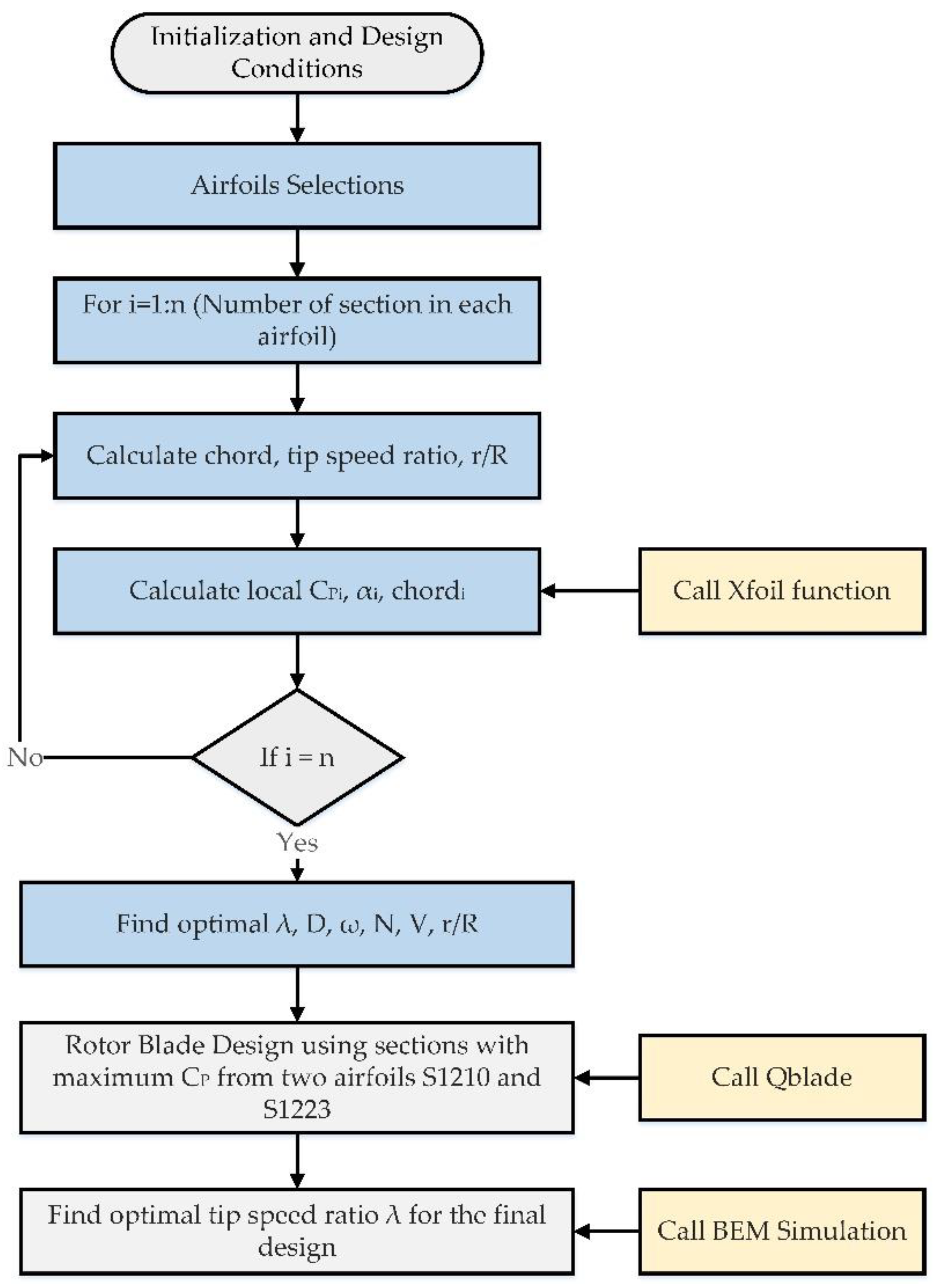
The blade is the main component of the wind turbine, which extracts the energy from the wind, and it contributes 20–25% of the wind turbine’s overall budget [34]. Therefore, it is essential to optimize the design of the wind turbine with a maximum power coefficient under the design conditions. One of the methods to optimize the design of HAWT is the iterative method. The steps of this approach are depicted in Figure 2. The iterative approach aims at analyzing the aerodynamics load based on the Blade Element Momentum (BEM) theory. It assumes that the value of the axial induction coefficient to be zero at the beginning, and it depends on the lift force, drag force, thrust force and tangential force to express the aerodynamic load, and it gives a real understanding of the design problem. In this work, the first objective was to determine the algorithm to be used and the related parameters of tuning to be used during the final solution. Many factors and parameters can affect the design of the blade, and most of these parameters are dependent, which makes the optimization process more complicated. The objective of this work is to design a high-performance, small Horizontal-Axis Wind-Turbine (HAWT) with a Power Coefficient (CP) higher than 40% at an average wind speed of 20 km/h, using multiple stages of optimization and different tools which might help during the optimization process, as well as showing the effect of the different factors on the overall performance of the wind turbine blade. The structural design of the blade will also be taken into consideration to make sure that the blade can withstand the stresses applied to it without breaking or deforming.
The first step in the design process was to determine the design goal, which can be summarized in designing a blade with a maximum length 2 m and operates through wind speeds between 3 m/s and 6 m/s. This means that the blade will have a low Reynolds number due to the small blade surface and relatively low wind speed. The next step is to determine the design parameters which have been discharged in Table 1, and they have been extracted based on Equation (1) to Equation (9). The next steps in the design process can be summarized as follows:
• Initializing Design Conditions
The wind turbine is assumed to operate at a wind speed of 4–7 m/s at a temperature of 15 °C, an air density of 1.1162 kg/m3 with a dynamic viscosity of 1.81 × 10⁻⁵ kg.s/m at 15 °C, the blade length must be less than or equal to 2 m. Therefore, the Reynolds number will be less than or equal to 100,000. The selected number of blades in the designed turbine was three blades, and the tip speed ratio spans from 4 to 8. Finally, the internal to external radius ration was selected between 0.10 to 0.12. Due to the low wind speed and small rotor area, and it was necessary to find a set of airfoils suitable for low Reynolds number applications.
• Selection of the Airfoils
The selection of the airfoils was obtained using the Xfoil tool to evaluate the aerodynamic coefficients of the chosen set of airfoils for the design to find the best pitch-angles for the design wind speed while taking the Blade Element Momentum (BEM) theory into consideration. The selection of the airfoil must consider the need for airfoils, which shows high performance at low wind speed and hence low Reynolds number. After virtually experimenting with multiple airfoil shapes, the chosen set of airfoils for the Design of Experiments include S1210 for the root [35] and S1223 for the tip [36].
• Optimizing the Airfoils Using Xfoil
A MATLAB (MathWorks, Natick, MA, USA) script with four nested for-loops was used to optimize the design of the blade by finding the optimal values of the design parameters. The design parameters that represent the input parameters of the MATLAB program that include the rotor diameter, tip-speed ratio, and internal-external radius ratio. The main goal of the program is to select the airfoil sections which maximize the power coefficient, and the selection of the airfoil sections will be extracted from the selected airfoils which fulfill the design conditions and predefined in the previous step. In each iteration, the MATLAB program returns the power coefficient (CP), which is calculated using the Trapezoidal and Simpson methods. Since the CP differs in each section of the blade, it is necessary to use integration to obtain the overall CP for the entire blade. In addition, the program returns the optimal values of the chord and the optimal AoA for each section of the airfoil. At the end of the iterative process, the program will return the optimal values of the design parameters that are summarized in Table 1.
•  BEM Simulation and Further Optimization Using Qblade
In this part, Qblade (TU Berlin, Berlin, Germany) is used to produce the initial design of the rotor blades. In the first place, the selected airfoils have been imported into Qblade; then, a rotor-blade is designed using those airfoils considering the angles-of-attacks and chords obtained previously. A BEM simulation was also made across the tip-speed ratios 4 to 8 to optimize the tip-speed ratio of the blade, to get the maximum possible power coefficient with this blade. The blades have been investigated at wind speed ranges from 1 m/s to 7 m/s, rotational-speed ranges from 138 rpm to 500 rpm, and Pitch ranges from 0–10 degrees. The chord distribution is optimized further, according to Betz [37]:
C P = 16 9 π R B C L λ 0 1 ( λ 0 r R ) 2 + 4 9
The results of the multi-parameters BEM simulation in QBlade will be presented in the results section. The simulations will present the changes in the generated power by the wind-turbine with the change of wind speed and pitch angles. In addition, the BEM simulation will determine the cut-in and cut-off wind speeds to obtain the maximum possible power coefficient. Finally, the steps of the optimization process of designing the rotor blades have been summarized and depicted in Figure 3.

4. Results and Discussion

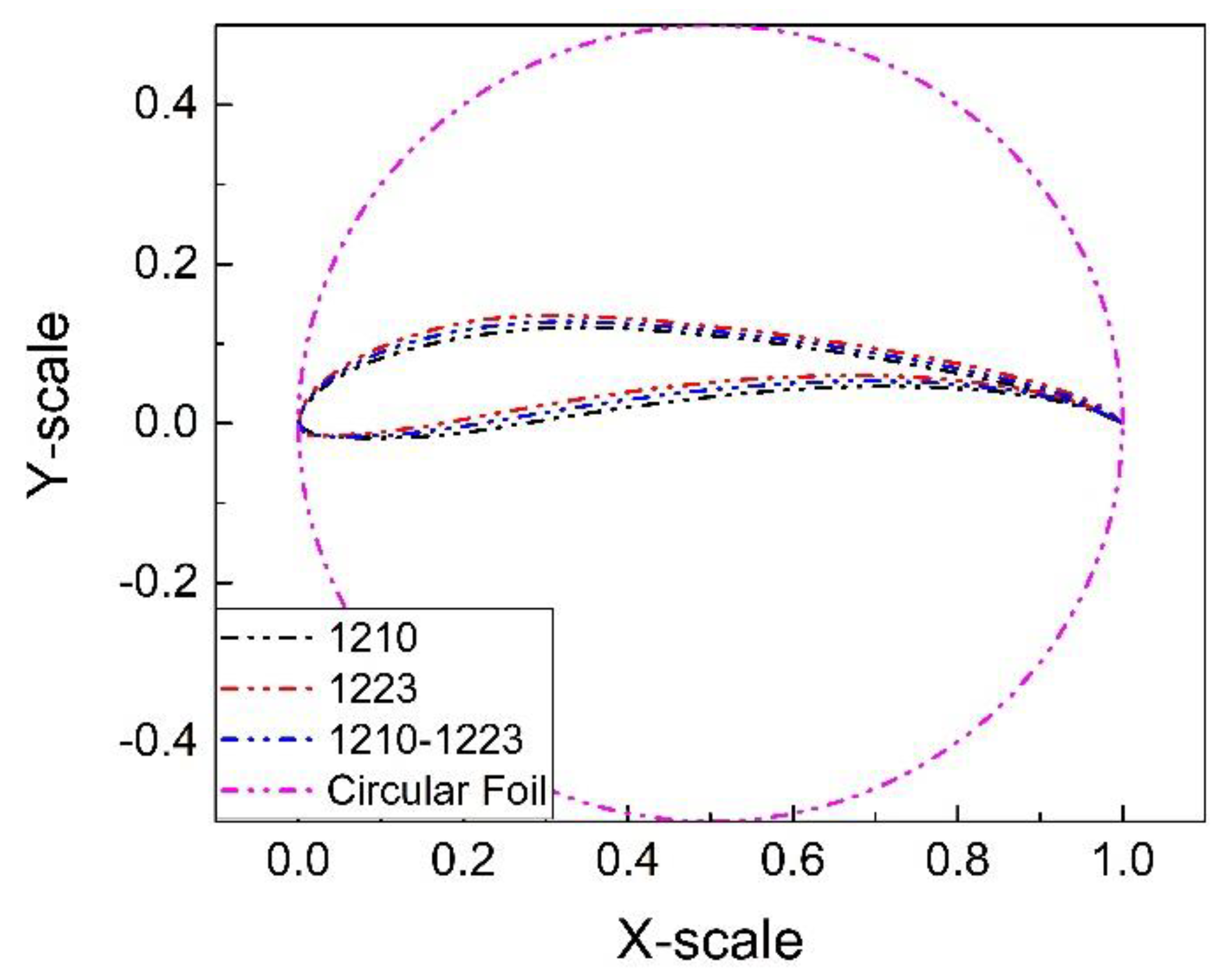
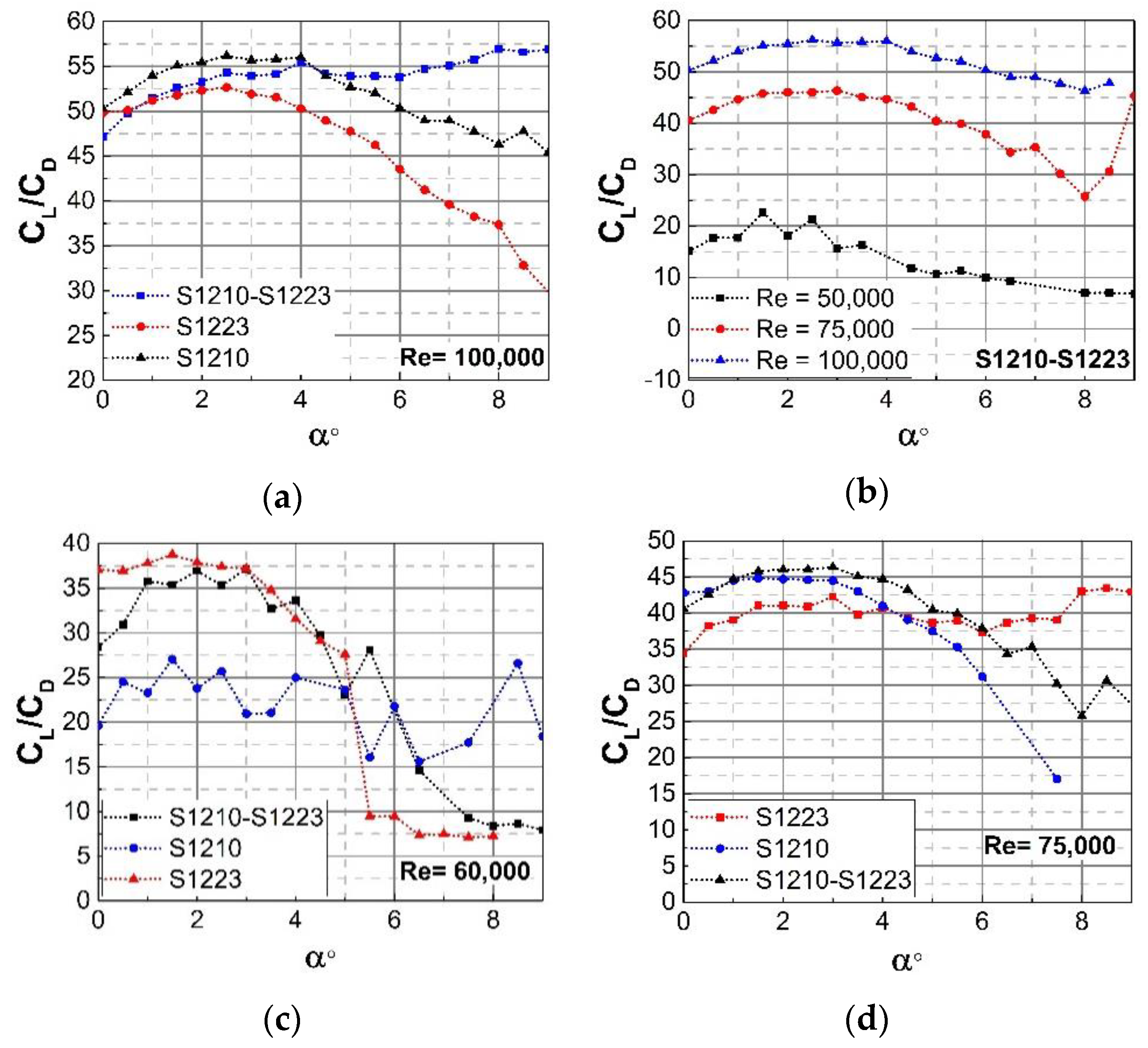
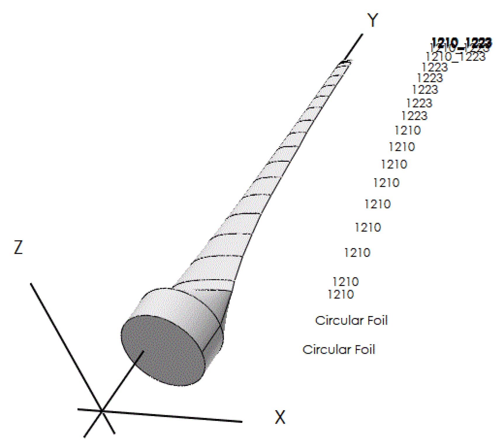
The BEM theory was used for the final design of the blade, which has different cross-sections from root to tip. Furthermore, the BEM theory was used to interpolate two adequate airfoils into one to enhance the performance of the resulted airfoil. Figure 4 depicts the sections of the airfoils S1210, S1223, and the interpolated airfoil section S1210–S1223, which are used in the final blade design. The driving force of a wind turbine is Lift force. Lift force will be perpendicular to the apparent velocity, and it usually increases with AoA. Along with the lift force, an undesirable drag force also increases. This drag force can never be eliminated; therefore, it must be minimized. The best performance a wind turbine can offer is at an angle called optimum attack angle; at this angle, the lift to drag ratio is maximum. In this work, the utilized airfoils have been investigated to determine CL/CD versus the AoA using Qblade software. It is noticed that the interpolated airfoil S1210–S1223 showed higher CL/CD at different Reynolds numbers with the range of AoA shown in Figure 5. At a Reynolds number of 100,000, the interpolated airfoil showed a higher CL⁄CD ratio than S1210 and S1223 for AoA lower than 4.2 degrees. In addition, the interpolated airfoil showed a higher CL⁄CD ratio for the whole range of AoA when the Reynolds number is set at 75,000. The impact of the Reynolds number on the CL⁄CD ratio of the S1210–S1223 airfoil is depicted in Figure 5b. It is seen that the CL⁄CD ratio is higher in the case of selecting the highest possible Reynolds number at low wind speed. Accordingly, the Reynolds number was settled 100,000 during the simulation, and it was determined that an interpolated blade between the profiles ‘S1210′, ‘S1223′ will tick all the criteria boxes in terms of high CL⁄CD ratio on low Reynolds numbers, and gives relatively high performance given the limitations.
It is worth mentioning that simulation settings have been set at an air density of 1.1162 kg/m3 and an air viscosity of 1.81 × 10⁻⁵ kg.s/m, 40 blade elements, 100 iterations, maximum 0.001 for convergence, and a relaxation factor of 0.3. In addition, the analysis conditions were set at wind range at a speed from 1 m/s to 7 m/s, rotor range in rotational speed from 138 rpm to 500 rpm, and a pitch angle from 0° to 10°. The length of a blade is a significant factor affecting the power extracted from the wind, looking back at Equation (7), the relation between the length of the blade (R) and power (Pr) is squared.
Therefore, the blade length has been set at 2 m during the optimization process to maximize the generated power since this value represents the maximum permissible length in the proposed study. The optimal values of the design parameters have been discharged in Table 2. The values of these parameters will be used to produce the blade using the Qblade. The Qblade was used to further smoothen the blade around the transition areas (from one airfoil to another), as depicted in Figure 6. This blade is considered as the final design. After improving the design of the final blade using the Qblade as mentioned previously and implementing the BEM simulation, the CP of the blade was increased to almost 0.45, which is relatively high considering the size and the speed of the wind. Figure 7 depicts the impact of the design parameters on the power coefficient which are represented by the rotor diameter, tip speed ratio, and the internal to external radius ratio. In Figure 7a, it is noticed that the CP value is slightly increased with increasing the rotor diameter (D) at the same tip speed ratio (λ). On the other hand, the increase of tip speed ratio will yield in increasing CP for the same rotor diameter, which is true if the length of the rotor blade is greater than 3 m as depicted in Figure 7b. In addition, it was observed that the CP value decreases with an increase in the internal to external radius ratio (rR) at the same tip speed ratio as shown in Figure 7c. The maximum CP is obtained corresponding to D = 4 m, λ = 6, and rR = 0.1 m. In Figure 8a, it was noticed that the power generated can increase to almost double just by increasing the velocity by 2 m/s, the rated power at 5.5 m/s will be around 650 Watts. In Figure 8b, the results showed that CP is increasing proportionally with increased rotor diameter. In Figure 8c, since the design was based on an optimal average wind speed of 5.5 m/s, the maximum CP of 0.445 was obtained around that value. When the speed diverges from the design wind speed, it is normal for the CP to drop.
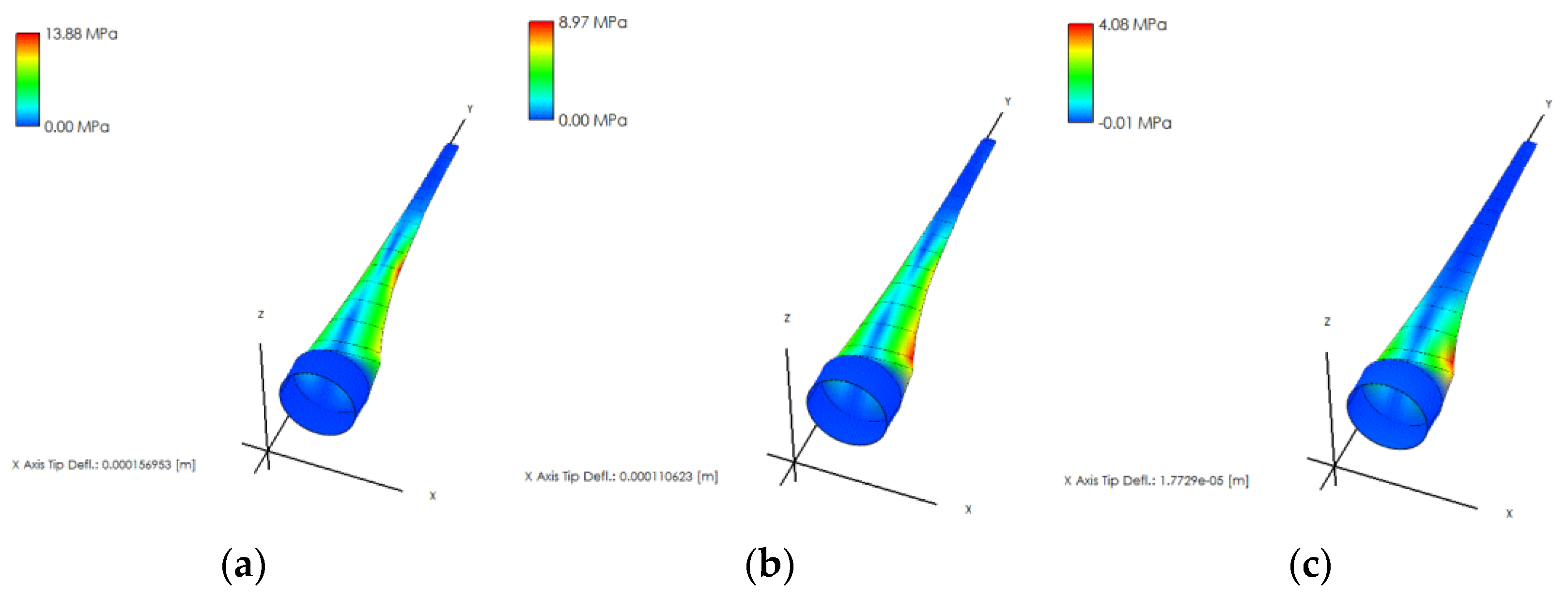
The mass of the blade is dependent on the thickness of the spar cap that can be minimized at different cross-sections to comply with the permissible level of strain. In addition, the selection of the shell material and the internal material of the blade has a substantial impact on the mass of the blade. The thickness of the shell layer and the internal layer was 9% the length of the local chord of the blade section. In order to investigate the performance of the designed blade, it was possible to perform a stress-analysis simulation using QBlade to show the stresses on the blade corresponding to the loads applied by the wind on it under the operating conditions of the wind turbine. It was necessary to identify the internal structure of the blade, as well as the shell material and internal material, and the mass of the blade was calculated using the software. Therefore, the internal structure of the blade was hollow with spar, and the utilized internal material is a Ti foam with a compressive-yield strength of 256 MPa. The shell material is made of Aluminum with a compressive-yield strength of 310 MPa. The Von-Mises stresses acting on the blade under the operating conditions have been determined, and the stress-distribution model is showing the critical sections of the blade was created.
The stress analysis was performed using the Qblade at different rotational speeds to show the behavior of the designed blades in loading conditions. Figure 9 shows the maximum stress on the designed blade to be 13.88 MPa at a rotational speed of 100 rpm, which is far less than the yield strength of Aluminum (310 MPa), the deflection on the z-axis is (0.00355756 m) and on the x-axis (0.000156953 m). Furthermore, the stress analysis that was performed on the designed blade has been investigated at 235 rpm and 500 rpm, which represents that the maximum rotational speed was set during the design process. The results of the stress analysis at different rotational speeds are depicted in Figure 8.

5. Validation of the Proposed Approach

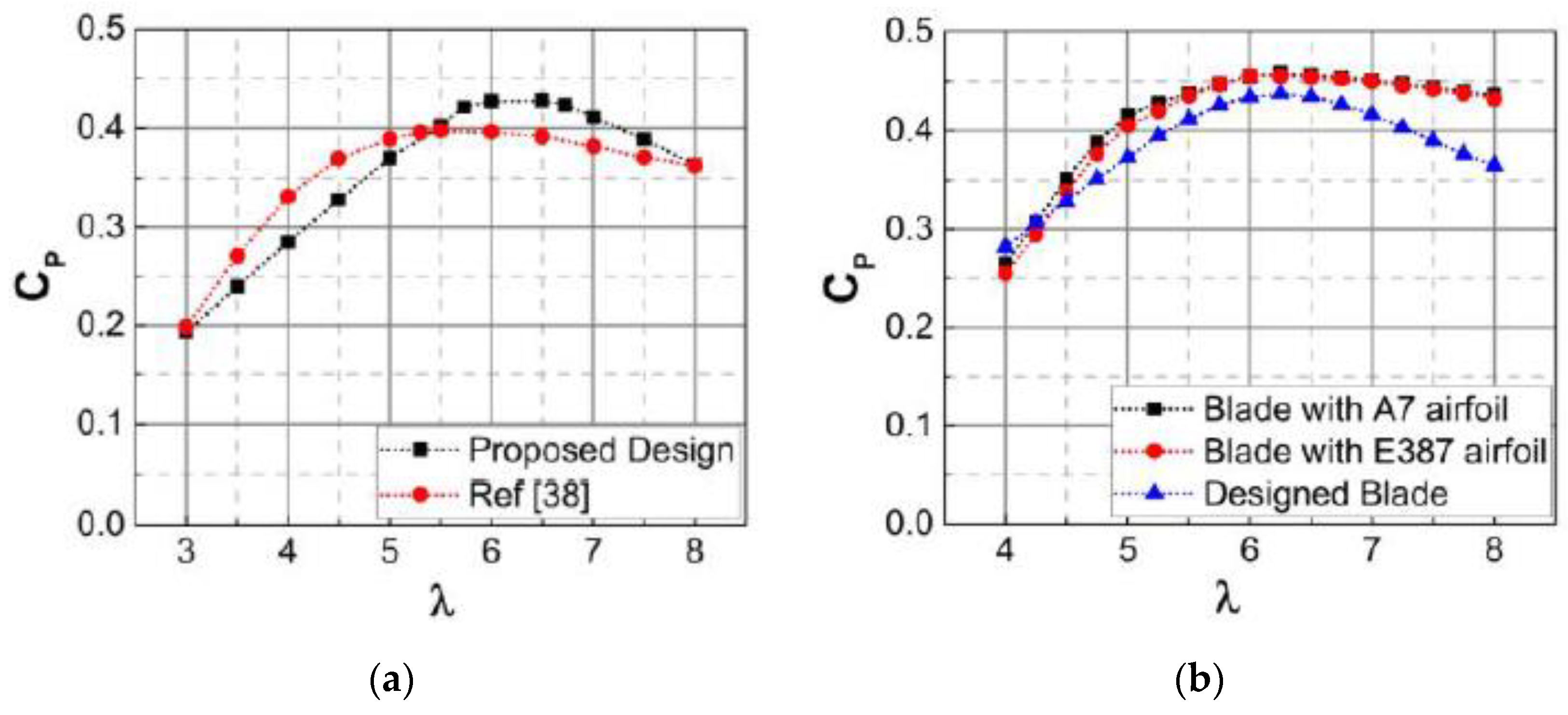
For the sake of validating the proposed approach in designing and optimizing a small wind turbine blade, the results have been compared with experimental results obtained in previous works. The comparison is valid due to adopting the same test conditions during the simulation. The first comparison considered the operation of the designed turbine at a wind speed of 12 m/s with Reynolds number of 100,000, and the radius of the blade was less than 2 m as in [38]. Figure 10a depicts the simulation results in terms of the power coefficient of the designed blade at different tip speed ratios in comparison with experimental results in [38]. The simulation’s settings in Qblade have been updated to establish another comparison in which the designed turbine will operate at rated wind speed of 10.5 m/s with a cut-in speed of 4 m/s and cut out speed of 15 m/s at rated rotating speed of 250 rpm as in [39].
The designed blade was scaled to have a length of 1.85 m and the Reynolds number was selected at 100,000. The result of the comparison is depicted in Figure 10b. The results of the blades with A7 and E185 airfoils have been compared with designed blade, and the results of the comparison showed a good matching between the behavior of the designed blade and the other blades at the same test conditions that validate the design approach. In order to estimate the percentage of matching, the Root Mean Squared Error (RMSE) has been used to calculate the error between the simulation and the experimental results. The results of the RMSE calculations have been discharged in Table 3.

6. Conclusions

The objective of this work is to design and optimize a Horizontal-Axis Wind-Turbine blade for relatively low Reynolds’ numbers and higher power coefficient. The design of the blade is achieved by employing BEM theory, and optimization is performed using the software QBlade. A MATLAB script is utilized and implemented to find the power coefficient for the selected input parameters. The MATLAB script is designed to obtain up to four factors at a time to implement the design of experiments. The numerical results reveal that the interpolated airfoils that are formed from S1210 and S1223 airfoils are the selections, as they show good results under the selected operating conditions. The rotor-design was also obtained, which consists of 3-blades with a diameter of 4 m, a hub of 20 cm radius, a tip-speed ratio of 6.5, and can generate around 650 W with a Power coefficient of 0.445 at a wind-speed of 5.5 m/s, reaching a power of 1.18 kW and a power coefficient of 0.40 at a wind-speed of 7 m/s. The numerical results are compared with the available data and are found in good agreement.

Author Contributions

Conceptualization, H.M. and W.A.-K.; methodology, W.A.-K. and H.M. Software, H.M. and W.A.-K.; validation, H.M.; W.A.-K.; and W.K.; formal analysis, H.M.; investigation, W.A.-K. and W.K.; resources, H.M. and W.A.-K.; data curation, H.M.; writing-H.M., W.A.-K., and W.A.K. Draft preparation, H.M., W.A.-K.; writing—review and editing, W.A.-K. and H.M.; visualization, H.M.; supervision, H.M. and W.A.-K.; project administration, H.M. and W.A.-K. All authors have read and agreed to the published version of the manuscript.

Funding

This research received no external funding.

Conflicts of Interest

The authors declare no conflict of interest.

Abbreviations

ρDensity of air (1.22 kg/m3)
NNumber of blades
DBlade Diameter (m)
PMechanical Power (W)
VUpstream wind-speed (m/s)
CPPower coefficient
CQTorque coefficient
cCross section Area at radius r (m2)
λ, λ0tip-speed ratio, optimum
FLLift force (N)
FDDrag force (N)
CLLift coefficient
CDDrag coefficient
FTTangential force (N)
τrTorque per unit-length (N)
VrelRelative wind speed (m/s)
RRadius of the rotor (m)
ΦAngle of relative wind (deg)
βPitch angle (deg)
Rotational Speed (rad/s)
AArea (m2)
RrExternal radius to internal radius ratio (r / R)
VAverage wind speed (m/s)
aAxial Induction factor
a’Radial Induction factor
ClineChord line
AoAAngle of Attack
rInternal radius (Distance between the axis of rotation and the blade section) (m)
ReReynolds number

References

  1. Hau, E. Wind Turbines: Fundamentals, Technologies, Application, Economics; Springer Science & Business Media: Berlin, Germany, 2013. [Google Scholar]
  2. Carbon, T. Small-Scale Wind Energy-Policy Insights and Practical Guidance; Carbon Trust: London, UK, 2008. [Google Scholar]
  3. World Wind Energy Association. Wind Power Capacity Reaches 539 GW, 52.6 GW Added in 2017. Available online: https://wwindea.org/blog/2018/02/12/2017-statistics/ (accessed on 20 February 2018).
  4. Sessarego, M.; Wood, D. Multi-dimensional optimization of small wind turbine blades. Renew. Wind Water Sol. 2015, 2, 9. [Google Scholar] [CrossRef] [Green Version]
  5. Al-Abadi, A.; Özgür, E.; Horst, W.; Antonio, D. A design and optimization method for matching the torque of the wind turbines. J. Renew. Sustain. Energy 2015, 7, 1–11. [Google Scholar] [CrossRef]
  6. Hassanzadeh, A.; Hassanabad, A.H.; Dadvand, A. Aerodynamic shape optimization and analysis of small wind turbine blades employing the Viterna approach for post-stall region. Alex. Eng. J. 2016, 55, 2035–2043. [Google Scholar] [CrossRef] [Green Version]
  7. El-Mouhsine, S.; Oukassou, K.; Ichenial, M.M.; Kharbouch, B.; Hajraoui, A. Aerodynamics and structural analysis of wind turbine blade. Procedia Manuf. 2018, 22, 747–756. [Google Scholar] [CrossRef]
  8. Lanzafame, R.; Mauro, S.; Messina, M. HAWT Design and Performance Evaluation: Improving the BEM Theory Mathematical Models. Energy Procedia 2015, 82, 172–179. [Google Scholar] [CrossRef] [Green Version]
  9. Ribeiro, A.F.P.; Awruch, A.M.; Gomes, H.M. An airfoil optimization technique for wind turbines. Appl. Math. Model. 2012, 36, 4898–4907. [Google Scholar] [CrossRef]
  10. Nada, A.A.; Al-Shahrani, A.S. Shape Optimization of Low Speed Wind Turbine Blades using Flexible Multibody Approach. Energy Procedia 2017, 134, 577–587. [Google Scholar] [CrossRef]
  11. Jeong, J.; Park, K.; Jun, S. Design optimization of a wind turbine blade to reduce the fluctuating unsteady aerodynamic load in turbulent wind. J. Mech. Sci. Technol. 2012, 26, 827. [Google Scholar] [CrossRef]
  12. Erfort, G.; Von Backstrom, T.W.; Venter, G. Numerical optimization of a small-scale wind turbine through the use of surrogate modelling. J. Energy S. Afr. 2017, 28, 79–91. [Google Scholar] [CrossRef] [Green Version]
  13. Mohammadi, M.; Mohammadi, A.; Mohammadi, M.; Minaei, H.N. Optimization of Small-Scale Wind Turbine Blades for Low Speed Conditions. JOCET 2016, 4, 140–143. [Google Scholar] [CrossRef] [Green Version]
  14. Tenguria, N.; Mittal, N.D.; Ahmed, S. Review on Horizontal Axis Wind Turbine Rotor Design and Optimization. Trends Appl. Sci. Res. 2011, 6, 309–344. [Google Scholar] [CrossRef]
  15. Vivek, C.M.; Gopikrishnan, P.; Murugesh, R.; Mohamed, R.R. A Review on Vertical and Horizontal Axis Wind Turbine. IJRET 2017, 4, 247–250. [Google Scholar]
  16. Jureczko, M.; Pawlak, M.; Mezyk, A. Optimization of wind turbine blades. J. Mater. Process. Technol. 2005, 167, 463–471. [Google Scholar] [CrossRef]
  17. Benini, E.; Toffolo, A. Optimal Design of Horizontal-Axis Wind Turbines Using Blade-Element Theory and Evolutionary Computation. J. Sol. Energy Eng. 2002, 124, 357–363. [Google Scholar] [CrossRef]
  18. Chehouri, A.; Younes, R.; Ilinca, A.; Perron, J. Wind Turbine Design: Multi-Objective Optimization. arXiv 2016, arXiv:1610.00975. [Google Scholar]
  19. Thumthae, C. Optimum Blade Profiles for a Variable-Speed Wind Turbine in Low Wind Area. Energy Procedia 2015, 75, 651–657. [Google Scholar] [CrossRef] [Green Version]
  20. Tang, X.; Huang, X.; Peng, R.; Liu, X. A Direct Approach of Design Optimization for Small Horizontal Axis Wind Turbine Blades. Procedia CIRP 2015, 36, 12–16. [Google Scholar] [CrossRef] [Green Version]
  21. Lin, Y.T.; Chiu, P.H.; Huang, C.C. An experimental and numerical investigation on the power performance of 150 kW horizontal axis wind turbine. Renew. Energy 2017, 113, 85–93. [Google Scholar] [CrossRef]
  22. Pourrajabian, A.; Afshar, P.A.N.; Ahmadizadeh, M.; Wood, D. Aero-structural design and optimization of a small wind turbine blade. Renew. Energy 2016, 87, 837–848. [Google Scholar] [CrossRef]
  23. Tahir, A.; Elgabaili, M.; Rajab, Z.; Buaossa, N.; Khalil, A.; Mohamed, F. Optimization of small wind turbine blades using improved blade element momentum theory. Wind Eng. 2019, 43, 1–12. [Google Scholar] [CrossRef]
  24. Battisti, L.; Benini, E.; Brighenti, A.; Dell’Anna, S.; Castelli, M.R. Small wind turbine effectiveness in the urban environment. Renew. Energy 2018, 129, 102–113. [Google Scholar] [CrossRef]
  25. Karthikeyan, N.; Murugavel, K.K.; Kumar, S.A.; Rajakumar, S. Review of aerodynamic developments on small horizontal axis wind turbine blade. Renew. Sustain. Energy Rev. 2015, 42, 801–822. [Google Scholar] [CrossRef]
  26. Singh, R.K.; Ahmed, M.R. Blade design and performance testing of a small wind turbine rotor for low wind speed applications. Renew. Energy 2013, 50, 812–819. [Google Scholar] [CrossRef]
  27. Song, D.; Fan, X.; Yang, J.; Liu, A.; Chen, S.; Joo, Y.H. Power extraction efficiency optimization of horizontal-axis wind turbines through optimizing control parameters of yaw control systems using an intelligent method. Appl. Energy 2018, 224, 267–279. [Google Scholar] [CrossRef]
  28. Sarkar, M.; Julai, S.; Wen Tong, C.; Toha, S.F. Effectiveness of Nature-Inspired Algorithms using ANFIS for Blade Design Optimization and Wind Turbine Efficiency. Symmetry 2019, 11, 456. [Google Scholar] [CrossRef] [Green Version]
  29. Bianchi, F.D.; De Battista, H.; Mantz, R.J. Wind Turbine Control Systems: Principles, Modeling and Gain Scheduling Design; Springer Science & Business Media: Berlin, Germany, 2006. [Google Scholar]
  30. Ingram, G. Wind Turbine Blade Analysis Using the Blade Element Momentum Method; Version 1.1.; Durham University: Durham, NC, USA, 2011. [Google Scholar]
  31. Sriti, M. Improved blade element momentum theory (BEM) for predicting the aerodynamic performances of horizontal Axis wind turbine blade (HAWT). Tech. Mech. Sci. J. Fundam. Appl. Eng. Mech. 2018, 38, 191–202. [Google Scholar]
  32. Kavari, G.; Tahani, M.; Mirhosseini, M. Wind shear effect on aerodynamic performance and energy production of horizontal axis wind turbines with developing blade element momentum theory. J. Clean. Prod. 2019, 219, 368–376. [Google Scholar] [CrossRef]
  33. Dehouck, V.; Lateb, M.; Sacheau, J.; Fellouah, H. Application of the Blade Element Momentum Theory to Design Horizontal Axis Wind Turbine Blades. J. Sol. Energy Eng. 2018, 140, 014501. [Google Scholar] [CrossRef]
  34. Fingersh, L.; Hand, M.; Laxson, A. Wind Turbine Design Cost and Scaling Model; No. NREL/TP-500-40566; National Renewable Energy Lab. (NREL): Golden, CO, USA, 2006.
  35. Selig, M.S.; Guglielmo, J.J.; Broeren, P.; Giguere, P. Summary of Low-Speed Airfoil Data; Volume 1; SoarTech Publications: Virginia Beach, VA, USA, 1995. [Google Scholar]
  36. Selig, M.S.; McGranahan, B.D. Wind Tunnel Aerodynamic Tests of Six Airfoils for Use on Small Wind Turbines Period of Performance; NREL/SR-500-34515; Office of Scientific and Technical Information: Oak Ridge, TN, USA, 2003; p. 1188.
  37. Probst, O.; Martínez, J.; Elizondo, J.; Monroy, O. Small Wind Turbine Technology Wind Turbines; Al-Bahadly, I., Ed.; InTech: Rijejka, Croatia, 2011; ISBN 978-953-307-221-0. [Google Scholar] [CrossRef]
  38. Bai, C.J.; Wang, W.C.; Chen, P.W.; Chong, W.T. System integration of the horizontal-axis wind turbine: The design of turbine blades with an axial-flux permanent magnet generator. Energies 2014, 7, 7773–7793. [Google Scholar] [CrossRef] [Green Version]
  39. Shen, X.; Avital, E.; Paul, G.; Rezaienia, M.A.; Wen, P.; Korakianitis, T. Experimental study of surface curvature effects on aerodynamic performance of a low Reynolds number airfoil for use in small wind turbines. J. Renew. Sustain. Energy 2016, 8, 053303. [Google Scholar] [CrossRef]
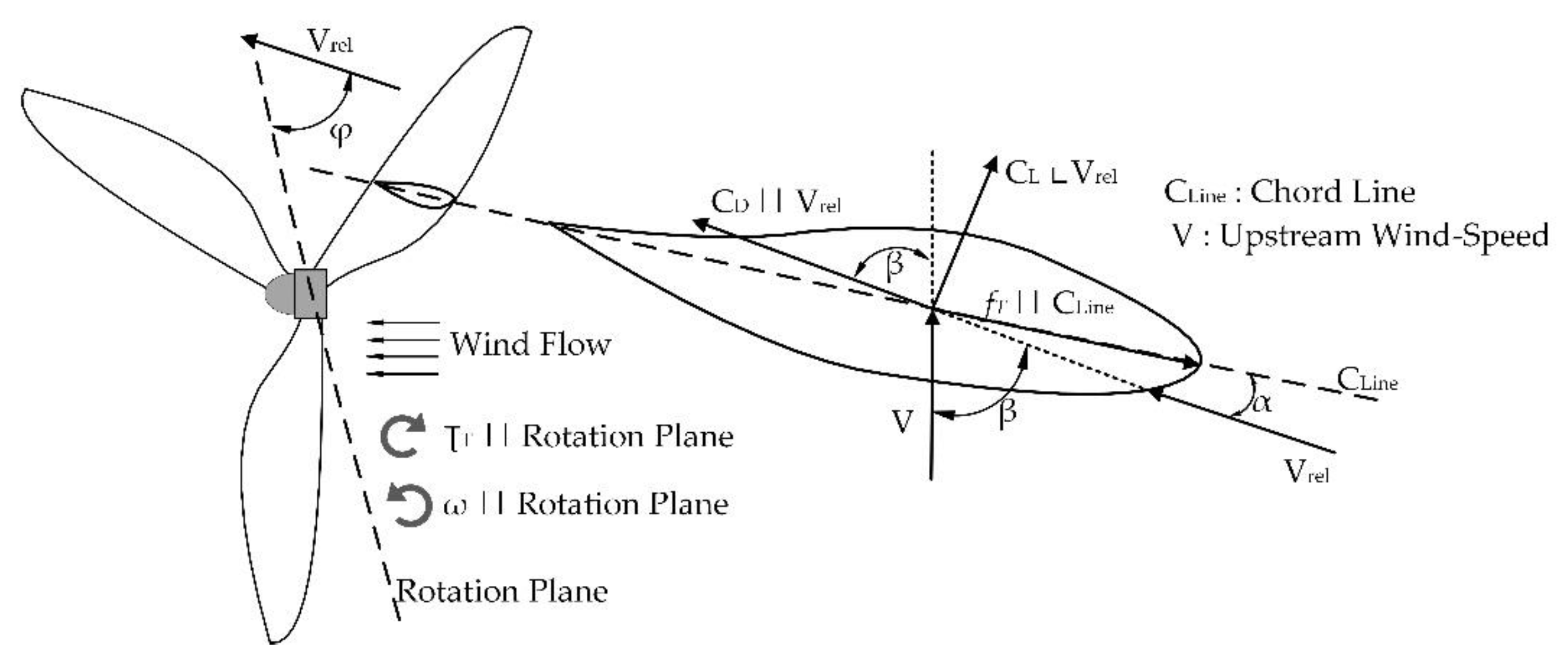
Figure 1. Blade sectional aerodynamic angles and forces coefficients, where || indicates parallel relation and ∟indicates perpendicular relation.
Symmetry 12 00018 g001
Figure 2. Iterative method procedures.
Symmetry 12 00018 g002
Figure 3. Rotor blades design and optimization procedures.
Symmetry 12 00018 g003
Figure 4. The sections of the airfoils S1210, S1223, and the interpolated airfoil section S1210–S1223.
Symmetry 12 00018 g004
Figure 5. CL/CD vs. AoA for (a) S1210, S1223, S1210–S1223 airfoils with Re = 100,000, (b) S1210–S1223 airfoils with Re = 100,000, Re = 75,000, Re = 50,000, (c) S1210, S1223, S1210–S1223 airfoils with Re = 60,000, (d) S1210, S1223, S1210–S1223 airfoils with Re = 75,000.
Symmetry 12 00018 g005
Figure 6. Resultant blade from XFOIL and MATLAB with Airfoil sections along the length of the blade.
Symmetry 12 00018 g006
Figure 7. The impact of design parameters on CP (a) D vs. CP at rR = 0.10 m at various tip speed ratios; (b) CP vs. λ at rR = 0.10 m at various blade diameters; (c) CP vs. rR at D = 3 m at various tip speed ratios.
Symmetry 12 00018 g007
Figure 8. (a) Power vs. Wind Speed; (b) CP vs. Wind speed; (c) CP vs. λ.
Symmetry 12 00018 g008
Figure 9. Stress analysis of the blade.at 100 rpm (a), at 235 rpm (b), at 500 rpm (c).
Symmetry 12 00018 g009
Figure 10. A comparison between the proposed approach and experimental works in [38,39].
Symmetry 12 00018 g010
Table 1. Output parameters of the optimization process.
Number of Variables and Output ParametersSymbolDescription
1 N Number of Blades
2 λ Tip speed ratio (unitless)
3 D Rotor diameter (m)
4 ω Angular velocity (rad/s)
5 a Induction factor (unitless)
6 V Wind speed (m/s)
7 C p Power coefficient (%)
8 P o w e r Watts
9 r /RInternal-to-external radius ratio
Table 2. Optimal values of design variables.
λNo. of BladesD (m)⍵ (rad/s)aV (m/s)r/RCP(trap)CP(sim)
63416.50.2755.50.10.3918760.405566
Table 3. RMSE between the results of the designed blade in simulation and experimental results in [38,39] under similar design conditions.
Designed Blade vs. Blade with Blade in [38]Designed Blade vs. Blade with A7 Airfoil [39]Designed Blade vs. Blade with E387 Airfoil [39]
RMSE0.03210.03700.0340