Article

Constitutive Model of Stress-Dependent Seepage in Columnar Jointed Rock Mass

1
Key Laboratory of Ministry of Education for Geomechanics and Embankment Engineering, Hohai University, Nanjing 210098, China
2
Jiangsu Research Center for Geotechnical Engineering Technology, Hohai University, Nanjing 210098, China
*
Author to whom correspondence should be addressed.
Symmetry 2020, 12(1), 160; https://doi.org/10.3390/sym12010160
Submission received: 12 December 2019 / Revised: 7 January 2020 / Accepted: 9 January 2020 / Published: 13 January 2020

Abstract

:
Columnar jointed rock mass (CJRM) is a highly symmetrical natural fractured structure. As the rock mass of the dam foundation of the Baihetan Hydropower Station, the study of its permeability anisotropy is of great significance to engineering safety. Based on the theory of composite mechanics and Goodman’s joint superposition principle, the constitutive model of joints of CJRM is derived according to the Quadrangular prism, the Pentagonal prism and the Hexagonal prism model; combined with Singh’s research results on intermittent joint stress concentration, considering column deflection angles, the joint constitutive model of CJRM in three-dimensional space is established. For the CJRM in the Baihetan dam site area, the Quadrangular prism, the Pentagonal prism and the Hexagonal prism constitutive models were used to calculate the permeability coefficients of CJRM under different deflection angles. The permeability anisotropy characteristics of the three models were compared and verified by numerical simulation results. The results show that the calculation results of the Pentagonal prism model are in good agreement with the numerical simulation results. The variation of permeability coefficient under different confining pressures is compared, and the relationship between permeability coefficient and confining pressure is obtained, which accords with the negative exponential function and conforms to the general rule of joint seepage.

1. Introduction

A columnar jointed rock mass (CJRM) is formed by cutting the intact rock from different structural planes, and has long-term complex geological evolution and possesses strong symmetry [1,2,3]. A typical CJRM is shown in Figure 1. With the construction of water conservancy projects in southwestern China, engineering problems involving CJRM dam foundation materials are increasing [4,5]. Among them, the Baihetan Hydropower Project in Jinsha River is the most typical, and the columnar jointed basalt in the dam site is widely developed, covering an area of about 5 × 10⁴ square kilometers. Therefore, the study of CJRM mechanics and seepage characteristics is essential for engineering design and safe construction.
The anisotropy of a jointed rock mass is mainly controlled by the intact rock mass and the joint [6,7,8]. For intact rock masses, the permeability coefficient is extremely weak, and the flow of water in it is negligible. Therefore, the permeability characteristics of the jointed rock mass mainly depend on the joint features [9,10]. Because the elastic modulus of the joint rock mass is much smaller than that of the intact rock mass, the difference between the two deformations under stress reflects the deformation of the joint, which directly affects the water passing capacity and the seepage characteristics of the jointed rock mass. Therefore, in order to fully understand the joint permeability characteristics of a jointed rock mass, it is of great significance to study the joint deformation ability of the jointed rock mass under stress.
The theoretical analytical method provides a convenient and fast way of studying the deformation characteristics of jointed rock masses. Singh [11,12] and Gerrard [13,14] studied the constitutive relations of one, two and three sets of jointed rock masses using theoretical methods. Yan [15] and Meng [16] developed the equivalent model compound analytical method, and derived a constitutive model of the regular quadrilateral and regular Hexagonal CJRM.
With respect to stress-seepage coupling, Zou [17] obtained a stress-dependent quadrilateral columnar joint seepage model through a triaxial seepage test; Xiong [18] analyzed the influence of deflection angle on the permeability coefficient by 3DEC numerical simulation method; white cement was used as the joint medium, and the empirical formula of the permeability coefficient of the Hexagonal columnar joint was obtained using a triaxial seepage test [19,20]. It can be seen that the current research on the seepage characteristics of columnar joints is mostly based on physical model tests, so that the permeability coefficient is solved by empirical formulas, and there is no relevant theoretical research. Field investigations have found that the columns commonly found in the actual geological environment are irregular Quadrangular prisms, Pentagonal prisms and Hexagonal prisms. Table 1 reflects the natural structural features of CJRM; from this, we can see that the quadrilateral, pentagon and hexagon account for more than 90%, and the pentagon accounts for a large proportion. Therefore, carrying out related research on the regular Quadrangular prism and Hexagonal prism models only is a great limitation. It is necessary to fully consider the influence of different cross-section shapes on the seepage characteristics of CJRM.
In this paper, a stress-dependent columnar joint seepage model is established. The Pentagonal column constitutive model proposed by Que [21] is introduced simultaneously with the Quadrangular prism and the Hexagonal column model. Based on the theory of composite mechanics and Goodman’s joint superposition principle, the constitutive model of joints of CJRM is derived on the basis of the Quadrangular prism, the Pentagonal prism and the Hexagonal prism model in combination with Singh’s research results on intermittent joint stress concentration and considering column deflection angle. The joint constitutive model of CJRM in three-dimensional space is established, and finally, the joint mechanical aperture is converted into the equivalent hydraulic aperture, and the permeability coefficient is calculated. The variation of permeability coefficient under different confining pressures is compared, and the relationship between permeability coefficient and confining pressure is obtained, which corresponds to the negative exponential function and conforms to the general rule of joint seepage. Three constitutive models were applied to the CJRM of Baihetan. The variation of permeability coefficient under different deflection angles of the columns was analyzed and compared, and the calculated results were compared with the numerical simulation results. The results show that the constitutive relation of the Pentagonal prism model has good applicability and can provide a reference for the permeability analysis of large-scale water conservancy and hydropower projects.

2. Establishment of Seepage Model for Stress-Dependent Fractured Rock Mass

2.1. Seepage Model

The seepage theory of rock mass originated from the study of single-fracture seepage in rock. The Soviet scholar Lomize [22] and the French scholar Louis [23] carried out the first smooth parallel plate tests and established the famous cubic law:
q = g b 3 12 μ J f = K f b J f
where q is the unit width flow, g is gravity, Jf is the hydraulic gradient parallel to the structural planes, b is the aperture, and μ is dynamic viscosity of fluid. Correspondingly, the permeability coefficient of a smooth joint can be expressed as Kf = gb2/12μ.
The cubic law is applicable to smooth fractures, but the natural fracture surface has rough characteristics; therefore, the equivalent hydraulic aperture bh is needed in the calculation. Lomize [24] and Louis [25] established the following expressions using the fracture surface roughness correction coefficient method:
b h = β b 3 C , C L omize = 1 + 6.0 ( e b ) 1.5 , C L ouis = 1 + 8.8 ( e b ) 1.5
where β is the ratio of the area of the joint in the fracture to the total area; CLomize, CLouis are the correction coefficient of the fracture surface roughness and e is the absolute height of the protrusion of the fracture surface.
Barton [26] and Bandis [27] established the expression of the equivalent hydraulic aperture of the fracture based on the mechanical aperture, which takes the joint roughness coefficient (JRC) as a parameter; the formula can be expressed as:
b h = b 2 J R C 2.5 = δ max 2 J R C 2.5 ( 1 + σ n δ max 2 K n 0 ) 2
where δmax2 is the maximum fracture displacement, and σn’ is the effective normal stress. Kn0 is initial normal stiffness when normal stress is zero.
Zou [17] used JRC as a measurable parameter when constructing the stress-dependent joint rock mass seepage model, and calculated the permeability coefficient considering the joint aperture change under stress. Therefore, when calculating the stress-dependent permeability coefficient of fractured rock mass, the equivalent hydraulic aperture can be calculated by calculating the mechanical opening of fracture under complex stress.

2.2. Stress-Dependent Seepage Model

In actual rock engineering, a single fracture is not only affected by normal stress σ1, but also by lateral stress σ2 and σ3 in two directions parallel to the fracture when calculating the permeability coefficient; it is also subject to water pressure P, as shown in Figure 2.
When Louis [23] described the influence of stress on fracture deformation, a large number of experiments showed that the relationship between fracture deformation and stress was a negative exponential function. Supposing the maximum aperture at zero normal stress of the fracture is b0, the normal stiffness of the crack is kn, the deformation of the crack under the normal stress can be expressed as follows:
u = b 0 [ 1 exp ( σ n k n ) ]
According to the fracture surface roughness correction coefficient method, the corresponding permeability coefficient Kf can be expressed as:
K f = g b h 12 μ = g 12 μ J R C 2.5 ( b 0 exp ( 2 σ 1 K n ) ) 2
Equation (4) establishes the stress-dependent seepage formula based on the negative exponential function of the single jointed rock mass. The factors affecting the permeability coefficient Kf of the jointed rock mass are only the effective normal stress σn’ and JRC, so the fracture permeability coefficient can be expressed as a function of the mechanical aperture, assuming that the fracture parameters are constant. When studying the seepage characteristics of CJRM, since the joint is in the form of a joint group, the results obtained by the superposition method of Formula (4) contains a large error, and the calculation of the permeability coefficient of Formula (4) is completely based on the physical test experience, which cannot accurately react to the permeability characteristics of columnar jointed rock masses. Therefore, it is necessary to propose a method for accurately calculating the analytical solution of the joint opening. In this article, which is based on the theory of composite mechanics and Goodman’s joint superposition principle, the constitutive model of joints of CJRM is derived on the basis of the Quadrangular prism, the Pentagonal prism and the Hexagonal prism model. Through these three models, the permeability characteristics of the columnar jointed rock mass can be reflected.

3. Establishment of Seepage Model for Stress-Dependent Fractured Rock Mass

To describe the constitutive model, three premises need to be initially confirmed [28,29]:
Anisotropy of the CJRM is predominantly controlled by structural planes.
CJRM can be treated as an elastic, homogeneous and anisotropic object.
The seepage pressure acts on the outside of the rock mass as an external load, and the JRC of the fracture does not change with the aperture of the fracture.

3.1. Stress-Dependent Seepage Model

Columnar joints can be regarded as a complete rock mass cut by multiple sets of joints. The cross-section shapes of CJRM are primarily irregular Quadrangular, Pentagonal, and Hexagonal in nature [30]. When establishing the corresponding constitutive model, Quadrangular and Hexagonal prism models are easier to establish due to their symmetry. The Pentagonal prism model is more complex due to the introduction of variable angle θ, where θ is the angle between the top and the bottom parallel directions, which can be adjusted according to the actual situation on site, reflecting the flexibility of this model. Three generalized models of the CJRM are shown in Figure 3:
Due to weathering and sedimentation, the physical mechanics and seepage characteristics of the internal filling materials of the joints are quite different compared with the intact rock mass. When subjected to external forces, the total strain {εs} produced by the jointed rock mass comprises joint strain {εj} and intact rock mass strain {εr}:
{ ε S } = { ε r } + { ε j } = [ S S ] { σ }
where [Ss] is the joint rock mass flexibility matrix, and {σ} is the stress matrix. Correspondingly, according to the theory of composite materials, the joint rock mass flexibility matrix minus the intact rock mass flexibility matrix [Sr] can be used to obtain the joint flexibility matrix [Sj], as follows:
[ S j ] = [ S S ] [ S r ]
The flexibility matrix of a complete rock can be described by three parameters Er, Gr and vr, which represent the elastic modulus, shear modulus and Poisson’s ratio of the rock. The intact rock is an isotropic material, but the CJRM is a composite material with anisotropic characteristics, the flexibility matrix of which can be expressed by engineering constant as:
[ S ] 123 = [ 1 E 1 ν 21 E 2 ν 31 E 3 0 0 0 ν 12 E 2 1 E 2 ν 32 E 3 0 0 0 ν 13 E 3 ν 23 E 3 1 E 3 0 0 0 0 0 0 1 G 23 0 0 0 0 0 0 1 G 31 0 0 0 0 0 0 1 G 12 ]
To calculate the composite engineering constant of CJRM, Yan proposed joint thickness fraction Lj and joint connectivity rate Aj [15], as shown in Figure 4. From the jointed rock mass unit, it can be seen that the joint is through in one direction (3-axis direction) and discontinuous in the other direction (2-axis direction).
Furthermore, the joint is considered to be a thickness model, and the normal stiffness kn and the shear stiffness ks commonly used in engineering are used to describe the elastic characteristics of the crack, and the Poisson effect of the crack is neglected, and the crack surface is regarded as anisotropic and in an elastic stage. The results obtained by solving the equivalent elastic parameters of the single set of jointed rock mass in the (1-2) plane are as follows:
E 1 = E r L j ( E r k n t j ) E r L j ( 1 A j ) ( E r k n t j ) E r E 2 = E r ( 1 A j ) ν 21 = ν r ( 1 A j ) G 21 = G r k s t j G r η j + k s t j ( 1 A j L j ) }
where tj is the mechanical aperture of the joint.

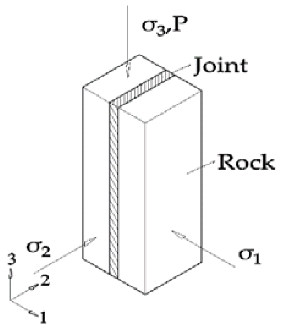
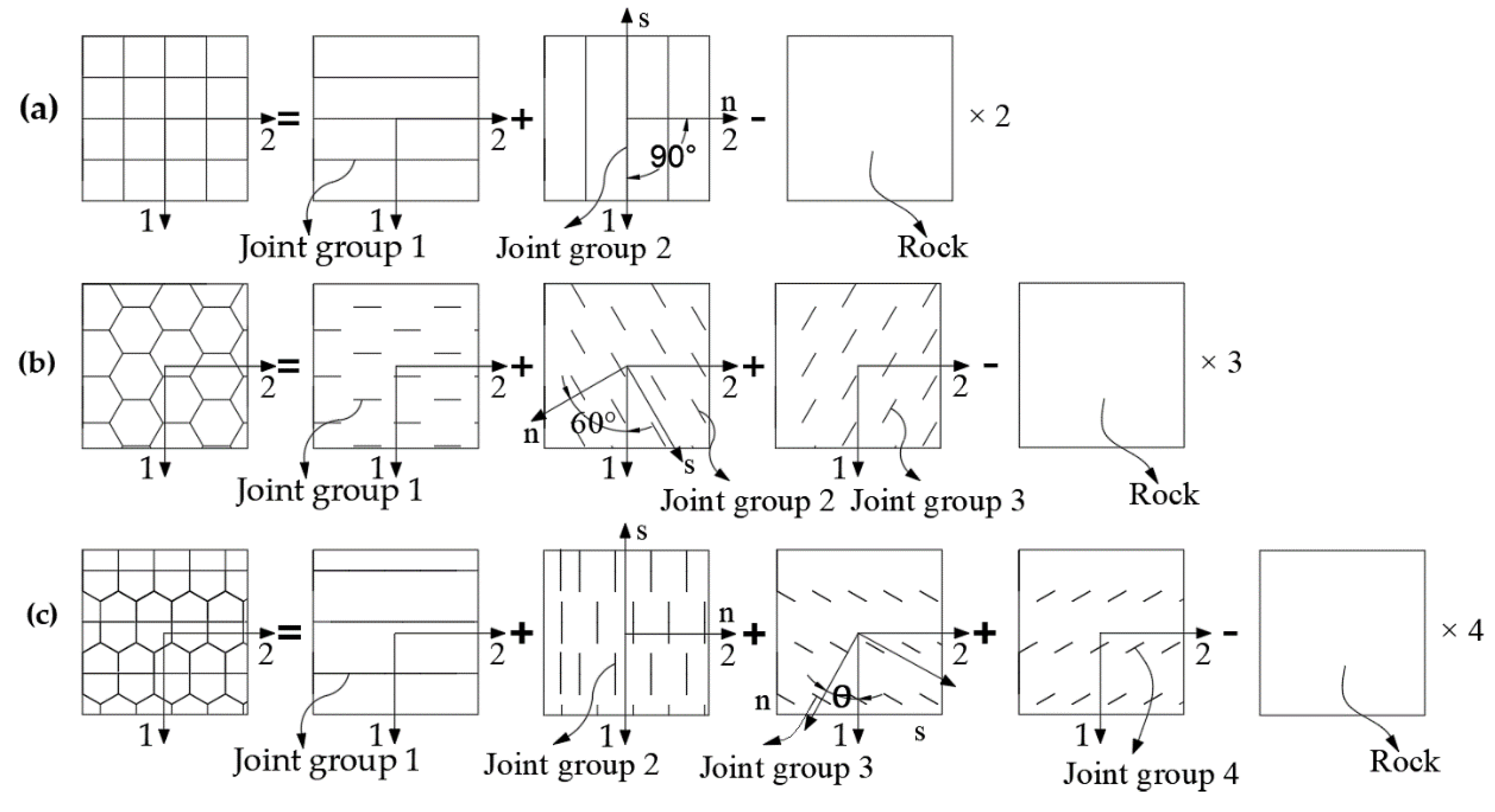
3.2. Constitutive Equation of Joint in the 1-2 Plane

In the 1-2 plane, the flexibility matrix of CJRM can be expressed as:
[ S ] = [ S 11 S 12 0 S 21 S 22 0 0 0 S 66 ]
where Sij are the composite engineering coefficients. In order to estimate the composite engineering constant of DJRM on the 1-2 plane, the Quadrilateral, Hexagonal and Pentagonal prism models are divided into jointed rock mass and intact rock mass. The flexibility matrix can be solved as shown in Figure 5.
Taking the Hexagonal prism models as an example, it can be split into three sets of joints in the plane, forming a 60° angle with each other, and the joint connection rate is 1/3. There are some joints whose main direction is not parallel to axis 1 and axis 2, so it is necessary to consider the stress-strain relationship of a single group of joints in the X and Y coordinate system after the deflection of the main direction. Ignoring the influence of the intersection of joints, using the superposition principle, the equivalent flexibility matrix in the 1-2 plane of the Hexagonal prism CJRM can be obtained as follows:
[ S ] = [ S ] 0 + [ K ( π / 3 ) ] T [ S ] 0 [ K ( π / 3 ) ] + [ K ( 2 π / 3 ) ] T [ S ] 0 [ K ( 2 π / 3 ) ] 3 [ S ] r
where [S]0 corresponds to the flexibility matrix of the joint group whose spindle is parallel to the 1-2 axis. [K(φ)] is the plane coordinate transformation matrix, and its expression is as follows:
[ K ( ϕ ) ] = [ cos 2 ( ϕ ) sin 2 ( ϕ ) 2 sin ( ϕ ) cos ( ϕ ) sin 2 ( ϕ ) cos 2 ( ϕ ) 2 sin ( ϕ ) cos ( ϕ ) sin ( ϕ ) cos ( ϕ ) sin ( ϕ ) cos ( ϕ ) cos 2 ( ϕ ) sin 2 ( ϕ ) ]
Using MATLAB software, the composite engineering coefficients in the Hexagonal flexibility matrix are follows:
S 11 = S 22 = 9 E r 3 ( 1 L j ) ( E r K n t j ) 8 [ E r 0.33 ( E r K n t j ) ] E r + 3 G r A j + 2 K s t j 8 G r K s t j + 9 8 E r ( 1 L j ) 3 ν r + 4 4 E r S 12 = S 21 = 3 E r ( 1 L j ) ( E r K n t j ) 8 [ E r 0.33 ( E r K n t j ) ] E r 3 G r A j + 2 K s t j 8 G i K s t j + 3 8 E r ( 1 L j ) 5 ν r 4 E r S 66 = 3 E r ( 1 L j ) ( E r K n t j ) 2 [ E r 0.33 ( E r K n t j ) ] E r + 3 G r A j + 2 K s t j 2 G r K s t j + 3 2 E r ( 1 L j ) + 3 ν r E r 3 G r
According to the composite solution method shown in Figure 4, the joint flexibility matrix of the Quadrangular prism and the Pentagonal prism model is also available.

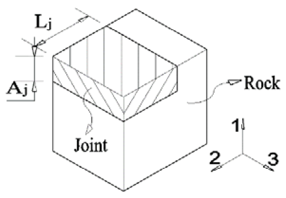
3.3. Establishment of Three-Dimensional Joint Flexibility Matrix

When the joint flexibility matrix in the two-dimensional plane of the CJRM is established, due to the influence of the hidden joint and the deflection angle of the column axis, directly expanding the flexibility matrix into the three-dimensional space will cause errors. Since there are a large number of hidden joints in the direction of the column axis, the column along the column axis direction is cut transversely by the joint into a discontinuous prismatic structure, so there is a stress concentration phenomenon. When solving the positive-axis elastic constant in three-dimensional space, it is necessary to consider the vertical offset of the joint. At the same time, due to the geological structure of the actual rock formation, the main direction of the material does not coincide with the direction of the geodetic coordinate axis. The deflection angle that often exists between the two coordinate systems needs to be considered when solving the flexibility matrix.
To calculate the elastic parameters of the column axis direction, Singh established a hidden joint model considering the vertical offset of the joint, and gave the calculation formula of the elastic constant as follows:
E n = E r 1 + b n n E r k n h s n , G s n = G r s s s n k s h k s v s s s n k s h k s v + G r b s n s s k s v + G r s n k s h , ν s n = ν r k n h s n k n h s n + b n n E r
where bnn and bsn are the concentration factors of normal stress and shear stress caused by joint offset, respectively, Fs is the vertical offset between adjacent hidden joints, and Ss and Sn indicate the joint spacing between parallel and vertical column axis directions, respectively.
After the spindle coordinate system is converted to the geodetic coordinate system, the transformation relationship of the flexibility matrix is as follows:
[ S ] X Y Z = [ T ( α , β , γ ) ] [ S ] 123 [ T ( α , β , γ ) ] T
where [S]XYZ and [S]123 represent the flexibility matrix in the geodetic coordinate system x-y-z and the material spindle coordinate system 1-2-3, respectively; [T(α,β,γ)] is the coordinate transformation matrix, α is the deflection azimuth angle, β is the dip angle, and γ is the steering angle.

3.4. Establishment of Permeability Coefficient KZZ of the Column-Axis Equation

By taking the parameters into the model, the strains {ε1, ε2, ε3, γ1, γ2, γ3} of the CJRM fissures can be obtained. For convenience of calculation, the joint arrangement of the Hexagonal prism and the Pentagonal prism model is simplified into a quadrilateral. This arrangement, applying the simplified approach proposed by Que [21], simplifies the geometric elements of the three models into a joint length S2 parallel to the X axis and a joint width S1 parallel to the Y axis; the cross-sectional shape of the Pentagonal prism and the Hexagonal prism model is simplified into a quadrilateral. This simplified method will lead to some errors when the variable angle θ ≠ 0 for the Pentagonal prism model, but the study by Que proved that this error is extremely small and can be ignored, and when θ = 0, the pentamorphic shape will become rectangular. The simplified cross-section is as shown in Figure 6:
By means of the above simplified method, the calculation formula of the fracture mechanical aperture in the X and Y directions in the X-Y plane can be obtained, and the equivalent hydraulic aperture can then be calculated according to Equation (3). If the rock is under the action of positive-axis three-phase stress, according to Premise (5), the permeability coefficients KZX and KZY corresponding in the X and Y directions can be expressed as follows:
K Z X = g b h x 12 μ x = g [ b x 0 ( 1 ε x ) 2 ] 12 μ x J R C 2.5 , K Z Y = g b h y 12 μ y = g [ b y 0 ( 1 ε y ) 2 ] 12 μ y J R C 2.5
where bhx and bhy are the equivalent hydraulic aperture of the X-axis and Y-axis, bx0 and by0 are the maximum aperture at zero normal stress of the X-axis and Y-axis, respectively. According to Premise (4), the permeability coefficient KZZ in the direction of the column axis can be solved as follows:
K Z Z = J f K Z X i = 1 n A x i + J f K Z Y j = 1 m A y j ( i = 1 n A x i + j = 1 m A y j ) J f = J f K Z X i = 1 n ( 1 ε x ) b x 0 S 1 + J f K Z Y i = 1 m ( 1 ε y ) b y 0 S 2 ( i = 1 n ( 1 ε x ) b x 0 S 1 + i = 1 m ( 1 ε y ) b y 0 S 2 ) J f
where Axi and Bxi are joint areas in the X-axis direction and the Y-axis direction, respectively. m and n are the number of joint groups of the X-axis and the Y-axis, respectively. By means of the above method, a formula is established for solving the permeability coefficient of CJRM in three-dimensional space.

4. Verification and Comparison of CJRM Seepage Constitutive Models

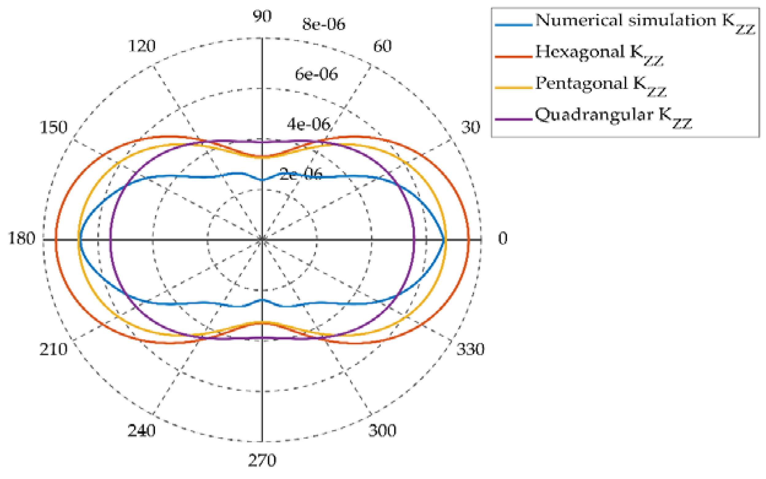
4.1. Comparison and Analysis of Three Constitutive Models and Numerical Simulation Results

Baihetan Hydropower Station is located in Sichuan Province, China, which is the second cascade power station developed by the cascade of the mainstream of the lower reaches of the Jinsha River. It has the benefits of generating electricity, while also acting as flood control and sand blocking. In the dam area, the most obvious stratigraphic lithology is basalt, which belongs to the Emeishan (Emei Mt.) formation of the Permain System (P2β) [1].
Combined with the in situ test results and numerical simulation results of the columnar jointed rock stratum P2β33-2 carried out in the dam site area of Baihetan Hydropower Station, the constitutive equation of the CJRM anisotropic seepage is verified. To study the influence of the water level variation on the safety of the dam foundation, Xiong [18] used the improved Voronoi algorithm to construct a three-dimensional columnar model of the columnar jointed rock mass of the Baihetan dam foundation, the analysis and calculation of the seepage tensor of the Baihetan dam foundation were carried out by 3DEC discrete element software. The numerical model is shown in Figure 7.
In the process of numerical simulation of columnar jointed rock mass, Xiong first established the columnar joint geometric model based on the columnar joint geometric parameters (l, tj, s, s3), and then employed the engineering parameters of the Baihetan (kn, ks, Er, Gr) to perform numerical calculations. The above parameter values are shown in Table 2. The head difference between the upstream and downstream of the Baihetan arch dam is 200 m, the pore water pressure of 2 MPa is added to the corresponding surface of the model, and the remaining surfaces are set as impervious surfaces. The outer boundary of the model is subject to displacement constraints. By changing the inclination angle β of the cylinder, different inclination angle coefficients of column axial permeability KZZ can be obtained. To verify the applicability of the constitutive model proposed in this paper, the parameters used in the constitutive equation are the same as those used in the numerical simulation. The permeability coefficients of columnar jointed rock masses at different deflection angles were calculated by using the Quadrangular prism, Pentagonal prism, and Hexagonal prism models, and the differences between the calculation results of the three seepage constitutive models and the numerical simulation results obtained at the same inclination were compared and analyzed.
The calculation programs for the Quadrilateral, Hexagonal and Pentagonal prism seepage constitutive models were calculated in MATLAB software. According to the mechanical characteristics of the Baihetan project, the optimal variable angle of the Pentagonal prism was determined to be θ0 = 0.8698 rad by inversion calculation. In the calculation process, a calculation method with equal circumference is adopted. Therefore, the contour of the method plan was selected to ensure that the different models had the same joint area. The polar coordinate diagram of the permeability coefficient value of the column axis direction changed with the deflection angle of the prism, as shown in Figure 8, and the calculation results were compared and analyzed.
It can be seen from Figure 8 that the permeability coefficients of the three models have the following laws: under the same deflection angle, the permeability coefficient of the Quadrangular prism model is the largest, and the permeability coefficient of the Pentagonal prism model is larger than that of the Hexagonal prism model. In addition, the permeability coefficients of the three models all achieve the minimum value when β=n∙90°(n=1,3), and the maximum value when β = (n − 1)∙90°(n = 1,3). The reason for this can be attributed to two aspects, one is the geometry of the model, and the other is the force characteristics of the model.
(1) The difference in the joint dependent variables depends on the differences in the geometric characteristics of the three models. The reason for this difference is that the three apex angles of the hexagonal plane around a point in the Hexagonal prism model are mutually interlocked. When the shear force acts, the joints and the prisms are mutually constrained, and the structure is at its most stable. The planar quadrilateral joint is composed of two sets of completely penetrating joints. When β = n∙90°(n = 1,3), the shearing force is along the joint direction, the displacement limitation between the cylinders is weak, and the structure is most vulnerable. The pentagonal plane combines the structural characteristics of the above two models, and is composed of three sets of incompletely through joints and one set of completely through joints, that is, there is a complete through joint surface and there is also mutual engagement between the prisms, and the structural stability is second only to the planar Hexagonal structure.
(2) When the deflection angle of the prism is β = n∙90°(n = 1,3), the confining pressure acts completely on the closing effect of the joint, so the strains of the three models are larger, resulting in smaller joint aperture, and correspondingly the coefficient of permeability is smaller; conversely, when the prism deflection angle is reduced to β = (n − 1)∙90°(n = 1,3), the confining pressure not only produces a joint closing effect, but also causes the joint to produce the shear slip effect along the column axis, resulting in the joint aperture becoming larger and the corresponding permeability coefficient becoming larger.
The permeability coefficients obtained by the three models are compared with the permeability coefficients obtained by numerical simulation experiments. When the prism deflection angle is β = (n − 1)∙90°(n = 1,3), that is, when the prism body is not deflected, the curve obtained by the seepage constitutive model of the Pentagonal prism model is the closest to the curve obtained by numerical simulation. With the increase of the deflection angle, the difference between the numerical simulation results and the calculation results of the Pentagonal column joint seepage constitutive model increases gradually. When the deflection angle is β = n∙90°(n = 1,3), the difference between the two reaches its maximum. In the seepage process of the jointed rock mass under confining pressure, the change of joint aperture will affect its permeability coefficient. At the same time, the filling material in the joint will be deformed due to extrusion. The deformation causes the permeability coefficient to decrease, which is also the influencing factor of the permeability coefficient of the rock mass.
Based on this, it can be concluded that when the rock mass deflection angle is small, the joint flexibility constitutive model derived from the linear elastic theory can used to approximately calculate the corresponding joint aperture, thereby calculating the permeability coefficient. When the prism deflection angle is large, there is a big change in the degree of joint aperture. There is a certain error in the calculation of the linear elastic model. It is necessary to consider the change of the permeability of the internal filling material itself.

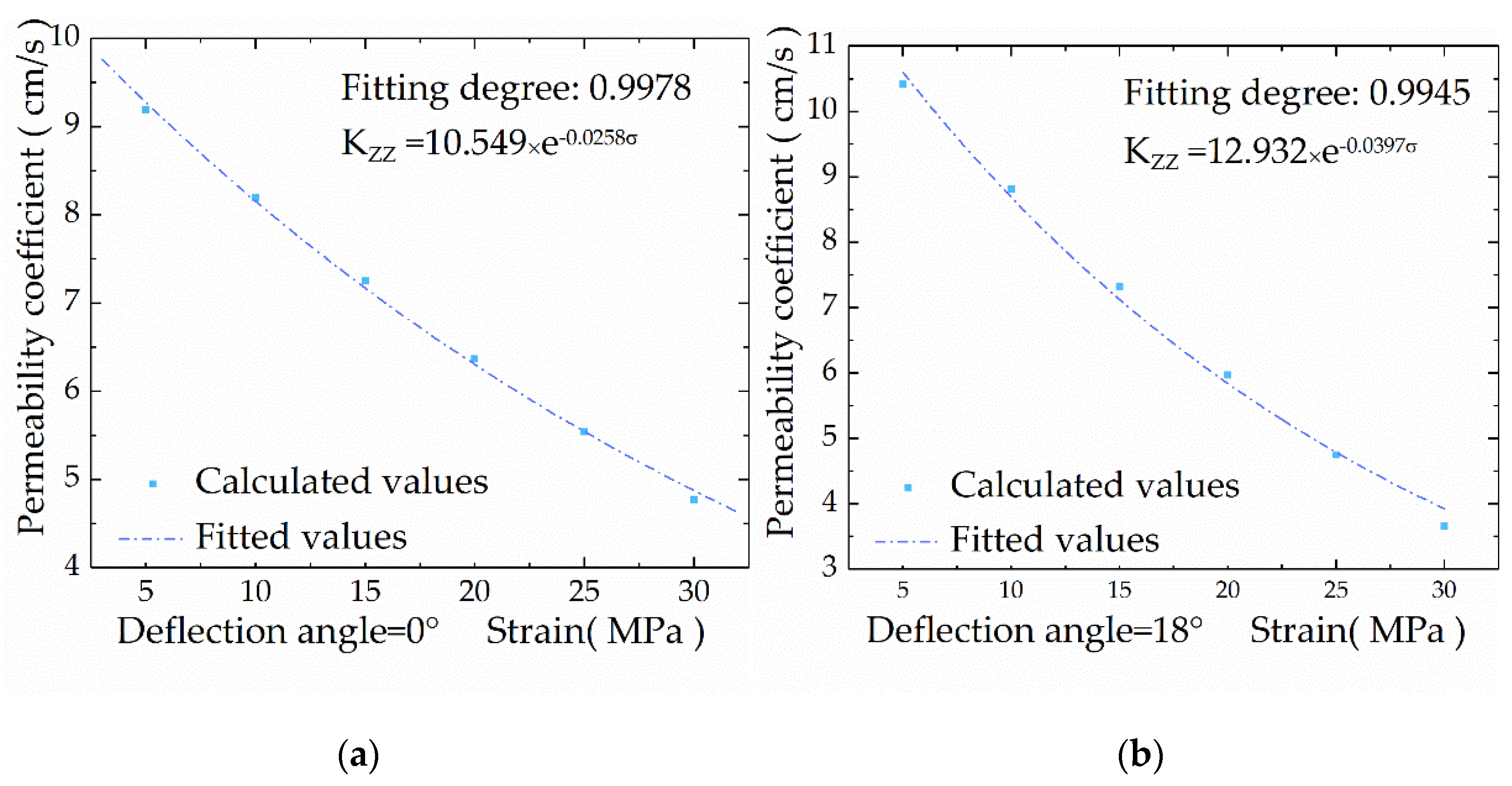
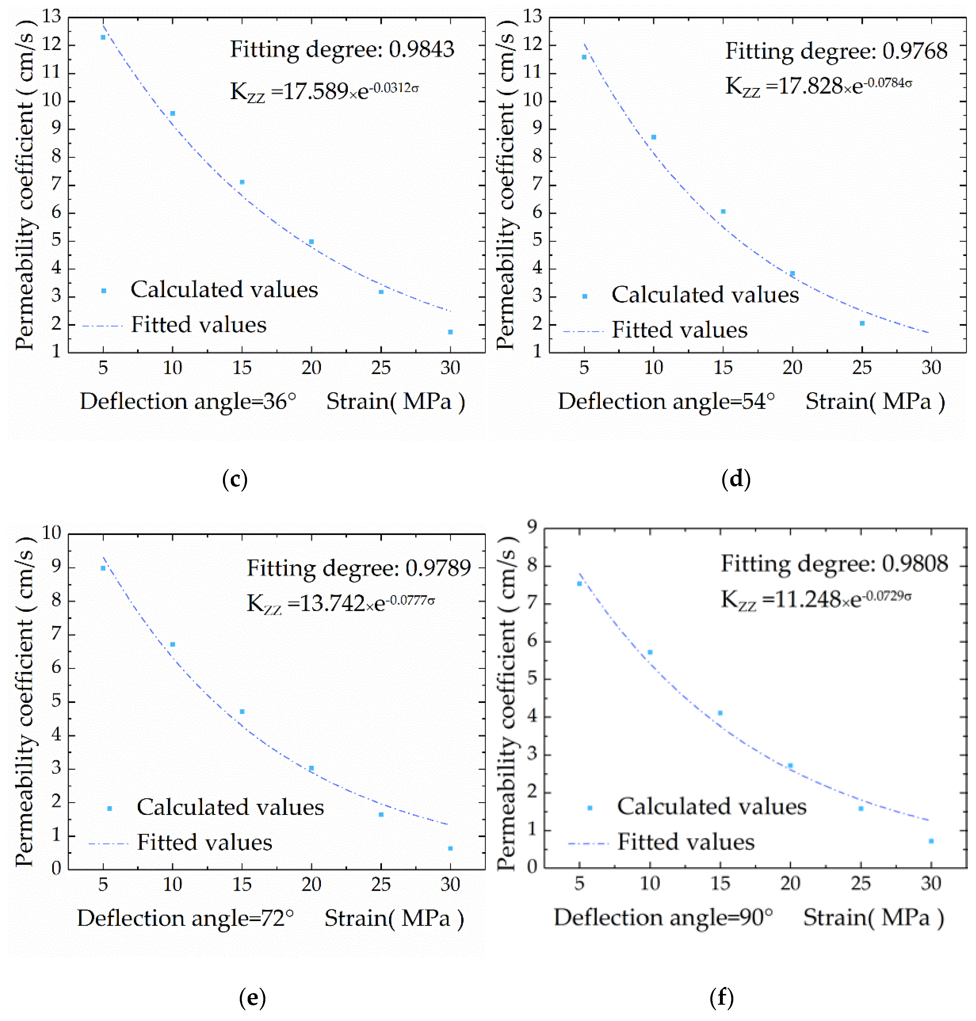
4.2. The Variation Law of Permeability Coefficient of Pentagonal Prism Model with Confining Pressure

It can be understood from Section 4.1 that the Pentagonal prism model is better able to describe the seepage characteristics under different deflection angles of Baihetan, in order to verify that the permeability coefficient curve under different confining pressures satisfies the empirical formula of the permeability coefficient of fractured rock masses, the Pentagonal prism seepage model under different deflection angles is analyzed, and four different deflection angles (15°, 30°, 45°, 60°) are selected.
Figure 9 shows that as the confining pressure increases, the permeability coefficients are reduced; as the deflection angle decreases, since the normal stress and the shear stress no longer only cause the corresponding line strain and shear strain, a tensile-shear coupling effect will occur, and the joint opening degree under the same confining pressure becomes large. The corresponding permeability coefficient will increase accordingly. The coefficient-confining pressure fitting variation law can be expressed by the formula KZZ = aK0 exp(−bσ). Both a and b parameters in the formula are related to the joint feature. Due to the introduction of three-phase stress, the three-phase stress will have an effect on the parameter b. The multivariate regression fitting curve and the Louis, Peuga and other scholars have the same form for the formula obtained from the normal stress, which can be expressed as a negative exponential function of pressure, as shown in Formula (5). Therefore, the constitutive model proposed in this paper expands the previous empirical formula, and is better able to describe the permeability characteristics of CJRM.

5. Conclusions

To study the seepage characteristics of CJRM, the Pentagonal prism model was added on the basis of the commonly used Quadrangular prism and Hexagonal prism models, and the corresponding three-dimensional seepage constitutive model considering hidden joint and prism deflection angle was established. According to the CJRM of Baihetan, the parameters of three constitutive models were determined by in situ test results, and the calculation results of the three models were compared with the numerical simulation results. The main conclusions are as follows:
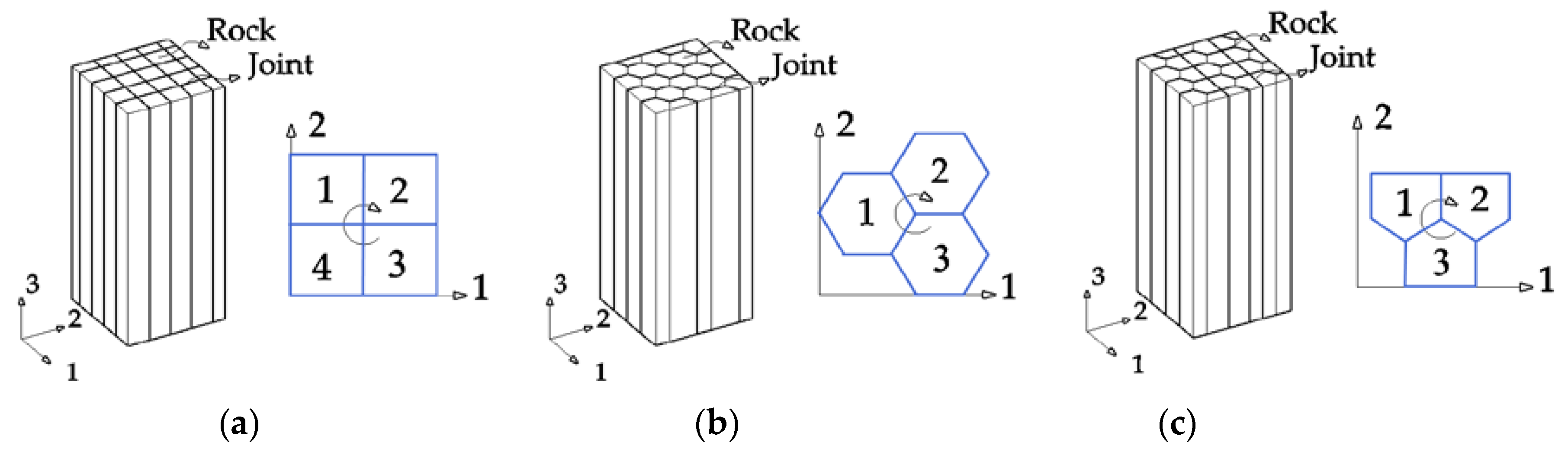
  • The three models applied to the Baihetan project were able to reflect the basic seepage characteristics. Compared with the Quadrangular prism and the Hexagonal prism model, the calculation results of the Pentagonal prism model were most consistent with the numerical simulation results. This is because the Pentagonal prism model not only has a completely penetrating joint, but also a mutual bite between the prisms, which is able to truly reflect the seepage characteristics of the columnar jointed rock mass.
  • The permeability coefficients calculated by the seepage constitutive model of the three columnar jointed rock masses reached their minimum when the deflection angle of the prism was β = n∙90°(n = 1,3), and reached their maximum when the deflection angle of the cylinder was β = (n − 1)∙90°(n = 1,3). This is because at β = n∙90°(n = 1,3), the confining pressure of the column is completely converted into normal stress, and the joint strain is high. As the deflection angle gradually decreases to β = (n − 1)∙90°(n = 1,3), the partial confining pressure causes the joint shear slip, and the joint strain becomes smaller, leading to a larger permeability coefficient of the joint.
  • The law of permeability coefficient with the change of confining pressure calculated by the seepage constitutive models proposed in this paper can be expressed as a negative exponential function, which conforms to the general law of seepage of jointed rock mass, and expands the solution method for the permeability coefficient of columnar jointed rock mass under stress field.
In this paper, the theoretical solution method is used to obtain the joint flexibility matrix of CJRM, and then the permeability coefficient is solved. This method is able to solve the stress-dependent seepage problem in linear elasticity. However, as the joint aperture decreases, the JRC of the joint plane and the joint connectivity rate change, which leads to the change of the permeability coefficient of the jointed rock mass and causes errors in the calculation results. Subsequent research will fully consider the impact of changes in joint permeability and further enrich the research results.

Author Contributions

Methodology, Z.N., Z.Z. and X.Q.; Formula Derivation, Z.N. and X.Q.; Figures & Tables, Z.N. and Z.Z.; Writing, Z.N. and Z.Z.; Data analysis, Z.N., Z.Z. and X.Q.; Project Administration, Z.N. and Z.Z.; Resources, Z.N. and Z.Z.; Funding Acquisition, Z.N., Z.Z. and X.Q. All authors have read and agreed to the published version of the manuscript

Funding

This research was funded by the National Natural Science Foundation of China (Grant No. 41831278 and 51579081).

Conflicts of Interest

The authors declare no conflict of interest.

References

  1. Meng, Q.; Yan, L.; Chen, Y.; Zhang, Q. Generation of Numerical Models of Anisotropic Columnar Jointed Rock Mass Using Modified Centroidal Voronoi Diagrams. Symmetry 2018, 10, 618. [Google Scholar] [CrossRef] [Green Version]
  2. Hao, X.; Feng, X.; Yang, C.; Jiang, Q.; Li, S. Analysis of EDZ Development of Columnar Jointed Rock Mass in the Baihetan Diversion Tunnel. Rock Mech. Rock Eng. 2016, 49, 1289–1312. [Google Scholar] [CrossRef]
  3. Li, B.; Tao, L.; Xu, N.; Dai, F.; Tan, Y. Stability assessment of the left bank slope of the baihetan hydropower station. Int. J. Rock Mech. Min. Sci. 2018, 104, 34–44. [Google Scholar] [CrossRef]
  4. Dai, F.; Jiang, P.; Xu, N.; Chen, W.; Tan, Y. Focal mechanism determination for microseismic events and its application to the left bank slope of the baihetan hydropower station in china. Environ. Earth Sci. 2018, 77, 268. [Google Scholar] [CrossRef]
  5. Yan, D.; Xu, W.; Wang, W.; Shi, C.; Wu, G. Research of size effect on equivalent elastic modulus of columnar jointed rock mass. Chin. J. Geotech. Eng. 2012, 34, 243–250. (In Chinese) [Google Scholar]
  6. Kim, J.W.; Chong, S.H.; Cho, G.C. Experimental Characterization of Stress- and Strain-Dependent Stiffness in Grouted Rock Masses. Materials 2018, 11, 524. [Google Scholar] [CrossRef] [Green Version]
  7. Min, K.B.; Rutqvist, J.; Tsang, C.F.; Jing, L. Stress-dependent permeability of fractured rock masses: A numerical study. Int. J. Rock Mech. Min. Sci. 2004, 41, 1191–1210. [Google Scholar] [CrossRef] [Green Version]
  8. Baghbanan, A.; Jing, L. Stress effects on permeability in a fractured rock mass with correlated fracture length and aperture. Int. J. Rock Mech. Min. Sci. 2008, 45, 1320–1334. [Google Scholar] [CrossRef]
  9. Lu, T.; Xu, R.; Zhou, B.; Wang, Y.; Zhang, F.; Jiang, P. Improved Method for Measuring the Permeability of Nanoporous Material and Its Application to Shale Matrix with Ultra-Low Permeability. Materials 2019, 12, 1567. [Google Scholar] [CrossRef] [Green Version]
  10. Pan, D.; Zhang, N.; Xie, Z.; Feng, X.; Kong, Y. Laboratory Testing of Silica Sol Grout in Coal Measure Mudstones. Materials 2016, 9, 940. [Google Scholar] [CrossRef] [Green Version]
  11. Singh, B. Continuum characterization of jointed rock masses: Part I-The constitutive equations. Int. J. Rock Mech. Min. Sci. 1973, 10, 311–335. [Google Scholar] [CrossRef]
  12. Singh, B. Continuum characterization of jointed rock masses: Part II-Significance of low shear modulus. Int. J. Rock Mech. Min. Sci. Geomech. Abstr. 1973, 10, 337–349. [Google Scholar] [CrossRef]
  13. Gerrard, C.M. Elastic models of rock masses having one, two and three sets of joints. Int. J. Rock Mech. Min. Sci. Geomech. Abstr. 1982, 19, 15–23. [Google Scholar] [CrossRef]
  14. Gerrard, C.M. Equivalent elastic moduli of a rock mass consisting of orthorhombic layers. Int. J. Rock Mech. Min. Sci. Geomech. Abstr. 1982, 19, 9–14. [Google Scholar] [CrossRef]
  15. Yan, S.; Huang, Y.; Chen, C.Y. An equivalent model for jointed rock mass with persistent joint and its elastic parameters. J. Huazhong Univ. Sci. Technol. 2001, 29, 60–63. [Google Scholar]
  16. Meng, G.T. Geomechanical Analysis of Anisotropic Columnar Jointed Rock Mass and Its Application in Hydropower Engineering; Hohai University: Nanjing, China, 2007. [Google Scholar]
  17. Zou, L.; Tarasov, B.; Dyskin, A.V.; Adhikary, D.; Pasternak, E.; Xu, W. Physical modeling of stress-dependent permeability infractured rocks. Rock Mech. Rock Eng. 2013, 46, 67–81. [Google Scholar] [CrossRef]
  18. Xiong, G. Seepage Tensor Study and Engineering Application on Column Jointed Rock Mass of Dam Foundation. Master’s Thesis, Hohai University, Nanjing, China, 2017. [Google Scholar]
  19. Wang, H.; Xu, W.; Zuo, J.; Shao, J.; Jia, C. Evolution law of the permeability and porosity for low-permeability rock based on gas permeability test. J. Hydraul. Eng. 2015, 46, 208–216. (In Chinese) [Google Scholar]
  20. Chao, Z.; Wang, H.; Xu, W.; Jia, C.; Xia, J. Model tests on permeability of columnar jointed rock mass. Chin. J. Geotech. Eng. 2016, 38, 1407–1416. (In Chinese) [Google Scholar]
  21. Que, X.; Zhu, Z.; Lu, W. Anisotropic constitutive model of pentagonal prism columnar jointed rock mass. Bull Eng. Geol. Environ. 2020, 79, 269–286. [Google Scholar] [CrossRef]
  22. Lomize, G.M. Flow in Fractured Rock; Gosemergoizdat: Moscow, Russia, 1951; pp. 127–129. (In Russian) [Google Scholar]
  23. Louis, C. A Study of Groundwater Flow in Jointed Rock and Its Influence on the Stability of Rock Masses (Rock Mech. Res.Rep.10); Imperial College: London, UK, 1969. [Google Scholar]
  24. Louis, C.; Maini, Y.N.T. Determination of in situ hydraulic parameters in jointed rock. In Proceedings of the 2nd Congress ISRM, Beograd, Yugoslavia, 25–27 September 1970; pp. 235–245. [Google Scholar]
  25. Nelson, R.A. An experimental study of fracture permeability in porous rock. In Proceedings of the 17th U.S. Symposium on Rock Mechanics, Snow Bird, UT, USA, 25–27 August 1976; pp. 2A6–12A6-1. [Google Scholar]
  26. Bandis, S.C.; Lumsden, A.C.; Barton, N.R. Fundamentals of rock joint deformation. Int. J. Rock. Mech. Min. Sci. Geomech. Abstr. 1983, 20, 249–268. [Google Scholar] [CrossRef]
  27. Barton, N.; Bandis, S.; Bakhtar, K. Strength, deformation and conductivity coupling of rock joints. Int. J. Rock Mech. Min. Sci. Geomech. Abstr. 1985, 22, 121–140. [Google Scholar] [CrossRef]
  28. Yang, T.; Jia, P.; Shi, W.; Wang, P.; Liu, H.; Yu, Q. Seepage–stress coupled analysis on anisotropic characteristics of the fractured rock mass around roadway. Tunn. Undergr. Space Technol. 2014, 43, 11–19. [Google Scholar] [CrossRef]
  29. Zhang, C.; Zhu, Z.; Zhu, S.; He, Z.; Zhu, D.; Liu, J.; Meng, S. Nonlinear Creep Damage Constitutive Model of Concrete Based on Fractional Calculus Theory. Materials 2019, 12, 1505. [Google Scholar] [CrossRef] [PubMed] [Green Version]
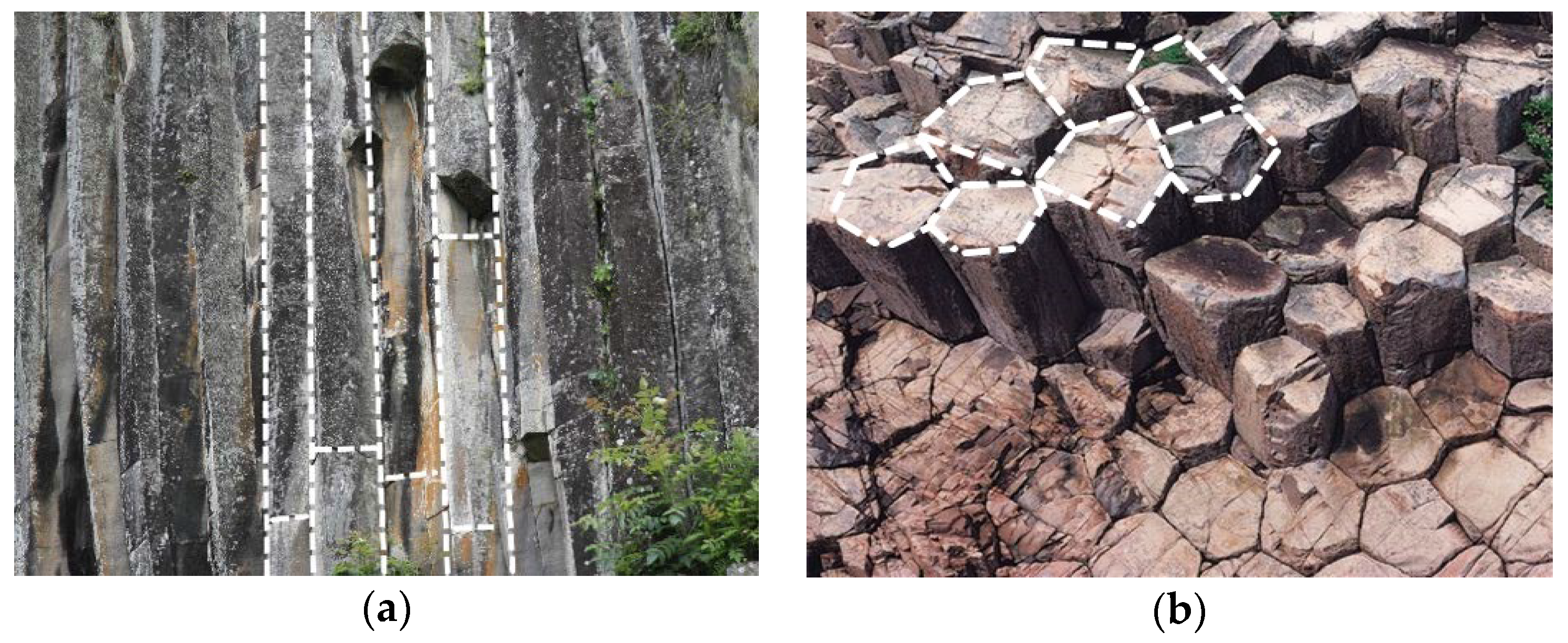
  30. Cui, J.; Jiang, Q.; Feng, X.; Li, S.; Liu, J.; Chen, W.; Zhang, J.; Pei, S. Insights into statistical structural charactestics and deformation properties of columnar jointed basalts: Field investigation in the Baihetan dam base, China. Bull. Eng. Geol. Environ. 2017, 77, 775–790. [Google Scholar] [CrossRef]
Figure 1. Typical columnar joint, pictured (a) parallel to the column axis direction; (b) perpendicular to the column axis direction.
Symmetry 12 00160 g001
Figure 2. Schematic diagram of three-direction stress of single fractured rock mass.
Symmetry 12 00160 g002
Figure 3. Typical columnar joint: (a) Quadrangular prism model; (b) Hexagonal prism model; (c) Pentagonal prism model.
Symmetry 12 00160 g003
Figure 4. Element model of discontinuous jointed rock mass.
Symmetry 12 00160 g004
Figure 5. Composite solution method for joint flexibility matrix of CJRM: (a) calculation method of Quadrangular flexibility matrix; (b) calculation method of Hexagonal flexibility matrix; (c) calculation method of Pentagonal flexibility matrix. s, and n are parallel and perpendicular to the direction of joint extension, respectively.
Symmetry 12 00160 g005
Figure 6. Simplified cross-section of Hexagonal and Pentagonal models: (a) simplified Hexagonal prism model; (b) simplified Pentagonal prism model.
Symmetry 12 00160 g006
Figure 7. Columnar joints with different joint deflection angles from Xiong: (a) deflection angle of 0°; (b) deflection angle of 30°; (c) deflection angle of 60°; (d) deflection angle of 90°.
Symmetry 12 00160 g007
Figure 8. Comparison of the permeability coefficient theoretical curve and numerical simulation curve.
Symmetry 12 00160 g008
Figure 9. Comparison of the permeability coefficient theoretical curve and fitted curve: (a) deflection angle of 0°; (b) deflection angle of 18°; (c) deflection angle of 36°; (d) deflection angle of 54°; (e) deflection angle of 72°; (f) deflection angle of 90°.
Symmetry 12 00160 g009aSymmetry 12 00160 g009b
Table 1. Statistical table of sectional shape of columnar jointed basalt body column in typical areas.
Location and CountryShape of Column Section
QuadrilateralPentagonHexagon
Craters of Moon (USA) (CAN)28%56%16%
Dunsmuir (CAN)14.5%46%33.5%
Lewiston (USA)7.5%45%41.5%
Devils Tower (USA)17%42%35%
BaihetanP2β33 (CHN)49%46%5%
The data comes from Que [21].
Table 2. Parameters of the columnar jointed rock mass.
kn (GPa/m)ks (GPa/m)Kf0 (cm/s)tj (m)Er (GPa)Gr (GPa)vrl (m)s3 (m)s (m)
100508.5991 × 10−365.1250.230.220.05
kn, ks normal stiffness and shear stiffness, respectively. Kf0 is the initial permeability coefficient. Er, Gr, vr are the elastic modulus, shear modulus and Poisson’s ratio, respectively, of the intact rock. l is the side length of CJRM, s3 is the average column length, and s is the vertical staggered distance between the adjacent hidden joints.

