Abstract
In this paper, dynamic characteristics of the symmetrical traction system with tensioned pulley acting on compensating rope is theoretically investigated. Due to the excitations from drum, the traction system will occur longitudinal and transverse vibration. In order to explore the differences between traditional traction system and tensioned traction system with different tensioned methods and seek the optimal method of vibration suppression, the damping cylinder and terminal tension acting on compensating rope between tensioned pulley and ground are placed. Caused by the change of the rope’s property, the system will produce different dynamic responses. Here, the differential-algebraic equations (DAEs) are derived using Hamilton principle. The transverse and longitudinal nonlinear coupling of ropes are considered. The generalized- method is selected to solve the DAEs. Based on the response characteristics of the system, the time-frequency characteristics with different terminal damping are obtained by CWT (continuous wavelet transform) and FFT (fast Fourier transform). From results, it can be seen that tensioned pulley plays an important role in suppressing transverse and longitudinal vibration of the symmetrical traction system compared with traditional traction system, especially by adding damping cylinder. The amplitude of system decreases exponentially with the increase of the terminal damping acting on tensioned pulley. Different running speeds of tensioned traction system are discussed. The results can inform the development of relevant mitigating strategies to minimize the effects of excessive vibrations.
1. Introduction
The traction system has been widely used in many lifting fields, such as elevators, mining hoisting cableway, belt conveyors and cranes. The lifting system consists of four major components: driving drum, lifting rope, compensating rope and conveyances. Caused by the elasticity of the ropes, vibration phenomenon will occur under the excitation of the drum, which will even occur large resonance phenomenon. The dynamical characteristic and vibration controlling method of rope drives have been studied by many researchers. Li [1] established an electric pulley cableway model in banana plantation by Lagrange equations. The dynamic characteristics were analyzed theoretically and experimentally. Feng Huirong [2] analyzed the carrying rope bouncing and the free vibration due to the instant elastic energy release at cargo’s unhooking based on the theory of string vibration. The results provide some guidance for the installation design, the improvement of the technology and the safety code of practice for forestry aerial cableways. Pi [3] addresses the vibration control of beams subjected to a moving mass and modeled based on Hamiltonian principle. A method combining SMC (sliding mode control) and PPF (positive position feedback control) is proposed to suppress the transverse vibration of the beam when the moving mass is on and off the beam. Liu [4] established an axially moving belt system with input restriction and proposed a boundary control strategy reduce the vibration. Nguyen [5] proposed a control algorithm that suppresses the transverse vibrations of an axially moving belt system by the conjugate gradient method. In this paper, the proposed control method is to regulate the axial transport velocity of the membrane so as to track a desired profile according to which the vibration energy of the membrane at the end of transport decays most quickly. Different from cableway and belt conveyors, this traction system is a typical of lifting system with distributed mass and time-varying length. Therefore, its dynamic characteristics can’t be expressed by an analytical solution. For this problem, many researches have been carried out. As for the mining lifting rope system, Stefan Kaczmarczyk [6] established longitudinal and transverse coupled mathematical model base on the Hamilton’s principle for a catenary-vertical lifting system to analyze passage through resonances based on a multi-scale method. Response of the transverse and longitudinal motion of ropes with conveyance is shown in [7], which is observed on the fast time scale and the slow time scale. Here, the results reveal adverse dynamic behavior of the catenary largely due to the auto-parametric interactions between the in- and out-of-plane modes and finds out the resonance modal interactions can be avoided to a large extent if the winding velocity is increased to an appropriate level. The transverse response of cable-guided hoisting system with time-varying length and the influence of vessel eccentricity is studied in [8,9]. Here, the transverse response of the moving hoisting conveyance in cable-guided hoisting system is investigated in this paper. In elevator system, the coupled vibration and vibration control method are also investigated by many researchers. Bao [10,11,12] and Zhang [13] established a unilateral transverse-longitudinal coupled vibration model based on Hamilton’s principle and solved the governing equations by the Galerkin method. The stability of the parameter vibration of the lifting system and natural frequency characteristics are analyzed. The results show that transient resonance will occur in elevator system when the frequency of transverse excitation of traction system is equal to or close to the natural frequency of the system. Parameter excitation has a greater impact on the longitudinal vibration of the lifting system, but a smaller impact on the transverse vibration. When the frequency of parameter excitation is close to or equal to the natural frequency of the lifting system, parameter transient will also occur in the system which will become beat vibration. In [14], the results of a study of vertical vibrations caused by torque ripple generated at the elevator drive system is presented. Based on the experimental study, the reason of the system resonance is obtained in this paper, which is consistent with the simulation results.
The traction system is composed by multiple components. And here, the rope is regarded as continuum. Therefore, the established equation is differential-algebraic mixed equation with Lagrange multipliers, which can’t be solved by ordinary differential solver. For this kind of equation, many solutions are proposed. An accurate calculation with spatial discretization and substructure method is proposed in [15] to accurately calculate dynamic responses of one dimensional structure with multiple constraints. When the geometric matching condition is linear, DAEs (differential algebraic equations) can be transformed into ODEs (ordinary differential equations) by the substructure method. Martin and Olivier [16,17,18,19] proposed the generalized-α scheme for constrained mechanical systems. Here, the DAEs can be solved directly without conversion, which greatly improved the efficiency of solution.
An elevator system is a distributed parameter system, which will greatly increase the difficulty of vibration control. Vibration control in the lifting process is an essential goal. As for transverse vibration suppression method, a nonstationary sliding mode control method is proposed in [20], which can suppress the transverse vibration of ropes and conveyances to a certain degree. Wang [21] constructed a dynamic model of the flexible guided lifting bucket based on the continuum theory and the generalized Hamiltonian principle. In this paper, the adaptive boundary control method is proposed for position regulation and vibration degradation of the system, where adaptation laws and a boundary disturbance observer are formulated to handle system uncertainties. Wang [22] analyzes the traction system of the tensioned compensating rope and traditional suspension compensating rope, and finds out that the longitudinal vibration of the system can restrain to a certain extent by tensioning compensating rope. In [10,12], the vibration control method of lifting system is proposed. Here, the lifting system is regarded as a unilateral system, and the vibration can be suppressed by tensioning unilateral compensating rope.
As for the dynamic interactions between components of setting tension pulley at compensating rope ring, a comprehensive mathematical model of a high-rise elevator system, taking into account the combined lateral stiffness of the roller guides and guide rails is established in [23]. It is found that the autoparametric internal resonance takes place between the transverse in plane and out of plane modes due to the effects of the cubic nonlinear terms and excitation of the building structure. Seiji Watanabe [24] established a mathematical model regarding the rope as a single degree of freedom spring without mass. The results show the vertical motion of the compensating sheave when the elevator in emergency and normal cases. The simulation results were validated by experiments.
Previous works have mainly focused on a unilateral lifting system or a lumped parameter system. In addition, the dynamic model is not complete for the lifting of a systematic traction system with compensating pulley tensioned at the bottom of the compensating rope. In particular, there is no systematic description of the dynamic response of the traction system under the condition of a compensating rope tension. Further, previous works are focused on the control method of transverse vibration of cableway development, belt conveyors, and lifts. The methods of longitudinal vibration suppression of traction systems haven’t been studied deeply. For this kind of large height vertical traction system with distributed parameters, it is impossible to realize the full status monitoring of any position of ropes and conveyances in reality. Active control needs status monitoring to obtain the feedback of the whole system’s state. Therefore, active control is not applicable for this kind of large height and distributed mass longitudinal traction lifting system. Compared with active control, the passive control method is more stable and reliable, and doesn’t need feedback. There is no study on the passive vibration suppression of vertical traction systems so far. Therefore, a passive control method is proposed to suppress system vibration by setting a tensioned pulley with a tensioned force and a damping cylinder at the bottom of the compensating rope. In this paper, a comprehensive coupled mathematical model of a high-rise traction system is established based on Hamilton principle. The dynamical of the traction system can be obtained by generalized-, which can reveal the vibration displacement of the system and the position of the resonance zone. Additionally, the natural frequency of the traction system can be obtained, which presents the veering phenomenon of the conveyances, lifting and compensating ropes subsystem. By applying different tensioning methods to the tensioning pulley, the dynamic response of traction lifting system under different working conditions can be obtained. Therefore, the effect of this passive vibration suppress method is also shown and discussed. The ideal tensioning method can be obtained to suppress the vibration of the system by comparing, which can be used to develop a relevant strategy to minimize the effects of excessive vibration and improve ride quality.
2. Modeling Description
2.1. Description of the System
The schematic diagram and technical solution of traditional and tensioned traction system is shown in Figure 1. As shown in Figure 1a,c, the traditional model is composed of these parts: driving drum, lifting ropes, conveyances, compensating ropes, guide rails, and guide wheels. In a traditional traction system, rotation of the driving drum drives the movement of ropes, and then the up and down movements of the conveyances. The guide wheels are set at the conveyances and limit the swing of conveyances through its matching with the guide rail. The compensating rope is in free suspension. Besides the above parts, as shown in Figure 1b, the tensioned model includes a tensioned pulley with a damping cylinder and tensioned blocks. The tensioned pulley is set at the bottom of compensating ropes, which is driven by compensating ropes. The technical solution of the tensioned traction system is shown in Figure 1d. It is supported by bearing. Further, it is guided vertically by linear slide rail. The tensioned blocks and damping cylinder are respectively placed on the upper and lower part of the tensioned pulley. Using self-gravity of tensioned pulley and tensioned blocks, the tensioned pulley can tension the compensating ropes and limit the swing of the tail of compensating rope. The system is arranged symmetrically. First of all, there are several assumptions made here to restrict the analysis.
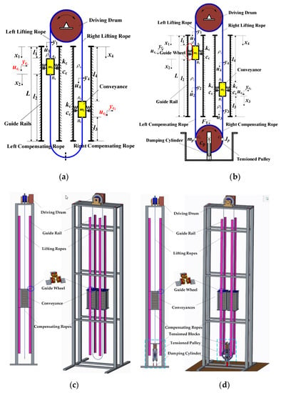
Figure 1.
Model of bilateral traction system with compensating rope tensioner. (a) schematic diagram of traditional traction system; (b) schematic diagram of tensioned traction system; (c) technical solution of traditional traction system; (d) technical solution of tensioned traction system.
(1) Since the cable bending stiffness is quite small [25], it is neglected in this paper;
(2) The mass per unit length ρi, (i = 1, 2, 3, 4) of ropes are both assumed to be uniform;
(3) Due to restriction of the guide rail, rotation of the conveyance is small enough which can be neglected. Therefore, longitudinal and transverse vibration of the conveyance is considered in this paper;
(4) The bending sections of the ropes in the groove arc of the driving drum and tensioned pulley are equivalent to that attached to the groove and its motion has no effect on the vibration characteristics of the system. Therefore, its vibration characteristics are ignored here. Therefore, the rope of the system is divided into four sections: left lifting rope, right lifting rope, left compensating rope and right compensating rope [23].
The dynamical response of the elevator ropes subjected to dynamic loading due to excitation from drum are represented by the longitudinal and transverse displacements denoted as and , where the subscript corresponds to sections of the ropes’ length , respectively. Here, , , and , is the measurement, longitudinal vibration, transverse vibration and length of left lifting rope, left compensating rope, right compensating rope and right lifting rope correspondingly.
Here, the compensation rope and lifting rope on the same side are complementary. Therefore, equality can be obtained: , . . is the length of conveyances and is the length of guide rail.
Because the tensioned pulley is equipped with guide rail, the tensioned pulley is restricted to move in the longitudinal direction only. Here, and are the longitudinal displacement and rotation of the tensioned pulley. Based on the previous assumptions, dynamic responses of the conveyance are represented by the longitudinal and transverse dynamic displacements, which are donated as and , .
2.2. Derivation of the Accurate Mathematical Model
Based on the physical model of the previous section, using energy method of analytical mechanics, the kinetic energy of the system is given as follows:
where
The potential energy of traction system is a function of vibration displacement, which is given as follows:
where the symbols and stand for the modulus of elasticity and cross-sectional area of ropes. Further, stand for the elastic strain of ropes. , donate the tension of the compensating and lifting rope. Specific expressions are provided in Appendix A.
The gravitational potential energy of traction system is given as follows:
During the lifting progress, the cable will be affected by distributed damping force. Therefore, the virtual work done by the non-conservative force on the system can be represented as:
where, and , are the damping of ropes.
Except that, there still exists forces concentrated at the boundary affecting the system. Additionally, those are: the interaction forces between the conveyances and lifting(compensating) ropes and the interaction forces between the tensioned pulley and compensating ropes. Specific expressions of virtual work are provided in Appendix B.
Here, the governing of the equation can be derived from Hamilton’s principle:
Substituting Equations (1)–(4) and Appendix B into the Hamilton’s principle Equation (5), the governing equations of the system can be obtained as follows:
Meanwhile, the time boundary conditions and geometric boundary conditions of the system are applied in the above operation process, namely:
The longitudinal and transverse force boundary conditions can be obtained as Equation (11).
And the geometric boundary conditions are:
Furthermore, governing equations and the boundary condition which consists of geometric boundary conditions and force boundary conditions of the traction system are shown in Equations (11) and (12).
As shown in above section, the governing equation is a mixed partial and ordinary differential equations with infinite dimension in mathematical form. Many parameters are time-varying, so they can’t be obtained by analytical method, only by numerical method.
In order to facilitate solving the governing equation, the lifting rope with non-homogeneous boundary condition should be translation in two parts: homogeneous and non-homogeneous boundary condition to get the general result. Further, the following transformation is introduced:
Furthermore, the excitation function is approximately a function of linear distribution, where is shown as follows:
Substituting Equation (13) into Equation (7), the transverse governing equation can be obtained:
The Specific expressions of are provided in Appendix C.
As for the transverse displacements of compensating ropes and , the transverse excitation mainly comes from the excitation introduced from the boundary of conveyances. Therefore, the excitation is introduced through the boundary. Further, the following transformation is introduced:
Substituting Equation (16) into Equation (7), the transverse governing equation of the compensating ropes can be obtained:
where,
Here, a discrete model can be derived via the Galerkin method. We define the one non-dimensional parameter as ,. .
According to the chain derivation rule, the partial derivatives of time t and space x can be obtained as follows:
where, is a symbol of , and . is a symbol of , and .
Based on the continuous characteristics of ropes, the dynamic displacement coordinates can be approximated using the assuming modal method (AMM). The transverse and longitudinal displacement of lifting and compensating rope are assumed as follows:
where and denote the included discrete order of the lifting and compensating rope longitudinal and transverse displacements, respectively. and are the generalized coordinates of the traction system. and are the corresponding trial functions that satisfy the homogeneous boundary conditions and constraint equations of the system. Further, the specific form of the selected trial function is shown in Appendix D.
Applying Green’s formula yields the discretized equations as follows:
where , and are the mass, damping, stiffness, and force matrices of longitudinal(transverse) vibration, respectively. and are the coupling terms introduced by the interaction between transverse and longitudinal vibration.
and are the total of generalised displacements of longitudinal and transverse vibration, which can be written as:
represents the constraint equations. and is a Jacobian matrix of the constraint equations, which can be written as:
The entries of the matrices and force vector of the Equation (20) are listed in Appendix E. Rewritten as a unified matrix form:
Equation (23) is a mixed-differential-algebraic equation. Because the constraint equations and their Lagrangian multipliers need to be discrete, there are difficulties with a numerical solution. Here, the generalized- algorithm is selected to solve the mixed differential-algebraic equation.
The basic iterative form of the algorithm is as follows:
where, h = tN+1-tN is time step; and N represents the Nth time step; represents the value of a generalized coordinate at ; the vector of acceleration-like variables is defined by the following recursive relationship:
Optimal algorithmic parameters , , and are proposed to second-order ODEs by Chung. The numerical solution is obtained by a predictor-corrector strategy as for the algorithm.
At the correction step, it needs to use Newton iterative algorithm to solve the moving unknown force and the generalized coordinates in each integral step simultaneously. The iterative equation can be transformed into the following form:
where, and denote the residual vectors of equilibrium and constraints. Further, denotes the augmented tangent matrix expressed in the following form:
where, .
Through multi-step iteration, the differential-algebraic equations can be solved, meaning the dynamical responses of the traction system can be obtained.
3. Study Case
To obtain dynamical responses, numerical simulations were applied to bilateral traction system. The typical parameters for system are defined as following Table 1.

Table 1.
Key parameters.
In the following results, the static displacement caused by gravitational potential energy is ignored. As shown in the following figures, the generation of the excitation is due to the non-roundness of the drum, so the frequency of the excitation is related to the running speed of the drum, which can be expressed as , where is the linear speed of drum operation, is the radius of drum, is the frequency of excitation. Further, the expression of following symbols is in the nomenclature of appendix, such as , , , and so on.
3.1. Comparison between Traditional Traction System and Tensioned Traction System
The model of traditional traction lifting system is shown in Figure 1a. The dynamical behaviour of traditional traction system has been studied by many scholars. In previous studies, most scholars have considered the compensating rope as a time-varying concentrated mass attached to the conveyance. Wu [26] obtained the transverse vibration characteristics of a traditional traction system. In this paper, by assuming the equivalent mass of balance rope with time-varying length lumped on conveyance, a transverse vibration model for mine friction hoist was established in accordance with the Hamilton’s principle. Chang [27] established the finite element vibration model of multi-rope friction lifting system with tension balancing device. In this paper, the compensating rope is also equivalent to the mass block added on the container. The compensating rope is directly suspended and not tensioned in traditional traction system, which means its property is only inertia and no stiffness. Therefore, it can be regarded as a time-varying mass attached to the conveyance. The mass of compensating rope is equal to the product of line density and the length of the compensating rope. Therefore, this value varies with time. Using a numerical solution, the dynamic characteristics of the traditional traction system can be obtained. Here, gravitational potential energy and static displacement of the system under terminal tension is ignored.
Figure 2 shows the longitudinal vibration at the conveyance of tensioned and traditional traction system. In this figure, it can be seen that longitudinal displacement of tensioned traction system is much smaller than that of traditional traction system, especially in resonance regions. Caused by the change of physical properties of compensation rope, the resonance regions are also varying between two traction system. This can be proven by Figure 3. In this figure, the longitudinal natural frequency of traditional traction system is much higher than that of tensioned traction system, which results in variation of the intersection between frequency of excitation and natural frequency. Furthermore, it affects positions of the resonance regions.
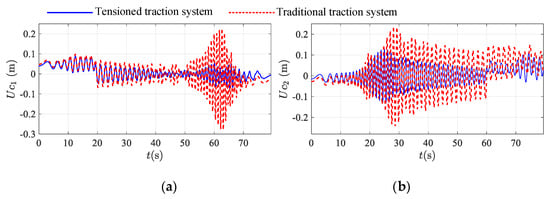
Figure 2.
Comparison of the longitudinal displacement at the conveyance between tensioned traction system with a terminal tension (blue line) and a traditional traction system (red line): (a) the ascending conveyance; (b) the descending conveyance.
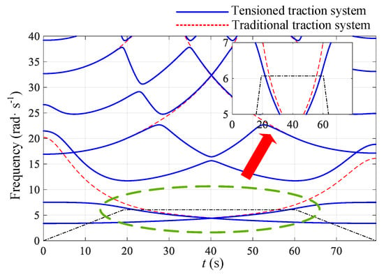
Figure 3.
Longitudinal natural frequency comparison between tensioned (blue line) and traditional (red line) traction system.
Three dimensional longitudinal displacements diagram of any point on lifting ropes with time are shown in Figure 4 and Figure 5, where the coordinates represent position of ropes , time and longitudinal displacement I = 1,4, respectively. As shown in Figure 2, is the longitudinal displacement of left lifting rope. Furthre, is the longitudinal displacement of right lifting rope. Because the rope length of the lifting rope changes with time, in order to show the overall response of the lifting ropes, it is dimensionless as . Here, we set as . Thus, .
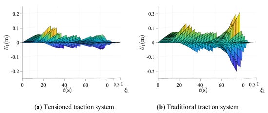
Figure 4.
Longitudinal displacement of the left lifting rope: (a) tensioned traction system; (b) traditional traction system.
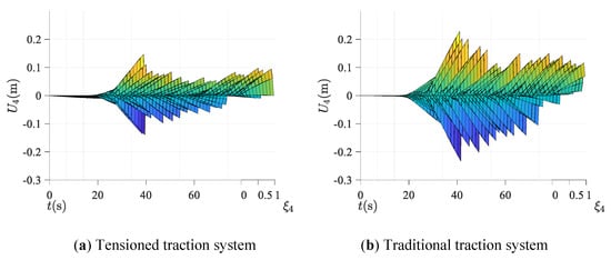
Figure 5.
Longitudinal displacement of right lifting rope: (a) tensioned traction system; (b) traditional traction system.
From the result, it can be seen that the longitudinal vibration of lifting ropes can be well restrained in the whole operation stage due to the terminal tension acting on the compensating rope. Especially when the rope resonates, the amplitude of longitudinal displacement of tensioned traction is much smaller than that of traditional system.
Figure 6 shows the comparison of transverse vibration at the conveyance of tensioned and traditional traction system. In this figure, it can be seen that in ascending process, the terminal tension acting on the compensating rope doesn’t affect the transverse vibration at the conveyance. But in the descending progress, the application of tension can restrain the transverse vibration to some extent. Especially in the resonance region from 20s to 60 s, it can better suppress the transverse vibration.

Figure 6.
Comparison of the transverse displacement at the conveyance between a traction system with a terminal tension (blue line) and a traditional traction system (red line): (a) the ascending conveyance; (b) the descending conveyance.
Three dimensional transverse displacements diagram of any point on lifting ropes with time are shown in Figure 7 and Figure 8, where the coordinates represent position of ropes , time and transverse displacement i=1,4, respectively. As shown in Figure 2, is the transverse displacement of left lifting rope. Further, is the transverse displacement of right lifting rope. The left figure is the transverse displacement of tensioned traction system. The right figure is the transverse displacement of traditional traction system. Compared with the traditional traction system, it is found that the application of terminal tension to tension compensating rope can restrain the transverse vibration of lifting ropes, especially in the resonance region, which is consistent with the change trend at the conveyance. The suppression effect can be clearly seen in Regions A and B of Figure 7 and Figure 8. In Region A, it can be seen that the resonance phenomenon, which occurs in traditional traction system, is eliminated with terminal tension acting on compensating rope to make it in tensioned state. Further, the overall transverse amplitude of the system is also reduced a lot.
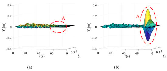
Figure 7.
Transverse displacement of left lifting rope: (a) tensioned traction system; (b) traditional traction system.
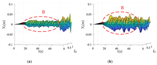
Figure 8.
Transverse displacement of right lifting rope: (a) tensioned traction system; (b) traditional traction system.
3.2. Discussion on Tensioned Pattern
3.2.1. Different Tension Acting on Tensioned Pulley
Figure 9, Figure 10 and Figure 11 shows the longitudinal response of the bilateral traction system at the ascending conveyance (Figure 9), descending conveyance (Figure 10) and tensioned pulley (Figure 11). Furthermore, the red, green, blue and yellow line stand for the response with terminal tension of N, N, N, N, respectively. From the results, it is evident that the amplitude and frequency of longitudinal vibration of the conveyances and tensioned pulley won’t change with the magnitude of the terminal tension acting on the tensioned pulley.
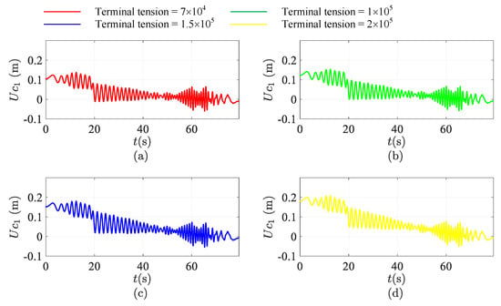
Figure 9.
The longitudinal response of the bilateral traction system at the ascending conveyance. (a) The red line: terminal tension = N; (b) the green line: terminal tension = N; (c) the blue line: terminal tension = N; (d) the yellow line: terminal tension = N.
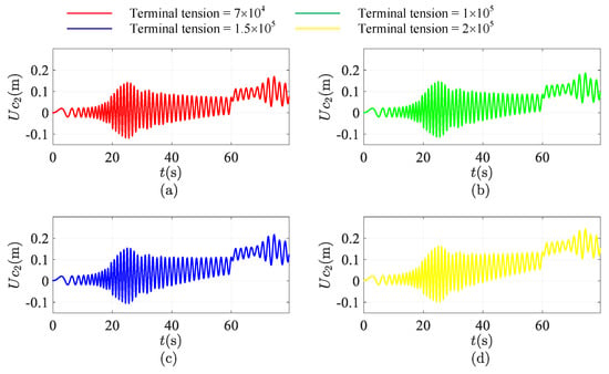
Figure 10.
The longitudinal response of the bilateral traction system at the descending conveyance. (a) The red line: terminal tension = N; (b) the green line: terminal tension = N; (c) the blue line: terminal tension = N; (d) the yellow line: terminal tension = N.
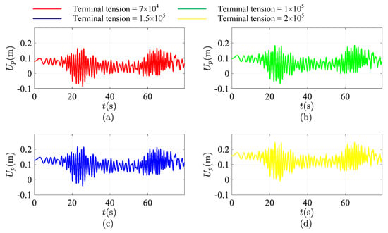
Figure 11.
The longitudinal response of the bilateral traction system at the tensioned pulley. (a) The red line: terminal tension = N; (b) the green line: terminal tension = N; (c) the blue line: terminal tension = N; (d) the yellow line: terminal tension = N.
However, in Figure 9 and Figure 10, the trend of longitudinal displacement is not horizontal. Due to the ascending and descending run of conveyances, the stiffness of lifting and compensating rope is time-varying. Here, gravity is ignored. However, the static displacement caused by the terminal tension acting on the tensioned pulley does still exist. This is the reason why the trend of the longitudinal displacement is declining. Further, it is evident that the angle of inclination is proportional to the magnitude of terminal tension. It can be concluded that the magnitude of terminal tension only affects the static displacement of the system. However, in terms of the characteristics of vibration, increasing the value of terminal tension has no effect on changes of longitudinal vibration characteristics of the bilateral traction system.
3.2.2. Different Damping Acting on Tensioned Pulley
In the above results, the compensating rope is just tensioned by adding terminal tension acting on the tensioned pulley. Compared with the traditional traction system, terminal tension can suppress the longitudinal vibration of the system to a certain extent. However, just as mentioned in Section 3.2.1, only increasing terminal tension can’t further suppress the vibration of the bilateral traction system.
Here, in order to suppress the vibration of the bilateral traction system more deeply, the damping cylinder is installed between the tensioned pulley and ground. Further, the dynamical response of system with terminal tension and damping cylinder acting on the tensioned pulley is shown in Figure 12, Figure 13, Figure 14 and Figure 15. Here, the terminal tension is set as N at all times.
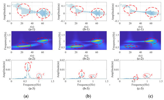
Figure 12.
Time-frequency characteristics of longitudinal response of the bilateral traction system at the ascending conveyance with terminal tension and damping cylinder acting on the tensioned pulley: (a) damping = 0; (b) damping = N/s; (c) damping = N/s.
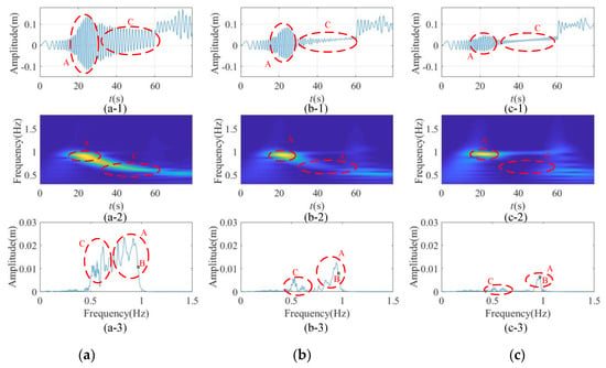
Figure 13.
Time-frequency characteristics of longitudinal response of the bilateral traction system at the descending conveyance with terminal tension and damping cylinder acting on the tensioned pulley: (a) damping = 0; (b) damping = N/s; (c) damping = N/s.
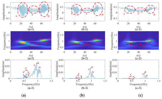
Figure 14.
Time-frequency characteristics of longitudinal response of the bilateral traction system at the tensioned pulley with terminal tension and damping cylinder acting on the tensioned pulley: (a) damping = 0; (b) damping = N/s; (c) damping = N/s.
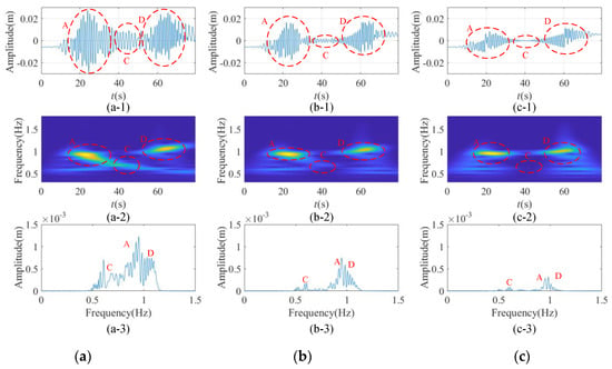
Figure 15.
Time-frequency characteristics of rotation of the tensioned pulley with terminal tension and damping cylinder acting on the tensioned pulley: (a) damping = 0; (b) damping = N/s; (c) damping = N/s.
The dynamical response of the conveyances and tensioned pulley are shown in Figure 12a,b,c-1, Figure 13a,b,c-1, Figure 14a,b,c-1 and Figure 15a,b,c-1. In order to see the influence of bottom damping on the time and frequency domain of vibration characteristics, the continuous wavelet transform and Fourier transform are applied to the dynamic response, which are shown in Figure 12a,b,c-2, Figure 13a,b,c-2, Figure 14a,b,c-2, Figure 15a,b,c-2 and Figure 12a,b,c-3, Figure 13a,b,c-3, Figure 14a,b,c-3 and Figure 15a,b,c-3, respectively. From Figure 12a,b,c-2, Figure 13a,b,c-2, Figure 14a,b,c-2 and Figure 15a,b,c-2, it can be seen that the maximum energy in the running process, which can correspond to the dynamic response which is shown in Figure 12a,b,c-1, Figure 13a,b,c-1, Figure 14a,b,c-1 and Figure 15a,b,c-1, and can obtain the corresponding frequency. By compare the corresponding frequency of Figure 12a,b,c-2, Figure 13a,b,c-2, Figure 14a,b,c-2 Figure 15a,b,c-2 and Figure 12a,b,c-3, Figure 13a,b,c-3, Figure 14a,b,c-3 and Figure 15a,b,c-3, the amplitude corresponding to the frequency of the maximum energy point can be obtained. By comparing Figure 12a,b,c-1, Figure 13a,b,c-1, Figure 14a,b,c-1 and Figure 15a,b,c-1, Figure 12a,b,c-2, Figure 13a,b,c-2, Figure 14a,b,c-2 Figure 15a,b,c-2, Figure 12a,b,c-3, Figure 13a,b,c-3, Figure 14a,b,c-3 and Figure 15a,b,c-3, the same location and frequency of each figure can be marked one by one correspondingly. Here, we mark the region with the largest energy point and mark it uniformly with Zones A, C and D. There is a special point marked in the graph after fast Fourier transform (FFT) transformation, which is set as Point B. This is the excitation frequency of the system at constant speed.
Figure 12 shows time-frequency characteristics of longitudinal response of the traction system at the ascending conveyance. It can be seen that energy concentration points are mainly concentrated in Zone A and Zone C. Zone A is the increase of vibration amplitude caused by the sudden change of running acceleration because the rope is long, and the vibration frequency is about 0.6–0.7 Hz. The increase of amplitude and frequency of Zone C is due to the system’s resonance, and the vibration frequency is about 1–1.1 Hz. Under the same frequency excitation, the vibration frequency in the resonance region is about twice of that in the non-resonance region.
Comparing Figure 12a–c, it can be seen that vibration amplitude of Region A is basically completely dissipated due to the increase of damping. Although the energy of Region C also dissipates, the dissipating speed of that is not as fast as that of Region A, so that the maximum energy region of system changes from Region A to Region C with the increase of damping. It can be seen that the suppressing effect of terminal damping on resonance suppression is not ideal. However, the suppressing effect on the non-resonance region is very strong. In the process of increasing damping, the excitation frequency which is shown as Point B is gradually prominent, so the proportion of its frequency’s amplitude gradually increases.
Figure 13 shows time-frequency characteristics of longitudinal response of the bilateral traction system at the descending conveyance. Energy concentration points are mainly concentrated in Zone A. The increase of amplitude and frequency of Zone A is due to the resonance of the system. Zone C is the non-resonance region. By comparing the time-domain signal with the frequency-domain signal after the FFT transformation, the suppressing effect of terminal damping on Region C is better than that of Region A. Just as the same phenomenon of Figure 12, in the process of increasing damping, the excitation frequency which is shown as Point B is gradually prominent, and the proportion of its frequency’s amplitude gradually increases.
From Figure 12 and Figure 13, it can be concluded that terminal damping has a vibration suppression effect on both resonance and non-resonance regions of dynamical response of ascending and descending conveyance in general. However, the suppression effect of terminal damping on resonance region is not as good as that on non-resonance region. Further, the excitation frequency which is shown as Point B is gradually prominent with the increase of terminal damping. Therefore, as shown in Figure 12a,b,c-3 and Figure 13a,b,c-3 by Fourier transform, when the terminal damping is large enough, the amplitude of the resonance frequency and excitation frequency component will be prominent, and the amplitude of other vibration frequency components will be dissipated, even eliminated. The excitation frequency will also be dissipated, but it will never disappear.
Figure 14 and Figure 15 show time-frequency characteristics of longitudinal response and rotation of the bilateral traction system at the tensioned pulley. In these figures, there are two resonances occurred in the process, which are also the energy concentration point, mainly because they are affected by the longitudinal vibration of both ascending and descending side comprehensively. Comparing Regions A, C and D, the energy is gradually decreasing due to the increase of terminal damping. In Figure 14, it can be seen that the main frequency affecting the longitudinal vibration of the tensioned pulley is the excitation frequency shown as Point B. Just as with the same conclusion in Figure 12 and Figure 13, the resonance frequency and excitation frequency component will be the major components with the increase of terminal damping.
Figure 16 shows the variation of largest amplitude of longitudinal vibration bilateral tensioned traction system along with time. It is evident that the maximum amplitude of the longitudinal vibration of the system decreases with the increase of damping. Especially in resonance C, the resonance amplitude of the system is greatly reduced due to the damping effect, even eliminate resonance.
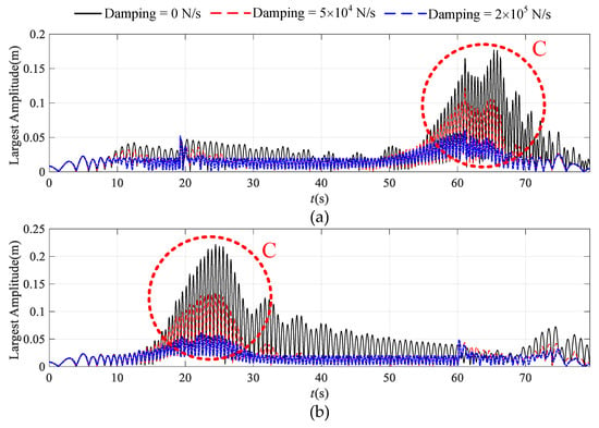
Figure 16.
The variation of largest amplitude of longitudinal vibration of ascending (a) and descending (b) side of tensioned traction system along with time. The black line: damping = 0; the red line: damping = N/s; the blue line: damping = N/s.
Figure 17 is the position statistics of largest amplitude of longitudinal vibration of tensioned traction system. Herein lies the concept. The place where the largest vibration position is called the dangerous section. Further, in order to represent the location of statistics, lifting and compensating ropes are average divided into 100 segments respectively and their positions are dimensionless. Among them, 0 represents the head of the lifting rope, 1 represents the end of compensating rope, 0.5 represents the position where the conveyance sits, and its position is relative. From the following results, almost all dangerous sections are basically concentrated at the head of the lifting rope, the end of the compensating rope and the position of the conveyance. The most dangerous section is at the end of compensating rope, and the secondary hazard section is at the head of the lifting rope. The third place is the conveyance. Caused by damping directly applied to the tensioner where it is closest to the end of compensation rope, it can reduce its proportion as the dangerous section to a certain extent, and the proportion transfer from the end of the compensation rope to the conveyance. However, the end of the compensating rope takes the largest proportion as the dangerous section which won’t change with the variation of terminal damping.


Figure 17.
The position statistics of largest amplitude of longitudinal vibration of tensioned traction system. (a-1,2,3): ascending side with damping = 0, N/s, N/s between tensioned pulley and ground; (b-1,2,3): descending side with damping = 0, N/s, N/s between tensioned pulley and ground.
Figure 18 and Figure 19 shows the transverse displacement of the ascending and descending conveyances. It is evident that adding damping cylinder at the connection between the tensioned pulley and the ground won’t affect the transverse vibration of the bilateral traction system.
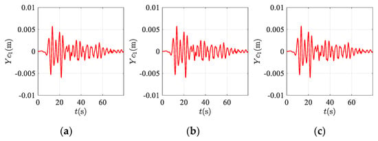
Figure 18.
The transverse response of the bilateral traction system at ascending conveyance with terminal tension and damping cylinder acting on the tensioned pulley: (a) damping = 0; (b) damping = N/s; (c) damping = N/s.
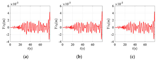
Figure 19.
The transverse response of the bilateral traction system at descending conveyance with terminal tension and damping cylinder acting on the tensioned pulley: (a) damping = 0; (b) damping = N/s; (c) damping = N/s.
In order to obtain the quantitative relationship between the increase of damping and the decrease of vibration amplitude of the system, the response characteristics of tensioned traction systems with different damping are calculated in Figure 20. Here, the damping acting on the tensioned pulley is set from 0 to , and the interval is . The sum of squares of amplitude and standard deviation of the dynamical response of the tensioned system is calculated to reflect the vibration amplitude variation characteristics of the system. Here, the results are the sum of lifting ropes, compensating ropes, tensioned pulley and conveyances. Caused by the transitivity of longitudinal vibration, the vibration of the ropes can be represented by evenly setting discrete points on the rope. By observing the vibration of these points, the vibration of the whole system can be inferred. Here, 100 observation points are placed on the lifting and compensating ropes accordingly.
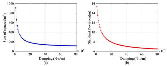
Figure 20.
Sum of squares and standard deviation of amplitude of tensioned system: (a) sum of squares of amplitude; (b) standard deviation of amplitude.
In the above results, it can be seen that increasing damping between tensioned pulley and ground both can suppress the longitudinal vibration of the system. When damping of tensioned pulley is in the interval of 0 − N/s, the sum of squares and standard deviation of the vibration’s amplitude of the tensioned system is decreased rapidly. When damping of tensioned pulley is in the interval of − N/s, the decrease rate of sum of squares and standard deviation of vibration’s amplitude is obviously reduced. When the damping is very large, with the increase of damping, the variance and square sum of the system basically have no change. It can be seen that there is not a linear relationship between the increase of damping of damping cylinder and the decrease of vibration amplitude. The results show that the amplitude of system decreases exponentially with the increase of the terminal damping acting on tensioned pulley.
3.3. Discussion on Different Running Speed of Traction System
During the operation of bilateral tensioned system, different running speed will produce different dynamical response. Figure 21, Figure 22, Figure 23 and Figure 24 shows the longitudinal response of ascending and descending conveyances and tensioned pulley under different running speed. The black, red, green line stand for the system of running speed is 12 m/s, 13.66 m/s, 15 m/s. From the perspective of dynamic response, it can be seen that the resonance positions of the system are also different with the different running speed. However, with the increase of the system speed, it is found that the overall amplitude of the longitudinal response of conveyances and tensioned pulley is decreasing, especially in the resonance region, which even will eliminate resonance phenomenon of the system. Therefore, running speed of the system is not positively related to the vibration amplitude of the system, even in a negative proportion.
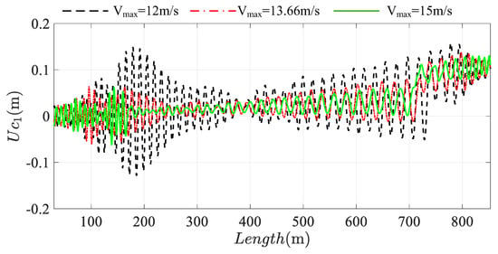
Figure 21.
The longitudinal response of the bilateral traction system at the ascending conveyance. The black line: Vmax = 12 m/s; the red line: Vmax = 13.66 m/s; the green line: Vmax = 15 m/s.
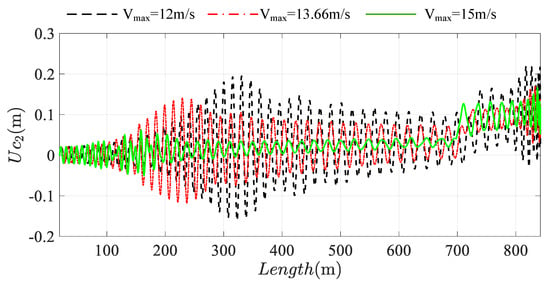
Figure 22.
The longitudinal response of the bilateral traction system at the descending conveyance. The black line: Vmax = 12 m/s; the red line: Vmax = 13.66 m/s; the green line: Vmax = 15 m/s.
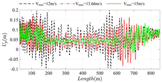
Figure 23.
The longitudinal response of the bilateral traction system at the tensioned pulley. The black line: Vmax = 12 m/s; the red line: Vmax = 13.66 m/s; the green line: Vmax = 15 m/s.
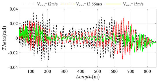
Figure 24.
The rotation vibration of tensioned pulley. The black line: Vmax = 12 m/s; the red line: Vmax = 13.66 m/s; the green line: Vmax = 15 m/s.
This is a strange phenomenon. The faster the speed is, the smaller the amplitude is. The slower the speed is, the more violent the vibration is, and the larger the amplitude is. The reason can be obtained through the frequency chart, as shown in Figure 25. This is because the running speed will affect the excitation frequency, and the change of excitation frequency will have a huge impact on the vibration response of the system. When the excitation frequency is close to the natural frequency of the system, there will be resonance in the system, and the vibration amplitude will also increase significantly. Therefore, the change of system operation speed is positively related to the excitation frequency, which affects the relationship between the excitation frequency and the natural frequency, and then affects the response change of the system. Therefore, it is not that the smaller the speed of the system, the smaller the vibration amplitude of the system.
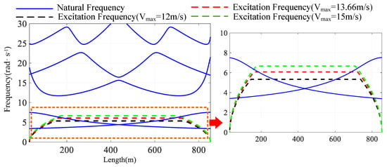
Figure 25.
Variation of longitudinal natural frequency and excitation frequency comparison under different running speed Vmax. The black line: Vmax = 12 m/s; the red line: Vmax = 13.66 m/s; the green line: Vmax = 15 m/s.
4. Conclusions
In this paper, the complete mathematical model of bilateral traction system is established based on Hamilton’s principle, which takes into account the transverse and longitudinal coupling effect of ropes. The governing equations and boundary conditions are obtained. From the results, it is evident that when the compensating rope is in tensioned state, the amplitudes of longitudinal and transverse vibration of ropes and conveyances will be much smaller than that of traditional traction system when the compensating rope is in free suspended state. Further, and considering that the length of lifting rope and compensating rope is complementary, the veering phenomena appears in the frequency of each order. Two tensioned methods are discussed. From the results, it is found that the terminal tension acting on compensating rope can only change the static displacement of ropes, which won’t change the dynamical displacement. Besides, setting damping cylinder between tensioned pulley and ground can suppress the longitudinal vibration and rotation vibration of the tensioned bilateral traction system. Especially at the resonance region, the increase of the damping’s value can even eliminate longitudinal resonance region. When the terminal damping is large enough, the amplitude of the resonance frequency and excitation frequency component will be prominent, which can be proven by continuous wavelet transform (CWT) and FFT.
The amplitude of system decreases exponentially with the increase of the terminal damping acting on the tensioned pulley, which is a non-linear relationship. Except that, different running speed of tensioned traction system is discussed. It can be seen that the magnitude of vibration amplitude of tensioned traction system is not necessarily proportional to the magnitude of the velocity, but rather, inversely proportional. The prediction can then inform the development of relevant mitigating strategies to minimize the effects of excessive vibrations and improve ride quality.
Author Contributions
Methodology, L.W.; funding acquisition, G.C.; investigation, L.W.; data analysis, L.W., Y.Z. and N.W.; writing—original draft L.W.; writing—review and editing, L.W. and N.W. All authors have read and agreed to the published version of the manuscript.
Funding
This research was funded by the Fundamental Research Funds for the Central Universities (2017XKQY038) and the Priority Academic Program Development of Jiangsu Higher Education Institutions (PAPD).
Conflicts of Interest
The authors declare no conflicts of interest.
Nomenclature
| Length of lifting and compensating ropes | Damping between tensioned pulley and ground | ||
| Velocity of lifting and compensating ropes | Preload working on tensioned pulley | ||
| Acceleration of lifting and compensating ropes | Connecting point between the lifting(compensating) ropes and conveyances | ||
| Total lifting height | Stiffness between conveyances and guide rails | ||
| Coordinate measurement of the lifting rope and compensating ropes | Damping between conveyances and guide rails | ||
| Tangent points between the compensating ropes and tensioned pulley | Longitudinal interaction forces between the conveyances and lifting(compensating) ropes | ||
| () | Mass and moment of inertia of tensioned pulley | Transverse interaction forces between the conveyances and lifting(compensating) ropes | |
| Radius of the tensioned pulley | Interaction forces between the tensioned pulley and compensating ropes | ||
| Longitudinal vibration of conveyances | Transverse vibration of conveyances | ||
| Longitudinal vibration of ropes | Transverse vibration of ropes | ||
| Longitudinal vibration of tensioned pulley | Rotation vibration of tensioned pulley |
Appendix A
The tensions at arbitrary positions along the lifting, compensating, and guiding ropes are calculated as follows:
Appendix B
The virtual work done by the interaction force can be written as:
where, , and are the reacting force of , and . According to the third law of Newton’s law, the interaction force meets the following condition:
Appendix C
The Specific expressions of generalized transverse force , are derived as follows:
Appendix D
The trial functions [28] can be set as follows:
Appendix E
The matrices and force vectors for the tensioned traction system are defined in the following forms:
The specific forms of the elements in matrices , , , , , , , , and are defined as follows:
where, ,
where, , .
References
- Li, J. Dynamics of Electric Pulley Conveying Cableway System in Banana Plantation. Nongye Jixie Xuebao/Trans. Chin. Soc. Agric. Mach. 2013, 44, 211–216. [Google Scholar]
- Feng, H.; Zhou, C.; Zhou, X.; Zhilong, W.U. Bouncing vibration response analysis of the cargo unhooking of single span aerial cableway. Mech. Eng. 2014, 36, 190–194. [Google Scholar]
- Pi, Y.; Ouyang, H. Vibration control of beams subjected to a moving mass using a successively combined control method. Appl. Math. Model. 2016, 40, 4002–4015. [Google Scholar] [CrossRef]
- Liu, Y.; Fang, G.; Xiuyu, H.; Qing, H. Boundary Control for an Axially Moving System with Input Restriction Based on Disturbance Observers. IEEE Trans. Syst. Man Cybern. Syst. 2018, 49, 1–12. [Google Scholar] [CrossRef]
- Nguyen, Q.C.; Hong, K.-S. Transverse Vibration Control of Axially Moving Membranes by Regulation of Axial Velocity. IEEE Trans. Control Syst. Technol. 2011, 20, 1124–1131. [Google Scholar] [CrossRef]
- Kaczmarczyk, S.; Ostachowicz, W. Transient vibration phenomena in deep mine hoisting cables. Part 1: Mathematical model. J. Sound Vib. 2003, 262, 219–244. [Google Scholar] [CrossRef]
- Kaczmarczyk, S.; Ostachowicz, W. Transient vibration phenomena in deep mine hoisting cables. Part 2: Numerical simulation of the dynamic response. J. Sound Vib. 2003, 262, 245–289. [Google Scholar] [CrossRef]
- Cao, G.H.; Wang, J.J.; Zhu, Z.C. Coupled vibrations of rope-guided hoisting system with tension difference between two guiding ropes, ARCHIVE Proceedings of the Institution of Mechanical Engineers Part C. J. Mech. Eng. Sci. 2018, 232, 231–244. [Google Scholar] [CrossRef]
- Wang, J.J.; Cao, G.H.; Zhu, Z.C. Lateral and torsional vibrations of cable-guided hoisting system with eccentric load. J. Vibroengineering 2016, 18, 3524–3538. [Google Scholar]
- Bao, J.H. Dynamics Modeling and Vibration Control of High-Speed Elevator Hoisting System; Shanghai Jiao Tong University: Shanghai, China, 2014. [Google Scholar]
- Bao, J.H.; Zhang, P.; Zhu, C.M. Modeling and control of longitudinal vibration on flexible hoisting systems with time-varying length. Procedia Eng. 2011, 15, 4521–4526. [Google Scholar]
- Bao, J.H.; Zhang, P.; Zhu, C.M.; Zhu, M.; Jin, L.Q.; Xie, H.X. Vibration control of high-speed elevator hoisting systems based on tensioning devices. J. Vib. Shock 2017, 36, 221–226. [Google Scholar]
- Zhang, P. Theoretic and Test Research on Dynamic Behaviors of High-Speed Elevator Suspended System; Shanghai Jiao Tong University: Shanghai, China, 2007. [Google Scholar]
- Arrasate, X.; Kaczmarczyk, S.; Almandoz, G.; Abete, J.M.; Isasa, I. The modelling, simulation and experimental testing of the dynamic responses of an elevator system. Mech. Syst. Signal Process. 2014, 42, 258–282. [Google Scholar] [CrossRef]
- Zhu, W.D.; Ren, H. An Accurate Spatial Discretization and Substructure Method with Application to Moving Elevator Cable-Car Systems—Part I: Methodology. J. Vib. Acoust. 2013, 135, 051036. [Google Scholar] [CrossRef]
- Arnold, M.; Brüls, O. Convergence of the generalized- α scheme for constrained mechanical systems. Multibody Syst. Dyn. 2007, 18, 185–202. [Google Scholar] [CrossRef]
- Brüls, O.; Arnold, M. The Generalized-α Scheme as a Linear Multistep Integrator: Toward a General Mechatronic Simulator. J. Comput. Nonlinear Dyn. 2018, 3, 041007. [Google Scholar] [CrossRef]
- Brüls, O.; Golinval, J.C. On the numerical damping of time integrators for coupled mechatronic systems. Comput. Methods Appl. Mech. Eng. 2008, 197, 577–588. [Google Scholar] [CrossRef]
- Brüls, O.; Golinval, J.C. The generalized-α method in mechatronic applications, ZAMM. J. Appl. Math. Mech. 2010, 86, 748–758. [Google Scholar]
- Otsuki, M.; Ushijima, Y.; Yoshida, K.; Kimura, H.; Nakagawa, T. Application of Nonstationary Sliding Mode Control to Suppression of Transverse Vibration of Elevator Rope Using Input Device with Gaps. JSME 2006, 49, 385–394. [Google Scholar] [CrossRef][Green Version]
- Wang, N.; Cao, G.; Yan, L.; Wang, L. Modeling and Control for a Multi-Rope Parallel Suspension Lifting System under Spatial Distributed Tensions and Multiple Constraints. Symmetry 2018, 10, 412. [Google Scholar] [CrossRef]
- Wang, L.; Cao, G.; Wang, N.; Yan, L. Modeling and Dynamic Behavior Analysis of Rope-Guided Traction System with Terminal Tension Acting on Compensating Rope. Shock Vib. 2019, 2019, 24. [Google Scholar] [CrossRef]
- Crespo, R.S.; Kaczmarczyk, S.; Picton, P.; Su, H. Modelling and simulation of a stationary high-rise elevator system to predict the dynamic interactions between its components. Int. J. Mech. Sci. 2018, 137, 24–45. [Google Scholar] [CrossRef]
- Watanabe, S.; Okawa, T.; Nakazawa, D.; Fukui, D. Vertical vibration analysis for elevator compensating sheave. J. Phys. Conf. Ser. 2013, 148, 012007. [Google Scholar] [CrossRef]
- Zhu, W.D.; Ni, J. Energetics and Stability of Translating Media with an Arbitrarily Varying Length. J. Vib. Acoust. 2000, 122, 295–304. [Google Scholar] [CrossRef]
- Wu, J.; Kou, Z.-M.; Liang, M. Transverse dynamics analysis of rope in multi-rope friction hoisting system. J. Vib. Shock 2016, 35, 184–188. [Google Scholar]
- Chang, Y. Study on Health Status Monitoring System of Multi Rope Friction Hoisting System; China University of Mining and Technology: Xuzhou, China, 2017. [Google Scholar]
- Ren, H. Accurate Simulation of the Dynamics of Elevator Systems; University of Maryland, Baltimore County: Baltimore, MD, USA, 2011. [Google Scholar]
© 2020 by the authors. Licensee MDPI, Basel, Switzerland. This article is an open access article distributed under the terms and conditions of the Creative Commons Attribution (CC BY) license (http://creativecommons.org/licenses/by/4.0/).