1. Introduction
Centrifugal pumps play a key role in the industry, irrigation, and water supply engineering. With the application of large-scale centrifugal pumps in production lines more and more widely, the operating stability of pumps has become an increasingly important issue. At the designed flow rate, the flow field inside the rotating impeller passages is axisymmetric. The impeller-volute interaction in pumps can cause periodic pressure fluctuations, which are typical unsteady characteristics propagating through the flow passage components. However, at low flow rates, this axisymmetric flow field would be destroyed, and then some rare pressure fluctuations excited by stall cells appear. It always induces intensified vibration, enhanced noise, and decreased capacity of water supply, which seriously affects the safe and stable operation of the pump system [
1,
2,
3].
A lot of works have been devoted to analyze the generation and transmission of pressure fluctuations through such pumps [
4,
5,
6,
7]. Chu S et al. [
8,
9] considered that impeller-volute interaction of centrifugal pumps is the main source of pressure fluctuation. But when the pumps operated at low flow rates, the stall occurred and the flow field near volute tongue varied dramatically, where the flow was reversed around the leading edge of volute tongue. Furthermore, stall cells in the impellers always cause rotating stall, which have a great effect on pressure fluctuations [
10,
11]. Under low flow rates, Zhang N et al. [
12] discovered that stall cells in the impeller would lead to the low frequency of pressure fluctuations in the volute inducing the high vibration. Kaupert K et al. [
13] and Gonzalez J et al. [
14] also discovered pressure fluctuation amplitude of volute tongue increased under low flow rates and the more the flow rate moved, the higher the amplitude is. Braun O et al. [
15,
16] studied the double-suction centrifugal pump based on the numerical simulation and experiment method, and it showed that stall cells occur in diffuser, resulting in that the amplitudes are 2 times larger than that under unstall condition. Yao Z et al. [
17] analyzed the pressure fluctuations around the volute tongue and found a broadband frequency which was consistent with the dominant frequency of the vibration on pumps. Wang H et al. [
18] also studied the pressure fluctuations at low flow rates and detected rotating stall cells in diffuser vane, which made the pressure fluctuations increase greatly. Zhou P et al. [
19,
20] revealed stall cell structures in a single centrifugal pump impeller, and found that the large vortex at the outlet induced by stall cell had an obvious life cycle with a low frequency including decay, split, mergence and growth.
Above all, under stall conditions, pressure fluctuations of centrifugal pump resulted from the combined effect of stall cells and impeller-volute interaction. However, it’s rare to see reports about pressure fluctuations under stall condition. The current work aims to calculate the internal flow field of the centrifugal pump under different stall conditions based on Large Eddy Simulation (LES). This study focuses on the impeller-volute interaction under stall conditions around the tongue district, thus providing a reference for stable operation of centrifugal pump units.
2. The Investigated Pump and Simulation Details
The particularity and complexity of the internal flow present higher requirements for numerical simulation method when rotating stall occurs in the pump impeller. Therefore, Large Eddy Simulation model of dynamic SGS (Subgrid Scale) is used to calculate internal flow inside the pump, which has a good accuracy for predicting the rotating stall phenomenon [
21]. Specific formulas are derived as follows:
The incompressible form of LES governing equations can be obtained by applying a filter (overbar) to Navier-Stokes (N-S) and continuity equations [
22]:
where, the overbar is the spatial filtering called the grid-scale filter.
represents the resolved velocity component,
is the resolved pressure,
is the kinematic viscosity,
is the density,
is the body force term and
is the SGS stress tensor. It can be defined as:
The stress term of the SGS can be computed as
where
is the resolved strain rate tensor and the SGS stress viscosity
is given by
where the over-bar represents the spatial filter ring for a filtered size
,
is the dynamic Smagorinsky coefficient and
is the magnitude of
.
The investigated pump consists of a low specific-speed centrifugal impeller and a volute, which has been tested by Johnson D et al. [
23]. Laser Doppler Velocimeter (LDV) was applied to the pump and the stall phenomenon was detected under low flow rate. The design flow rate is
Qd = 3.0 L/s and its head is
Hd = 2.36 m. The simulation for the off-design condition was performed using ANSYS Fluent. The blade inlet angle is
= 19.7° and the outlet angles is
= 18.7°. More detailed geometry parameters and experimental data are available in reference [
23].
In consideration of the effect of non-fully developed flow on the simulation accuracy, the inlet and outlet of the pump were extended appropriately. The computational domain included the impeller, the volute case and the extension of the inlet and outlet. Due to the complex computational domain, the unstructured hexahedral and tetrahedral hybrid mesh was employed for its fine adaptability. The mesh was refined locally in the near-wall regions with respect to the requirement of LES. The mesh sensitivity analysis was carefully carried out. Four different meshes were considered to compare the head and efficiency at
Qd, as seen in
Table 1. Considering the accuracy requirements and the computer resources, a mesh of totally 4.37 million elements was selected as the optimal adjustment. Increasing the element number didn’t show significant change on the head and efficiency during the mesh sensitivity analysis. The mesh quality can satisfy the requirements of calculation, as shown in
Figure 1.
The rotation reference frame is considered for the flow passage, and the rotating speed is set to the rotation speed of the impeller. The boundary condition of the inlet velocity is determined by the flow rate, which contains some fluctuation components perpendicular to the inlet boundary. The value of pressure is given at the outlet of the passage. The time step is set as 0.00023 s that corresponds to the global Courant number estimation of less than 1 and the maximum of less than 10, i.e., overall 360 time steps per impeller revolution. The residual convergence criterion for each time step is reduced to within 15 iterations per time step. Generally, the simulation should contain about 40 revolutions, so that we can always get a better result.
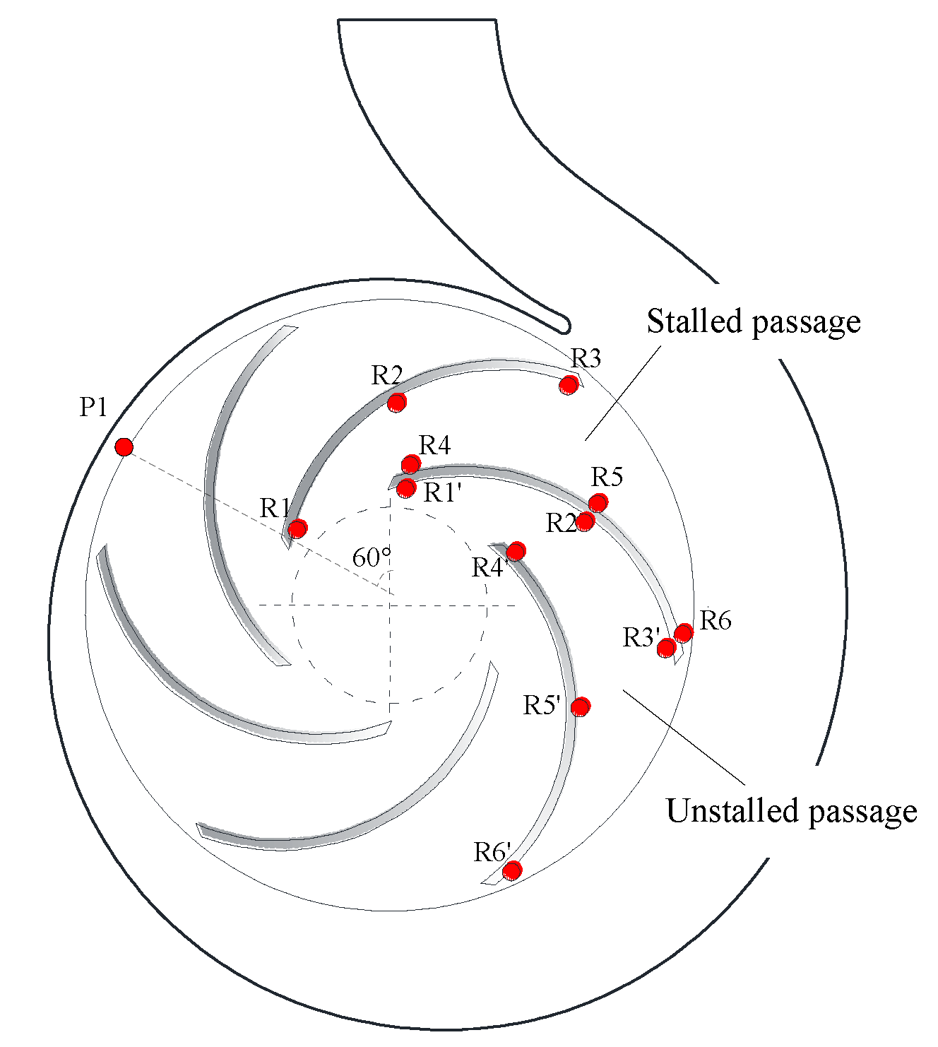
Figure 2 shows locations of monitoring points, and monitoring points are arranged in the mid-span plan of the pump, which are named as R1–R6 alone the blade in the stalled passage and R1′–R6′ in the unstalled one. Another monitoring point P1 is arranged on the volute surface according to the reference [
23]. During the calculation, the pressure fluctuation histories of the monitoring points were recorded.
3. Prediction for Stall Point of the Centrifugal Pump
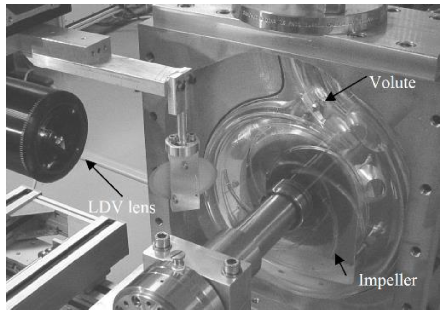
Figure 3 shows the perspex centrifugal volute pump model. More detailed geometry and experimental data is available in reference [
23]. The comparison between simulation and test data is presented in
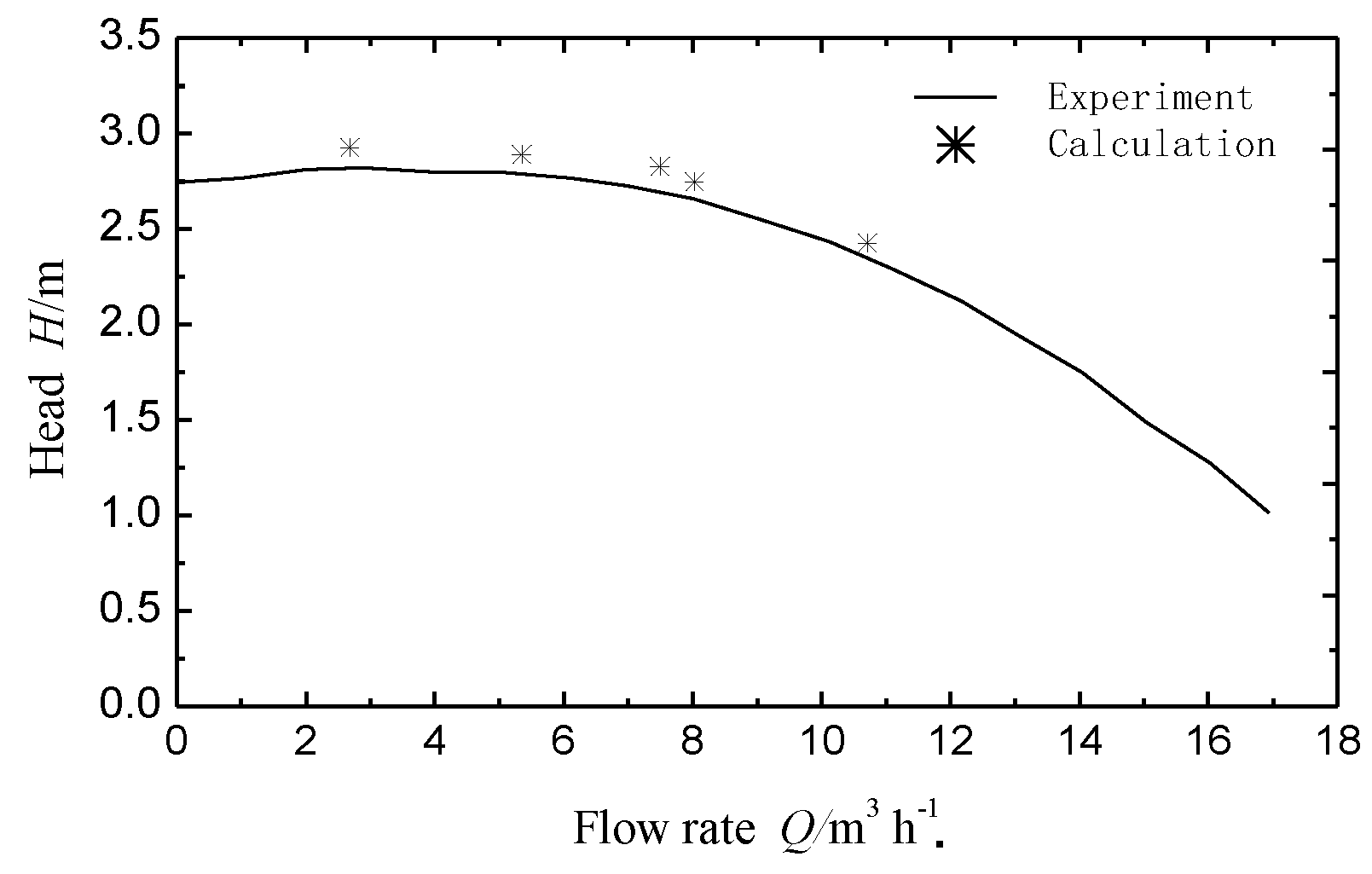
Figure 4. It can be seen that the predicted head agrees well with the experiment. Although the predicted value is slightly higher, the maximum deviation with the experimental value is almost 8%. It is because of the assumption of the smooth wall and out of consideration for the side chamber in the numerical simulation.
In order to predict stall point, the inlet velocity was decreased from the designed flow rate
Qd. The stall phenomenon always accompanies the large flow vortex, so the Z-vorticity zone with lower negative was taken to characterize the stall cell [
24]. As shown in
Figure 5, the deep blue region near the suction side of blade represents the stall cell. Seen from the
Figure 5d, at 0.75
Qd, the Z-vorticity distribution in each passage seems similar. The flow field inside the impeller passages is axisymmetric. However, with the flow rate decreasing, the axisymmetric flow field is destroyed by stall cells. The blocked passage and the unblocked passage occur alternately in the impeller. As the flow rate is further reduced, the size of the stall cell gradually increases, and the difference of the pressure distribution in the stalled and unstalled passage also increases. In this paper, the flow rate less than 0.70
Qd was considered as the stall condition. So 0.70
Qd was the critical flow rate. At this point, the attack angle was 5.6° which can be calculated by velocity triangle rule [
25]. Unstall conditions (1.0
Qd and 0.75
Qd), as well as the stall conditions (0.70
Qd, 0.5
Qd and 0.25
Qd), are selected for the simulation.
To further validate the simulation method under stall condition, the comparison of frequency spectra between measured results and simulation at 0.25
Qd was investigated. The Fast Fourier Transform (FFT) method was used for the spectrum analysis. All the obtained frequencies were normalized by the impeller rotating frequency (6
fr). The transient pressure fluctuations are presented using pressure coefficient, which can be obtained by the formula
The comparison of frequency spectra at monitoring point P1 at 0.25
Qd is shown in
Figure 6. The main dominant frequencies at the monitoring point P1 are identical between the experiment and simulation. The first dominant frequency is 3
fr, which is 50% of the blade passage frequency (6
fr). Obviously, it is induced by the alternated stall phenomenon. The second dominant frequency is the blade passage frequency, which is caused by the impeller-tongue interaction. However, their amplitude values still have some difference. It’s possible that the actual pressure fluctuations in the pumps are induced by the overall results of hydraulic, mechanical and electrical factors, whereas the simulation results only take into account the hydraulic factors [
26].
4. Unsteady Behavior of Stall Cells
Hunt et al. formulated the
Q-criterion assuming incompressible flow. In this case,
Q is a measure of the local rotation rate in excess of the strain rate [
27]:
where
is the angular rotation rate tensor and
is the strain rate tensor.
Q > 0 defines a vortex as a region where there is more rotation than stretching.
Q-criterion has been successfully applied to identify the vortex in the centrifugal pump impeller [
4].
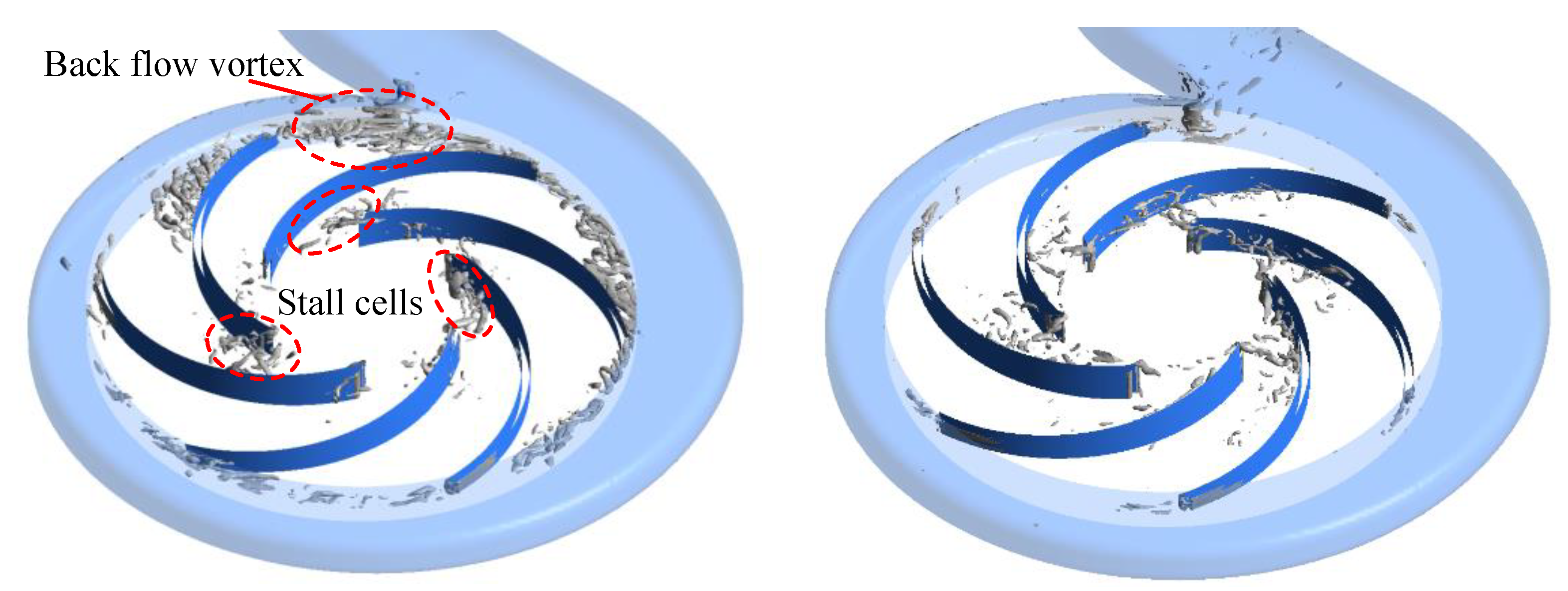
Figure 7 shows the instantaneous vortex structures in the impeller using an iso-surface of the
Q-criterion. At 0.25
Qd, it can be seen that three large-scale stall cells alternately locate at the entrance of passages. In addition, the back flow vortex appears in each passage. The nearer the passage gets to the volute tongue, the larger the vortex area is. However, at 0.75
Qd, there is no stall cell in the passage. Some small-scale vortex appears in the passage due to the flow separation at low flow rate. The back flow vortex doesn’t appear in each passage. It indicates that the volute tongue has little effect on the back flow vortex at 0.75
Qd.
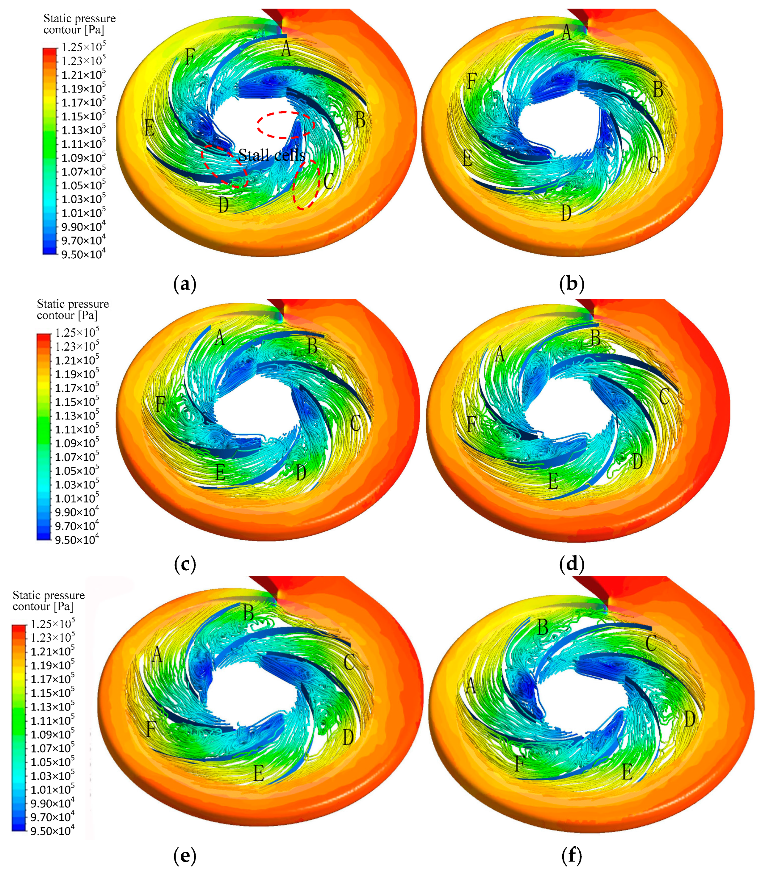
In order to reveal the evolution of flow structures over time, the instantaneous 3D streamlines inside the pump during double blade passing cycles are shown in
Figure 8a–f. At 0.70
Qd, 0.5
Qd and 0.25
Qd, the motions of stall cells are similar, so 0.25
Qd is chosen to analyze the internal flow of centrifugal pump. Note that the color shows the static pressure distribution.
Figure 8a–c are the duration of unstalled passage passing tongue-region.
Figure 8d–f are the duration of stalled passage passing tongue-region. A~F refer to different impeller passages.
Obviously, the static pressure distributions in the impeller are similar. Three stall cells are located at the inlet of the passage alternately. The unstalled passage A and stalled passage B are taken as an example to analyze the influence of impeller-tongue interaction on stall cells. At
t = 0, the reverse pressure gradient in passage A is large. As the impeller rotates, it reduces. At
t = 1/3
T, a local low pressure zone occurs at the passage inlet. At
t = 2/3
T, the pressure gradient of the suction side of blade Suction side near the passage exit is the largest, and a low pressure zone appears, where the flow separation is induced easily. At
t =
T, the passage A completely turns around the tongue. At this point, the reverse pressure gradient from the inlet to outlet is the lowest, and the local low pressure zone also disappears.
Figure 8d–f illustrate the change of pressure distribution in passage B as the impeller rotates. It can be seen that, due to the influence of stall cell, the reverse pressure gradient in passage B is larger than that in the passage A. The shape of the stall cell changes with the impeller rotates. From
t =
T to
t = 5/3
T, the size of the stall cell increases. There is a more obvious low pressure zone in the blade pressure surface near the passage outlet.
t = 2
T, the passage B completely turns round the tongue. The flow filed is similar with the passage F at
t = 0. As the inverse pressure gradient decreases suddenly, the size of the stall cells decreases.
5. Analysis of Pressure Fluctuations in the Impeller
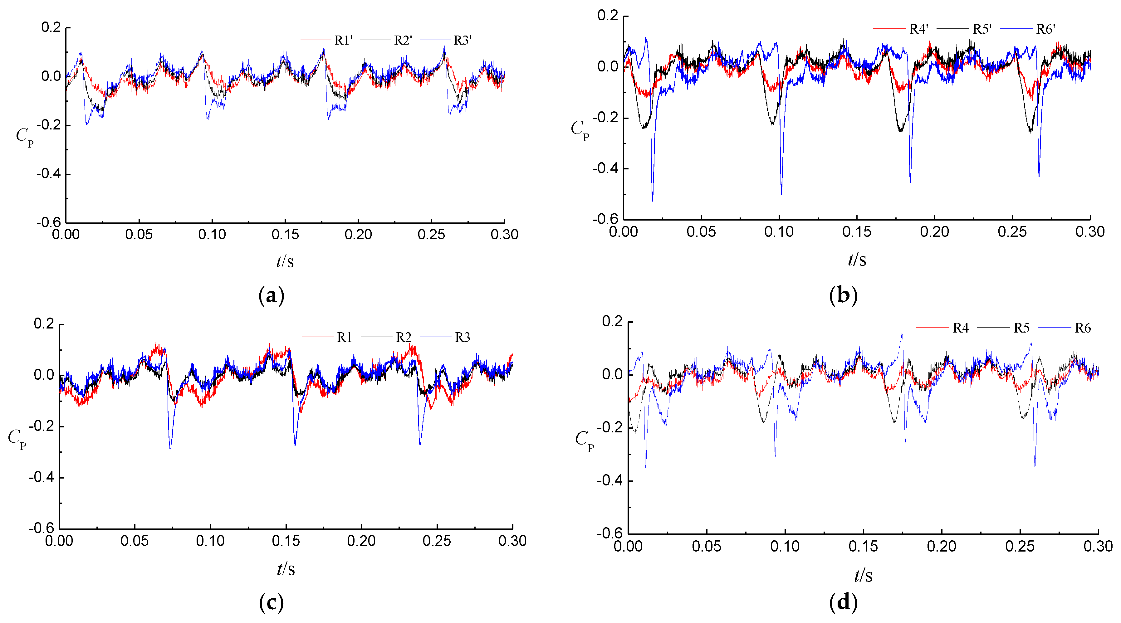
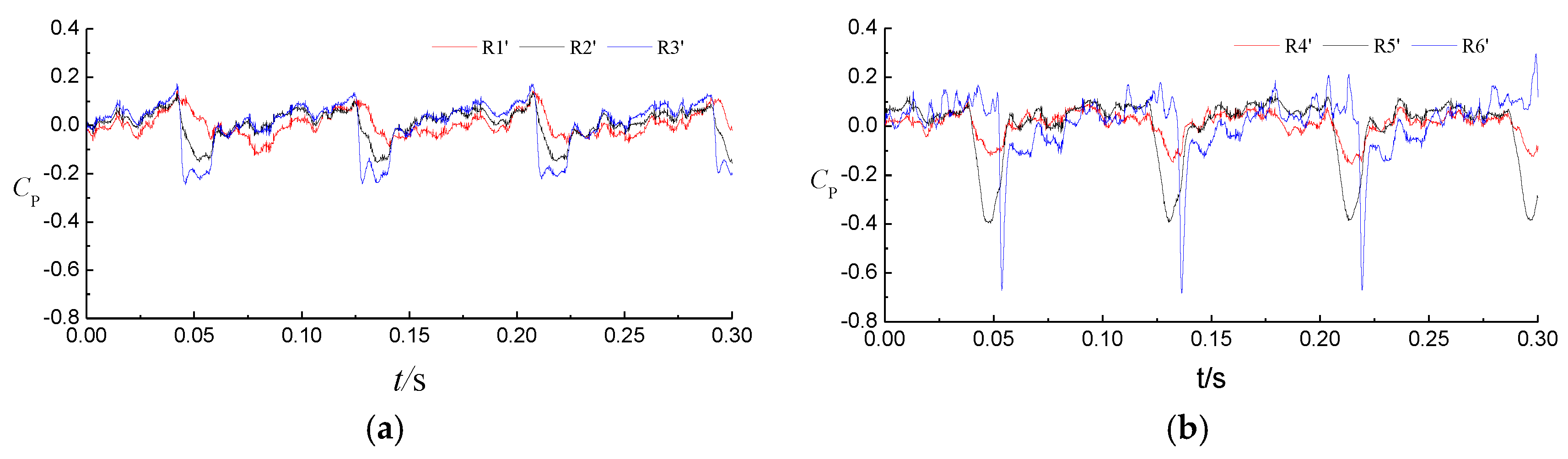
Figure 9 shows the time history of the pressure coefficient fluctuation of monitoring points in the stalled or unstalled passages under stall conditions. As seen from the
Figure 9, the pressure fluctuation signals are obviously periodic. The pressure fluctuations at the impeller tips are stronger than these at the other locations due to the impeller-volute interaction. As each blade tip passes the tongue, the tip flow is changed suddenly, which induces a low pressure zone at the exit of the passage. The pressure at upstream measuring points is also decreased, but the change is relatively smooth. The variation of pressure fluctuation amplitude in unstalled passage is significantly less than that in stalled passage. However, for the suction side of blade, the amplitude changes little. As shown in
Figure 9 and
Figure 10, the peak-to-peak value of pressure fluctuation at 0.25
Qd is obviously greater than that at 0.5
Qd.
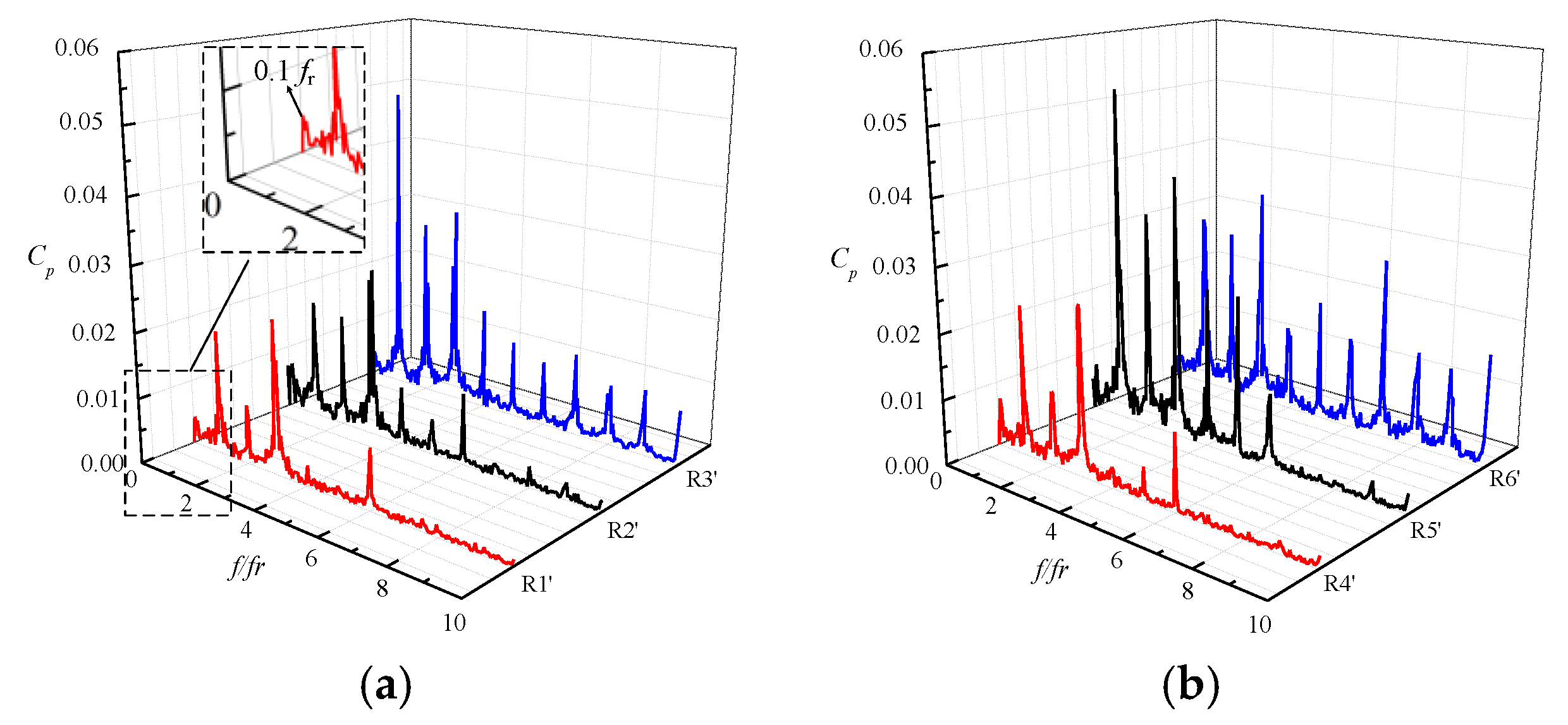
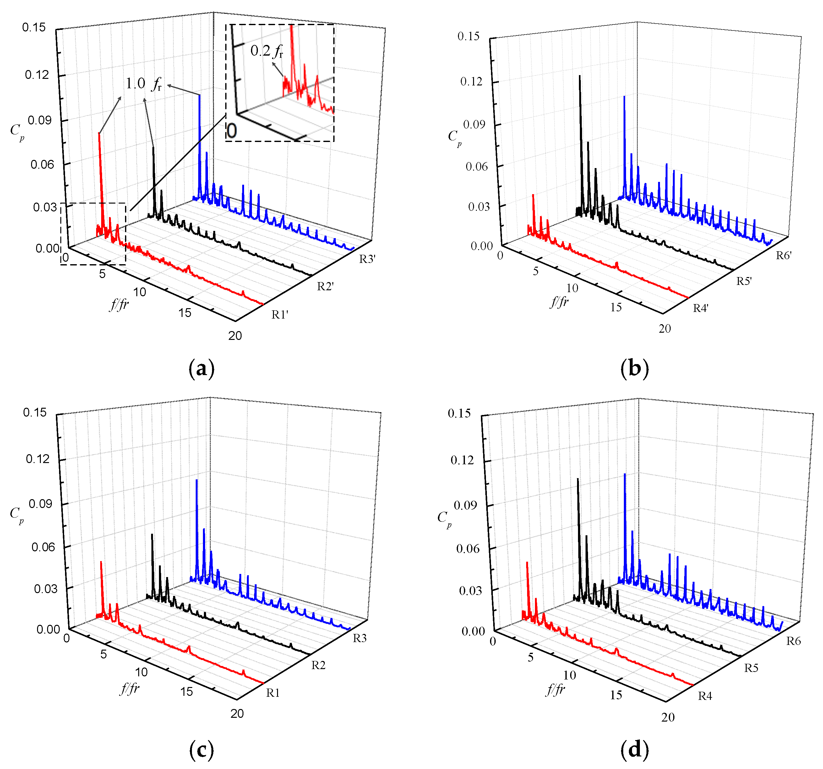
Pressure coefficient fluctuations on monitoring points located at the stalled or unstalled passage were obtained. The frequency spectra of pressure coefficient fluctuations on monitoring point R1′ at 0.25
Qd can be seen in
Figure 11a. The dominant frequencies are composed of the rotating frequency and its higher harmonics. The first dominant frequency is 1.0
fr. In addition, a low frequency 0.2
fr can be detected, and its amplitude is relatively insignificant. Compared with the previous research on the single impeller without the volute casing [
19], it illustrates that the low frequency 0.2
fr caused by the stall cell shedding is weakened while the impeller-volute interaction plays a leading role in the flow field. For the unstalled passage, as seen in
Figure 11c,d, the dominant frequency of the monitoring points on the blade is also
fr. The amplitude increases gradually from the inlet to outlet. The impeller-volute interaction around the tongue region plays a leading role under the low flow rate. The further distance apart from the tongue, the greater the impact is. However, for the stalled passage, the pressure fluctuation amplitude of R1′ point is stronger than that of R4′ point. Because stall cells locate at the suction side, which are close to R4’ point. The stall cells are influenced by the uneven circumferential pressure distribution of the volute casing, and have the periodical variation. The stall cell impact greatly on R1′ point, so the pressure fluctuation amplitude is also stronger. For R4′ point located at the pressure side of blade, which was influenced little by the stall cell, its pressure fluctuation amplitude is low. However, because the vortex downstream stalled passage is attached to the pressure side, and vortex core is near R5′ point. The vortex is very unstable due to the effect of the tongue. Therefore, the pressure fluctuation amplitude of R5′ point is stronger than that of R2′ point at Suction side.
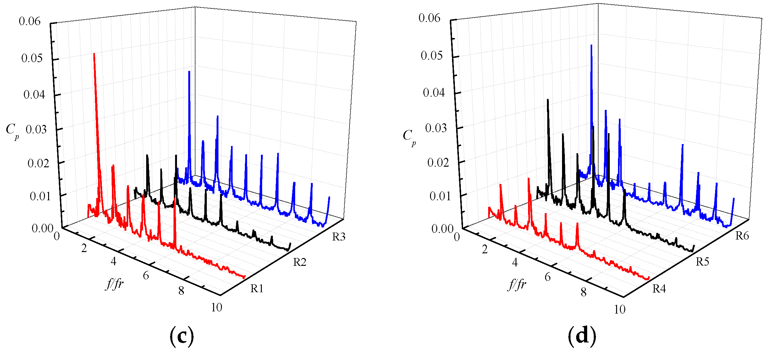
Seen from
Figure 12, operation at 0.5
Qd, the distribution of pressure fluctuation frequency domain is similar, the dominant frequencies are the rotating frequency or their higher harmonics. However, their amplitudes are relatively small, which are almost 50% of that at 0.25
Qd. A low frequency 0.1
fr can be detected, and it indicates that the flow rate has a great effect on the low frequency.
Although monitoring points R3, R3′, R6, and R6′ on the blade tip are close to point P1 on the volute casing, the dominant frequency amplitudes of points R3, R3′, R6, and R6′ are obviously larger than the amplitude of point P1. It is because that the sources of their dominant frequencies are different. Seen from the
Figure 8, the first dominant frequency of R3, R3′, R6, and R6′ is 1.0
fr, which is induced by the blades interacting with the volute tongue. However, the first dominant frequency of the point P1 is 3.0
fr, which is induced by the rotating blade. As shown in
Figure 11, the internal flow in the impeller passages greatly changes when the passage turning round the volute tongue. The static pressure on the volute changed smoothly. So the induced pressure fluctuations on the blades are greater than on the volute at low flow rates.
6. Conclusions
The internal flow in a volute-type centrifugal pump under stall conditions was investigated using large eddy simulation method. A comparison of the pressure fluctuation and head curve showed a good agreement between the unsteady simulation and experiment. Conclusions can be drawn as follows:
(a) The volute tongue has large effect on the back flow vortex under stall condition. The nearer the passage gets to the volute tongue, the larger the vortex area is. However, the back flow vortex disappears in each passage under unstall conditions.
(b) In flow pattern analysis, it is found that rotating stall occurs when the flow rate drops to 0.70 Qd. Three stall cells have be observed at the entrance of impeller passages, which remain stationary relative to the rotating impeller. As the flow rate decreases, the area occupied by stall cells gradually increases. The peak-to-peak values of pressure fluctuations at 0.25 Qd are obviously larger than that at 0.5 Qd.
(c) The dominant frequencies of the pressure fluctuations on the blades are the rotating frequency or their higher harmonics, which indicates the impeller-volute interaction played a leading role for the unstalled or stalled passage. For the stalled passage, the amplitude of the low frequency induced by stall cell is relatively insignificant.

 ,
, 


