Article

Reliability-Aware Cooperative Routing with Adaptive Amplification for Underwater Acoustic Wireless Sensor Networks

1
Department of Electronics, University of Peshawar, Peshawar 25120, Pakistan
2
Faculty of Computing and Information Technology, Northern Border University, Rafha 76321, Saudi Arabia
3
Department of Computer System and Technology, Faculty of Computer Science and Information Technology, University of Malaya, Kualalumpur 50603, Malaysia
*
Authors to whom correspondence should be addressed.
Symmetry 2019, 11(3), 421; https://doi.org/10.3390/sym11030421
Submission received: 24 February 2019 / Revised: 18 March 2019 / Accepted: 19 March 2019 / Published: 22 March 2019

Abstract

:
The protocols in underwater acoustic wireless sensor networks (UAWSNs) that address reliability in packets forwarding usually consider the connectivity of the routing paths up to one- or two-hops. Since senor nodes are connected with one another using other nodes in their neighborhood, such protocols have compromised reliability. It is because these protocols do not guarantee the presence of neighbors beyond the selected one- or two-hops for connectivity and path establishment. This is further worsened by the harshness and unpredictability of the underwater scenario. In addition, establishment of the routing paths usually requires the nodes’ undersea geographical locations, which is infeasible because currents in water cause the nodes to move from one position to another. To overcome these challenges, this paper presents two routing schemes for UAWSNs: reliability-aware routing (RAR) and reliability-aware cooperative routing with adaptive amplification (RACAA). RAR considers complete path connectivity to advance packets to sea surface. This overcomes packets loss when connectivity is not established and forwarder nodes are not available for data routing. For all the established paths, the probability of successfully transmitting data packets is calculated. This avoids the adverse channel effects. However, sea channel is unpredictable and fluctuating and its properties may change after its computation and prior to information transmission. Therefore, cooperative routing is introduced to RAR with adaptive power control of relays, which makes the RACAA protocol. In RACAA, a relay node increases its transmit power than normal when the error in the data; it receives from the sender, is more than 50 % before transferring it further to destination. This further increases the reliability when such packets are forwarded. Unlike the conventional approach, the proposed protocols are independent of knowing the geographical locations of nodes in establishing the routes, which is computationally challenging due to nodes’ movements with ocean currents and tides. Simulation results exhibit that RAR and RACAA outperform the counterpart scheme in delivering packets to the water surface.

1. Introduction

Reliability-aware routing for underwater acoustic wireless sensor networks (UAWSNs) is of utmost importance. It is because the harsh and unpredictable underwater environment challenges packets transfer to the end target (usually a single or more sink nodes located at the surface of water). Underwater routing protocols involving reliability ensure that packets are routed to the sink with minimum corruption by the adverse channel effects or the unavailability of the intermediate relay nodes [1]. This, in effect, enhances the probability that packets are received successfully at the sink. These protocols are particularly important to be applied in undersea tasks like military spying, prediction and prevention of a disaster such as Tsunami, earthquake and rescue operations [2,3].
The existing protocols that address reliability in routing for UAWSNs have several demerits [4,5,6,7]. Firstly, they do not consider the connectivity of the complete routing paths towards water surface. A source node at the bottom selects a neighbor as a forwarder and blindly forwards data packets to it irrespective of whether the selected relay node has further more neighbors or not for packets forwarding. Although the protocol proposed in [5] considers the number of neighbors of the relay nodes for path connectivity, it does not check the connectivity of the complete path towards water surface. This selects routing paths that are not connected to the water surface for reliable packets delivery. As a result, these protocols are subjected to packets loss during data routing. Secondly, even if some paths are connected to the water surface for data delivery, the reliability of such paths is not evaluated before packets transfer. This further threatens the reliable packets routing. Consequently, reliability in packets delivery is compromised in these protocols, which is of serious concern in the harsh and unpredictable underwater environment.
Transferring packets reliably to the sink node in UAWSNs inherently carries several challenges [8]. The battery power of sensors nodes in these networks is limited and usually replacing batteries is costly. Therefore, low depth nodes are preferred for data routing as they are close to sink node at the water surface. As a result, such low depth nodes are subjected to early death due to early loss of battery power. With the death of low depth nodes, reliable paths are difficult to construct for data routing since dead nodes cannot forward data packets. In addition, the underwater scenario is associated with harshness and unpredictability. The condition of a link may change soon after its computation by a source node and prior to the initiation of data transfer [9]. This falsely estimates the channel and, therefore, interrupts reliable transfer of packets to the desired node. Moreover, construction of reliable paths for data routing involves the geographical locations of nodes to be known [10], which is cumbersome as the coordinates constantly change when nodes move with ocean currents.
This paper proposes the RAR and RACAA routing protocols for UAWSNs. Unlike the existing protocols addressing packets reliability as described above, the RAR checks the connectivity and availability of all the possible routing paths towards the water surface prior to packets transmission. This reduces packets loss due to disconnected paths where connectivity of nodes with water surface cannot be established. A path with no connectivity is the one that lacks the presence of forwarder nodes for data routing or when forwarders nodes are dead. To mitigate the adverse channel effects, the probability of successfully transmitting data packets over each path is computed. A routing path that has connectivity from the bottom to the water surface with the highest probability of successfully transmitting data packets is chosen for data routing. This, unlike the usual approach that only considers path selection, further adds reliability in packets routing. The undersea channel is harsh and fluctuating and the properties of a routing link may change after its computation and prior to initiation of information transmission. Therefore, cooperative routing with adaptive power control of relay nodes is added to the RAR protocol that makes the RACAA protocol. The RACAA protocol functions in the same manner as the RAR protocol except that it involves cooperative routing with adaptive amplification. In cooperative routing with adaptive amplification, a relay node increases its transmit power beyond the normal value when error in the data, it receives from source, is greater than 50 % (a certain threshold) before further transferring it to destination. The proposed protocols are free of the requirement of nodes’ position coordinates, as obtaining such coordinates is challenging in sea as nodes move with ocean currents. Both RAR and RACAA schemes perform better than the counterpart scheme in packets transfer to sea surface as backed by simulation results.
To summarize, this paper has the following contributions:
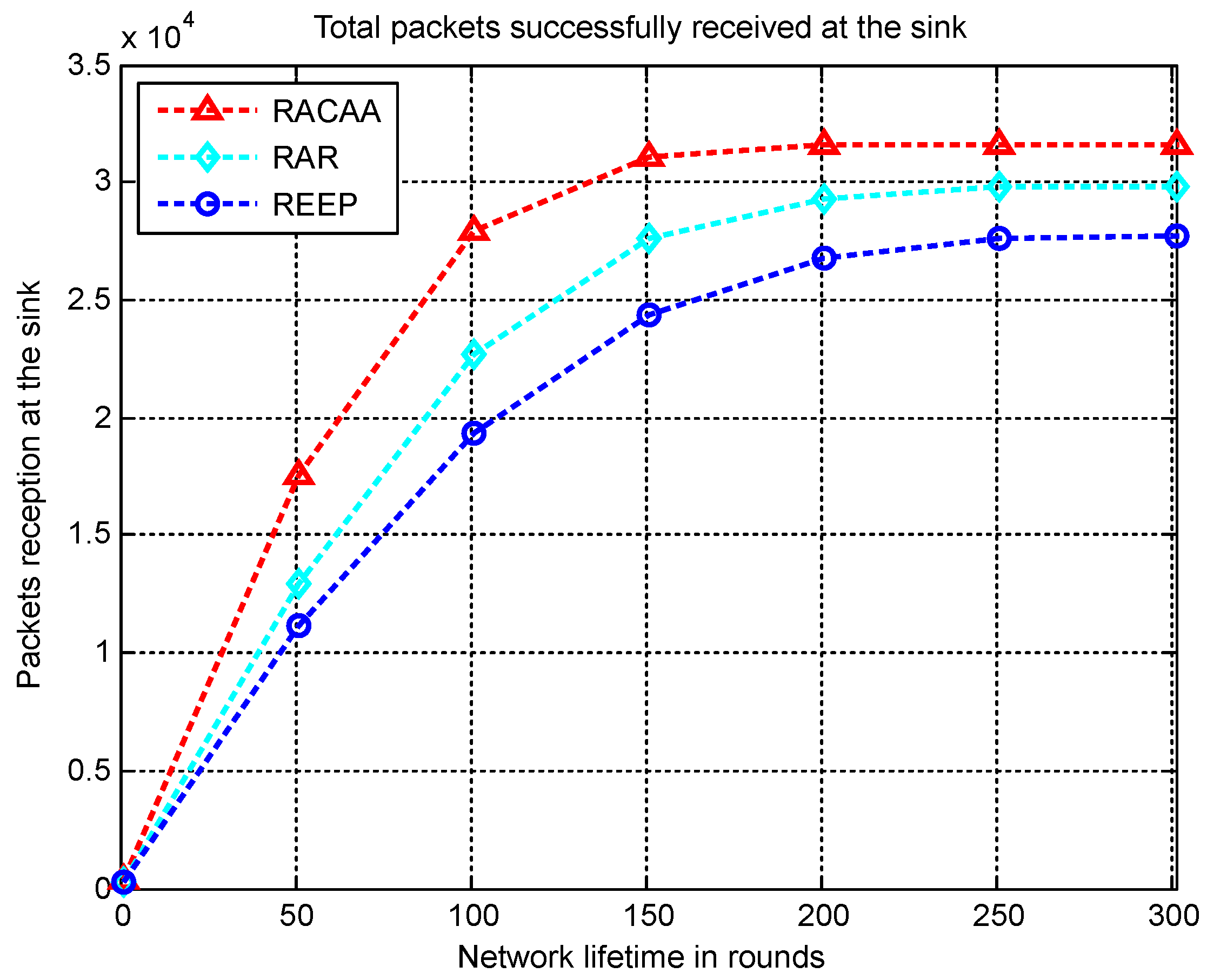
  • A reliability-aware routing (RAR) protocol is proposed for UAWSNs that considers the connectivity of the complete paths towards water surface rather than finding the conventional one- or two-hops neighbors. In addition, the probability of successfully transmitting a packet is computed for every chosen path. A path that is connected with water surface with the highest probability of successfully transmitting a packet is chosen as the path for data routing. These strategies overcome packets loss and enhance the probability of transferring packets to end destination with low delay as backed by simulation results.
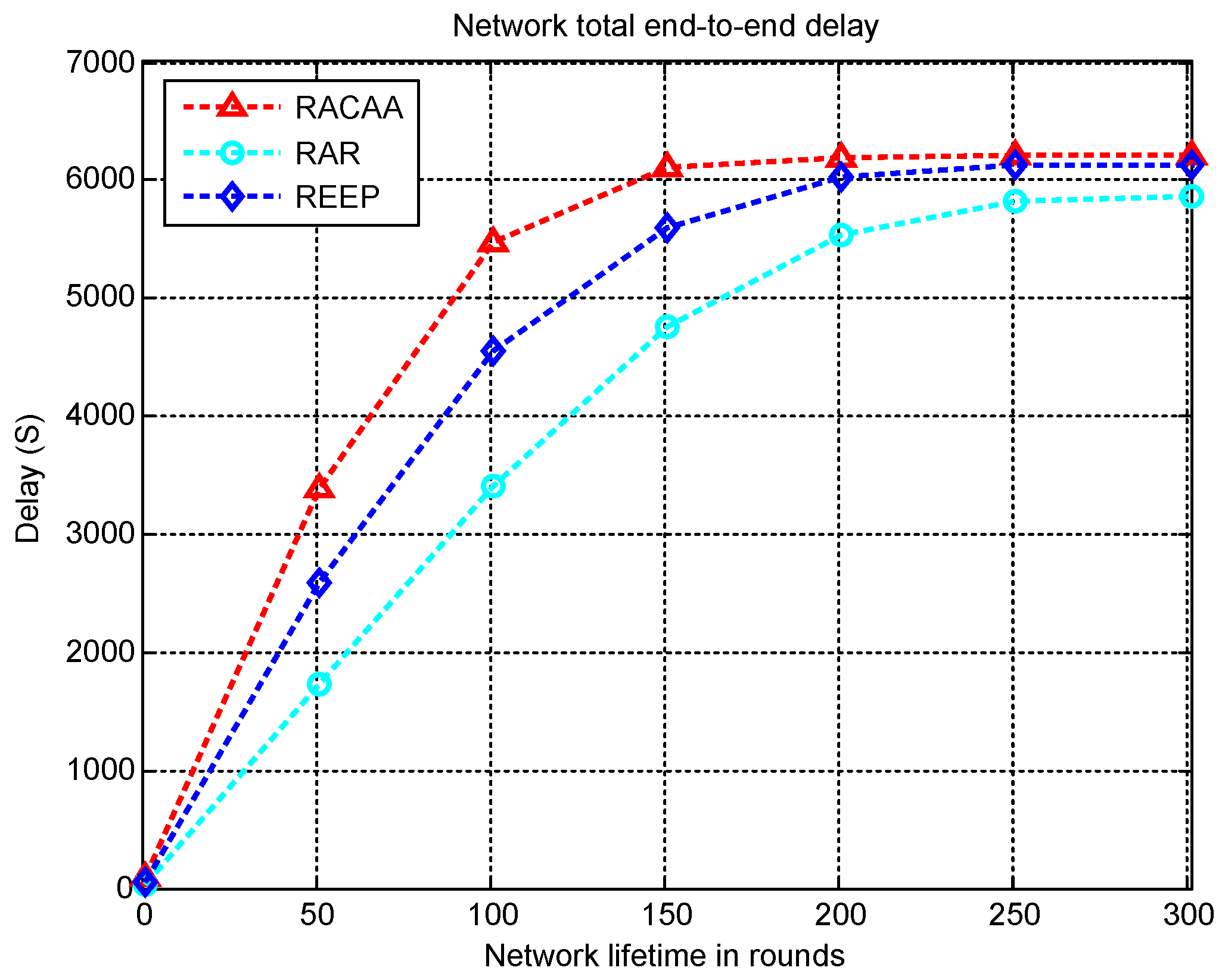
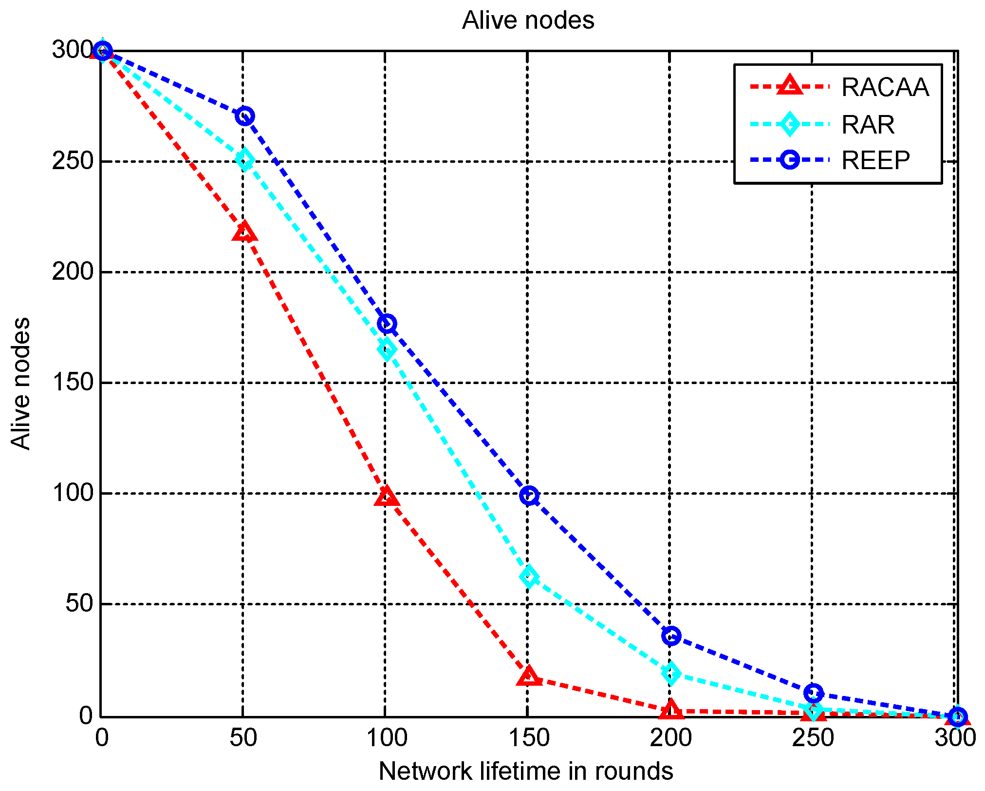
  • The underwater is a harsh medium with uncertainty. The condition of a routing link may change just before its computation and prior to information transmission, which may corrupt data packets. To counteract the effect of data corruption, cooperative routing with adaptive power control is combined with the RAR scheme that makes the RACAA scheme. In RACAA, a relay node is able to enhance its power level beyond the normal value if it finds that data packets have more than 50 % error. With increased power level, data packets are less prone to corruption by sea channel, as backed by simulation results. This strategy is different from the existing cooperative routing schemes where relay advances packets with fixed power and irrespective of channel conditions.
  • Both RAR and RACAA schemes make use of physical distance calculation using hello packets. This eliminates the need for knowing geographical positions of nodes within the sea as required in the conventional approach, which is challenging and cumbersome as nodes move with ocean tides.
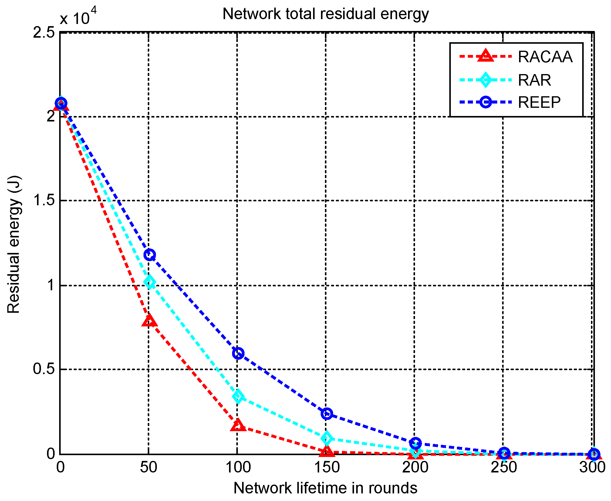
  • Based on performance evaluation, the RAR protocol can be used for applications involving reliability with time efficiency. That is, the RAR protocol is capable of high packets delivery in a short span of time. This makes it a first choice of underwater applications that require high throughput with minimal latency. Such applications include, for instance, naval warfare, under sea disaster prediction and prevention. On the other hand, the RACAA protocol can be used in applications involving reliability with delay tolerance, which means applications requiring high data throughput without taking into account the high delay associated with RACAA. Such applications include, for instance, sea bed exploration for mine reservoirs, water quality and pollution monitoring.

2. Related Work

This section describes routing protocols for UAWSNs that ensure reliability in packets delivery. The protocol in [5] considers reliable paths towards water surface in addition to interference by computing a cost function for every node. Computation of the cost function involves the physical distance between source and potential forwarder node, hop count of the potential forwarder from the sink and neighbor count of the forwarder node. The chosen forwarder node is the one with the smallest neighbor count and hops from water surface. The protocol achieves reliability in packets delivery to the sink node. However, it requires constant transmission of hello packets from the sink node that increases delay and energy consumption. In addition, the computation of the cost function involves too many parameters which compromises its computational efficiency.
The protocol proposed in [11] ensures reliable delivery of data packets by following two strategies. The first strategy ensures that every sensor node has a unique packet holding time so that sensor nodes do not forward packets simultaneously. This overcomes interference and, in effect, increases reliability in data transfer to the water surface. The second strategy allows a sensor node to increase its transmission range in the situation when no neighbor exists. The increase in transmission range is limited unless the sensor node finds one or more neighbor nodes. This overcomes packets drop and, in turn, enhances reliability in packets delivery. However, the protocol has high energy consumption when a sensor node increases its transmission range as more power is consumed in this case. In addition, a node may not find one or more neighbor nodes despite of the increased transmission range when few nodes are present in the network.
The grid-based adaptive routing protocol (GARP) [12] achieves reliable packets routing by dividing the entire network into grid cells. A node in one grid cell transmits packets to a node in another grid cell. When the connectivity of an existing path breaks, alternative paths are established for reliable packets transfer. However, the protocol performance is optimal only when the number of nodes in a grid cell is below a certain threshold. This limits the scalability and density of the network.
Connecting disjoint paths to establish routes for reliable data transfer is accomplished in [13]. Nodes communicate using request and reply messages to update each other about the desired information. This information is combined with the forward ratio to establish routes for data transfer. The designed protocol is also environment friendly and protects the marine animals during data forwarding. However, updating information about disconnected routes is cumbersome when nodes are far apart and when nodes move with ocean currents. To cope with the adverse channel conditions, the protocol proposed in [14] combines cooperative routing with opportunistic routing. Cooperative routing ensures reliability by receiving more than one a single copy of identical data packets at destination. Opportunistic routing avoids burden on specific low depth nodes. However, the protocol does not check the connectivity of the paths over which the packets are forwarded. Consequently, reliability is not guaranteed beyond one-hop neighbors of the source nodes.
The protocol proposed in [15] considers the underwater network as a cube and subdivides it into smaller cubes. Every cube has a cluster head selected based on the power it retains and its distance from the surface. Within every cube, selection of a relay node is accomplished on the bases of the existing power content of the battery, delay and distance from the water surface. The protocol ensures that the sink reliably receives packets. However, network is collapsed when the cluster head is dead. The authors in [16] argue that network coding and depth-based routing together improve the energy consumption, delay and reliability in packets transmission. However, sensor nodes are uniformly deployed and this state is difficult to maintain as nodes move with ocean tides.
The proposed RAR and RACAA schemes are different and unique from the existing schemes in that they both consider the connectivity of the complete path to water surface in routing packets. In addition, they both calculate the probability of successfully advancing packets over a route under consideration for routing. These strategies collectively enhance the packets delivery to sea surface. Furthermore, RACAA also adds cooperative routing to packets delivery. In this type of routing, a destination gets multiple data copies: from an original data broadcasting node and an intermediate relay node. The destination then combines these packets to extract the meaningful data.

3. RAR: Reliability-Aware Routing

This section provides an in-depth analysis of the reliability-aware routing scheme.

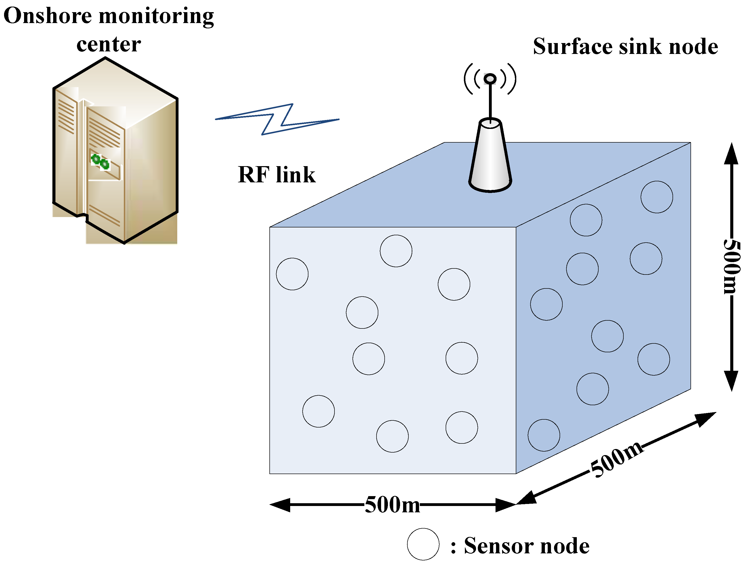
3.1. Network Structure and Nodes’ Deployment

The proposed network is a cube that starts from the surface of the water and ends at a depth of 500 m as shown in Figure 1. Within the network, senor nodes deployment is random, which is due to the reason that attributes that are to be sensed may occur at any part of the network and are not specific to any particular region of the network. Also, due to random deployment of nodes, the density of the nodes may vary in different parts of the network.
On account of greater attenuation of the radio waves in water, nodes involve acoustic signals to interact. Sink is hoisted at network’s uppermost cental surface as a master node that establishes communications with sensor nodes using acoustic waves. It gets data from nodes and advances it to the onshore data center. The onshore center gets packets from sink node by radio waves as it is the terrestrial environment where radio waves are generally used for fast communications. Unlike the usual approach that deploys two sensor nodes at network bottom to detect an attribute of interest [17], the proposed scheme assumes that detection of an attribute can be accomplished by every node. It provides greater coverage area in terms of detecting an attribute or event of interest. Since every node has a limited communication range, packets routing to sink by a node is achieved using multi-hopping, in case sink is beyond the node’s range of communication.

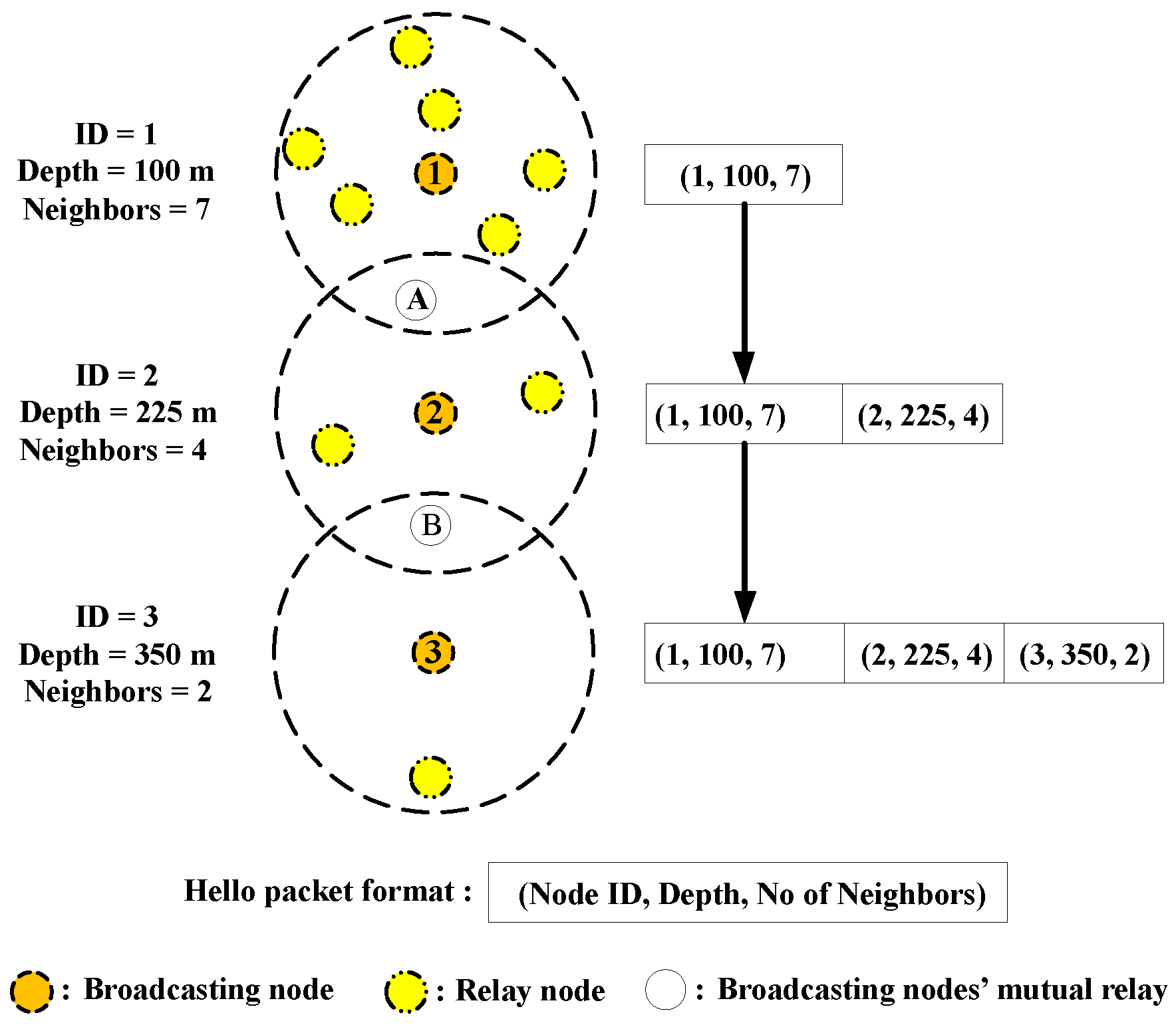
3.2. Determination of Neighbors and Their Information

Nodes’ deployment follows broadcasting of a hello packet by every sensor node. Initially, a hello packet comprises of the unique ID of the broadcasting node and its depth value. The depth value is known to every node using pressure sensor. After broadcasting the hello packet, every node waits for a preset particular interval of time to hear in response from its neighbors. This waiting interval is double of the time in which the hello packet reaches the farthest neighbor node from the broadcasting node plus the processing delay of the broadcasting node and its receiving neighbor. The double of the time from the broadcasting node to its farthest neighbor signifies the time of the two-way journey from the broadcasting node to the farthest neighbor and the corresponding reply the broadcasting node receives. Since all nodes have almost the same design parameters at the manufacturing level, the processing delay is assumed to be the same for all nodes. When a reply is not received within the predefined threshold time, the hello packet is broadcasted by the node again. It declares no neighbor when it does not receive any response even after it broadcasts the hello packet for the maximum number of times.
When a neighbor of the broadcasting node receives the hello packet, the node’s ID and depth values are inserted in the hello packet by the node, which is then broadcasted. The original broadcasting node receives this information. This process is repeated by every neighbor node. In this way, every node receives the vital information about its neighbors and knows its number of neighbors.
After knowing the number of its neighbors, a hello packet is broadcasted again by every node. This time the hello packet consists of the unique ID, depth and the neighbor count of the node that broadcasts it. When this packet is received by a neighbor node of the broadcasting node, it rebroadcasts the hello packet after inserting its own ID, depth and neighbor count. This process is repeated by every node. This leads to sharing of IDs, depth and neighbors information even among the sensor nodes that are not one-hop neighbors. Instead, such information is shared even among the multi-hop neighbors. This process is elaborated in Figure 2.
In Figure 2, a hello packet is broadcasted by node 1 comprising of its ID, depth and number of neighbor count denoted by ( 1 , 100 , 7 ) , respectively. This hello packet is different from the hello packet initially broadcasted by the sensor nodes just after deployment that contained broadcasting node’s ID and its depth. The hello packet broadcasted by node 1 is received by node 2 through the node A that acts as a relay node between node 1 and node 2. Node 2 adds its own information to the hello packet it receives from node 1 and broadcasts the extended hello packet. The extended hello packet now contains information about node 1 and node 2 as denoted by ( 1 , 100 , 7 ) and ( 2 , 225 , 4 ) , respectively. Finally, node 3 receives the extended hello packet through the relay node B, inserts its own information and broadcasts it in the form ( 1 , 100 , 7 ) ( 2 , 225 , 4 ) ( 3 , 350 , 2 ) . In this way, node 3 gets the vital information about its two-hops neighbor (node 1), in addition to its one-hop neighbor (node 2). In a similar fashion, node 1 also gets vital information about node 3, which is not shown in Figure 2 for simplicity. Every node performs this process and, in effect, every node gets information about the depth, IDs and neighbor count of its one- and multi-hop neighbors. This information is very critical in building reliable trajectories towards the water surface, as explained later.
To overcome redundant data transfer within a hello packet, every node uses a history buffer. As soon as a node gets a hello packet from a neighbor, it extracts the information about the ID, depth and neighbor count of the neighbor and saves it in a history buffer. Every node checks its history buffer so that only information about the nodes not in its history buffer are extracted and saved. This strategy reduces saving of redundant information as the history buffer has a limited capacity, although it can save important data of the total nodes in the network. This helps in identification of the reliable routing paths during data forwarding phase. Because sensor nodes move with ocean currents and die too due to battery depletion, they exchange hello packets after regular intervals of time to save energy and remain updated about the vital information of one another. It is because not updating the vital information of the sensor nodes leads to wrong routes selection during data forwarding.

3.3. Calculation of Physical Distance

After the sensor nodes exchange the vital information within a predefined interval of time, a control packet is sent by sink comprising of its own ID and the time of transmission. A node that receives this packet computes the distance by which it is apart from the sink using the time of reception of the packet [18]. The computed distance is then incorporated within the packet along with the ID and time of transmission by the broadcaster node. This process is repeated in the same manner as in Figure 2. However, this process is different from Figure 2 in that the packet is generated by the sink node at the top of the water surface. In this way, all nodes come to know physical distance of one another from the sink node as well as their mutual physical distance from one another. Such information later helps in building the reliable paths during data routing. The suppression of redundant packets in this case follows the same strategy as in Figure 2. The hello packet sent by the sink node is expired after the preset interval of time. This interval of time is set in such a way that even the farthest node in the network receives the hello packet.

3.4. Data Routing

When data is ready for transmission, a sensor node sends it directly to the sink node if the latter locates within its communication range. Otherwise, the node chooses multi-hopping. For multi-hopping, the sensor nodes select relay nodes in their neighborhood. Relay nodes posses the minimum depth. Selecting a relay node is accomplished by every node that has to advance data to another node. In multi-hopping, every senor node, that has to transmit data, computes all the paths from itself to the water surface through relay nodes. A path in which a relay node is absent from the sensor node to the water surface is discarded. It is because such a path does not provide connectivity to the water surface. This lack of connectivity results in loss of data packets along such a path, if selected. The information about the connectivity of a path and the availability of the relay nodes is already obtained during the exchange of hello packets.
After a sensor node selects all the connected paths from itself towards the water surface, the probability of error is estimated for every link that involves calculation of the average signal-to-noise ratio (SNR). Two nodes that are separated by a distance d and communicate using an acoustic signal of frequency f have an average SNR γ ¯ ( d , f ) as [19]
γ ¯ ( d , f ) = E b / A ( d , f ) N ( f ) × B
where E b , A ( d , f ) , N and B represent the average energy required in transmitting a single bit, attenuation, noise power density and the acoustic bandwidth, respectively. Fading in underwater environment can be modeled by the small scale Rayleigh fading [19]. Since, the channel fading inherently exhibits the exponential probability density function, the corresponding average SNR also exhibits the exponential probability density function, which for a specific value Γ of the SNR, is defined by [19]
f γ ¯ ( Γ ) = 1 γ ¯ e Γ γ ¯
for which the error probability, p e , is the integral of the product of the error probability at a particular value of the SNR, p e ( Γ ) , times the corresponding density function at that SNR [19], i.e.,
p e = 0 p e ( Γ ) f γ ¯ ( Γ ) d Γ .
The proposed schemes use BPSK modulation as in [19] for which the error probability is
p e = 1 2 1 ( γ ¯ 1 + γ ¯ )
and the corresponding probability of successfully delivering a single packet between nodes separated by a distance d is [19]
p s = ( 1 p e ) k
where k is the size of a single packet. For data routing, a sensor node selects the link that is connected from itself towards the water surface and has the highest probability of successfully delivering data packets.

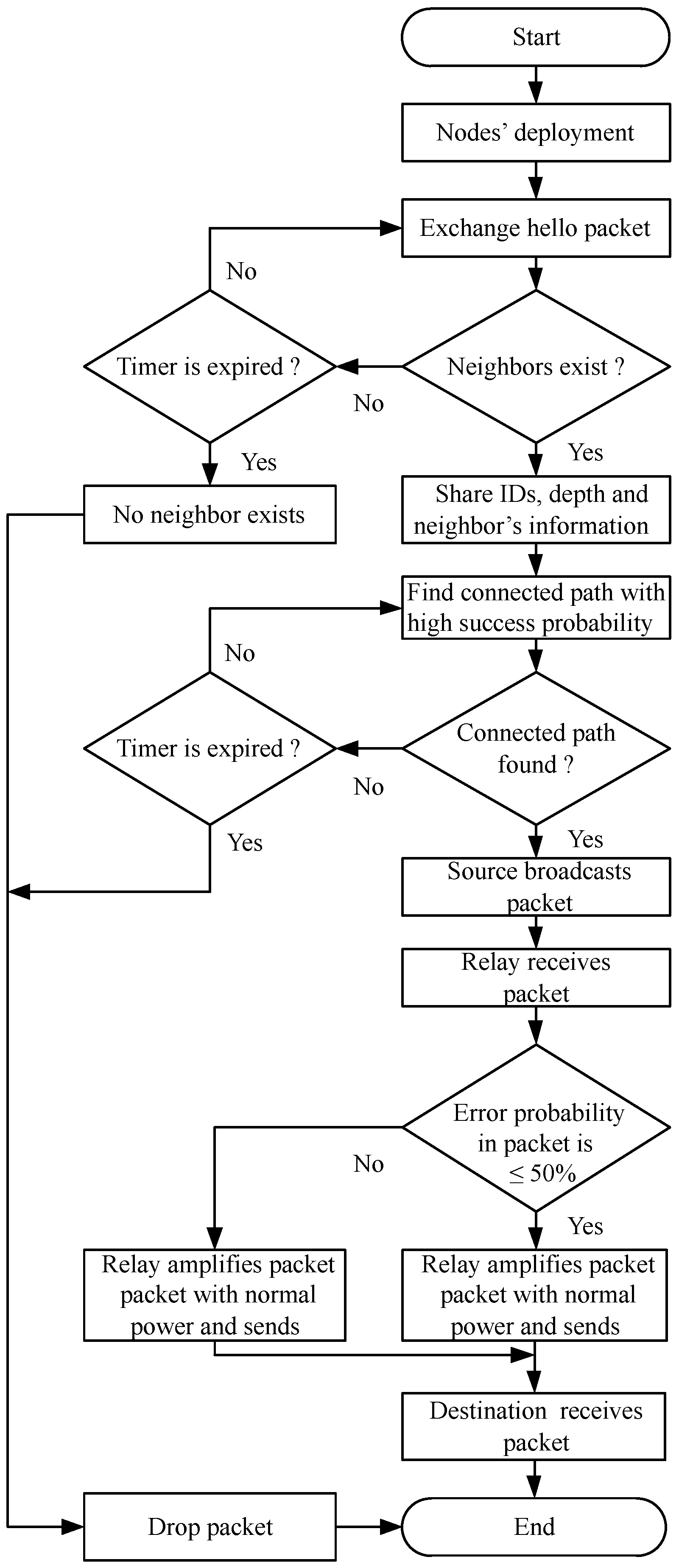
4. RACAA: Reliability-Aware Cooperative Routing with Adaptive Amplification

The RAR scheme advances data over a single link. Such a link may not be reliable always as the sea channel is harsh and unpredictable and its status may change after its computation and prior to information transmission. Therefore, to evaluate whether or not information is advanced over a reliable link, cooperative routing with adaptive power of relay nodes is added to RAR that makes the RACAA scheme. The description of the RACAA scheme is the same as the RAR scheme, except that the former uses cooperative routing with adaptive amplification of the received signal by the relay nodes. In adaptive amplification, a relay node increases its transmit power in forwarding information to destination when the error probability is above a certain threshold. The next section provides a detailed description of RACAA.

Cooperative Routing with Adaptive Amplification

In cooperative routing, data packets are broadcasted by a source node S and are received by a relay node R and a destination node D. At least a single relay node R between S and D also receives the broadcasted information. Such information is then transferred from R to D that combines the two copies of information to extract the desired information [20].
A data symbol x broadcasted by S is received by D as [20]
y S D = h S D x + n S D
where y S D is the signal received at D, h S D is the gain of the channel from S to D and n S D represents the additive white Gaussian noise (AWGN) along the S D link. The source broadcasted data symbol x, when received by R, is given as [20]
y S R = h S R x + n S R
where y S R is the signal received at R, h S R is the gain of the channel from S to R and n S R is the AWGN along the S R link. Adaptive amplification implies that at R, the received signal is amplified before transferring it to D when the error probability is above 50 % (a certain threshold) and is given by [20]
y R D = A 2 h R D y S R + n R D
where y R D is the signal that D receives from R, h R D is the gain of the channel along the along the R D link and n R D is the AWGN along the R to D link. The symbol A 2 denotes the factor by which the y S R signal is amplified by R and is mathematically defined by [20]
A 2 = ρ P s h S R 2 + σ 2
where the constant ρ equals either unity or the transmit power P R of the relay R. The proposed scheme takes ρ = P R and adjusts P R according to the bit error probability computed above. If the bit error probability of the packets at R is above 50%, this indicates unfavorable channel conditions. Therefore, the relay increases its transmit power to the maximum, otherwise it forwards packets to D with normal power. The increase in power of the relay helps in mitigating the the channel effects by increasing the SNR and, therefor, decreasing the bit error probability.
For the accomplishment of cooperative routing, at least three nodes are necessary to exist. They are: source, relay and destination nodes. Packets are generated and broadcasted by the source, which are received by the relay and destination. In RAR scheme, the destination node was not involved. Instead, data packets were broadcasted by a source and received by a relay, which further forwarded it towards end destination. The choice of relay node was made by source, which used to choose a lowest depth neighbor node as a relay. However, with cooperative routing in RACAA, source chooses a lowest depth neighbor as an intermediate destination. The relay node in RACAA is the one that has the lowest depth after the destination node and be a mutual neighbor of the source-destination pair.
In RACAA, the source broadcasted data packets are received by the destination and relay nodes. The relay node then waits for the destination node to receive a request whether or not to forward the same data packets to destination. The destination checks the error probability in data packets. If this probability is below the threshold, the destination does not request the relay node. The relay node knows this by not receiving a request from the destination node within the predefined interval of time that leads to timer expiration of the relay node. The timer of the relay node (for receiving a request from the destination node) starts as soon as the relay node receives the data packets from the destination node. Relay and destination nodes are selected by the source node using the vital information of nodes obtained by the exchange of hello packets.
Figure 3 is the flow chart of RAR and RACAA schemes that indicates the way packets are transferred to the water surface. It shows that deployment of nodes is followed by hello packets exchange to share the vital information with one anther. The vital information includes the number of neighbors, depth, ID and the physical distance by which a node is far from the surface sink. A source node at the verge of transmitting data first checks the existence of its neighbor nodes. If it does not find any neighbor, it checks again until the specified time for neighbors checking expires and, consequently, information is dropped. However, if neighbors are found, the source node checks that it has a connected path towards water surface. This is computed by looking at the number of neighbor nodes of all the nodes (from the neighborhood of the source node to sea surface) using the vital information of the sensor nodes obtained using hello packets exchange. If a connected path is found, the the source node advances packets. This process carries on unless the packets reach water surface or the timer is expired, which leads to dropping of packets.
As shown in Figure 3, the RACAA scheme adds one more step to the routing process of RAR. As soon as information packets are received by destination, it checks whether the error probability in data is below a certain threshold. If it is so, destination further advances the data. Otherwise, it sends a request to the relay node to send the data to it. The source then combines all the copies of data, from source and relay, and extracts the desired information. This process continues unless information packets reach to surface sink.

5. Performance Evaluation

MATLAB is used as a simulation tool and the collected data is averaged over 50 cycles, as the fluctuations in performance of all the schemes stopped at 50 cycles. Table 1 shows the parameters taken into account during simulations.
The proposed protocols are compared with REEP protocol proposed in [4]. It is because reliability in packets advancement is also addressed by REEP. For the sake of fair comparison, the mobility model of nodes and the medium access control (MAC) protocols considered in REEP are also considered in the proposed schemes. It is because to evaluate the performance of the schemes based on their defined parameters only. The performance metrics are plotted against the rounds. A single round corresponds to the time from the transmission of data packets by a single or multiple nodes unless they are either received at water surface by the sink or dropped along the way.
Figure 4 depicts the packets count reaching successfully to water surface. The RACAA advances the maximum number of packets to water surface. It is due to three reasons. Firstly, cooperative routing transfers packets in RACAA over more than one route i.e., along source-destination and relay-destination routes. Therefore, if packets are lost along one route, there is a probability that they may not have lost along the other path. Secondly, due to adaptive amplification, a relay node in RACAA increases its transmit power to the maximum level when error probability in packets is above 50 % . This combats the unfavorable channel conditions. Thirdly, RACAA chooses connected paths towards water surface with the highest probability of successfully transferring packets, which further aids in successful packets delivery to water surface. Although RAR also chooses connected paths towards water surface with the highest probability of successfully transferring packets, it lacks cooperative routing with adaptive amplification of relay nodes as in RACAA. REEP does not take into consideration connected paths towards water surface beyond one-hop nor it takes into account the probability of successfully transmitting a packet over a route. As a result, RACAA achieves the highest delivery of packets to the sink.
The RAR has more packets advanced to the sink than REEP. The reason is that RAR considers connected paths towards water surface and computes probability of successfully advancing packets over selected routes. On the other hand, REEP chooses paths with forwarder nodes available for one-hop neighbors only and it lacks the computation of probability of successful delivery of packets over a selected route. As a result, RAR has more packets reached to the sink than REEP.
The residual energy behavior is presented in Figure 5, which depletes in the most rapid manner in RACAA. This is due to the cost paid for reliable delivery of packets in the form of computation of connected paths towards water surface, transmit power enhancement by nodes during unfavorable conditions and cooperative routing. All these factors lead to nodes’ highest energy consumption in RACAA and, therefor, the lowest residual energy is left with the nodes. Nodes in RAR consume energy in the same fashion as in RACAA except that the former does not involve cooperative routing. The absence of cooperation routing reduces energy consumption in RAR. Therefore, RAR has lower energy consumption than RACAA. As a result, nodes have more residual energy in RAR than RACAA. RAR considers connected paths towards sea surface and computes packets delivery probability over a selected route. This leads to more advancement of packets towards sea surface than REEP. Consequently, RAR’s energy consumption becomes higher than REEP that, in turn, leaves less residual energy with RAR.
The pattern with which nodes remain alive in the network is exhibited in Figure 6. The least residual energy left with the nodes in RACAA makes the least number of nodes alive. In other words, RACAA has the most dead nodes due to the least residual energy left with the nodes as the network operation proceeds. Likewise, the lower residual energy left with the nodes in RAR than REEP leaves fewer alive nodes with the former than the latter. Alternatively, RAR has more dead nodes than REEP as the network operates.
Figure 7 shows the latency pattern. The highest latency of RACAA is due to cooperative routing in which reception of source broadcasted information is accomplished by relay and destination. The relay node further sends the information to the destination. This almost doubles the transmission path over which packets are transmitted. The destination further combines these packets and consumes extra processing time. Cooperative routing is absent in RAR and REEP. As a result, latency becomes the highest in RACAA. RAR has a shorter latency than REEP due to the difference in the transmission manner of hello packets. Before information transmission, every time a node in REEP sends a hello packet to the neighbors for acquiring the information necessary for forwarder selection. This introduces extra latency and computation. On the other hand, obtaining neighbors’ information is accomplished only in regular intervals of time in RAR. As a result, RAR has a shorter latency than REEP.

6. Conclusions and Future Work

Two routing protocols: reliability-aware routing (RAR) and reliability-aware cooperative routing with adaptive amplification (RACAA) are proposed for underwater acoustic wireless sensor networks (UAWSNs). RAR considers routing paths towards water surface with available relay nodes. Among all the selected paths, the most reliable path is chosen for packets forwarding. A reliable path has connected sensor nodes towards water surface and the highest probability of successfully transferring the data packets to surface sink. RACAA adds cooperative routing to RAR with adaptive amplification in which a relay node can increase its transmit power to cope with the fluctuating channel effects on data. Simulation results exhibit that RAR has superior performance in packets delivery to sea surface with lower delay. Similarly, RACAA further improves the packets delivery as RAR considers a single link for data routing which may not be always reliable. Since connected paths to water surface are chosen, nodes close to water surface bear more data traffic. To address this issue, a specific time frame for data processing will be defined in future investigation. The sensors nodes will process data only when they are requested by other nodes or when they sense some attribute and generate data packets by themselves. Otherwise, the sensor nodes will remain in dormant mode to conserve energy.

Author Contributions

A.K. proposed and implemented the main idea. S.M.A., I.A. and A.U.R. responded to the comments of the reviewers and streamlined the presentation of the manuscript.

Funding

This research work is supported in part by the University of Malaya under Postgraduate Research Grant (PG035-2016A).

Conflicts of Interest

The authors declare no conflict of interest.

References

  1. Khasawneh, A.; Latiff, M.S.; Kaiwartya, O.; Chizari, H. A reliable energy-efficient pressure-based routing protocol for underwater wireless sensor network. Wirel. Netw. 2018, 24, 2061–2075. [Google Scholar] [CrossRef]
  2. Heidemann, J.; Stojanovic, M.; Zorzi, M. Underwater sensor networks: Applications, advances and challenges. Philos. Trans. R. Soc. 2011, 370, 158–175. [Google Scholar] [CrossRef]
  3. Khan, A.; Ali, I.; Ghani, A.; Khan, N.; Alsaqer, M.; Rahman, A.; Mahmood, H. Routing protocols for underwater wireless sensor networks: Taxonomy, research challenges, routing strategies and future directions. Sensors 2018, 18, 1619. [Google Scholar] [CrossRef] [PubMed]
  4. Rahman, Z.; Hashim, F.; Othman, M.; Rasid, M.F. Reliable and energy efficient routing protocol (REEP) for underwater wireless sensor networks (UWSNs). In Proceedings of the IEEE 12th Malaysia International Conference on Communications, Kuching, Malaysia, 23–25 November 2015. [Google Scholar]
  5. Majid, A.; Azam, I.; Khan, T.; Sangeen; Khan, Z.A.; Qasim, U.; Javaid, N. A reliable and interference-aware routing protocol for underwater wireless sensor networks. In Proceedings of the IEEE 10th International Conference on Complex, Intelligent and Software Intensive Systems, Fukuoka, Japan, 6–8 July 2016. [Google Scholar]
  6. Shah, S.; Khan, A.; Ali, I.; Ko, K.M.; Mahmood, H. Loclization free energy efficient and cooperative routing protocols for underwater wireless sensor networks. Symmetry 2018, 10, 498. [Google Scholar] [CrossRef]
  7. Ullah, U.; Khan, A.; Altowaijri, S.M.; Ali, I.; Rahman, A.U.; Kumar, V.; Ali, M.; Mahmood, H. Cooperative and delay minimization routing schemes for dense underwater wireless sensor networks. Symmetry 2019, 11, 195. [Google Scholar] [CrossRef]
  8. Yang, G.; Dai, L.; Wei, Z. Challenges, threats, security issues and new trends of underwater wireless sensor networks. Sensors 2018, 18, 3907. [Google Scholar] [CrossRef]
  9. Li, N.; Martinez, J.F.; Chaus, J.M.M.; Eckert, M. A survey on underwater acoustic sensor networkr routing protocols. Sensors 2016, 16, 414. [Google Scholar] [CrossRef]
  10. Hao, K.; Jin, Z.; Shen, H.; Wang, Y. An efficient and reliable geographic routing protocol based on partial network coding for underwater sensor networks. Sensors 2015, 15, 12720–12735. [Google Scholar] [CrossRef] [PubMed]
  11. Khan, A.; Ahmedy, I.; Anisi, M.; Javaid, N.; Ali, I.; Khan, N.; Alsaqer, M.; Mahmood, H. A localization-free interference and energy holes minimization routing for underwater wireless sensor networks. Sensors 2018, 18, 165. [Google Scholar] [CrossRef]
  12. Day, K.; Touzene, A.; Arafeh, B.; Alzeidi, N. GARP: A Highly reliable grid-based adaptive routing protocol for underwater wireless sensor networks. Int. J. Comput. Commun. Netw. 2017, 9, 71–82. [Google Scholar] [CrossRef]
  13. Li, Y.; Jin, Z.; Su, Y.; Yang, M.; Xiao, S. An environment-friendly multipath routing protocol for underwater acoustic sensor network. J. Sens. 2017, 2017, 1–8. [Google Scholar] [CrossRef]
  14. Rehman, M.A.; Lee, Y.; Koo, I. EECOR: An energy-efficient cooperative opportunistic routing protocol for underwater acoustic sensor networks. IEEE Access 2017, 5, 14119–14132. [Google Scholar] [CrossRef]
  15. Wang, K.; Gao, H.; Xu, X.; Jiang, J.; Yue, D. An energy-efficient reliable data trasmission scheme for complex environmental monitoring in uderwater acoustic sensor networks. IEEE Sens. J. 2016, 16, 4051–4062. [Google Scholar] [CrossRef]
  16. Diao, B.; Xu, Y.; Wang, Q.; Chen, Z.; Li, C.; An, Z.; Han, G. A reliable depth-based routing protocol with network coding for underwater sensor network. In Proceedings of the IEEE 22nd International Conference on Parallel and Distributed Systems, Wuhan, China, 13–16 December 2016. [Google Scholar]
  17. Morozs, N.; Mitchell, P.; Zakharov, Y.V. TDA-MAC: TDMA without clock synchronization in underwater acoustic networks. IEEE Access 2017, 6, 1091–1108. [Google Scholar] [CrossRef]
  18. Valente, J.F.; Alves, J.C. Real-time TDOA measurements of an underwater acoustic source. In Proceedings of the IEEE Technology Society Conference, Monterey, CA, USA, 19–23 September 2016. [Google Scholar]
  19. Noh, Y.; Lee, U.; Wang, P.; Vieira, L.F.M.; Gerla, J.-H.C.M.; Kim, K. Hydrocast: Pressure routing for underwater sensor networks. IEEE Trans. Veh. Technol. 2016, 65, 333–347. [Google Scholar] [CrossRef]
  20. Bello, O.; Zen, H.; Othman, A.K.; Hamid, K.A. Computing amplify-and-forward relay amplification factor to improve total capacity at destination. Am. J. Appl. Sci. 2015, 12, 572–580. [Google Scholar] [CrossRef]
Figure 1. Network model.
Symmetry 11 00421 g001
Figure 2. Strategy for sharing ID, depth and neighbors information among one-and-multi-hop neighbor sensor nodes.
Symmetry 11 00421 g002
Figure 3. Flow chart of RAR and RACAA.
Symmetry 11 00421 g003
Figure 4. Number of packets successfully reached to the water surface.
Symmetry 11 00421 g004
Figure 5. Total residual energy.
Symmetry 11 00421 g005
Figure 6. Active nodes.
Symmetry 11 00421 g006
Figure 7. Delay.
Figure 7. Delay.
Symmetry 11 00421 g007
Table 1. Simulation metrics.
MetricExtent
Node’s reception mode power consumption0.8 W
Node’s transmit mode power consumption2–4 W
Node’s idle mode power consumption10 mW
Size of a single packet50 B
Size of a hello packet5 B
Transmission range200 m
No of sensor nodes300
Acoustic speed1500 m/s
Network size 500 × 500 × 500
Data rate10 kbps

