The Use of Structural Symmetries of a U12 Engine in the Vibration Analysis of a Transmission


Abstract
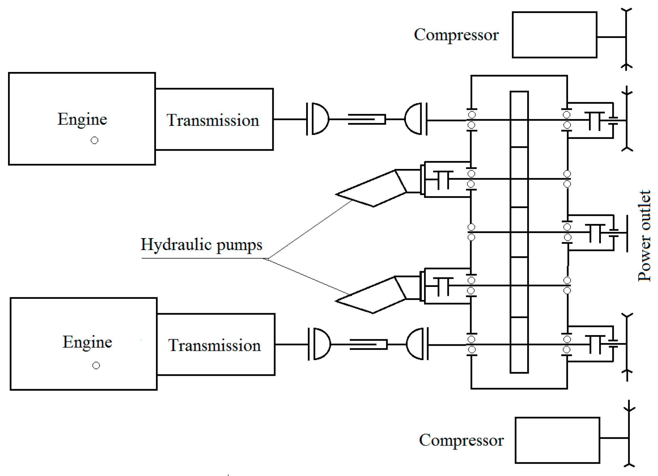
:1. Introduction
2. Materials and Methods
3. Results
3.1. Theorem T1. The Eigenvalues for the System (3) are Eigenvalues for the System (2) As Well
3.2. If We Consider the Square Polynomial Matrices with Complex Coefficients, of Size n, Noted A, B, C, L, Z = On and matrix , then det(M) is Dividable by det(A)
- For j1 = 1, jn = n we have .
- For j1 = 2n + 1, jn = 3n we have and .
- For the rest, we notice that:
- if there is an index then the column k from is null thus .
- is non-null if and in this case where . For such a fixed we have three possibilities for namely:
- has a column 0 thus = 0;
- = det(A);
- = . In this case, we can determine in a unique way the matrix for each of the two possible versions:
- If there is then contains twice the column Lt thus ;
- If then we consider and will be a determinant having the same C type columns located in the same position as in and the L type columns will be the same but permutated as far as the position is concerned. A direct calculation of signs will lead to .
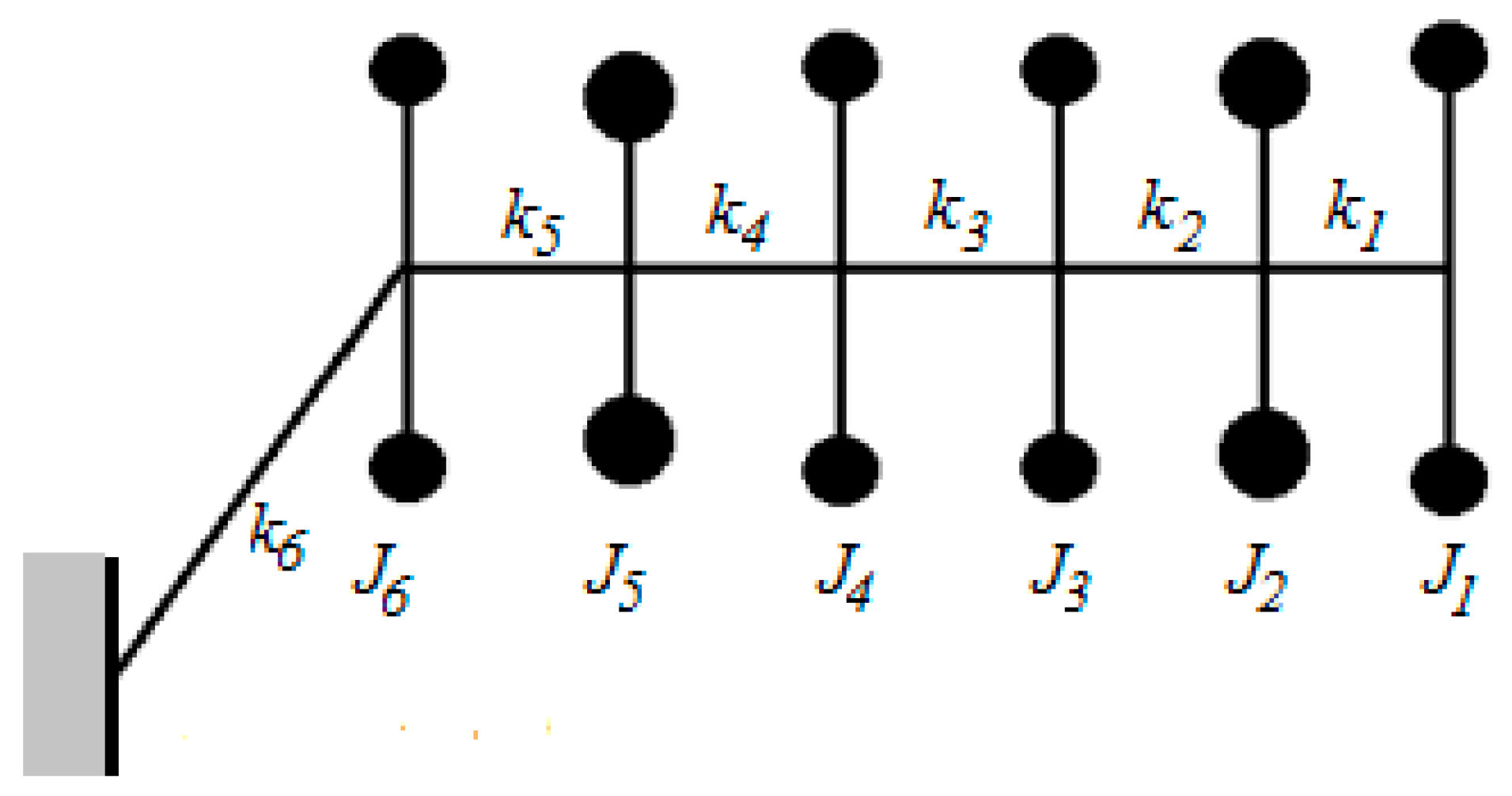
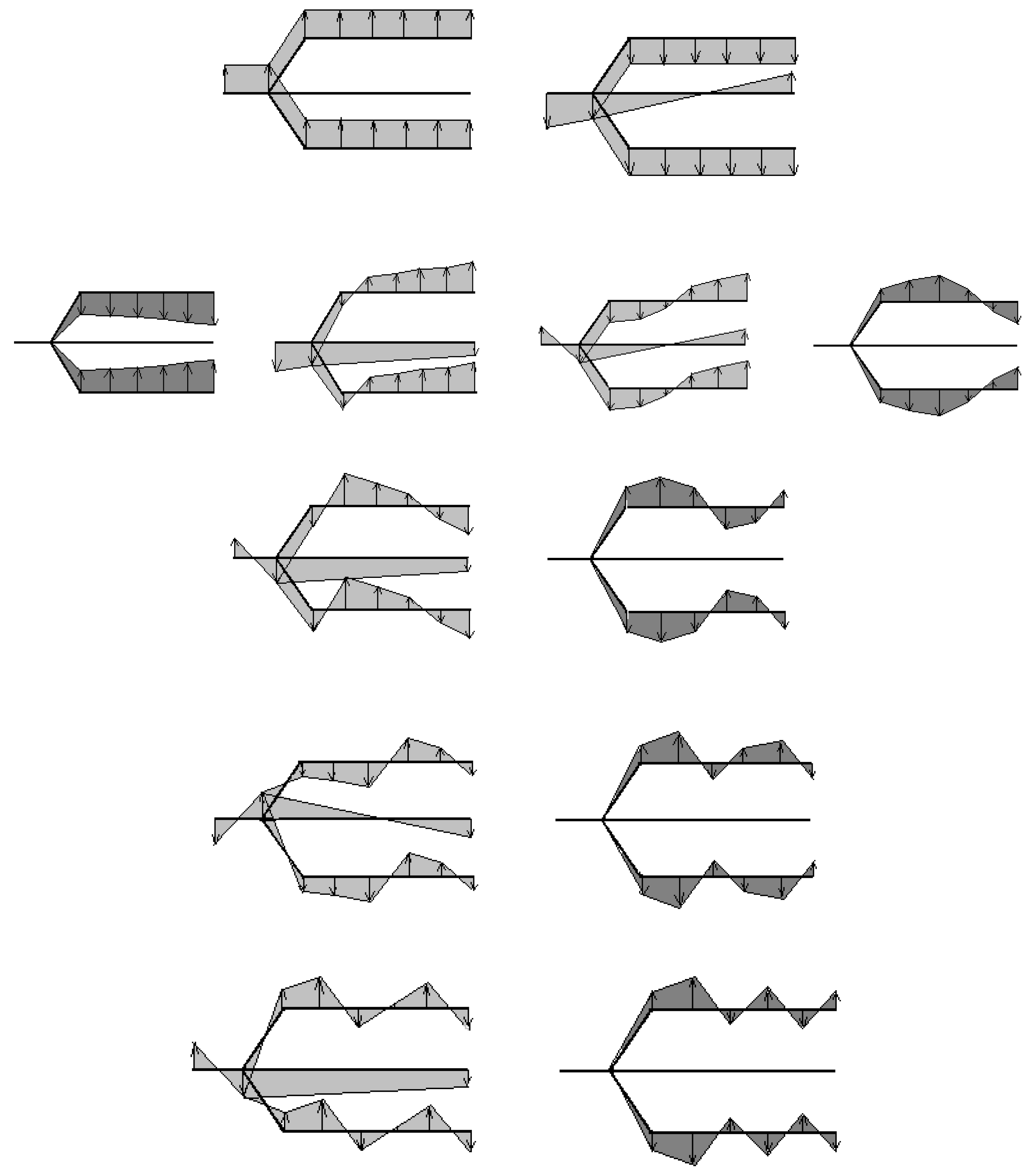
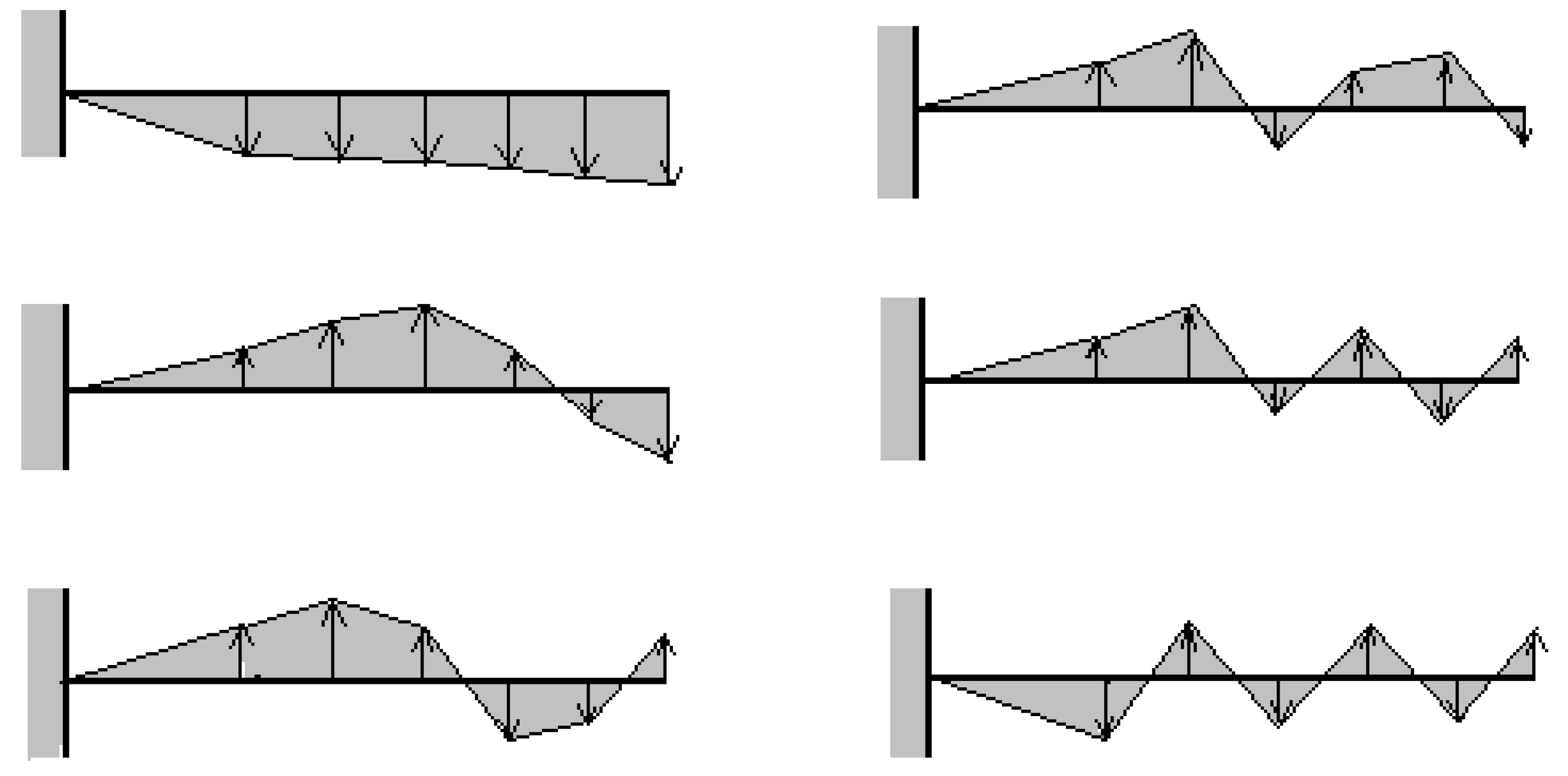
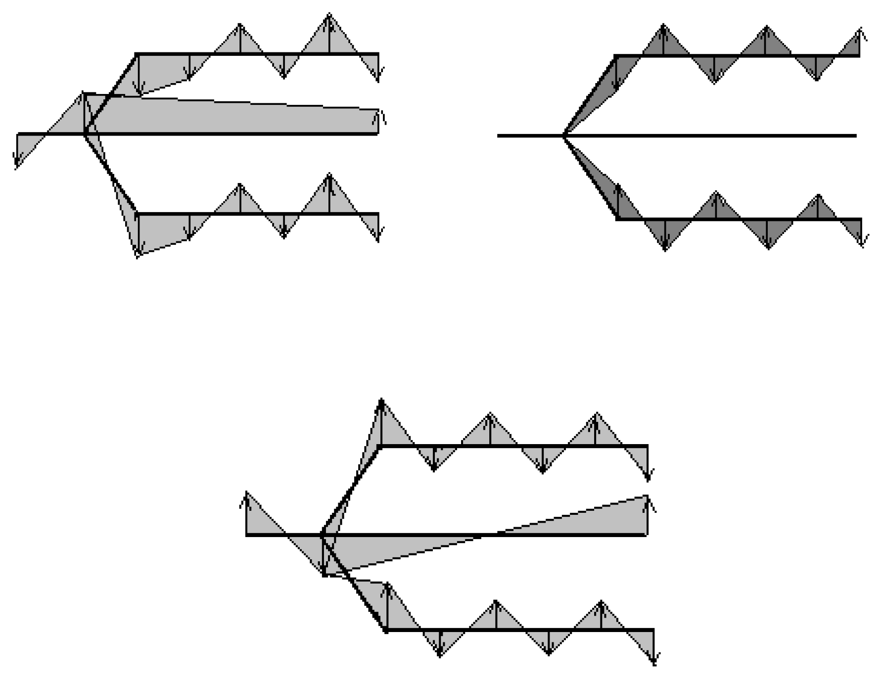
3.3. The Natural Modes of Vibration
4. Discussion
Author Contributions
Funding
Conflicts of Interest
References
- Ambrus, C. Analiza Dinamică a Solicitărilor din Ansamblul Motor-Transmisie al Instalațiilor Mobile de Foraj de Mare Putere (Dynamic Analysis of Stresses in the Motor-Transmission Assembly of Mobile Power Drilling Installations). Ph.D. Thesis, Transylvania University of Brasov, Brasov, Romania, 2017. [Google Scholar]
- Holm, D.D.; Stoica, C.; Ellis, D.C.P. Geometric Mechanics and Symmetry; Oxford University Press: Oxford, UK, 2009. [Google Scholar]
- Marsden, J.E.; Ratiu, T.S. Introduction to Mechanics and Symmetry: A Basic Exposition of Classical Mechanical Systems; Springer: Berlin/Heidelberg, Germany, 2003; ISBN 13 978-0387986432. [Google Scholar]
- Singer, S.F. Symmetry in Mechanics; Springer: Berlin/Heidelberg, Germany, 2004; ISBN 978-1-4612-0189-2. [Google Scholar]
- Celep, Z. On the axially symmetric vibration of thick circular plates. Ingenieur-Archiv 1978, 47, 411–420. [Google Scholar] [CrossRef]
- Chen, Y.; Feng, J. Generalized Eigenvalue Analysis of Symmetric Prestressed Structures Using Group Theory. J. Comput. Civ. Eng. 2012, 26, 488–497. [Google Scholar] [CrossRef]
- Zavadskas, E.K.; Bausys, R.; Antucheviciene, J. Civil Engineering and Symmetry. Symmetry 2019, 14, 501. [Google Scholar] [CrossRef]
- Mechanics and symmetry in Europe: The geometry and dynamics of deformable systems. Project. HPRN-CT-2000-00113, Funded under: FP5-HUMAN POTENTIAL, University of Surrey, United Kingdom, Centre National de la Reserche Scientifique, France, Instituto Superior Tecnico, Portugal, Swiss Federal Institute of Technology of Nottingham, Switzerland, Universita degli studi di Padova, Italy, University of Nottingham, United Kingdom, Universite du Litoral, France, Utrecht University, Netherlands. Available online: https://cordis.europa.eu/project/rcn/53964/factsheet/en (accessed on 12 October 2019).
- Ganghoffer, J.F.; Mladenov, I. Similarity, Symmetry and Group Theoretical Methods in Mechanics; International Centre for Mechanical Sciences: Udine, Italy, 2015. [Google Scholar]
- Mangeron, D.; Goia, I.; Vlase, S. Symmetrical Branched Systems Vibrations. Sci. Mem. Rom. Acad. 1991, 12, 232–236. [Google Scholar]
- Weimann, S.; Kremer, M.; Plotnik, Y.; Lumer, Y.; Nolte, S.; Makris, K.G.; Segev, M.; Rechtsman, M.C.; Szameit, A. Topologically protected bound states in photonic parity-time-symmetric crystals. Nat. Mater. 2017, 16, 433–438. [Google Scholar] [CrossRef] [PubMed]
- Wang, B.; Yang, H.L.; Meng, F.W. Sixth-order symplectic and symmetric explicit ERKN schemes for solving multi-frequency oscillatory nonlinear Hamiltonian equations. Calcolo 2017, 54, 117–140. [Google Scholar] [CrossRef]
- Niiranen, J.; Balobanov, V.; Kiendl, J.; Hosseini, S.B. Variational formulations, model comparisons and numerical methods for Euler-Bernoulli micro- and nano-beam models. Math. Mech. Solids 2019, 24, 312–335. [Google Scholar] [CrossRef]
- Bourada, F.; Amara, K.; Bousahla, A.A.; Tounsi, A.; Mahmoud, S.R. A novel refined plate theory for stability analysis of hybrid and symmetric S-FGM plates. Struct. Eng. Mech. 2018, 68, 661–675. [Google Scholar]
- Sun, X.J.; Zhang, H.; Meng, W.J.; Zhang, R.H.; Li, K.N.; Peng, T. Primary resonance analysis and vibration suppression for the harmonically excited nonlinear suspension system using a pair of symmetric viscoelastic buffers. Nonlinear Dyn. 2018, 94, 1243–1265. [Google Scholar] [CrossRef]
- Vlase, S.; Păun, M. Vibration analysis of a mechanical system consisting of two identical parts. Rom. J. Tech. Sci. Appl. Mech. 2015, 60, 216–230. [Google Scholar]
- Vlase, S.; Marin, M.; Scutaru, M.L.; Munteanu, R. Coupled transverse and torsional vibrations in a mechanical system with two identical beams. AIP Adv. 2017, 7, 065301. [Google Scholar] [CrossRef]
- Othman, M.I.A.; Marin, M. Effect of thermal loading due to laser pulse on thermoelastic porous medium under G-N theory. Results Phys. 2017, 7, 3863–3872. [Google Scholar] [CrossRef]
- Vlase, S.; Năstac, D.C.; Marin, M.; Mihălcică, M. A method for the study of the vibration of mechanical bars systems with symmetries. Acta Tech. Napoc. Ser. Appl. Math. Mech. Eng. 2017, 60, 539. [Google Scholar]
- Hassan, M.; Marin, M.; Ellahi, R.; Alamri, S.Z. Exploration of convective heat transfer and flow characteristics synthesis by Cu–Ag/water hybrid-nanofluids. Heat Transf. Res. 2018, 49, 1837–1848. [Google Scholar] [CrossRef]
- Zingoni, A. Symmetry recognition in group-theoretic computational schemes for complex structural systems. Comput. Struct. 2012, 94–95, 34–44. [Google Scholar] [CrossRef]
- Zingoni, A. Group-theoretic exploitations of symmetry in computational solid and structural mechanics. Int. J. Numer. Methods Eng. 2009, 79, 253–289. [Google Scholar] [CrossRef]
- Zingoni, A. Group-theoretic insights on the vibration of symmetric structures in engineering. Philos. Trans. R. Soc. A Math. Phys. Eng. Sci. 2014, 372. [Google Scholar] [CrossRef]
- Catalog. Roman Autocamioane S.A Brașov. Roman Trucks & Buses—Special vehicles. 2012. Available online: http://www.roman.ro/index.php?lang=ro&showlang=&cat=PRODUSE%20/%20AUTOVEHICULE%20CIVILE&subcat=Autovehicule%20pentru%20industria%20petroliera&subid=3112&main=produse&end=fnpr (accessed on 12 October 2019).
- Horn, R.A.; Johnson, C.R. Matrix Analysis; Cambridge University Press: Cambridge, UK, 1985. [Google Scholar]


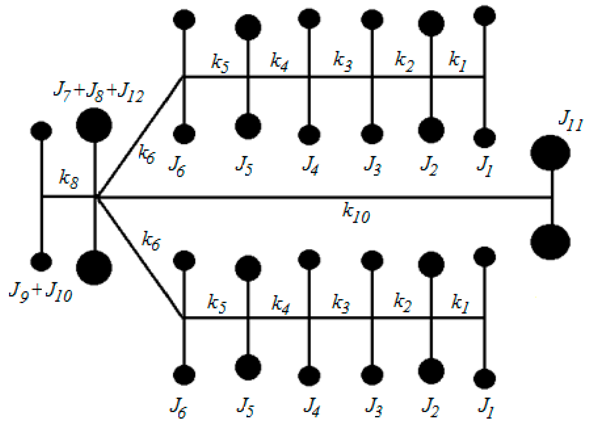
| No. | Moment of Inertia | Details |
|---|---|---|
| 1 | J1 | Cylinder 1 |
| 2 | J2 | Cylinder 2 |
| 3 | J3 | Cylinder 3 |
| 4 | J4 | Cylinder 4 |
| 5 | J5 | Cylinder 5 |
| 6 | J6 | Cylinder 6 |
| 7 | J7, J12 | Gears |
| 8 | J8 | Central Gear |
| 9 | J9 | Flywheel |
| 10 | J10 | Ventilator |
| 11 | J11 | Exit steering wheel |
| No. | Rear Clutch Model | Front Clutch Model | ||
|---|---|---|---|---|
| Moment of Inertia | Values (kg*m2) | Moment of Inertia | Values (kg*m2) | |
| 1 | J1 | 0.1048 | J1 | 0.1048 |
| 2 | J2 | 0.0638 | J2 | 0.0638 |
| 3 | J3 | 0.1048 | J3 | 0.1048 |
| 4 | J4 | 0.1048 | J4 | 0.1048 |
| 5 | J5 | 0.0638 | J5 | 0.0638 |
| 6 | J6 | 0.1048 | J6 | 0.1048 |
| 7 | J7+J8+J12 | 1.81182 | J7+J8+J12 | 1.4157 |
| 8 | J9 | 3.41895 | J9 | 2.9841 |
| 9 | J11 | 3.70752 | J11 | 1.3382 |
| Between | Rear Clutch Model | Front Clutch Model | ||
|---|---|---|---|---|
| Stiffness | Values (Nm/rad) | Stiffness | Values (Nm/rad) | |
| 1–2 | k1 | 2.56 × 10⁶ | k1 | 2.56 × 10⁶ |
| 2–3 | k2 | 2.56 × 10⁶ | k2 | 2.56 × 10⁶ |
| 3–4 | k3 | 2.53 × 10⁶ | k3 | 2.53 × 10⁶ |
| 4–5 | k4 | 2.56 × 10⁶ | k4 | 2.56 × 10⁶ |
| 5–6 | k5 | 2.56 × 10⁶ | k5 | 2.56 × 10⁶ |
| 6–7 | k6 | 20.87 × 10⁶ | k6 | 20.87 × 10⁶ |
| 7–8 | k7 | 12.67 × 10⁶ | k7 | 4.683 × 10⁶ |
| 7–9 | k8 | 0.045961 × 10⁶ | k8 | 0.030158 × 10⁶ |
| No | Rear Clutch Model | Front Clutch Model | Single Engine Model |
|---|---|---|---|
| Eigenvalues (rpm) | Eigenvalues (rpm) | Eigenvalues (rpm) | |
| 1 | 0 | 0 | |
| 2 | 1.338 | 1.596 | |
| 3 | 14.062 | 13.449 | |
| 4 | 14.564 | 14.062 | 14.062 |
| 5 | 30.417 | 22.397 | |
| 6 | 40.278 | 40.278 | 40.278 |
| 7 | 41.483 | 41.329 | |
| 8 | 67.067 | 67.067 | 67.067 |
| 9 | 67.561 | 67.632 | |
| 10 | 92.764 | 92.764 | 92.764 |
| 11 | 93.394 | 93.553 | |
| 12 | 100.959 | 100.959 | 100.959 |
| 13 | 101.039 | 101.056 | |
| 14 | 144.921 | 144.921 | 144.921 |
| 15 | 151.079 | 152.676 |
© 2019 by the authors. Licensee MDPI, Basel, Switzerland. This article is an open access article distributed under the terms and conditions of the Creative Commons Attribution (CC BY) license (http://creativecommons.org/licenses/by/4.0/).
Share and Cite
Mihălcică, M.; Vlase, S.; Păun, M. The Use of Structural Symmetries of a U12 Engine in the Vibration Analysis of a Transmission. Symmetry 2019, 11, 1296. https://doi.org/10.3390/sym11101296
Mihălcică M, Vlase S, Păun M. The Use of Structural Symmetries of a U12 Engine in the Vibration Analysis of a Transmission. Symmetry. 2019; 11(10):1296. https://doi.org/10.3390/sym11101296
Chicago/Turabian StyleMihălcică, Mircea, Sorin Vlase, and Marius Păun. 2019. "The Use of Structural Symmetries of a U12 Engine in the Vibration Analysis of a Transmission" Symmetry 11, no. 10: 1296. https://doi.org/10.3390/sym11101296
APA StyleMihălcică, M., Vlase, S., & Păun, M. (2019). The Use of Structural Symmetries of a U12 Engine in the Vibration Analysis of a Transmission. Symmetry, 11(10), 1296. https://doi.org/10.3390/sym11101296