1. Introduction
Deployable structures, also known as pliable structures, were initially found in the design of umbrellas. It is known that deployable structures are a kind of structure with a stable bearing capacity made up of prefabricated elements which are able to be deployed from the initial small-volume configuration to the unfolded condition according to the predesign. In most cases, these elements move along the fixed track to generate a folding motion [
1]. To change the configuration from flat sheets to curved geometries, this process can find reference experience from a well-known Japanese art form, origami, which makes use of flat paper to obtain a three-dimensional shape without stretching or tearing. These macroscale bending and folding techniques can be used to fabricate micro- and nano-structured devices [
2,
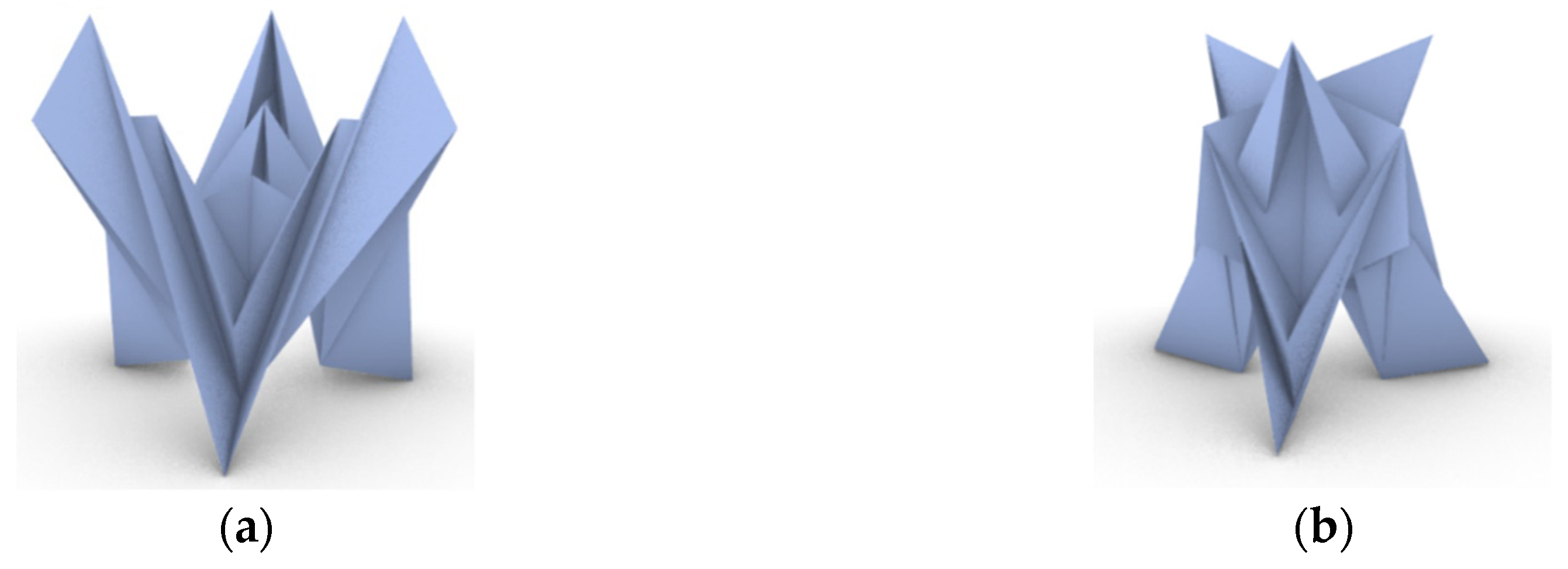
3] such as electronic circuits, sensors, antennas, and biomimetic constructs (
Figure 1). On the macro scale, the idea of folding and bending inspires people to design novel kinetic systems for architectural applications [
4], especially for those applied in space exploration, including various booms [
5] and expandable bases on Moon or Mars [
6]. Besides, this novel idea is conducive to the development of new materials [
6] that are practicable in folding and bending.
With a long history, origami functions not just as an art form, but as an inspiration for engineering and mathematics as well. Origami using non-singular patterns includes various types of folding methods that have one single mid-point and can be divided into sub-patterns rotating around the mid-point [
9]. Tachi et al. summarized the rule of these patterns’ degree of freedom [
10,
11]. Miura predicted one configuration which was later named the developable double corrugation surface (DDC surface), also called Miura-ori [
12]. Its symmetry has been discussed by Sareh et al. [
13] and different kinds of derivation from Miura-ori were presented by Sareh and Guest [
14]. Their research has confirmed that this rigid fold pattern theoretically has a single degree of freedom [
15,
16]. Unlike Miura-ori, whose cells are an in-line arrangement to make the contraction and expansion in rectilinear directions, Resch-ori tessellation consists of regular-polygon cells arranged circularly [
17]. This idea can be applied to the configuration of free-form surfaces, but there are more difficulties in building this tessellation and keeping it stable. Besides, Tachi proposed an origami approach with the idea of tucking molecules to construct a desired polyhedral surface by folding a single sheet of material [
18].
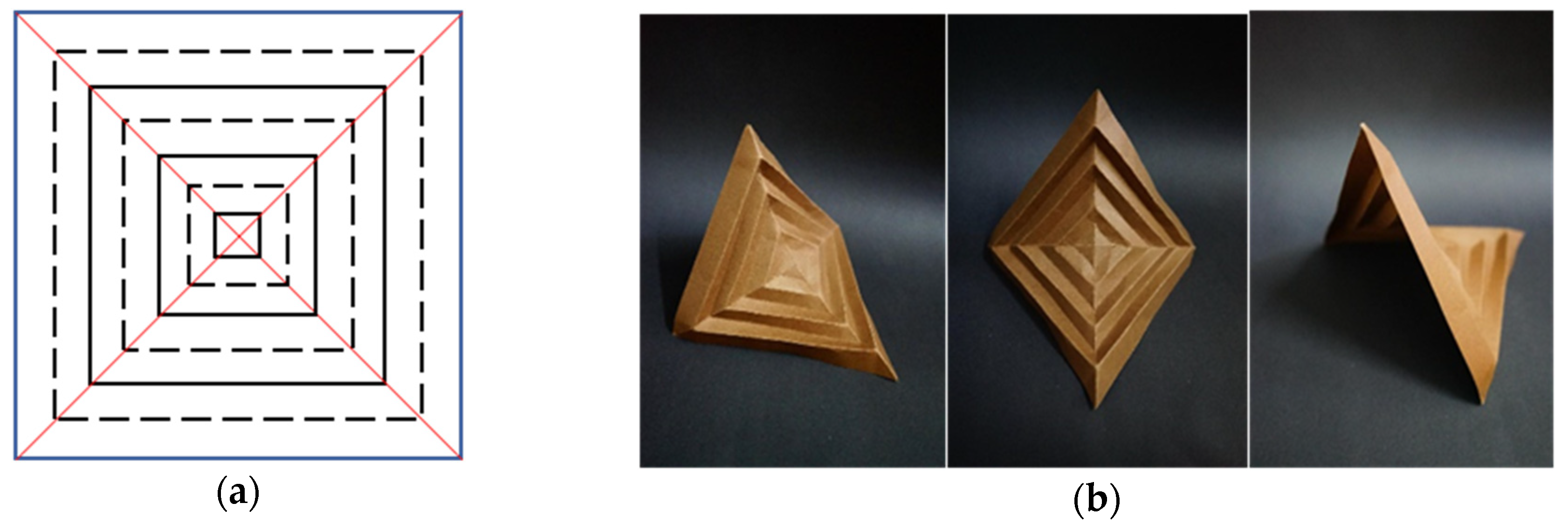
Concentric pleating, which also has a lot to do with symmetry, can be traced back to the Bauhaus School in the 1920s and its popularity was attributed to an origami artist named ThokiYenn. Structures following this pattern use sunk creases (valleys, which are presented as dotted lines in figures) and bulgy creases (mountains, which are presented as full lines in figures) alternately to build deployable negative Gauss surfaces. This pattern can be applied in regular polygons, as shown in
Figure 2, and even circular planes.
The negative Gauss surface obtained by concentric pleating is produced by torsion of a series of closed strip loops and these closed-loop creases generate a curved surface, while linear creases help build planar folding. Demaine et al. [
19] proved that it is impossible to achieve folds without stretching, tearing, or introducing additional creases because of the torsion inside each small trapezoid [
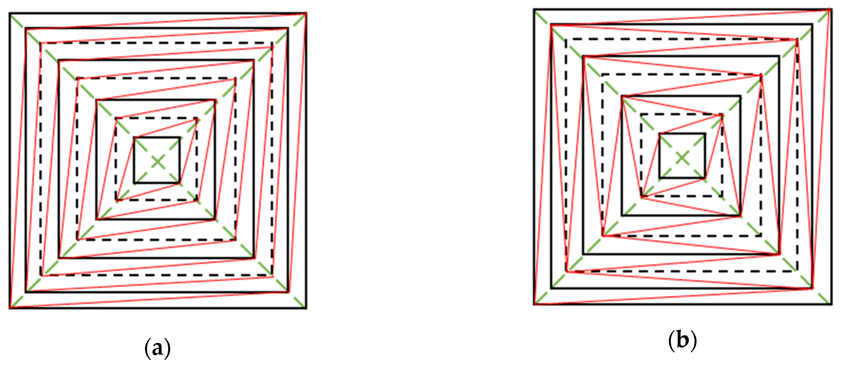
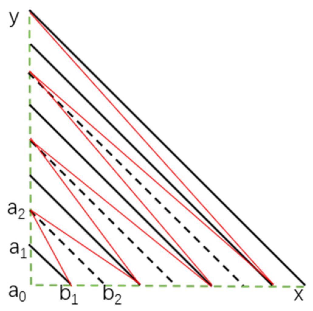
19]. They were inspired by Miura-ori to add one more crease inside each tetragon to obtain rigid folding, as shown in
Figure 3 (the black lines represent the original creases of which the full lines are mountains and the dotted lines are valleys, and the creases added into each tetragon are shown in red lines), and to create the two types of foldable triangulation.
Based on the properties of squares using concentric pleating, this paper chooses concentric pleating (alternating asymmetric triangulation), applies this pattern to the parametric modeling of regular hexagons and generalizes it to n-regular-polygons, because of its high folding efficiency. Following this, we analyze the efficiency, static performance and the rigid folding rule in this folding pattern. Finally, conclusions are drawn regarding the pattern of tessellation consisting of deployable regular polygons.
2. Concentric Pleating in Tetragons And Hexagons
2.1. Two Categories of Concentric Pleating
The concepts of “mountains” and “valley” also work on the standard crease pattern for concentric pleating, referring to different creases, as shown in
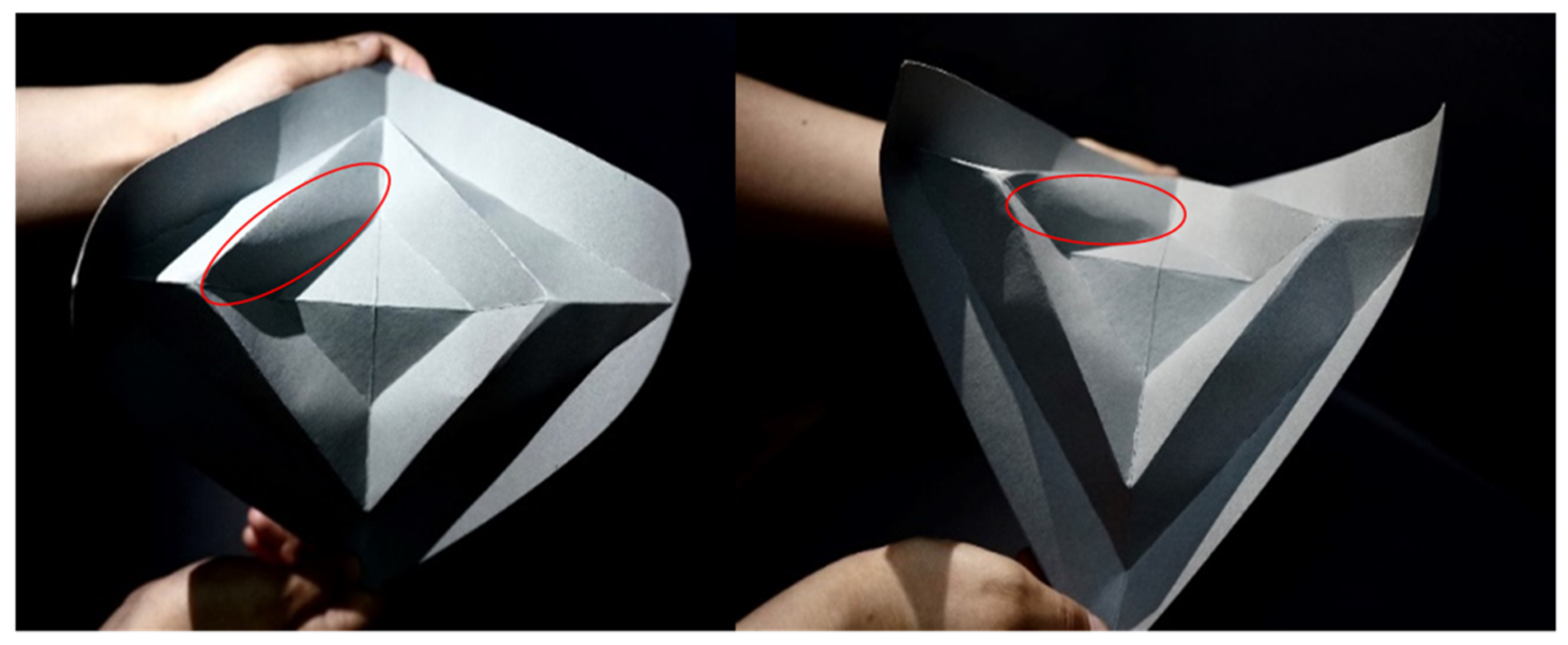
Figure 2, with two line-types. The standard folding pattern fails to obtain rigid folding and brings about additional creases, which are marked in
Figure 4, and stretching or tearing. It is obvious that when the fold angle θ reaches the limit, there will be torsion and buckling inside these trapezoids and the boundary lines show the maximum deformation. Inside every single trapezoid, the maximum deformation exists along its diagonal and this helps make a conjecture that if the trapezoid is divided by its diagonal into two triangles, it is probable that a rigid fold pattern exists.
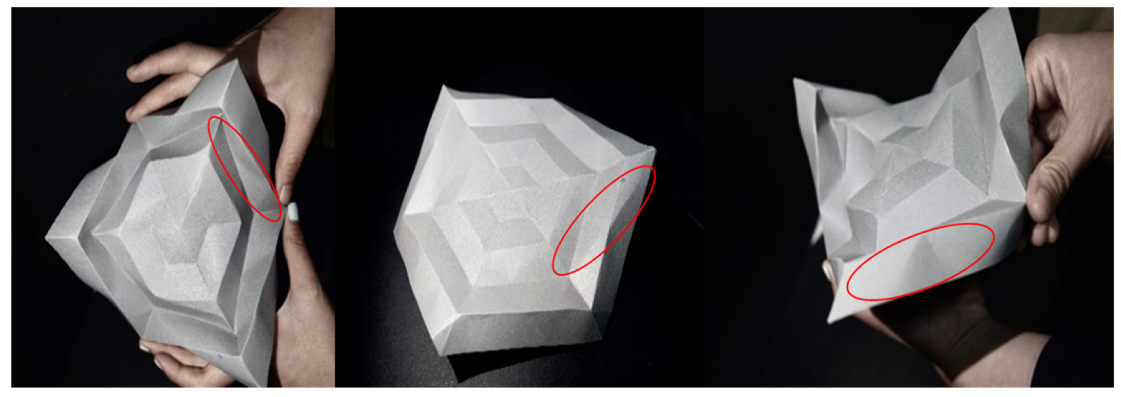
These properties also work in the concentric pleating of hexagons which leads to special negative Gauss surfaces and a non-rigid folding structure, as shown in
Figure 5.
It has been mentioned that triangulation is a possible approach to help realize rigid fold and Demaine et al. used it to propose two resolutions [
19] to this problem, called asymmetric triangulation and alternating asymmetric triangulation (
Figure 3). Within a certain range of the fold angle, there is no torsion or buckling, which means that triangulation is an effective way to obtain rigid folds of squares and this result also works on regular hexagons. Whether they are squares or regular hexagons, alternating asymmetric triangulation has higher folding efficiency than asymmetric triangulation, so in the following parts this paper focuses on the former method for further discussion.
The degrees of freedom (DOF) of alternating asymmetric triangulation conforms to the rule of Formula (1); thus, for regular tetragons, the degree of freedom is one and for regular hexagons, it is three.
2.2. Parametric Modeling
2.2.1. Geometrical Relationship in Squares
Here, the geometrical properties of squares using alternating asymmetric triangulation are reviewed.
It is assumed that one diagonal of the central square is fixed on the y-axis and points a
i and b
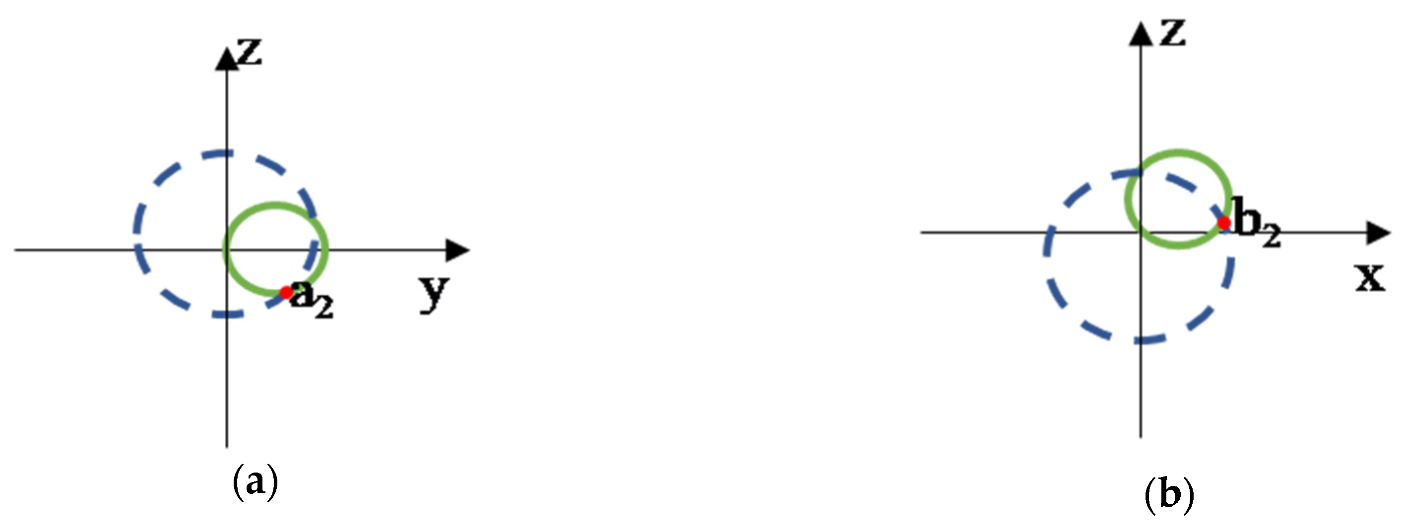
i (i = 1,2,…) will move on the Y–Z plane and X–Z plane, respectively. Here, the way this paper finds these vertexes will be illustrated with examples of a
2 and b
2, as shown in
Figure 6. The width of one loop is defined as d, so the length of these creases are
A sphere is modeled whose center is a1 and the radius is the length of a
1a
2, while the intersection of the sphere and Y–Z plane is a circle. Similarly, there is a sphere of radius a
2b
1 centered at b
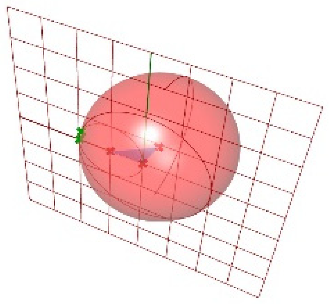
1 intersecting with the Y–Z plane so that another circle is obtained on this plane, as shown in
Figure 7.
The intersection of two circles will be two different points, one single point or nothing. Here we assume that there must be one or two points in the intersection of these two circles on the Y–Z plane. If the solution is one point, then this solution is the genuine one, the coordinates of a
1. When there are two different solutions, as shown in
Figure 8, the real solution can be easily confirmed because this surface has a saddle-shaped configuration and if a
0a
1 is fixed, then a
1 must be below the X–Y plane, which means that its y coordinate is a positive number. By this approach, the coordinates of b
2 are at the intersection of two circles on the X–Z plane. The two circles are intersections of two different spheres of radii a
2b
2 and b
1b
2 centered at a
2 and b
2, respectively, and this saddle-shaped surface makes this point b
2 located above the X–Y plane. Demaine et al. used the mountain-valley assignment to determine the genuine solution and propose an algorithm based on Mathematica’s fully expanded solution for the general case to obtain this structure [
10].
The coordinates of other points can be calculated step by step and the location of b
1 is only decided by the folding angle, which is the basic parameter. When the sub-plate is completed, the whole plate can be constructed by copying the sub-plate itself, as shown in
Figure 9.
2.2.2. Geometrical Relationship in Regular Hexagons
Since former researches mainly focus on the alternating asymmetric triangulation of squares and have given narration on the modeling [
19], this paper generalizes this triangulation to regular hexagons and even n-regular polygons. However, this differs from the modeling of squares. In the demonstration before, it is clear that
a0a1 can be assumed as fixed, while for regular hexagons only the mid-point can be regarded as an immobile one, which leads to a new geometric relationship.
In the initial state, the whole plate is flat and the following part illustrates some eternal geometric rules to help the construction of the parametric model. The design process mainly focuses on the geometrical relationship in a sub-plate and the final crease pattern can be created by symmetrically coping itself.
During kinematic motion, the distances between each pair of adjacent points are fixed, which this paper makes use of to build the model. In a regular hexagon, the central point,
a0, is permanent, and to obtain the coordinates of the other points there are some rules that can be followed [
19].
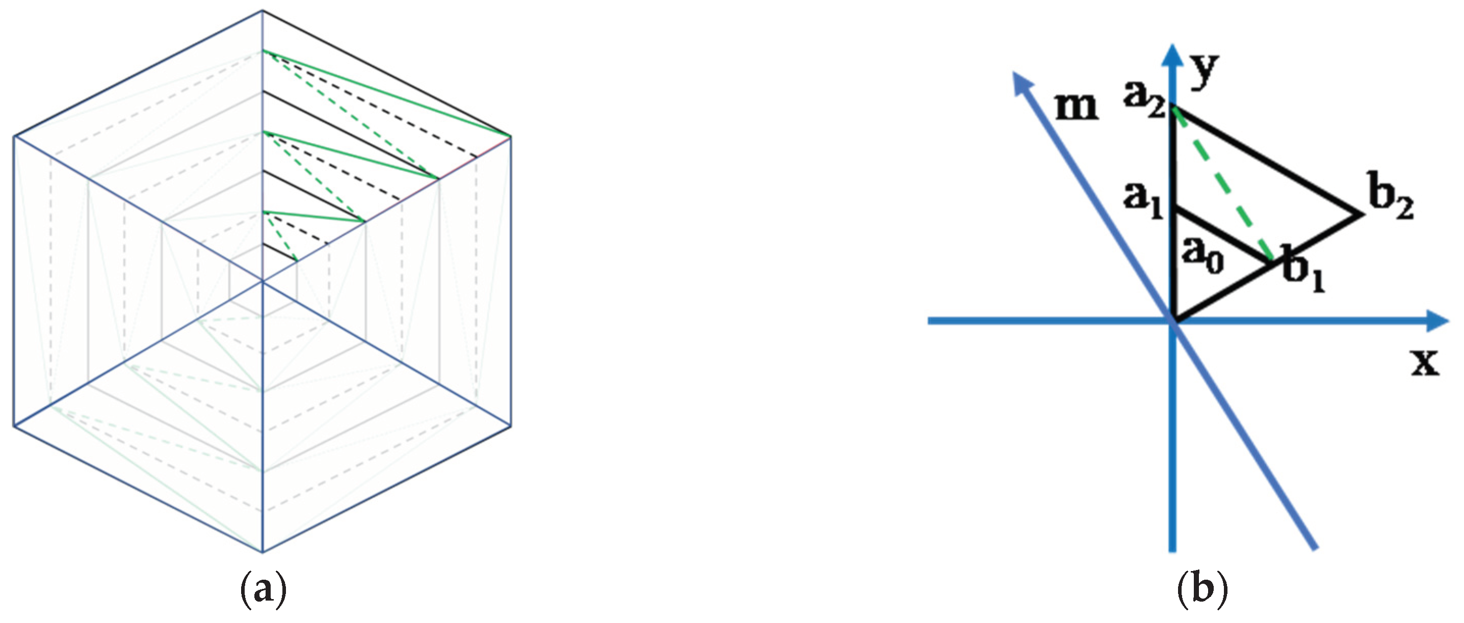
In
Figure 10, it is assumed that the mid-point
a0 is fixed at the original and
ai (
i = 1,2,…) is moving within the Y–Z plane. The point b
1 is regarded as rotating around the m-axis, the angle between this and the y-axis being 30°. Thus, the folding angle refers to the angle that
a0b1 is rotating around the m-axis and, once the angle is given, the length of
a0b1 can be derived from d and the regular triangle’s geometric properties.
These distances are immobile, so the coordinates of
ai and
bi are derived from them. This paper assumes that the initial state is when the paper is a flat sheet without deformation, as shown in
Figure 11. Once the location of
b1 is obtained, a sphere with the radium of
a1b1, whose center is
b1, will intersect with the Y–Z plane to generate a circle on this plane. Then,
a1 is the solution of the intersection of this circle and another one which is centered at
a0 with a radius of
a0a1 on this plane. When there are two solutions in the intersection, the genuine solution must follow the rules of a negative Gauss surface, as mentioned in
Section 2.2.1. This process is shown in
Figure 12.
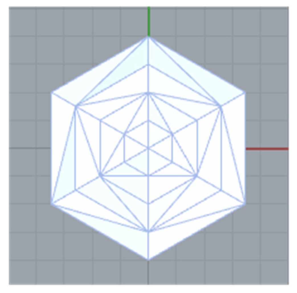
After confirming the positions of the first triangulation of a hexagon, the following points’ coordinates can be calculated with similar methods by intersecting several spheres, as shown in
Figure 13.
Figure 14 illustrates the process after one sub-plate of a hexagon is completed, where the symmetry of a regular hexagon with alternating asymmetric triangulation will help finish the model.
These ideas about kinematic motion can be generalized to n-regular polygons for parametric modeling.
2.2.3. Parametric Modeling of Deployable Structures Based on Alternating Asymmetric Triangulation
Parametric modeling is a process that transfers the design itself into functions, and by adjusting the initial conditions these functions will automatically compute the results. Tachi et al. developed three programs named Rigid Origami Simulator [
20], Orimamizer [
21,
22] and Freeform Origami [
23] to help design origami approaches. This paper utilizes the Kangaroo [
24] plugin in Grasshopper [
25], developed by Daniel Piker, to build the parameterized models of these structures in the digital environment of Rhinoceros [
26] according to the ideas above. Grasshopper is a graphical algorithm editor tightly integrated with Rhinoceros’ 3-D modeling tools for designers who are exploring new shapes using generative algorithms. Meanwhile, Grasshopper and Rhinoceros combined together can realize visual modeling, which is within the trend of intellectualized design. Kangaroo is a Live Physics engine for interactive simulation, optimization, and form-finding directly within Grasshopper.
For the models discussed in this paper, the basic parameters are the fold angle of the central square, the width of each closed-loop, the number of edges of the polygons. According to Tachi [
9], when the number of edges and the width of loops are fixed, the coordinates of vertices are available, so in the process of parametric modeling, this paper chooses the fold angle of the central square as the basic parameter. As shown in
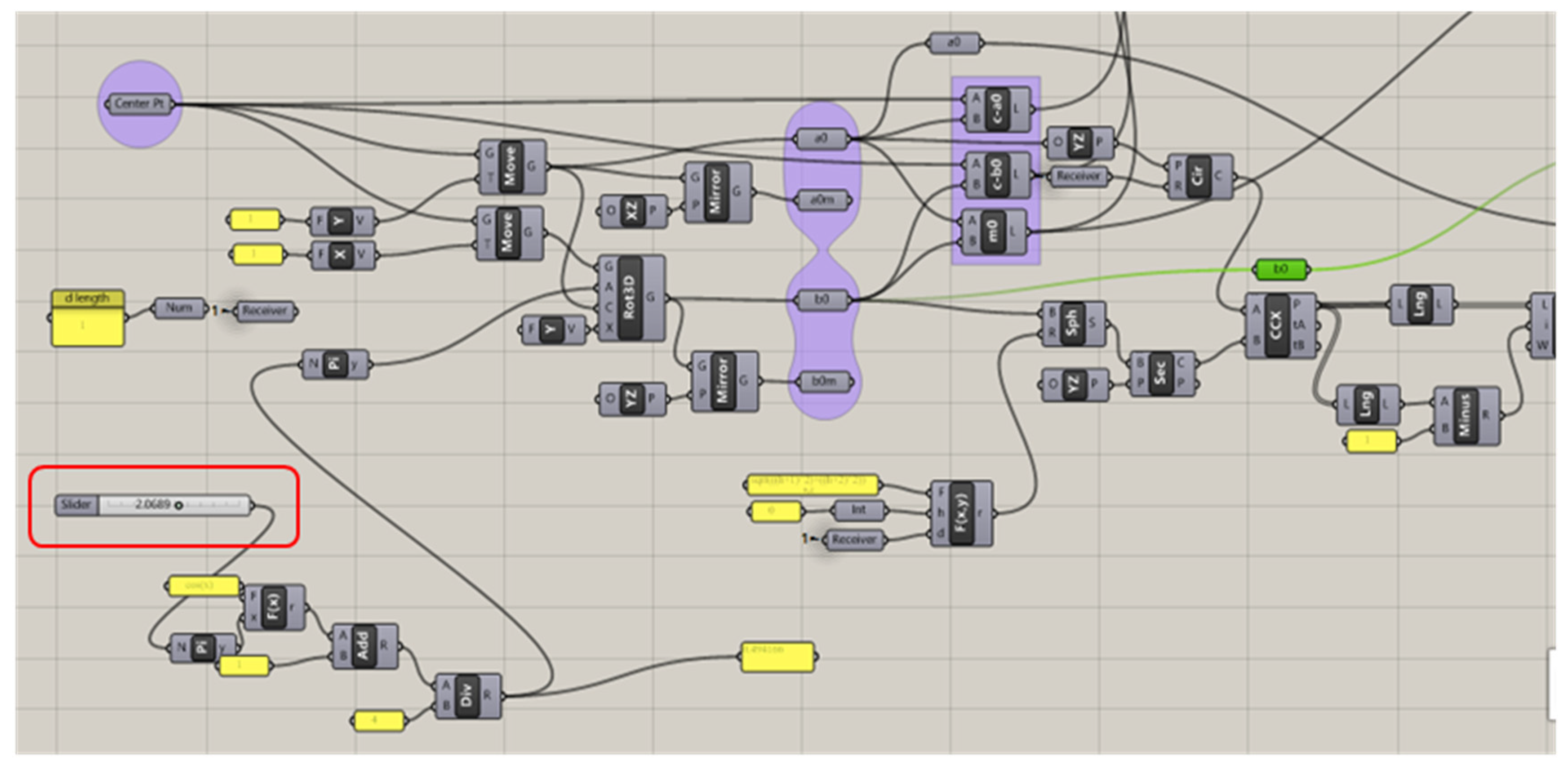
Figure 15, by adjusting one parameter related to the folding angle, the bar marked in
Figure 15, the whole condition of this model can be changed. The specific model built in Grasshopper is presented in
Appendix A.
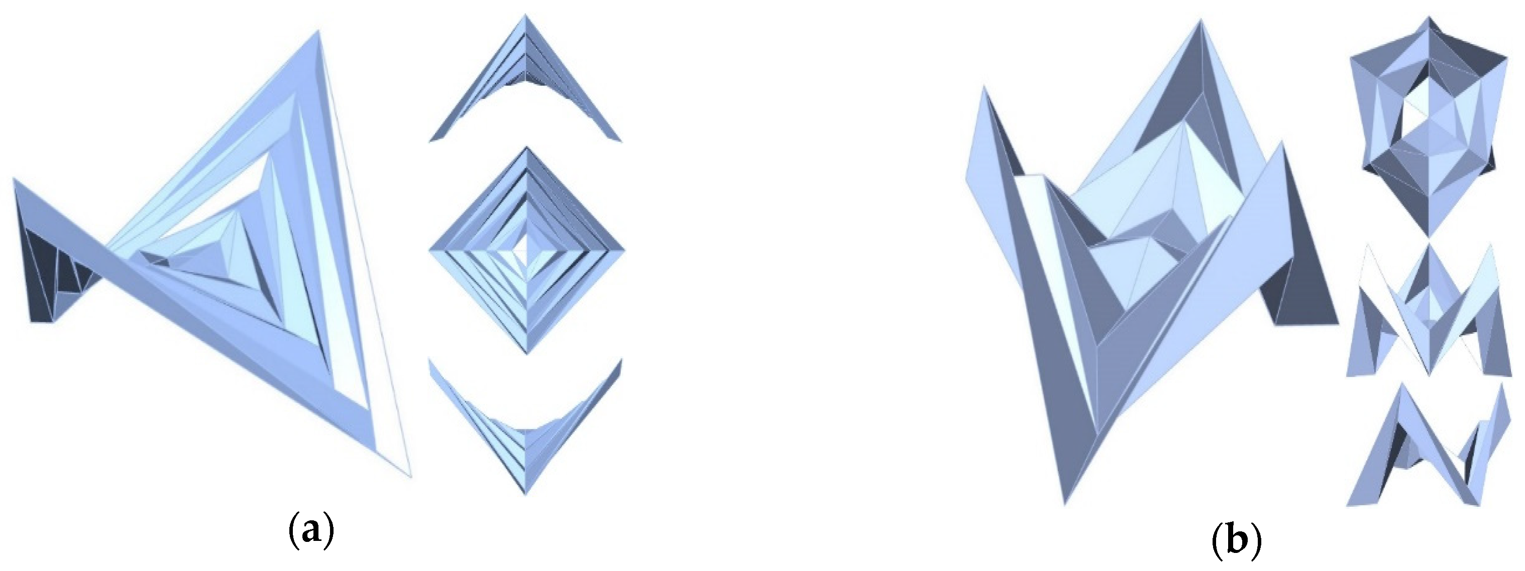
The parametric model of squares and regular hexagons using alternating asymmetric triangulation is shown in
Figure 16.
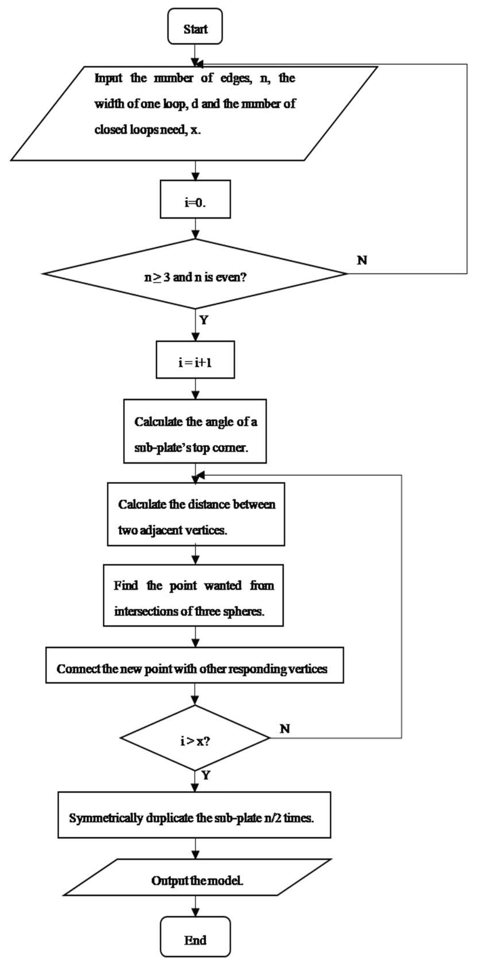
In addition to modeling of squares and regular hexagons, the parametric modeling of n-regular polygons using alternating asymmetric triangulation is possible. Though there are some subtle differences among polygons with various number of edges, the geometric relationships among vertices and creases can be derived through the geometric properties. Here, this paper summarizes and gives the flow diagram of parametric modeling for the n-regular polygon, as shown in
Figure 17.
2.3. Analysis of Kinematics Motions
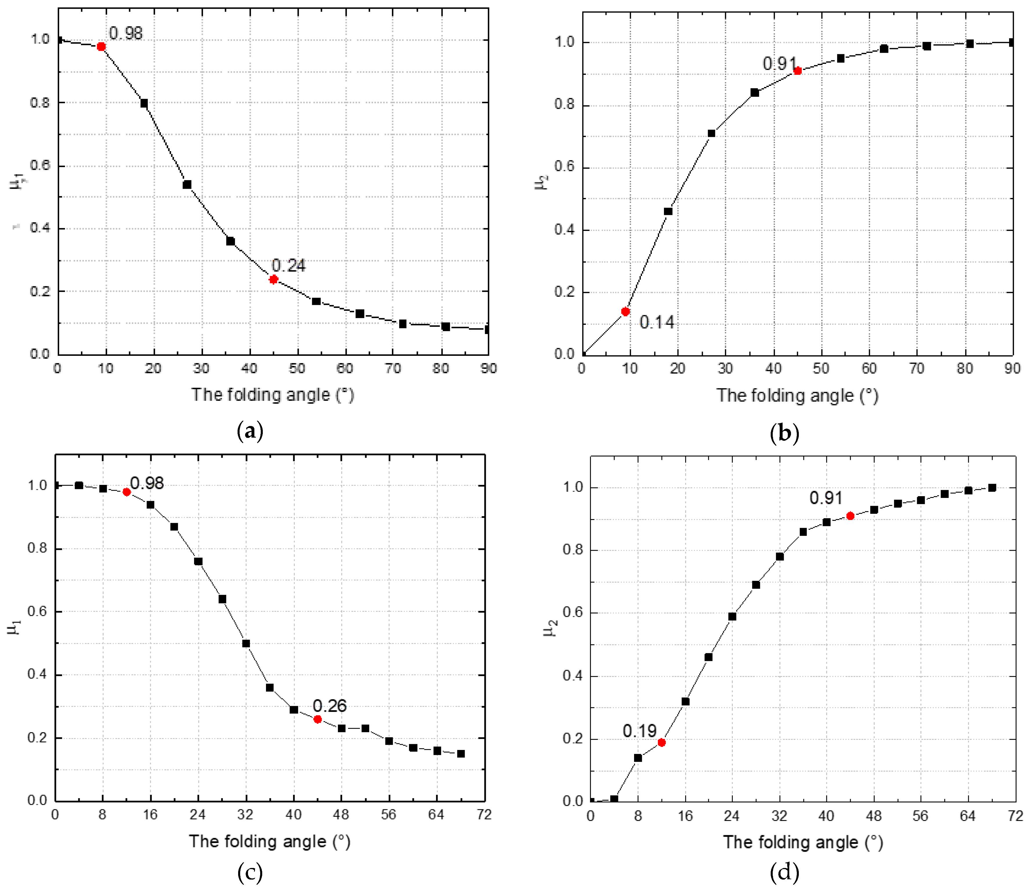
To obtain the kinematic properties and the folding efficiency of alternating asymmetric triangulation, it is necessary to analyze deployable structures’ kinematic motions. Using the models constructed in the platform of Rhinoceros, this paper will discuss the variation trend of the projected area of the top view and the height of the side view. This paper defines the maximum projected area and the maximum height during the process of deployment as the reference values to normalize these variables. The results are shown in
Figure 18, and
μ1 and
μ2 are defined as following to make it clearer:
where
A1 refers to the projected area of the top view,
A2 is the maximum projected area,
H1 is the projected height of the side view, and
H2 is the maximum projected height.
It can be concluded that the relationships are obviously nonlinear for the surfaces as Gauss surfaces using these results for reference and observing the data from parametric analysis. The graphs of a regular tetragon show the characteristics of quadratic lines and the graphs of a regular hexagon demonstrate similarities with cubic curves.
Specifically, during the deployment of squares, the projected area of the top view experiences a sharp decline when the fold angle, θ, is around 10°, and then a less steep decline around 45°; the same applies to hexagons. Consequently, it is possible that this trend is determined by this pattern’s geometric properties and has nothing to do with the number of edges of the plate. Furthermore, it is likely that an n-regular polygon applying alternating asymmetric triangulation will illustrate these trends as well and the number of edges just affects the maximum fold angle. The more edges this plate has, the lower the fold angle it can reach.
2.4. Rigid-Foldable Origami
The research of Fushimi et al. [
27] about the rigid-foldable origami of zero-thickness paper leads to the famous Fushimi Theorem, which shows the condition of angle that the folding pattern has to meet. From the crease patterns shown in
Figure 3b and
Figure 10a, the numbers of creases meeting in one vertex varies at different points, which is alternately four or six in the first closed loop in a square or a hexagon, and compared with the similar topological relationship, the variation follows some rules. It is obvious that the number of regular polygons’ edges has to be even if the alternating asymmetric triangulation is feasible.
Table 1 gives the distribution regularities of the number of creases in one single vertex in different regular polygons whose number of edges is even.
Through further study, it is found that when the point has a four-crease pattern, among the four creases, there will be three mountains and one valley, or three valleys and one mountain; when it is the six-crease pattern, there will be four mountains and two valleys, four valleys and two mountains. If there are eight creases meeting at one point, these creases always consist of five mountains and three valleys, or five valleys and three mountains. The regularity in the four-crease pattern is the aforementioned Fushimi Theorem.
4. Conclusions
The aim of this paper is to illustrate the geometric properties of concentric pleating based on alternating asymmetric triangulation and make use of these characteristics to realize parametric modeling of this folding pattern. During the whole process of kinematic motion, the distances between two adjacent points is immobile, so the authors take advantage of this property to find a feasible and convenient way to generalize the parametric modeling from squares to regular hexagons, using the intersections of some spheres and planes to obtain the coordinates of all the points successively. Though there exists some difference between the motion of squares and that of hexagons, the overall concepts are the same and can be generalized to n-regular polygons in this paper.
These models can be constructed parametrically in the digital environment of Rhinoceros, using Kangaroo in Grasshopper, so that designers can directly observe a model’s kinematic deployment and calculate the folding efficiency. The authors make use of the convenience of modeling using Kangaroo in Grasshopper in the environment of Rhinoceros to obtain the maximum foldable angle both for a single polygon and their tessellations. The folding of one single polygon limits the tessellation of several polygons and the available folding angle will be around one-third of that of a single polygon, which diminishes the folding efficiency. Besides, this paper makes conclusions that the tendencies of folding efficiency in different regular polygons are not the same: In squares, the graph is a quadratic line, while in regular hexagons it is a cubic curve. To maintain the rigid folding, each polygon has a limit folding angle, beyond which there will be stretching or teasing within the paper. Meanwhile, the number of creases meeting in each vertex also follows some rules, as shown in
Table 1.

