1. Introduction
A field of interest in tissue engineering (TE), the discipline whose main aim is to replace damaged tissue and organs, relates to bone repairing [
1]. Porous biocompatible structures, generally termed as engineering scaffolds, can be used as bone replacement when other procedures, such as autologous bone grafting, are not feasible or involve high risk for the patient. Engineering scaffolds have to provide an optimum environment for cells to develop and culture into tissues meeting biological, physical, and mechanical properties of the replaced tissues.
Thus, at the design stage, different parameters have to be considered to accomplish the requirements. The performance of a scaffold usually depends on an optimal combination between the dimensional and geometrical characteristics of the pores and the resultant mechanical properties of the structure. Generally, large and interconnected pores are preferred for bone ingrowth leading to structures with high porosity; on the other hand, the mechanical properties have to be similar to those of the bone to avoid mismatches with the surrounding tissues which can affect the operation or longevity of the implant as a result of the effect known as stress shielding [
2].
The choice of a proper material is another significant issue in the design of the scaffolds, since, besides the intrinsic mechanical characteristics, the biocompatibility is a fundamental aspect to be taken into account. Biodegradable polymeric materials have been considered [
3] to facilitate cell ingrowth due to material resorption over time along with the adequate mechanical environment provided by the structure of the scaffold. For load bearing applications investigated in this study, biocompatible metallic scaffolds are expected to fulfill the required mechanical strength. In particular, the use of titanium and its alloys, such as Ti-6Al-4V, is well reported in literature [
4,
5,
6] since they have an excellent strength-to-weight ratio, toughness, and most importantly, the biocompatibility and corrosion resistance of their naturally forming surface oxide [
7], making them particularly suitable for these applications.
The advent of new manufacturing technologies, such as additive manufacturing (AM), has expanded the potentiality in the design of these structures since with these techniques, tailored design specification implants and highly complex and custom-fitting medical devices can be provided [
8].
The modelling of these structures can be conducted with different approaches. The simpler approach uses parametric Computer-Aided Design (CAD) modelling in which a unit cell is generated from solid features that are combined together. A three-dimensional (3D) periodic array of the unit cell can be carried out along three mutually perpendicular directions to obtain the final architecture. Usually, lattice-based geometries [
5,
6,
9] such as cubic, diamond lattice, rhombic dodecahedron, or similar, are generated with this method since more complex geometries are difficult to model.
Another approach, which was used in this paper, is the method of implicit surface modelling (ISM). ISM is a highly flexible approach for the generation of cellular structures providing a compact representation of potentially complex surfaces. It allows the description of scaffold architectures using a single mathematical equation, with the capability to introduce different pore shapes and architectural features, including pore size gradients [
10].
This method was used to model scaffolds based on the class of surfaces known as triply periodic minimal surfaces (TPMS). These surfaces, frequently occurring in nature, are considered very attractive for these kind of applications [
11,
12]. They are, mathematically, defined as surfaces with zero mean curvature at every point and periodicity in three directions mutually perpendicular [
13]. Structures based on these surfaces, have shown to provide high values of permeability [
14], parameter related to geometrical characteristics such as pore shape and size, high surface to volume ratio, and topological complexity for cells ingrowth. Furthermore, it has been shown [
15] that their curved configuration can promote cell proliferation more than scaffold architectures based on lattice cells. Lattice based architectures are well reported in literature and they have been studied both experimentally and numerically. The scaffolds based on TPMS surfaces can be potentially advantageous compared to those for the properties abovementioned. Moreover, the lattice-based architectures are characterised by the presence of sharp corners that should lead to stress concentrations; the curved surfaces of the scaffolds based on TPMS surfaces should contribute to attenuate this effect.
Among the various TPMS surfaces that have been described, the level surface known as Schwarz’s Primitive (P) minimal surface has been considered in this study. Examples of applications of this surface to scaffold design is more limited in literature with respect to other surfaces belonging to this class such as Gyroid [
16] or Diamond [
17].
Starting from the basic equation of the surface and by considering various parameters that are varied within suitable ranges, solid models of the cells can be obtained. Scaffolds with uniform geometrical characteristics can be obtained with the procedure previously described for lattice-based architectures, that is, by replicating a unit cell along three orthogonal directions.
Most of the structures reported in literature are arranged in this way. In addition, scaffolds whose characteristics locally vary, for example, with a linear gradient of porosity along one or more directions, can be obtained with the combination of cells with different geometrical configurations resulting in structures with a more complex architecture with respect to those with a uniform arrangement.
Scaffolds in which either porosity or pore architecture vary throughout the structure are of particular interest, since they can facilitate the optimisation of different, and sometimes conflicting, requirements. In fact, generally, high porosity supports more cell growth and penetration but it limits the load bearing capability of the scaffold. Furthermore, this arrangement is more similar to that of real bone which is intrinsically stochastic, although the configuration and the porosity distribution is different in the various zones of the human body.
Different approaches can be used to model structures with variable architectures. Scaffolds with uneven structural configurations can be obtained by assembling unit cells arranged in a library by using programmed algorithms [
18] or by using mathematical expressions that are manipulated operating on the terms related to the porosity domain [
19,
20]. In Reference [
21], geometrical and topological information on the bone tissue are obtained from medical images; the complex geometry is then partitioned into functionally uniform regions to generate structures with gradients of porosity.
In this paper a method based on ISM has been implemented and scaffolds with variable pore architecture were modelled. These structures are based on the TPMS Primitive (P) cell whose geometrical characteristics were locally varied so as to obtain the different architectures. The characteristics of a scaffold in terms of distribution of the porosity should be chosen according to the specific function the implant has to carry out. From this perspective, scaffolds with a linear gradient of porosity in a direction and structures with a radial gradient, or similar, are of interest. These types of scaffolds were considered in this study and structurally analysed in relation to a scaffold obtained with a P-unit cell replicated in the 3D space. The numerical evaluation of the modelled scaffolds was done by means of finite element analysis (FEA) considering the structures made of a biocompatible titanium alloy and were subjected to compression load. In this way, the geometrical configuration of the structures considered was related to the mechanical response in terms of strength and stiffness.
2. Methodology
The methodology proposed here for scaffold modelling was based on surfaces suitably derived from the Schwarz Primitive, which belongs to the class of the minimal surfaces. Several approaches exist for modelling the minimal surfaces. These approaches are: parametric, implicit, or based on boundary methods. In the parametric approach, the minimal surface is described by a parametric equation. However, only a few minimal surfaces can be described with simple analytical functions in Cartesian space, such as, for example, the catenoid or the helicoid [
22]. Minimal surfaces can be generated parametrically using the Enneper–Weierstrass representation. However, since the Weierstrass function is known only for a few minimal surfaces, the parametric method is generally not used for describing this class of surfaces [
15].
Boundary methods include a number of approaches aimed at the modelling of discrete TPMS. These methods are based on the progressive refinement of a first polygonal model defined by its boundary, subjected to a variety of boundary and inter-polygonal constraints [
15]. In the Plateau method (1873), a polygon in R
3 is iteratively refined to minimise the area of the polygonal mesh spanning the boundary. This refinement continues until no single vertex of the triangulation can be moved further to decrease its area. The phase-field is another boundary method allowing the generation of a triply periodic surface with a constant mean curvature satisfying a constraint on the volume fractions of the regions that the surface separates.
In this paper, as stated in the introduction, the implicit method is used for the modelling of the scaffolds derived from the Schwarz Primitive. Using this approach, the surface of the scaffold is described by means of an implicit f that is a continuous scalar-valued function over the domain R
3. The minimal surface is then defined as the locus of points at which the implicit function f(x,y,z) takes a zero value. Since any periodic surface can be described by the sum of an infinite number of Fourier terms, a surface derived from the Schwarz minimal surface (P-surface in the following) can be described, to the first order of approximation, by the following nodal equation:
The two mathematical parameters,
s and
k in Equation (1), can be used for modifying the architecture of the P-surface. Under the boundary conditions
x = [−π, π],
y = [−π, π] and
z = [−π, π], theP-surface described by Equation (1) delimits a single cell with cubic symmetry of side 2π (
P-cell in the following). When in Equation (1)
k = 0, the P-surface is a minimal surface satisfying all the properties of this class of surfaces. When
k is non-zero, the P-surface is characterised by a constant value of the mean curvature at each point, and it partitions the 3D space into two phases, no longer having the same volume. If the two phases respectively identify a solid and a void region, this last observation implies that the P-cell is characterised by a porosity different from 0.5.
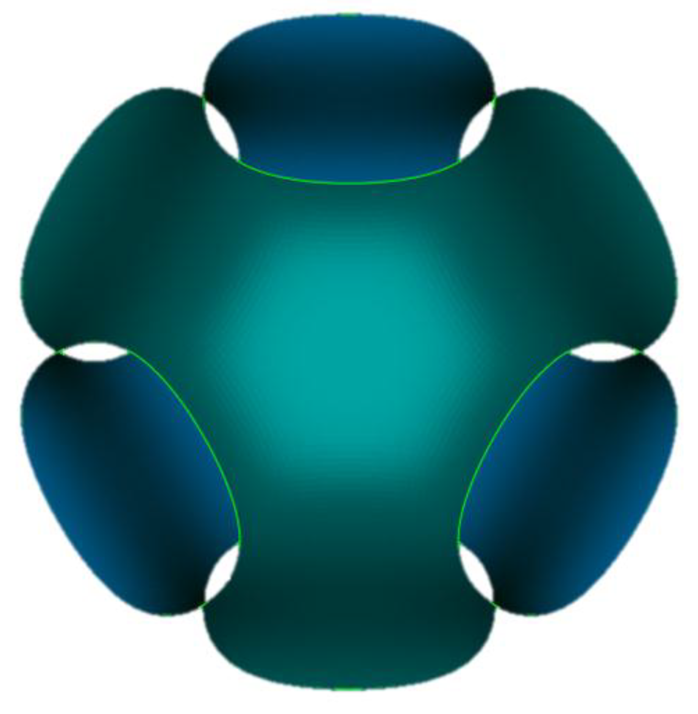
Figure 1 shows the Schwarz minimal surface which is obtained setting
k = 0 and
s = 1 in Equation (1).
In
Figure 2, different models of P-cell are represented for
s = 1 and at the varying of the
k parameter. In this figure, the surface in red is the P-surface shown in
Figure 1 and the
k values increase going inward.
The variation of the parameter s in Equation (1) has the same effect of a scaling transformation (uniform if the s-value is the same along with the directions x, y and z) with respect to its barycenter followed by the intersection of the scaled surface with the cubic cell.
In
Figure 3a,b, different models of the P-cell with
k = 0 are shown by varying the
s parameter (the
Schwarz Primitive is always in red).
Figure 3a shows the P-cells obtained for
s ≥ 1.
Figure 3b reports the P-cells for
s ≤ 1; in this case, to point out the geometrical differences among the various cells, a sectional view of the surfaces is shown.
When k or s are varied in Equation (1), some important geometric properties of the cell also vary, such as porosity, pore size, area-volume ratio, and so on. These properties are directly related to the target requirements for the design of customised bone scaffolds. A solid model of the P-cell can be obtained from the tessellated surface by an operation of offsetting that makes the P-isosurface solid. The geometry of the solid P-cell is influenced not only by the parameters k and s of the mathematical formulation of its most external surface, but also by the thickness t added during the offsetting operation.
The scaffolds modelled in this study are described by an implicit function similar to Equation (1), where k is a continuous scalar-valued function over the domain R3. For a cubic scaffold with a number of cells along one side equal to N, the domain of the function is given by the boundary conditions: x = [−Nπ, Nπ], y = [−Nπ, Nπ], and z = [−Nπ, Nπ].
The functions for
k that have been considered in this paper are shown in the right column of
Table 1 (where
C is an arbitrary constant) and identify different types of scaffolds, as reported in the left column of the table.
In
Figure 4, P-surface with
s = 1, N = 7 and a quadratic function for
k (with
C = 0.002) is shown.
In particular, this surface represents the most external face of the scaffold designated as ‘
quadratic’ in
Table 1.
The value of the constant C has been established to balance the two following opposite requirements:
- -
the gradient of k function along x and y must be as large as possible;
- -
the values of k function must be such as to preserve the integrity of the P-cell and that of its lateral openings. This requirement is essential to allow the cells to gradually and progressively populate the ducts of the scaffold, regenerating the bone tissues. The satisfaction of this aspect requires that ranges of variability, suitable for the two parameters k and s, are identified. Since in this paper s has been assumed equal to 1, k must vary between −1 and 1 into the function domain identified by the boundary conditions x = [−7π, 7π] and y = [−7π, 7π].
An algorithm, based on MATLAB functions for implicit surfaces representation, carried out the P-surface modelling, described in the form of tessellated model (STL model). Along the diagonals of the top view of the surface, the P-cells are very close to the
Schwarz Primitive of
Figure 1. Furthermore, the porosity and the pore size of the cell increase quadratically along the
x-axis and decrease, with the same law, along the
y-axis.
Starting from the P-surface of
Figure 4, a solid scaffold was modelled according to a procedure whose main steps are reported in
Figure 5.
The P-surface was firstly scaled to obtain a cubic cell of assigned side (
Figure 5a). Then, the internal face of the scaffold was generated starting from the external one by an offsetting operation with offset distance equal to the thickness
t (
Figure 5b). In order to obtain a scaffold with a given number of cells, several planar cuts were performed along the three directions
x,
y, and
z. In
Figure 5, for example, these planar cuts resized the quadratic scaffold, bringing it from N = 7 to N = 5. Finally, the scaffold was converted into a solid structure (
Figure 5c). These steps, aiming at achieving the final structure of the scaffold, were performed in a CAD environment by CATIA software.
A similar procedure was used to obtain the other structures.
3. Results and Discussion
The methodology described in the previous paragraph was used to obtain representative models of scaffolds with different geometrical characteristics.
A preliminary analysis was conducted on unit P-cells starting from Equation (1). By considering the parameters k and s previously discussed, solid cells with different geometrical configurations were finally obtained. Their characterisation in terms of geometrical properties and performance under load provided useful information, mainly in relation with porosity and stiffness of the different geometries, for the development of the scaffolds.
The 3D models were made of 5 × 5 × 5 cells. Previous studies [
23,
24] have shown that many properties of a porous scaffold and, in particular, the elastic modulus, can be numerically predicted by considering a lower amount of unit cells, rather than the whole structure. It has been shown that there is no benefit to model structures greater than 5
3 cells; in fact, the difference between the value of convergence of the simulation and the calculated value is, in percentage, negligible. The models made of a limited number of cells provide the additional benefit of reduced computational cost in the Finite Elements FE simulations compared with larger models.
The value of the thickness assumed for the models was 0.240 mm. The selection of this parameter is related to the range of values of high porosity suitable for the scaffolds. The choice of modelling structures by introducing a constant thickness into the surface of the P-cells, instead of considering solid models made with P-surfaces entirely filled in the inner portion, as reported elsewhere [
20], has the advantage to increase the interconnectivity of the cells which is desired for tissue growth. Furthermore, in all the modelled structures, a limited gradient of porosity was introduced in order to avoid abrupt changes between adjacent cells.
The first configuration considered was relative to structures with a linear gradient of porosity along the vertical direction. This is a property that should be desired for some applications, such as linkage replacement, to mimic the incipient tissue.
Figure 6 shows a linear model with a gradient along the vertical (
z) direction equal to 0.05.
In this model, cells with lower porosity are located at the bottom portion of the model while those with the largest values are obtained at the top. The porosity of this structure varies between 0.88 and 0.91.
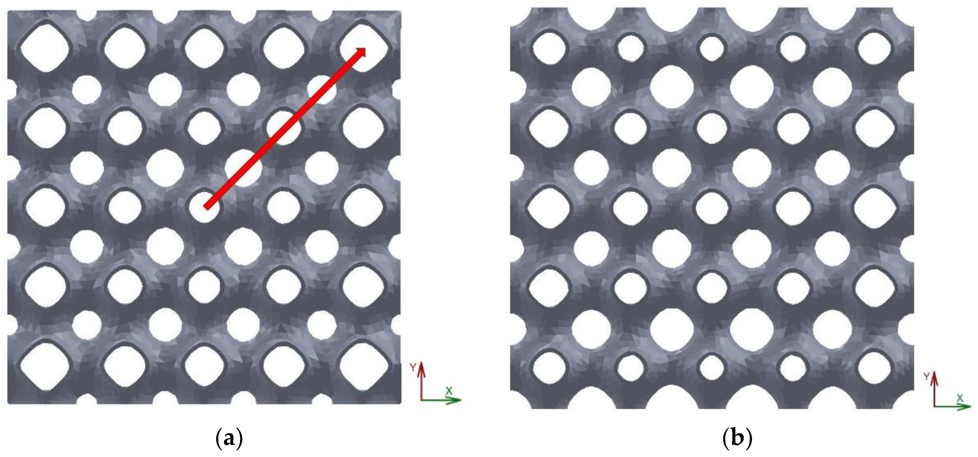
Two other representative models made of 5 × 5 × 5 cells are reported in
Figure 7.
The scaffold in
Figure 7a is relative to a structure corresponding to the radial configuration as defined in
Table 1. This structure is characterised by the presence of the cells with larger values of porosity at the outer part leading to a configuration that should be interesting to attribute to the peripheral areas bone ingrowth while the central areas should accomplish the load bearing, for example, when the scaffold is designed to fill in cylindrical voids. The structure reported in
Figure 7b is relative to a scaffold with a quadratic architecture, as mathematically defined in the previous paragraph.
The models of the scaffolds were analysed with FE numerical simulations conducted on the commercial software Abaqus. The material chosen was a titanium alloy (Ti-6Al-4V), a material with biocompatible properties, frequently reported in literature for bone implants. The mechanical properties are assumed as: E = 110 GPa, ν = 0.3.
Brick linear elements were used for the discretisation of each structure. It has to be observed that the models of the scaffolds based on the P-cells are characterised by the presence of curved surfaces whose discretisation, to obtain affordable results, requires a mesh with a large number of elements. To limit the computational effort, a quarter of each model was considered and symmetry boundary conditions were applied to simulate the whole structure. A sensitivity analysis was performed for an optimal compromise between accuracy and computational time which conducted to meshes of about 2,500,000 elements.
The models were subjected to a uniaxial compression load. In particular, the tests were performed by applying a uniform displacement, within the material elastic limit, to the top surface of the structure corresponding to 0.1% of the compressive strain, while the lower surface was fully constrained.
The first model analyzed was the structure reported in
Figure 6, which is characterized by a linear gradient of porosity along the z direction. The uniaxial compression load was applied in the direction of the gradient (z).
Figure 8 shows an iso-colour representation of the compressive stress, expressed in MPa, obtained for this model.
In the figure, both the 3D representation of the compressive stress distribution and a frontal view are depicted. The figure shows, qualitatively, a non-uniform distribution of the compressive stress along the structure, which can be explained in relation to the distribution of the porosity. Wider areas of compression stress, with respect to the areas of tensile stress, are identified in the upper layers where the cells with larger values of porosity are located. On the other hand, in the lowest layer of cells, where the porosity takes the lowest value, these areas are more comparable in terms of extension.
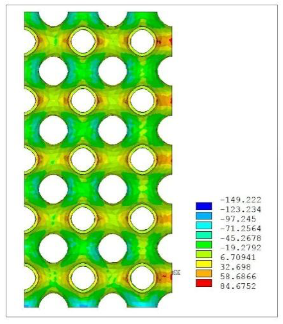
Figure 9 reports an iso-colour representation of the compressive stress distribution relative, respectively, to the radial scaffold (
Figure 9a) and the quadratic scaffold (
Figure 9b).
The stress distribution in the radial scaffold appears less homogeneous with respect to the quadratic scaffold, thus, showing a trend similar to that reported for the linear structure. As for the quadratic scaffold,
Figure 9b reports the stress obtained by applying the load in the
y direction similarly to the radial scaffold. However, considering the resultant different arrangement of the cells in the orthogonal directions, the model was also analysed under uniaxial compression by applying the load on each of the other orthogonal directions. This analysis showed a trend in stress distribution, qualitatively, similar to that obtained by applying the compression load in the
y direction.
These results together with the analysis of the geometrical configuration of the quadratic model, briefly described in the previous paragraph, led to verify a potential similarity of behaviour with a scaffold of constant porosity obtained by replicating a unit P-cell in three orthogonal directions. The analogy between the two models was confirmed by the results obtained with the FE analysis conducted on this model, similarly to the structures previously considered.
Figure 10 shows the iso-colour representation of the compressive stress distribution for the model with constant porosity.
This uniform scaffold has the same thickness as the variable scaffolds previously considered and a porosity value of 0.89.
To further investigate the scaffolds analysed, the effective elastic modulus (E
eff.), given by the ratio between the homogenised stress and the applied strain, was evaluated for each variable architecture considered in comparison with the scaffold obtained by replicating a unit P-cell. The mechanical properties of a porous structure can be determined via FEA [
25] based on Hooke’slaw, and the effective elastic modulus of a porous structure can be expressed by means of the relationship:
where F
R is the reaction force calculated by the FE solver, A is the total cross-sectional area, and e
A is the applied strain. Since the applied strain is known, the parameter can be estimated. This parameter of stiffness represents an average value for the structures with variable architectures; however, it is useful to globally evaluate them.
Figure 11 shows a diagram which summarises the results obtained.
The model indicated in the diagram as ‘linear’, corresponding to the architecture shown in
Figure 6, and that indicated as ‘radial’ (
Figure 7a) have a slightly lower stiffness with respect to the scaffold ‘quadratic’ (
Figure 7b). With regard to this last structure, the diagram reports both the valuesof the effective elastic modulus obtained by the application of a compression load, respectively, in the
x and in the
y direction. The value obtained by the application of the load in the
z direction was found to have an intermediate value between the two reported.
From the diagram it is possible to observe that the stiffness of this complex structure can take a lower or a larger value with respect to that of the scaffold with a uniform architecture, according to the direction of the loading, maintaining a relatively uniform distribution of the compression stress, as was observed in the previous analysis relative to strength. Consequently, this kind of structure could be useful in bone repairing when different stiffness is required in orthogonal directions, since this parameter can be adjusted in preferred directions.
Finally, it can be observed that the calculated values of the stiffness for the scaffolds analysed fall within the range of that of the human cortical bone which is estimated around 15 GPa with a large deviation depending on several factors; thus, these structures can potentially satisfy mechanical requirements for the applications proposed in this study.


