
Tree Infiltration Trenches in the City of Leipzig—Experiences from Four Years of Operation

 , , , and
Abstract

1. Introduction
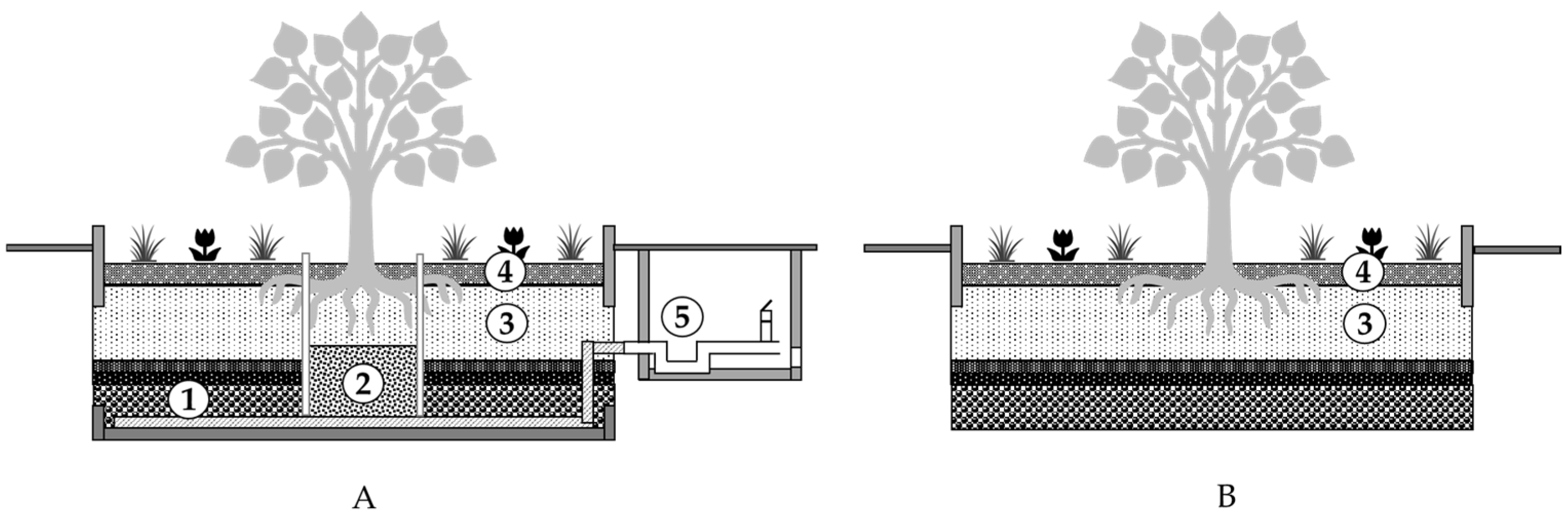
2. Structure of Tree Trenches
3. Monitoring of Diverse Functions of the Tree Trenches
3.1. Installed Sensors
3.2. Tree Vitality
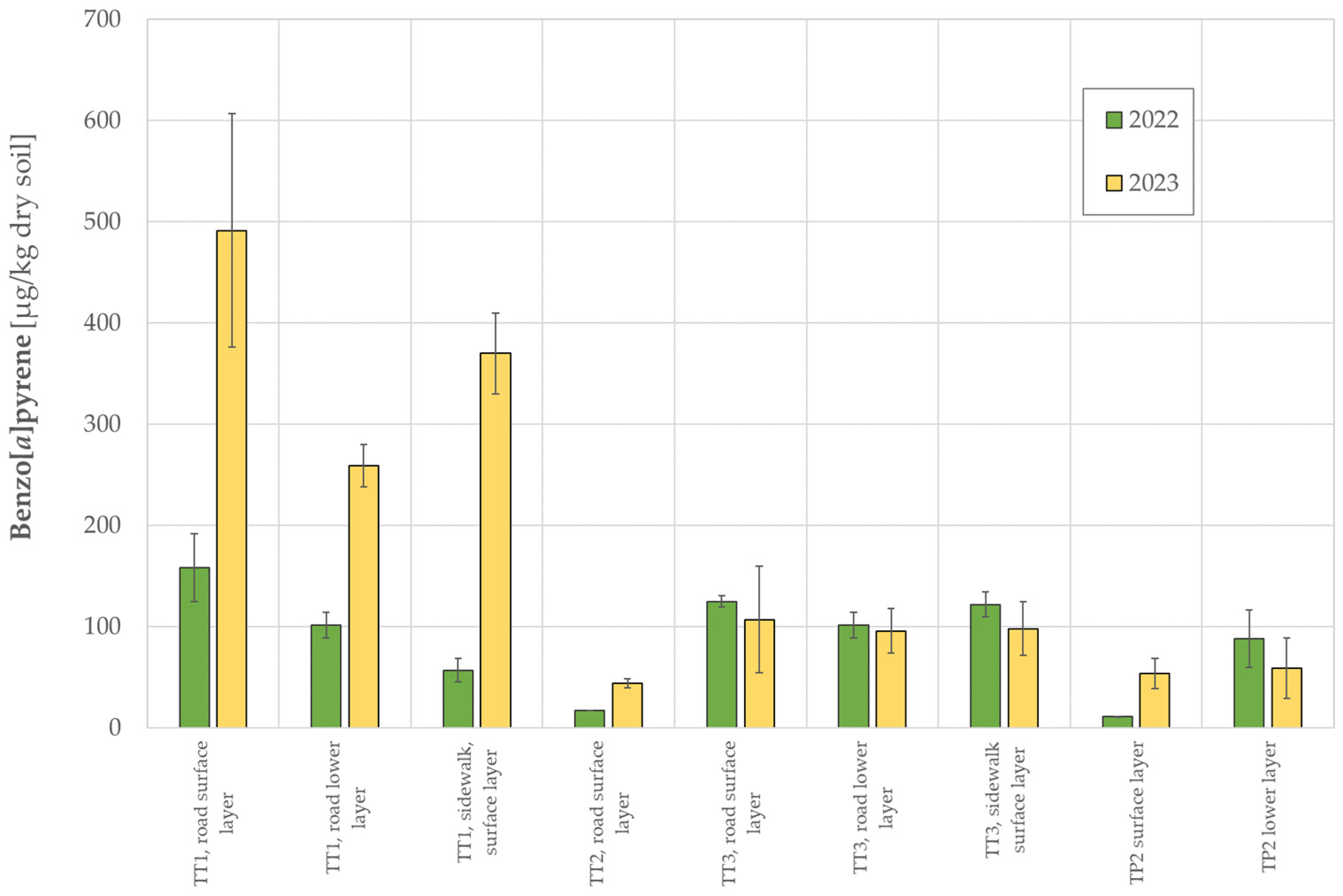
3.3. Soil Pollution
4. Lessons Learned
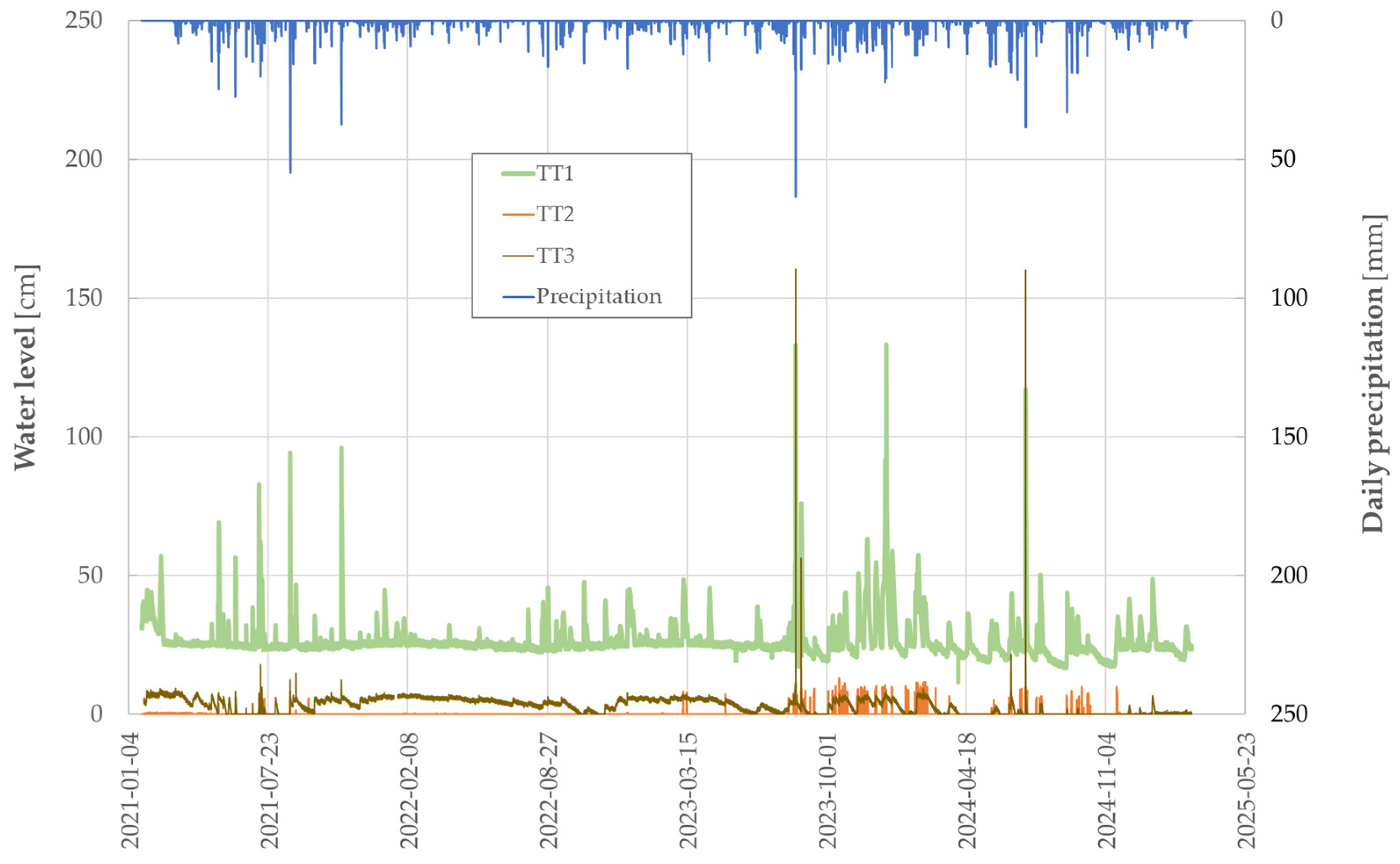
- Water inflow: The time series of the water levels in the bottom area of all three tree trenches during the entire operation time, from the beginning of the measurements until May 2025, are displayed in Figure 7. In TT1, the water level in the retention zone remained stable throughout the entire investigation period, showing peaks associated with the rainfall events. In contrast, the water level in TT3 over time indicates that the joints in the retention room were not properly sealed during construction, resulting in a reduced water-holding capacity. The water level in TT2 only shows small peaks during rainfall events, which disappear very quickly. In the case of both TT1 and TT3, water level reached heights of more than one meter during stormwater events, three times in the case of TT1 and twice for TT3 (Figure 7). This means that there was most likely overflow into the sewage system (no flow meter is installed in the overflow pipe). A rapid increase in water level was found in the period when the street side inlet holes were manually cleaned by UFZ staff using a bottle brush. The holes tend to become clogged by leaf litter and street debris so that no rainwater enters the tree trenches during smaller rainfall events. Therefore, in a future construction of such trench systems for road runoff, the problem of the water inflow into the tree trench needs to be addressed. For example, curb edges with wider interruptions (approx. 17 cm wide) are conceivable, which would allow for the free inflow of water into the infiltration trench. Problems with the inflow were also reported by Szota et al. [5]. The authors compared two types of inlet systems (lintel and pit) to divert stormwater from the curb and channel into the infiltration trenches. Initially, however, stormwater did not enter some of the trenches, particularly those with pit inlets, indicating that the inlets were restricted. To solve the problem, changes were made to the inlet design by replacing the permeable paver filters installed in the pit inlets with stainless steel mesh, and to the regular maintenance by cleaning the inlets through emptying the basket filters in all inlets every six weeks.
- 2.
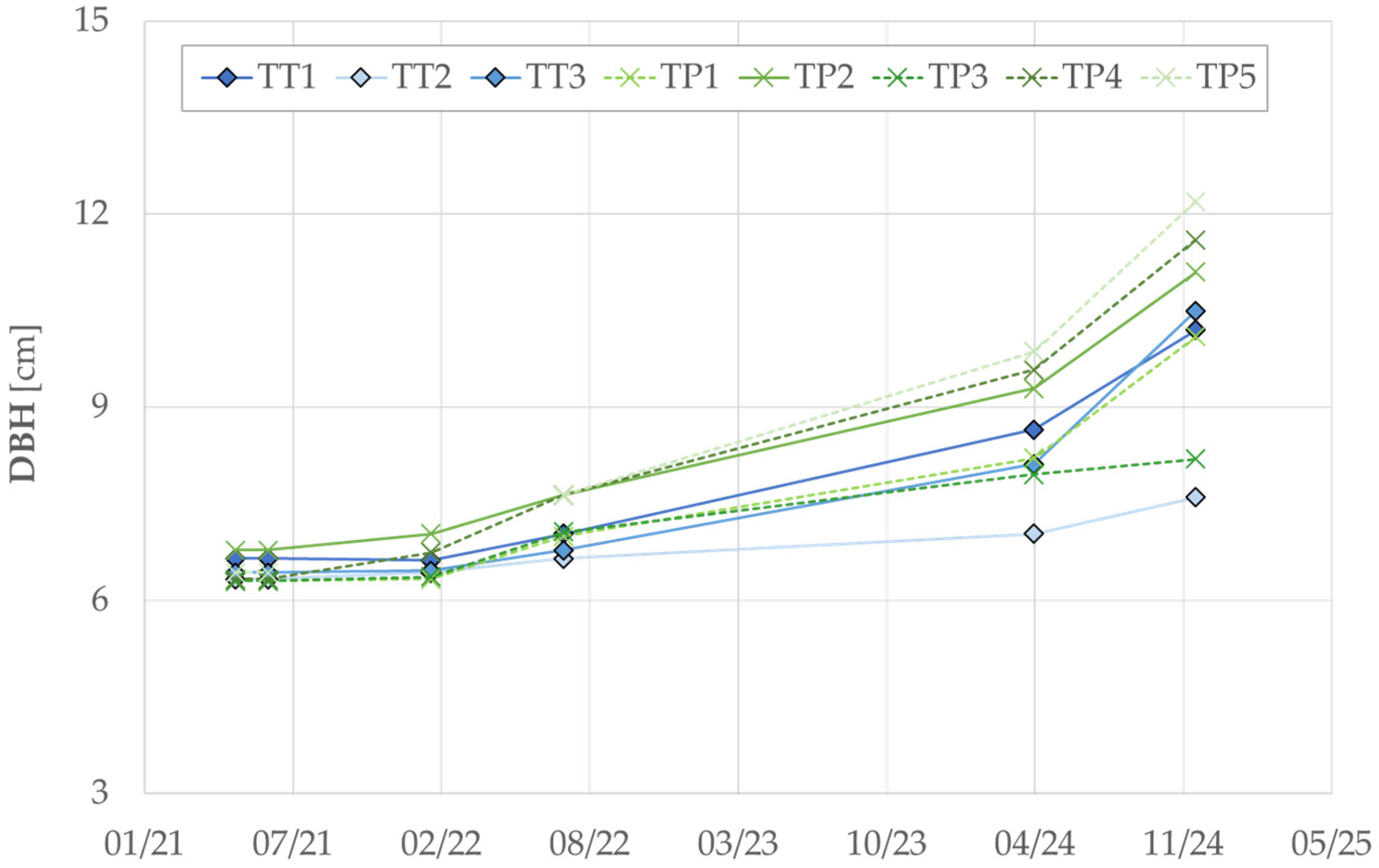
- Construction defects: In addition to the suboptimal performance of the roadside inlets to the tree trenches, design flaws were also identified during operation. In the case of TT3, the bentonite layer was apparently not tested for impermeability, resulting in a significantly reduced water retention capacity within the storage space of the tree trench. For TT2, a very slow water infiltration was observed in infiltration tests carried out in 2021, during which the tree trenches were artificially filled to the top with water and the infiltration capacity was assessed (0.58 cm/h in comparison to 9.41 cm/h in the case of TT1 and 6.14 cm/h for TT3). This situation is caused by excessive compaction during the construction of TT2. A commissioned expert opinion determined very low water permeability coefficients of 8.2 × 10⁻⁸ and 9.1 × 10⁻⁸ m/s in the lower layers of −95 cm and −110 cm, respectively. In contrast, at the position of −70 cm, a water permeability coefficient of 3.7 × 10⁻⁶ was measured, indicating easier infiltration conditions in this layer. As a result of the poor infiltration in the lower part of TT2, the water was retained in the upper layer. This is also reflected in the average values measured by the soil water content sensors: 12.8 ± 0.5% in the case of SM1 vs. 25.9 ± 0.5% for SM3 (average values were calculated for the entire estimated period). Accordingly, the tree in TT2 visibly suffered from waterlogging, as already described by Sippel et al. [11]. The stem diameter of this tree is the smallest of all the trees assessed in Kasseler Straße (Figure 5). However, this tree was not the only one with vitality problems. A tree in a common tree pit in the same street (TD4 in Figure 5), which was planted at the same time as the trees in the infiltration trenches, dried out in its fourth year and had to be replaced. Tu and al. [7] reported that the implications of limited water availability in soil pits to the trees are strongly species-dependent; in their study, Acer x freemanii was more sensitive against water stress than Plantanus x acerifolia. Vitality problems in trees are also frequently reported as a consequence of road treatment in winter (e.g., in Ordóñez-Barona et al. [15]). Kasseler Straße is a relatively quiet side street with low traffic volumes and parking spaces for cars on both sides of the road. As a result, there is no winter maintenance and therefore no use of de-icing salt, which could be detrimental to the vitality of the trees. Problems with design errors were also reported by Hanley et al. [4]: only one of three infiltration trenches receiving stormwater from a car park was functioning as designed. The authors showed that trees planted adjacent to the infiltration trenches grew larger than trees planted close to trenches without infiltration. Several issues could probably be solved through more targeted construction supervision, as classic road works (i.e., high soil compaction) are often not compatible with blue-green infrastructures.
- 3.
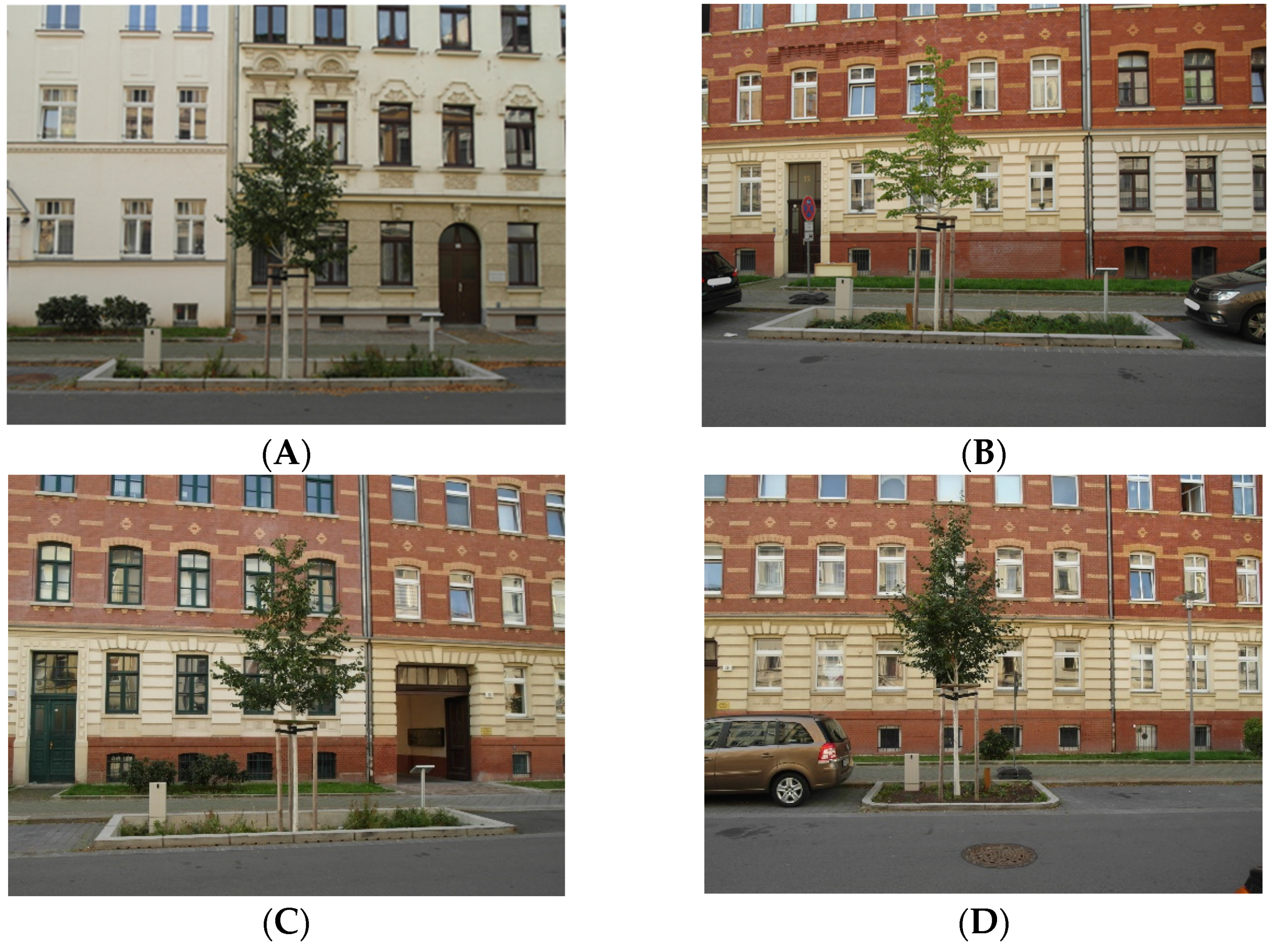
- Character of the pit: The lack of curbstones between the sidewalk and the tree trenches is criticized by residents who see the tree trenches as a potential accident site. To counter this, it would be important to adapt the groundcover vegetation planting accordingly, e.g., by using shrubs. This would also prevent the trees from being misused as bicycle racks and the trenches as rubbish dumps. The current planting using vegetation mats turned out to be suboptimal because the plants on the mats do not properly root into the depth. Another way to prevent accidents and the contamination of the infiltration trenches would be to cover them with a grate, panels, or lids, as described in Burge et al. [3].
- 4.
- Costs: As prototypes, the tree trenches in Kasseler Straße cost about 40k Euros each (without monitoring), much more than their successor models would be.
- 5.
- Communication: The first communication problems apparently occurred already during the construction. It is common practice to strongly compact all layers in the street space. In the case of TT2, however, this had detrimental consequences. Burge et al. [3] also emphasized: “Clear communication with construction contractors is important to ensure that the design intent of WSUD systems is captured in the built form.” The second challenge was to clarify the responsibility for the maintenance of the tree trenches, which are in fact a combination of a tree site and an urban water management facility. A compromise had to be found that will also be a base for future WSUD constructions. Similar experiences have been reported by others. Burge et al. [3] described bioretention tree pits, similar to TT2, where the tree is planted into bioretention filter media and the treated stormwater is then collected via perforated pipes at the base of the cell, before being discharged into stormwater pipes that also act as an overflow. The authors concluded that strong communication between constructors and designers is important to ensure that the functional intent of the WSUD system is transferred from the design to the built form. They also found that in Melbourne, the maintenance responsibilities for the tree pits lie with a number of different departments, and thus the exact responsibility for a particular maintenance task is not always clear.
5. Conclusions
Author Contributions
Funding
Data Availability Statement
Acknowledgments
Conflicts of Interest
Abbreviations
| DBH | Diameter at breast height |
| DM | Dry matter |
| n.s. | Not specified |
| PAHs | Polycyclic aromatic hydrocarbons |
| PS | Passive sampler |
| SM | Soil moisture |
| TCD | Tree crown density |
| TH | Tree height |
| TP | Tree pit |
| TT | Tree trench |
| UFZ | Helmholtz Center for Environmental Research |
| WL | Water level |
| WSUD | Water-Sensitive Urban Design |
References
- Myhre, G.; Alterskjær, K.; Stjern, C.W.; Hodnebrog, Ø.; Marelle, L.; Samset, B.H.; Sillmann, J.; Schaller, N.; Fischer, E.; Schulz, M.; et al. Frequency of extreme precipitation increases extensively with event rareness under global warming. Sci. Rep. 2019, 9, 16063. [Google Scholar] [CrossRef] [PubMed]
- Zangh, Y.; Carmin, J. Achieving urban climate adaptation in Europe and Central Asia. World Bank Policy Research Working Paper No. 5088. 1 October 2009. Available online: https://ssrn.com/abstract=1494826 (accessed on 20 November 2024).
- Burge, K.; Allison, R.; Wong, T.; Breen, P. Water sensitive urban design in the Melbourne Docklands—Raingardens and bioretention tree pits. Environment Design Guide. CAS 2008, 47, 1–12. [Google Scholar]
- Hanley, P.A.; Livesley, S.J.; Fletcher, T.D.; Grey, V.; Szota, C. Stormwater retention performance of tree integrated infiltration trenches designed for suburban streetscapes. Sci. Total Environ. 2024, 954, 176634. [Google Scholar] [CrossRef] [PubMed]
- Szota, C.; Coutts, A.M.; Thom, J.K.; Virahsawmy, H.K.; Fletcher, T.D.; Livesley, S.J. Street tree stormwater control measures can reduce runoff but may not benefit established trees. Landsc. Urban Plan. 2019, 182, 144–155. [Google Scholar] [CrossRef]
- Caplan, J.S.; Galanti, R.C.; Oshevski, S.; Eisenmann, S.W. Water relations of street trees in green infrastructure tree trench systems. Urban For. Urban Green. 2019, 41, 170–178. [Google Scholar] [CrossRef]
- Tu, M.-c.; Caplan, J.S.; Eisenmann, S.W.; Wadzuk, B.M. When Green Infrastructure Turns Grey: Plant Water Stress as a Consequence of Overdesign in a Tree Trench System. Water 2020, 12, 573. [Google Scholar] [CrossRef]
- Richter, M.; Heinemann, K.; Meiser, N.; Dickhaut, W. Trees in Sponge Cities—A Systematic Review of Trees as a Component of Blue-Green Infrastructure, Vegetation Engineering Principles, and Stormwater Management. Water 2024, 16, 655. [Google Scholar] [CrossRef]
- Leipzig Giesst. Available online: https://giessdeinviertel.codeforleipzig.de/ (accessed on 5 June 2025).
- FLL (Forschungsgesellschaft Landschaftsentwicklung Landschaftsbau e.V.). Empfehlungen für Baumpflanzungen—Teil 2: Standortvorbereitungen für Neupflanzungen. In Pflanzgruben und Wurzelraumerweiterung, Bauweisen und Substrate (Recommendations for Tree Planting—Part 2: Site Preparation for New Plantings; Planting Pits and Root Space Expansion, Construction Methods and Substrates), 2nd ed.; FLL: Bonn, Germany, 2010; ISBN 978-3-940122-22-3. [Google Scholar]
- Sippel, I.; Moeller, L.; Friesen, J. Cost-effective method for estimation of tree crown density in urban settings using a smartphone. Blue-Green Syst. 2023, 5, 121–134. [Google Scholar] [CrossRef]
- Mutzner, L.; Zhang, K.; Luthy, R.P.; Arp, H.P.H.; Spahr, S. Urban stormwater capture for water supply: Look out for persistent, mobile and toxic substances. Environ. Sci. Water Res. Technol. 2023, 9, 3094–3102. [Google Scholar] [CrossRef]
- Tedoldi, D.; Chebbo, G.; Pierlot, D.; Kovacs, Y.; Gromaire, M.-C. Impact of runoff infiltration on contaminant accumulation and transport in the soil/filter media of Sustainable Urban Drainage Systems: A literature review. Sci. Total Environ. 2016, 569–570, 904–926. [Google Scholar] [CrossRef] [PubMed]
- BBodSchV. Bundes-Bodenschutz- und Altlastenverordnung. 2021. Available online: https://www.bmuv.de/WS6809 (accessed on 30 April 2025).
- Ordóñez-Barona, C.; Sabetski, V.; Millward, A.A.; Steenberg, J. De-icing salt contamination reduces urban tree performance in structural soil cells. Environ. Pollut. 2018, 234, 562–571. [Google Scholar] [CrossRef] [PubMed]


| Parameter | Type 1 | Type 2 |
|---|---|---|
| Grain size [mm] | 0/16 | 0/32 |
| pH value [-] | 5.0–8.5 | 6.0—7.0 |
| Organic matter [mass %] | 2.1–4.2 | 1.5–2.0 |
| Total pore volume [vol %] | n.s. 1 | 45–50 |
| Maximum water capacity [vol %] | Min. 25 | Min. 25 |
| Salt content [mg/100 g DM 2] | n.s. 1 | 10–50 |
Disclaimer/Publisher’s Note: The statements, opinions and data contained in all publications are solely those of the individual author(s) and contributor(s) and not of MDPI and/or the editor(s). MDPI and/or the editor(s) disclaim responsibility for any injury to people or property resulting from any ideas, methods, instructions or products referred to in the content. |
© 2025 by the authors. Licensee MDPI, Basel, Switzerland. This article is an open access article distributed under the terms and conditions of the Creative Commons Attribution (CC BY) license (https://creativecommons.org/licenses/by/4.0/).
Share and Cite
Moeller, L.; Bernhard, K.; Kruckow, S.; Wolf, S.; Georgi, A.; Friesen, J.; Mackenzie, K.; Müller, R.A. Tree Infiltration Trenches in the City of Leipzig—Experiences from Four Years of Operation. Land 2025, 14, 1315. https://doi.org/10.3390/land14071315
Moeller L, Bernhard K, Kruckow S, Wolf S, Georgi A, Friesen J, Mackenzie K, Müller RA. Tree Infiltration Trenches in the City of Leipzig—Experiences from Four Years of Operation. Land. 2025; 14(7):1315. https://doi.org/10.3390/land14071315
Chicago/Turabian StyleMoeller, Lucie, Katy Bernhard, Sabine Kruckow, Sabine Wolf, Anett Georgi, Jan Friesen, Katrin Mackenzie, and Roland A. Müller. 2025. "Tree Infiltration Trenches in the City of Leipzig—Experiences from Four Years of Operation" Land 14, no. 7: 1315. https://doi.org/10.3390/land14071315
APA StyleMoeller, L., Bernhard, K., Kruckow, S., Wolf, S., Georgi, A., Friesen, J., Mackenzie, K., & Müller, R. A. (2025). Tree Infiltration Trenches in the City of Leipzig—Experiences from Four Years of Operation. Land, 14(7), 1315. https://doi.org/10.3390/land14071315