1. Introduction
Dewatering occurs when the degree of the saturation of a moving mass is reduced due to the high permeability of soil or terrain that the flow is propagating over. The higher the soil permeability in the propagation mass, the higher the rate of dewatering that can be achieved. It may also play an important in the dynamic behavior of landslides. The dewatering of soil reduces the fluid volume fraction in the upper part of the propagation mass. Consequently, the upper part of the propagation mass may become dry, but the lower part remains fully saturated.
Existing landslide displacement prediction models generally include physical and data-based models [
1,
2]. The data-based models have recently become popular due to providing a good relation between accuracy and simplicity. However, the physical-based models using continuum dynamics methods are still the only choice to better understand landslide propagation and predict its impacted area.
In some cases, a lahar stops because of basal friction, and its water abandons it, flowing downhill, such as in the case of the Popocatépetl volcano lahar [
3,
4]. According to the provided record [
4], on 22 January 2001, the lahar carrying the pyroclastic material triggered and melted a section of the nearby glacier and flowed down through the drainage gorges. The flow carried 160,000
of material, including
of water [
5], for approximately 14 km to the village of Santiago Xalitzintla. In this case study, the fluid abandoned the soil skeleton; consequently, the frontal part should have been dominated by the fluid phase. In contrast, the back side of the flow should have been dominated by the dynamic behavior of the solid phase.
The dewatering and desaturation of fast landslides can also be used to reduce the flows’ impact and runout distance [
6]. Structure countermeasures, such as bottom drainage screens, can be installed at the flow propagation path to mitigate the potential destructiveness of landslides. In these energy-dissipating structures, negative pore-water pressures were obtained over the surface of the permeable screens [
7] or permeable walls [
8] due to the dewatering of the flowing mass.
Currently, various continuum dynamics models [
9,
10,
11] exist in advanced simulation tools such as Dan3D [
12], RASH3D [
13], Ramms [
14], r.avaflow [
15], and Titan2D [
16] to reproduce the propagation stage of fast landslides. In these models, a few realistic simplifying assumptions are considered to obtain the approximate solutions acceptable for many engineering purposes. However, the lack of a unified approach causes several difficulties and uncertainties in an appropriate hazard assessment related to a wide class of phenomena that can occur in both saturated and unsaturated conditions. Therefore, it is essential to develop a generalized computational model to reproduce various types of landslides, taking into account different characteristics, including porosity variations, pore-water pressure evolution, soil permeability, and dewatering effects.
In landslide propagation modeling, it is assumed that, once the flowing mass is deposited, there is no separation of solid and liquid components, as in the case of mudflows. However, it has been reported that some dewatering of the flowing mass occurs following deposition [
17,
18]. Unlike previous models, this study focused on considering the principles of partially saturated soil mechanics. The crucial part is defining the phenomenon of dewatering that directly affects the dynamic behavior of a flowing mass under the process of the pore-fluid abandoning a solid structure. The developed model is also capable of reproducing the dynamic behavior of landslides propagating over a terrain equipped with structural countermeasures in which dewatering techniques are implemented.
The extended model presented in this work was implemented in the GeoFlow-SPH depth-integrated code created by an expert research team in Madrid almost two decades ago. The implemented model was developed from a one-phase finite element method [
19] to a more advanced two-phase smoothed-particle hydrodynamics-finite difference (SPH-FD) method [
20] to more properly reproduce the complex dynamics behavior of fast landslides. Several researchers [
21,
22,
23,
24] in different institutions have previously applied it to theoretical [
4], experimental [
25], and real case studies [
26].
This paper aims to present some advances in the generalized approach based on the two-phase depth-integrated model proposed by the authors to reproduce landslide propagations with a wide range of soil permeability and densities with a single set of governing equations, and to extend this concept to cases with desaturated soil. The dewatering of a flow and its corresponding change in pore-water pressure can be considered using the proposed model.
Compared with the previous propagation model, the proposed method considering dewatering has many advantages in reproducing landslide propagation with high-permeability soil or terrain. This paper provides a comprehensive review and analysis of the mechanisms and the desaturation implementation techniques.
Following this introduction, we will recall a two-phase model that simulates the fully saturated landslides. This model will be extended to a two-phase two-layer model, which is applicable for landslide cases where the phenomenon of dewatering occurs. The governing equations consist of two linear momentum balance equations, two mass balance equations and a consolidation equation. These equations are completed using a frictional rheological model, an interaction law, and an erosion law. Finally, the model will be applied to three cases where the effects of dewatering should be considered.
2. Material and Methods
2.1. Introduction
First, we need a mathematical model with a set of equations that describes the essential aspects of fast landslide propagation. The depth-integrated two-phase mathematical model, which will be recalled here, is proposed by Pastor et al. [
20,
27], where the general case of fully saturated soils is considered. It is based on the depth-integrated mathematical model of Zienkiewicz and Mróz [
28]. Depth integrated models have been used in hydraulics engineering [
29] and frequently applied to landslide propagation [
21,
30,
31,
32] due to providing a good relation between accuracy and time consumption.
The model developed by the authors is a two-phase model, similar to those of Pitman and Le [
10] and Pudasaini [
33], capable of capturing the dynamic of solid and fluid phases. The governing equation consists of two depth-integrated balance equations to describe the propagation phases and a consolidation equation to describe the evolution of excess pore-water pressure along the vertical axis in a depth-integrated model, as follows:
- (ⅰ)
Balance equations for mass and linear momentum, respectively:
where
is the excess pore-water pressure. We denote some parameters by the sub-indexes s for solid and w for fluid phases. External forces consist of basal shear stress
, gravity force
, and interaction force
. An overbar over a magnitude denotes a depth-integrated value.
is the basal slip velocity and
is an erosion coefficient. As can be seen in Equations (
1), (
2), (
3), and (
4), in two-phase models, each phase is characterized by its density
, depth-averaged flow velocity
, height
, and averaged porosity
.
is the vector of body forces.
- (ⅱ)
Consolidation equation:
which describes pore pressure evolution and consists of three terms, including (i) debris flow height variations, (ii) consolidation along vertical axis, (iii) depth-averaged porosity variations, respectively.
is a consolidation coefficient obtained by multiplying permeability
by volumetric stiffness
.
is the effective density and
is the oedometric modulus.
is the Poisson’s ratio.
This model has previously been applied to the back-analysis of a laboratory-scale flume test [
25] performed in Trondheim and several real landslide cases with different types and characteristics, including YuTung channelized debris flow [
34], Johnson landscape debris avalanche with widespread deposition [
32], Acheron rock avalanche [
35], and Sham Tseng San Tsuen debris flow [
20].
The porosity variation and dewatering have an important role in saturated soil mechanics. The general depth-integrated model described above allows the porosity to change due to the relative movement between fluid and solid phases. In some cases, a solid flowing material stops because of its high basal friction, but its pore-fluid abandons it. Another interesting example is a debris flow arriving at a permeable retention structure. If the model is applied to these cases, we will obtain a decreasing porosity that can even reach zero, as:
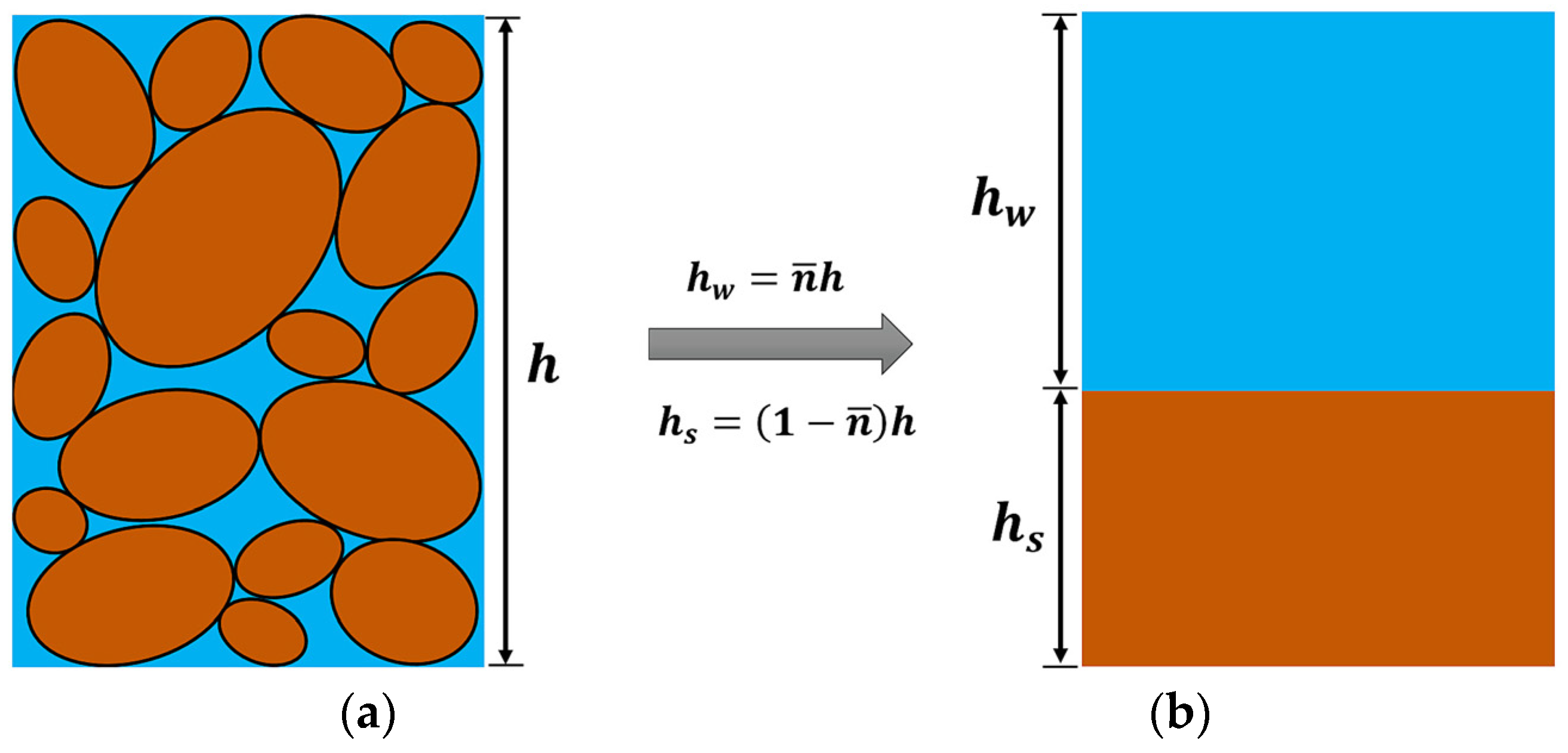
Figure 1a shows a fully saturated material consisting of granular particles and pore-water. A disadvantage of modeling landslides with the depth-averaged equation of motion is their lack of ability to define particles along the depth. To facilitate the interpretation in these models, the flowing mass was divided into a finite number of columns represented by particles, as shown in
Figure 1b. Therefore, the total height
of the mixture was divided into two partial heights corresponding to the solid
and fluid
phases, which are visualized in two different layers. However, these phases interact with each other through a drag law that depends on the variables of the porosity and permeability of the soil.
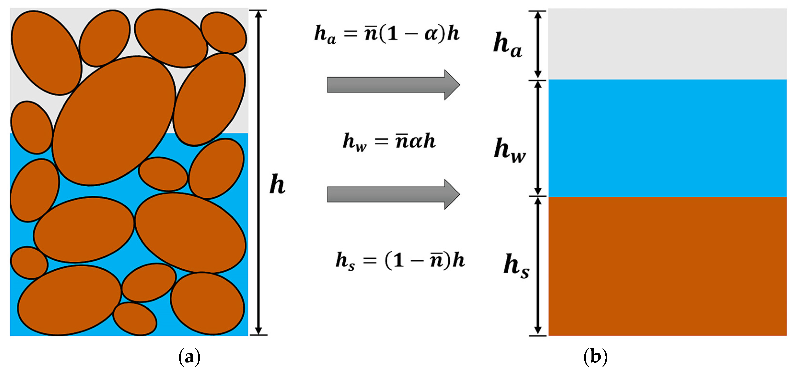
Most continuous mediums are composed of various phases. The case of partially saturated soil has three: a mixture consisting of soil grains, water, and air. Additional modifications in propagation modeling are needed to overcome problems involving unsaturated soil and to capture their dynamic behavior and mechanism, which play an important role in the propagation. Therefore, it is essential to consider another material layer for the air phase.
Figure 2a shows a crude simplification of reality, where a saturated layer exists at the bottom, where
is the relative height and
is the depth of the saturated zone, with high pore-water pressures and a top layer of unsaturated soil. In this model, a degree of saturation
is considered only for the top layer. Therefore, in this study, we considered a general case where the total height
h is divided into three layers, as shown in
Figure 2b. The partial heights of solid, fluid, and air can be obtained, respectively, as follows:
where
is the averaged porosity.
Once the porosity reaches a lower bound
(which depends on the solid grains’ size distribution), the upper part of the sliding mass will be unsaturated. During the computations, we obtained
and
from the balance of mass equations; the porosity was computed as:
If, at a certain time, it reaches the limit, we will compute the depth of the saturated layer as:
where
.
If we are given
,
,
and
, the total height can be obtained as:
2.2. Proposed Balance Equations of Mass and Linear Momentum
So far, we have described some particular cases where the soil moisture of the landslide material is lowered from a full-saturation state to a partial-saturation state during the propagation stage. This important phenomenon is called dewatering. Next, the mathematical models and numerical simulations will be developed to take into account both the saturated and unsaturated hydro-mechanical behavior of landslides. The governing equations for both the fully saturated lower layer and the partially saturated upper layer water body were solved using a depth-integrated two-phase model.
Extending the two-phase model proposed by Pastor et al. [
20] and considering Equations (
1)–(
4), the balance equations for solid and fluid phases in both fully and partially saturated soils are written, respectively, as:
- (ⅰ)
The balance of mass equations are now written as:
for the solid phase, and
for the fluid phase.
- (ⅱ)
The linear momentum equations are:
for the solid phase, and
for the fluid phase.
The above equations can be written more compactly by introducing:
The compacted balance of momentum equations is now written as:
2.3. Proposed Consolidation Equation
Pore-water pressure has a significant influence on the initiation and run-out processes. Modeling the evolution in pore-water pressure due to strong coupling between solid and fluid phases is one important part of mechanistic landslide modeling.
In the proposed propagation–consolidation model, the pore-water pressure is allowed to change in space and time from the initiation to the deposition. In this study, numerical analyses were performed in the hypothesis of fully saturated conditions using a depth-integrated two-phase model proposed by Pastor et al. [
20], which fits this hypothesis. Then, the analyses were extended to the case of partially saturated conditions caused by dewatering phenomena using the proposed model.
During dewatering, the soil becomes partially saturated, and its dynamic behavior depends on the coupling between the solid skeleton, pore-water, and pore-air. As shown in
Figure 3, a two-layer model was proposed. The hydrostatic and excess pore-water pressures were considered for the lower layer. A null pore-water pressure value was assumed at the layer above the water table. In typical cases, air consolidation times are much shorter than those of the water. Therefore, the role of pore-air pressures can be neglected.
The component of the normal stress at the vertical axis
can be expressed as the sum of the various components, as shown in
Figure 3, as follows:
where
is the hydrostatic pore pressure with zero air pressure,
is the excess pore-water pressure, and
is the effective stress.
The normal stress of layers 1 and 2 can also be obtained as:
where
are the averaged densities of layers 1 and 2:
from which, we obtain the averaged and effective density, respectively, as:
Finally, the effective stress
can be obtained as:
where
and
.
Suppose we assume that the soil is partially saturated. In that case, when taking into account Equation (
5), the excess pore-water evolution can be obtained using the following consolidation equation corresponding to the saturated layer:
The new consolidation equation is combined with the proposed balance equation, an extension of the depth-averaged model proposed by the authors, to predict the motion of a partially saturated debris flow with evolving pore-pressure distributions. The new model enhances the simulation of the dynamics of the pore-water pressure in partially saturated soils.
It is important to note that, in the proposed model, it was assumed that the landslide material consists of solid particles and a pore-water that fully saturates its pores. However, the saturated soil transit to the partially saturated soil during the propagation. In this model, the previous model proposed by the authors was extended to the case of desaturated conditions.
A reliable study of landslide propagation modeling should not ignore these relevant processes, such as pore-water pressure evolution, porosity evolution, and desaturation rate, that affect the dynamics behavior of the flowing mass. Existing models commonly do not consider all of these conditions.
2.4. Rheological and Constitutive Laws
Suitable rheological and constitutive equations must complement the governing equations presented in the previous section. The values of basal shear stress , interaction force , and erosion coefficient should be computed using these laws.
Dewatering effectively decreases the pore-water pressure in the propagation mass. As a result, the effective stress
’ is increased and the regained shear strength reduces the runout of the flow. The mechanisms of dewatering can be explained by the effective stress principle and the friction rheological law. In this study, the solid and fluid phases were modeled using the Voellmy rheological model [
36] and the Chezy–Manning formula, respectively, as follows:
where
h is the total height,
is the basal friction angle,
is the turbulence coefficient, and
is the basal excess pore-water pressure obtained using Equation (
23), taking into account that, in this rheological model, the basal shear stress depends on the basal excess pore-water pressure, and the higher the pore-water pressure, the lower the shear stress at the basal surface.
where
is the Manning’s roughness coefficient.
Two-phase models were applied in both phases: (i) a phase of water and (ii) a phase of solid. These phases interact through a drag law that depends on the porosity and soil permeability variables. There exist different drag laws, such as (i) the Darcy law for the cases with a low relative velocity, (ii) the Anderson–Jackson law [
37] for a large relative velocity, and (iii) the Kozeny–Carman law [
38,
39] for densely packed grains. Pitman and Le [
10] used the second law to model the interaction force between the two phases. The interaction force of the law is given by:
where
is the terminal velocity and
m is related to the Reynold number of the flow (1 for linear and 2 for quadratic). In a recently published paper [
40], the authors presented a new solution for the interaction terms of the balance equations, which significantly facilitates the computations of two-phase models.
Regrading the bed entrainment, there exist various empirical [
41,
42] and process-based [
43,
44] erosion laws. Pirulli and Pastor [
45] briefly described some of these erosion laws. Bed entrainment was not considered in this study. However, the interested reader can find, in the article by Pastor et al. [
46], interesting descriptions of an arbitrary Lagrangian–Eulerian (ALE) model implemented in the proposed model to consider pore-water pressure existing in the eroded materials.
2.5. Numerical Models
Concerning numerical models, meshless methods such as the material point method (MPM) [
47,
48], smooth particle hydrodynamics (SPH) [
49,
50,
51], and other mesh-free methods [
52] have been successfully applied in the area of solid mechanics. The obtained partial differential equations should be discretized and transformed to a form suitable for particle-based simulation. In the simulation model developed by Pastor et al. [
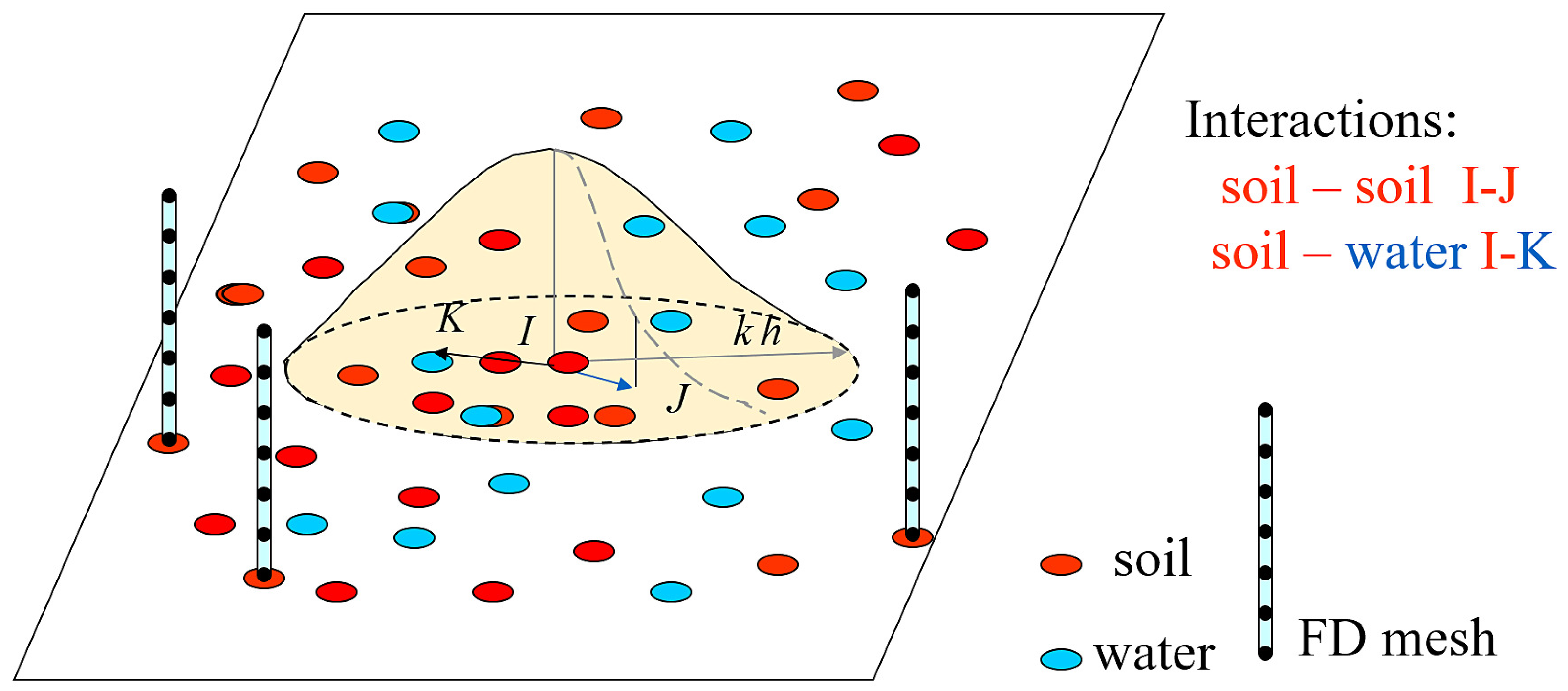
20], the balance of mass and momentum equations were discretized with the SPH numerical model, whereas the consolidation equation was discretized using a set of finite difference meshes. In this model, two sets of nodes were introduced, one to represent the solid particles’ movement and another to represent the fluid particles’ movement, as well as a 1D finite-difference mesh for describing the pore-water pressure along the vertical axis, as depicted in
Figure 4. The meshless numerical method of SPH was invented by Lucy [
53] and Gingold and Monaghan [
54] to model astrophysical problems. It has also been successfully applied in the area of landslide propagation modeling, particularly in the modeling of debris flows [
34,
55,
56] and other fast landslides [
21,
31,
32] involving large deformations. Concerning depth-integrated SPH models for landslide propagation, it is worth mentioning Pastor et al. [
9,
57,
58,
59]. Good reviews can be found in the texts of Li and Liu [
60] or Liu and Liu [
61].
The results are a set of ordinary differential equations produced in discretized form with respect to time, as follows:
- (ⅰ)
Height re-initialization:
where the subscript
a denotes the solid (s) or fluid (w) phase.
is a fictitious volume and
is a smoothing kernel function. Subscripts i and j in the above equation denote particles i and j as shown in
Figure 4.
- (ⅱ)
Linear momentum balance equation:
- (ⅲ)
Consolidation equation, suitable for the formulation of FDM:
The resulting ordinary differential equations are discretized in time with the fourth order Runge–Kutta method [
62] in the SPH and the forward time centered space (FTCS) method in the FDM. The presented model is capable of taking into account the evolution of excess pore-water pressure along the saturated layer in a depth-integrated model.
3. Case Studies
This section will apply the coupled two-phase depth-integrated model to describe flows with desaturated soil–water properties. For the sake of simplicity, numerical analyses were performed in the hypothesis of fully saturated conditions in which the saturation degree of flowing material decreases during the propagation stage.
3.1. A Dam Break Problem
One-dimensional dam break exercises provide interesting information and insights into the proposed two-phase two-layer model. In addition, these dam break exercises show the main aspects of the model in simple and controlled situations. The concept of computational models can be comprehended more quickly, showing the results of a simple dam break exercise rather than a landslide over complex terrain. In this study, dam break problems were used to demonstrate the capability of the proposed model to capture the physical aspect of dewatering in fast landslides, which has not been considered before.
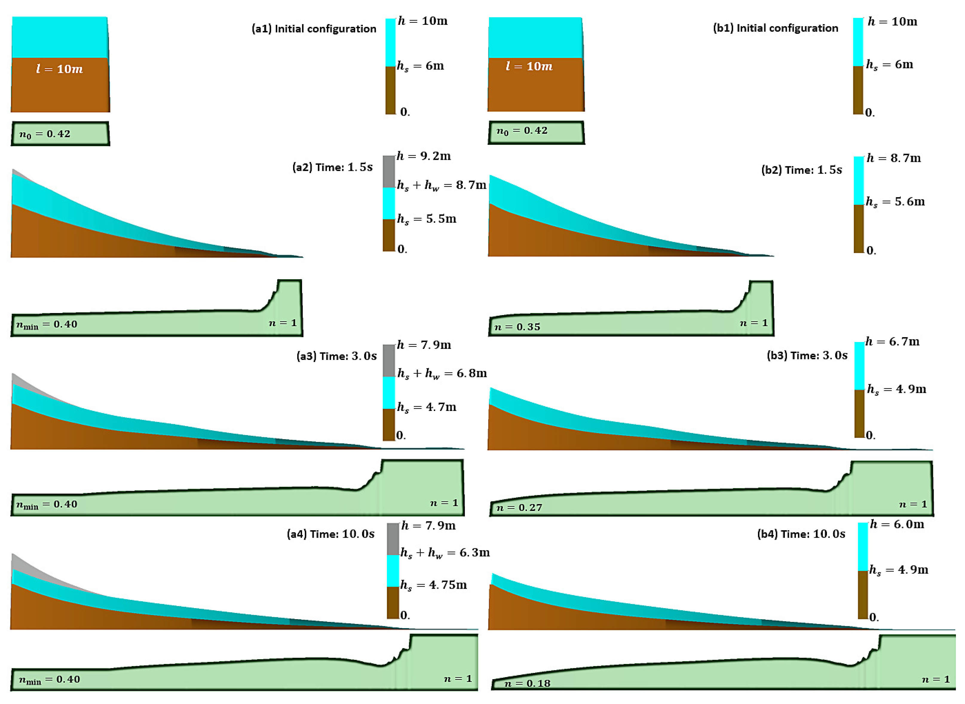
Figure 5 shows the fully saturated mixture with the partial heights of
and
for the solid and fluid phases, respectively, at the initial conditions. The mixture was assumed to be maintained between two dams, and once the dam on the left side suddenly collapses, the two-phase material flows. The minimum porosity
of the material was assumed to be 0.4. It is important to note that desaturation starts once the porosity decreases and reaches the limit. To consider a fully saturated material, the initial porosity
was assumed to be 0.42, for which, the densities of solid particles, the fluid phase, and bulk were
= 2400
,
= 1000
, and
= 1800
, respectively. The terminal velocity
was assumed to be equal to 5 m/s, corresponding to a debris flow having high-permeability soil.
Figure 5a,b show the simulations performed through the new two-phase two-layer model considering dewatering effects and the previous model [
20], respectively. The numerical results of porosity, partial height, and total height are shown at times 0, 1.5, 3, and 10 s. As shown in
Figure 5a1,b1, the initial porosity
of the flowing mass is 0.42. It increases at the frontal part of the flow and decreases at the backside during the propagating stage. Once the porosity reaches its minimum, the degree of saturation starts decreasing, and, consequently, the phenomenon of dewatering, which the previous model [
20] was not able to reproduce, occurs at a rate that depends on the soil permeability. The total height and porosity profiles exhibit a substantial evolution due to the high soil permeability and desaturation rate. As depicted in
Figure 5a4, the porosity reaches unity at the frontal part of the flow once the water leaves the solid skeleton. The solid particles cannot be mobilized at this stage due to low interaction forces between phases. Therefore, the material behavior can be described as drained due to the rapid dissipation of pore-water pressures and the short consolidation time. This saturated granular flow can be representative of wet rock avalanches or debris flows consisting of soils with a high permeability.
3.2. Flume Test
Flow velocity can be reduced using structure countermeasures. Some of these structures, such as flexible nets and bottom drainage screens, are designed to dissipate basal pore-water pressure and desaturate the flowing mass. In return, soil particles regain contact friction, so the shearing resistance of the moving mass increases.
In this simulation, the capacity of the extended model was evaluated to reproduce a debris flow on a small-scale flume test. The laboratory test was performed by Yifru [
63] at Trondheim to illustrate the effectiveness of the structural countermeasure of the bottom drainage screen. For the first time, the mentioned flume test was simulated using the 2D depth-integrated SPH-FD model. The small-scale laboratory test was performed in a 10 m long channel. It has two parts: (i) the main channel, which is 6 m long and 0.3 m wide with a
inclination, and (ii) a deposition area, 4 m long and 2.2 m wide with a
inclination.
Figure 6a shows the initial configuration of the test with fully saturated debris material with a total volume of 25 L and a solid concentration of 60%. Considering that the source material’s solid concentration is 60%, the densities of soil particles, interstitial fluid, and mixture were taken with values of 2750
, 1000
, and 2050
, respectively. The interested reader will find a detailed description of the experiments in the text by Yifru [
63].
Figure 6b shows that the debris flow is passing through the boundary wall at the main channel. As shown in
Figure 6c,d, once the flowing material crosses the bottom drainage screen, the velocity of the solid particles starts declining rapidly. At this stage, the basal total pore-water pressure dissipates during the propagation over the screen. Consequently, the excess pore-water pressure instantly becomes equal, but opposite in sign, to the hydrostatic pressure at the basal surface. Due to the low permeability of the soil, only a considerable amount of water at the basal surface abandons the solid skeleton. Therefore, the pore-water pressure still exists in the body of the flow, and the presented depth-integrated two-phase SPH-FD is capable of considering this essential physical aspect. It is important to note that the change in concentration of the debris flow due to the drainage of pore-water through the basal screen causes the soil particles to regain their contact friction. Therefore, the basal shear stress of the flowing material increases, which the presented model is capable of considering when using the Voellmy Equation (
33).
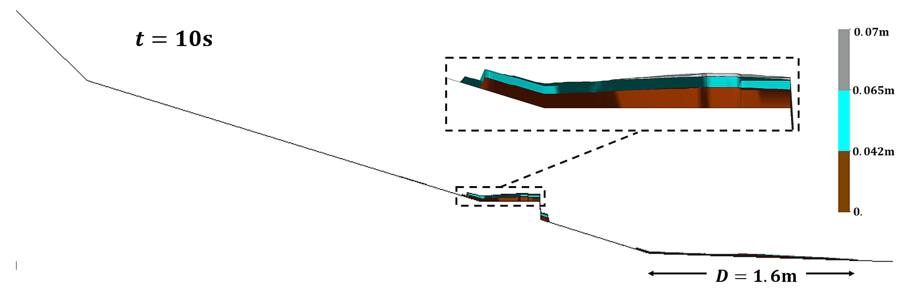
Figure 7 shows the numerical results of the final deposit thickness consisting of three layers of solid, fluid, and air at a propagation time of 10 s produced by the proposed model. As shown in the figure, there are two distinguishing parts of the debris deposit. (i) The first is the debris mass accumulated over the permeable screen with a deposit thickness of 7 cm. (ii) The second is the debris mass accumulated with a maximum height of 2 cm in the deposition area. The numerical results satisfactorily reproduce the runout distance and final deposition heights of the laboratory test over the permeable screen and the deposition area. The desaturation rate is relatively low in this case due to a high water content and low soil permeability. However, a significant amount of material trapped over the screen shows the effectiveness of this energy-dissipating structure against fast landslides.
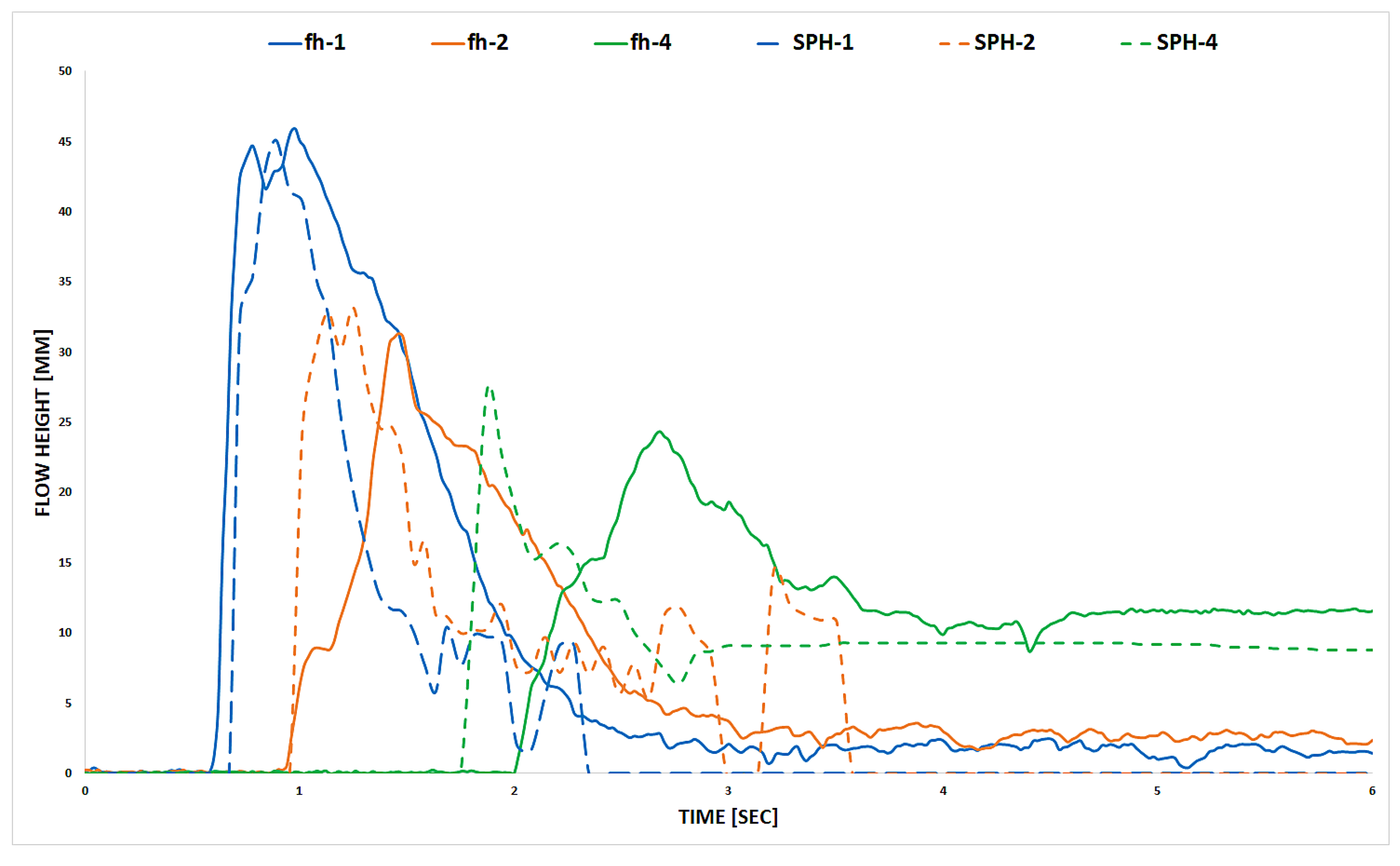
The flow heights recorded by sensors (fh-1, fh-2, and fh-4) and the computed flow heights (SPH-1, SPH-2, and SPH-4) at distances of 2.6 m, 5 m, and 5.6 m are plotted in
Figure 8. The arrival time of the flow front obtained from the presented numerical model fits with the laboratory results of the fh-1 and fh-2. The flow shows an exception at the fh-4, where the simulation looks faster than what was observed in the laboratory. This could be because of the complexities of a depth-integrated model used to reproduce a small-scale flume test equipped with boundary walls. In such cases, the velocity distribution along the channel width has a maximum at the center, and zero at the sides, which was not considered in the presented model. However, the depth-averaged flow height was able to reproduce the flow heights and deposition thicknesses of the flume test well.
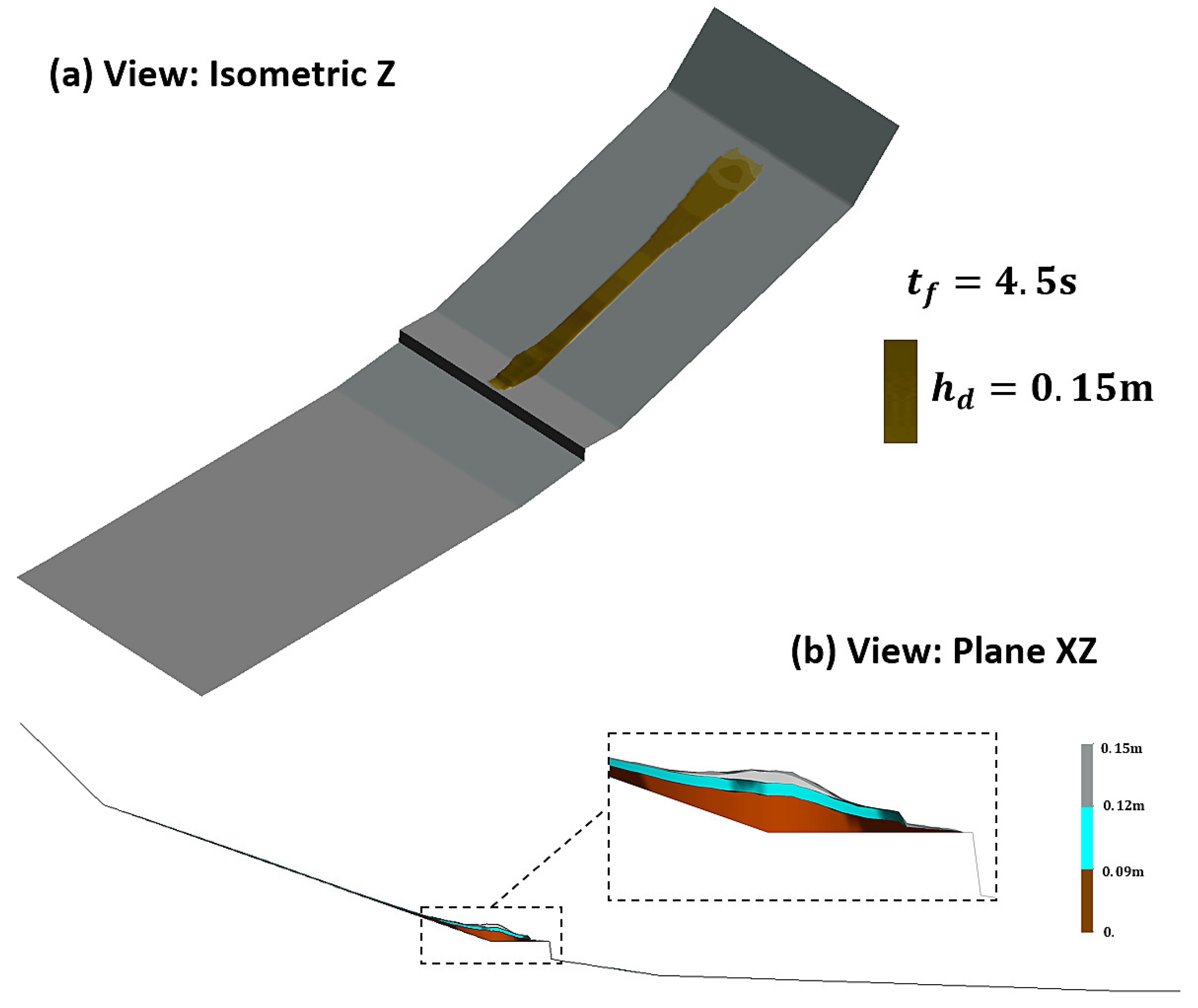
Out of curiosity, we assumed that the permeability of the soil used in the laboratory was high. Thus, we simulated it with the presented method.
Figure 9 shows the deposition shape and thickness from two perspectives obtained from the numerical model. Such a flume test containing high-permeability soil has not been physically modeled. As we expected in this scenario, almost the whole material is trapped over the screen. The reason is that, the higher the soil permeability in the propagation mass, the higher the desaturation rate that can be achieved. Consequently, the lower the pore-water pressure, the higher the shear strength at the base of the material.
The primary purposes of installing such structures are to separate some amount of water from the flowing mass, weaken the pore-water pressure, and decrease the propagating mass’s velocity. To capture the realistic behavior of solid and fluid phases and their interaction, the models must take into account pore-water pressure evolution and desaturation to simulate flow-like landslides on a terrain equipped with permeable walls or screens.
3.3. Real Case: Popocatépetl Volcano Lahar
In some cases, the phenomena of flowing mass dewatering may occur following deposition [
17,
18], such as the Popocatépetl volcano lahar in which the flowing mass stopped because of basal friction, and its water abandoned it, flowing downhill [
3,
4]. In this case, the lahar behaved as a debris flow at the initial stages of the propagation. Once the phenomenon of dewatering occurred, it behaved as a debris flood throughout its propagation up to the deposition.
Popocatépetl is an active volcano with destructive eruptive phases, located 70 km southeast of Mexico City with a population of 24 million. Hundreds of lahar events have occurred in the last two decades along the Huiloac channel. These lahars took place in 1997, 2001, and 2017 due to the earthquakes or the melting of the Ventorillo glacier, which triggered two large lahar and hundreds of shallow landslides. The volume of water in the mixture that caused the 2001 lahar flow was much greater than the volume corresponding to the 1997 and 2017 debris flows.
It has been reported [
4] that:
“On 22 January 2001 the destruction of a dome inside the crater triggered a pyroclastic flow that crossed the glacier and flowed down through the drainage gorges. The flow abraded the glacier and triggered the melting and release of of water, based on calculations from photogrammetry records of the reduction in the mass of the glacier. Four hours later a lahar was initiated in the valley head areas; this carried the pyroclastic flow materials down Huiloac Gorge for approximately to the immediate surroundings of Santiago Xalitzintla. The lahar transported 160,000 of material, including 68,000 of water [5]. This lahar behaved as a debris flow throughout its course [64]. Initial lahar volume was estimated by different methods [5,65] leading to oscillating values from to for 1997 lahar and to for 2001 lahar."
The densities of the soil particles, pore-fluid, and mixture were taken with values of
,
, and
, respectively. These values agree with the case description of the flow mass consisting of a considerate portion of water (i.e., over 68,000/160,000 = 42.5% of the flow mass is water). Entrainment was not considered in the simulation due to the observation [
4] that this lahar event had a low erosive power. Due to the high permeability of the material [
66], the terminal velocity
and oedometric modulus
were taken as
and
, respectively.
The Popocatépetl lahar was simulated by Haddad et al. [
4] using a one-phase depth-integrated SPH model. They assumed the material to be of Bingham type, its yield strength
, and viscosity
being selected as 540 Pa and 15 Pa.s, respectively. In one-phase models, the Bingham model could be a better choice than a frictional rheological model to simulate a slurry debris flood. To apply a one-phase frictional rheological model to the lahar with the watery nature, an extremely low friction angle should be adopted to reproduce the lahar’s runout distance, which does not agree with the reported observations. In the one-phase model, the results are more sensitive to the parameter of the frictional angle. On the other hand, employing more input parameters in a two-phase model allows for better matching between the simulation results and measurements. In addition, in the frictional rheological model, the basal shear stress depends on the basal pore-water pressure, and it is modified following pore-water pressure evolution at each node and time step. The higher the pore-water pressure, the lower the shear stress at the basal surface. Therefore, the apparent friction angle introduced would be much smaller than the measured one because vertical consolidation could have changed it during the propagation phase. In this simulation, the solid and fluid phases were modeled using the frictional rheological model and the Chezy–Manning formula, respectively. Concerning its rheological parameters, the basal friction angle of
, the Manning roughness coefficient of 0.015
, and no turbulence coefficient were considered.
The simulation of the Popocatétl lahar was performed using the proposed two-phase two-layer model for the entire propagation of the event. Depth-integrated numerical tools for simulating this event are ideal due to its large runout zone and debris volume.
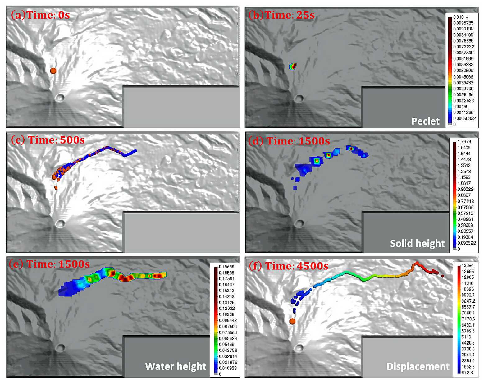
Figure 10 summarizes the simulation results and shows that the proposed model successfully simulated the lahar.
Figure 10a shows the topography and the initial condition used in the model to simulate the Popocatépetl lahars. The numerical analysis was performed using a 15 m × 15 m digital terrain model. The initial mass was schematized into two sets of 12,275 SPH computational points, one representing solid particles and the other representing fluid particles, 5 m spaced. Increasing the number of computational elements could improve numerical results, with the trade-off being an increase in computational time, particularly in this case study with a large domain area.
We present in
Figure 10b the isolines of the basal Péclet number
at time 25 s, where
. This results in
, which indicates that the consolidation time is much larger than the dewatering time.
As shown in
Figure 10c, a large volume of fluid has abandoned the solid skeleton at time 500 s.
Figure 10d,e show the propagation heights of the solid and fluid phases, respectively, at the time 1500 s, indicating that the fluid phase at the front of the flow is the dominant phase.
Figure 10f shows that the simulated lahar reaches the final deposition, and that the computed and measured run-out distance is very close to each other (14 km). Until now, no numerical simulation model has been reported that is capable of capturing the mechanisms of dewatering in an actual landslide during the propagation stage.
It is important to note that the numerical results of the developed model are more sensitive to the variables of the terminal velocity, stiffness of the mixture, and, consequently, the consolidation coefficient. Therefore, the characteristic times of propagation and consolidation are the key aspects of the proposed model.
4. Discussion
In the previous section, we performed three simulations using the proposed depth-integrated two-phase two-layer SPH-FD model. The simulation results of the flow heights, porosity profiles, basal Péclet number, and runout distance were shown at different time steps. In all of the case studies, the porosities of the mixtures evolve during the propagating stage. The degree of saturation remains equal to unity until the porosity decreases and reaches the minimum porosity of the material. After this point, desaturation starts at a rate that depends on the permeability of the soil. In these cases, a large volume of fluid abandons the solid skeleton due to the high permeability of soil or terrain. The results show that the fluid dominates the frontal part of the flowing mass with a high soil permeability whereas the solid dominates the backside. In such cases, the interaction forces between the phases are not strong enough to mobilize the solid particles. For these reasons, dewatering has been used as a means to mitigate the propagation of fast landslides. Therefore, applying the proposed model that takes into account dewatering is essential to capture the realistic behavior of solid and fluid phases and their interaction. The proposed two-layer model considering dewatering in a flowing mass can be implemented in all depth-integrated models regardless of the numerical method considered.
These numerical tools have many limitations, particularly depth-integrated models due to disregarding vertical accelerations. We can only discuss here the capabilities of these computational models in capturing some physical aspects of landslide propagation. Consequently, engineers or users must verify that these tools with many restrictions are capable of carrying out their case studies.
5. Conclusions
The purpose of this paper is to present a simple depth-integrated model that describes the propagation of fast landslides containing desaturated materials caused by the high permeability of soil or terrain. It is a two-phase model capable of discretizing a soil–water mixture in two sets of SPH nodes carrying all field variables, such as the velocity, displacement, and basal pore-water pressure. It is also a two-layer model, with an upper desaturated layer and a lower saturated layer, which enhances the description of dewatering. Pore-water pressure evolution can be described along the vertical axis in a depth-integrated model using a consolidation equation discretized by the finite difference method.
The model can be applied to two cases where the phenomenon of dewatering may occur. Dewatering can be the consequence of (i) pore-fluid leaving the solid skeleton due to the high permeability of the soil or (ii) pore-fluid draining through a structural countermeasure, such as a bottom drainage screen.
First, a one-dimensional dam break exercise was used to demonstrate the main feature of the proposed model compared to the previous model. In this exercise, the limitations of the previous model were shown. Then, the model was validated by reproducing a complex dynamic behavior of a debris flow on a flume test equipped with a bottom drainage screen by comparing the numerical results with the measurements obtained from the experiment. Finally, the model was applied to a real lahar case where the phenomena of flowing mass dewatering occurred.
These cases demonstrated that it is essential to take into account (i) the effects of desaturation by using a two-layer model and (ii) the effects of dewatering in propagation modeling by implementing the vital parameter of relative height in the governing equations. In fact, by comparing the numerical results obtained for landslide problem modeling to the experimental-measured and field-measured results, we improved the capability of previous models to simulate the desaturated soil behavior for landslide propagation analysis.
The proposed two-phase two-layer SPH-FD model is capable of correctly performing the time–space evolution of pore-water pressures while considering desaturation during the whole propagation stage over an impermeable and permeable bottom boundary. Using this model, it is possible to reproduce the effect of desaturation on the drained behavior of saturated coarse-grained soil.


 ,
, 
