1. Introduction
Significant changes in human society have led to intensive urbanization, resulting in a shift of the population from rural to urban residence. These changes have also entailed an increase in water demand and raised the need to find new solutions for water supply, due to the population growth and improvement in quality of life. The increasing water demand is also associated with climate change, which is linked with more extreme weather events such as floods on the one hand, and extended drought periods on the other. The large paved and constructed areas of new urban zones reduce the amount of rainwater that percolates into aquifers. Therefore, significant damages are caused during storms, and the rainwater that does reach the aquifer contains contaminants from roads and industrial zones.
In order to overcome these problems, the innovative approach of “Water Sensitive Cities” has been proposed. This approach can potentially lead to the recovery of significant amounts of water that would have been lost in the sea, through capturing the urban storm water and directing it into the aquifer. Moreover, the approach entails added values such as the prevention of soil degradation, the reduction of nutrient loads on receiving streams, and the creation of aesthetically pleasing green landscapes [
1].
The application of biofiltration systems for storm-water harvesting and reuse is suited for areas with rainfall during the entire year. These systems are capable of removing various contaminants, including organic compounds, nitrogen and phosphorous compounds, total suspended solids (TSS), and metals such as cadmium, copper, lead, zinc, etc. [
2,
3,
4].
However, the use of engineered biofiltration systems for harvesting and treating storm-water in Israel is complicated due to the prolonged dry climate period spanning 7–8 months of the year. If a biological filter concept is to be applied to remove predominantly organic matter and nutrients (by plant assimilation and by bacterial biodegradation), continuous wetting of the system is required to enable biomass (both plant and bacteria) survival. Therefore, a modified version of the biofilter (commonly planned for continuous storm-water harvesting as well as treatment of low-level concentrations of organics and nutrients throughout the year) should be used. The approach suggested herein is to use the same system for both storm-water harvesting/polishing during winter, and for groundwater remediation—mainly the reduction of high nitrate levels typical to many locations in the coastal aquifer of Israel during summer.
In many locations worldwide, groundwater is contaminated by nitrates, mainly due to agriculture fertilization and wastewater reuse. The concentration of nitrate in contaminated groundwater might exceed 100 mg/L [
5]. Nitrate is considered a harmful compound due to the methemoglobinemia phenomenon which harms children under the age of 3, and because nitrite (an intermediate of the denitrification process) is suspected to be a carcinogenic compound [
6]. Therefore, most health authorities have set the maximum concentration limit of nitrate in drinking water as 45 mg/L. Optimization of denitrification requires the control of several parameters. High oxygen concentration can fully suppress the denitrification process, while even a low oxygen concentration might lead to the suppression of nitrite reduction and its accumulation [
7]. The optimal temperature for the process is in the range of 15–35 °C [
8], and pH below 6.5 might cause nitrite accumulation [
9]. Nonetheless, the most significant parameter is the carbon source used as the electron donor. A low C/N ratio might lead to denitrification inhibition and nitrite accumulation, whereas a high C/N ratio might lead to organics leakage, ammonification [
10,
11], and sulfate reduction [
12,
13,
14]. Many studies have attempted to find an efficient carbon source for denitrification. These sources include dissolved carbon compounds such as sucrose, ethanol, methanol [
15], acetic acid, glucose, molasses [
16], glycerol, starch solution, lactose, and propionate [
17].
In our study, a solid carbon source was used as an electron donor source. Solid carbon sources are gradually hydrolyzed by bacteria, and the formed products (e.g., monosaccharides) participate in the process as electron donors. By using a solid carbon source, there is no need to pump liquid organic solution to the bioreactor and thus the problem of the leakage of residual organics in the process effluent is minimized. In addition, there is no total organic carbon (TOC) gradient along the denitrification biofilters since the organic matter is uniformly distributed [
18,
19]. Many solid carbon sources have been studied, including straw wheat [
20], starch polymers [
21], wood chips [
22], newspaper [
23], and cotton wool [
24]. In this research, crude cotton wool was used in biofilter columns, which served for the treatment of nitrate-contaminated solutions. In contrast to other vegetable sources, cotton contains almost pure cellulose fibers—only about 6% of the cotton fibers are ashes, proteins, waxes, hemicelluloses, lignin, and monosaccharides [
25,
26,
27]. Due to the lack of hemicelluloses and lignin, cellulases have access to the cellulose fibers, and due to the lack of proteins no formation of ammonia is expected. Cotton wool is considered as a sustainable source since it is very common in agriculture, and its cost is low.
The main problem of using cotton as a carbon source in biofilters is the tendency of the cotton to become compressed. This might lead to a reduction of hydraulic conductivity and to a deterioration of the process efficiency due to clogging and water channeling. This aspect was tested in the current study, which aimed at the design and operation of biofilters for the remediation of synthetic mixtures simulating nitrate-contaminated groundwater.
2. Materials and Methods
2.1. Experimental Biofilter
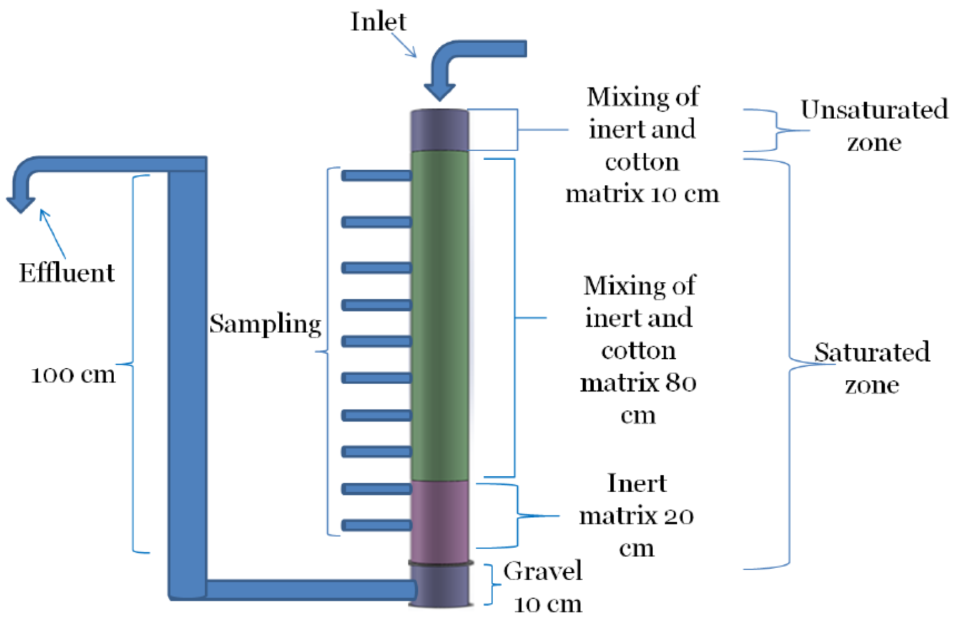
The experiments were conducted in a PVC column with a height of 120 cm and a diameter of 10 cm (see
Figure 1). An effluent pipe was connected to the base and raised 100 cm high in order to keep a water-saturated zone of 100 cm in the column. The column was installed with 10 sampling ports, at intervals of 10 cm, and its base was filled with gravel in order to provide mechanical stabilization. A siphon pipe was connected to the top of the column in order to remove the excess water, should the hydraulic conductivity deteriorate and cause lower hydraulic load than that dictated by the pump.
In a separated tank, 97 g crude cotton wool and polyethylene biomass carrier beads were mixed together at a volumetric ratio of 1:1. The biomass carriers are inert to any chemical or biological process, and they were used in order to reduce the compression effect of the overall medium. The biomass carriers’ density was 0.15 g/cm3, and their diameter was 10 mm. The mixture was mixed with 10 L sludge liquor from a nearby municipal wastewater treatment plant (WWTP).
In the 20-cm bottom layer, only the biomass carriers and sludge liquor were loaded. This layer was applied to support the polishing and removal of residual organics. On top of this, 80 cm of the mixture of cotton and biomass carriers was loaded, constituting the medium for the denitrification process. Both layers were saturated with water. On top of these two layers, a 10-cm layer of biomass carriers and cotton mixture was loaded. This layer was unsaturated and intended for oxygen consumption in order to form anaerobic conditions within the main medium. The influent was provided by a pipe connected to Masterflex L/S compact drive pump.
The influent pipe was connected to a 250 L tank filled with tap water containing 40.72 g KNO3 (to form an influent nitrate concentration of 100 mg/L). The flow rate was determined by the pump, set at 10 mL/min, which was equivalent to a hydraulic load of 0.13 cm/min in the column. Samples of 20 mL were taken from the sampling ports and from the inlet and effluent streams twice a week. Concentrations of nitrate, nitrite, TOC, sulfate, as well as hydraulic load and head loss were measured twice a week. At the end of the experiment, the column was dissembled and the cotton residue was separated from the biomass carriers and dried at 105 °C. The cotton residue was weighed every day until no weight changes were observed. Then, the cotton weight and the total TOC in effluent were subtracted from the initial cotton weight to calculate the consumed TOC mass.
In order to calculate the carbon mass consumed for the denitrification process, the cotton was assumed to contain only glucose polymer (cellulose) and the net effluent carbon mass was calculated according to the equation:
where
is the cumulative effluent carbon mass during the experiment,
is the TOC concentration in the effluent,
Q is the flow rate, and
dt is the time differential. In addition, the cotton was weighed before filling the columns and at the end of the experiment. Therefore, the net carbon mass that served for the denitrification was calculated according to the equation:
In a similar manner, the mass of the consumed nitrate was calculated by:
where
is the net consumed nitrogen mass during the experiment,
) is the nitrogen mass in the inlet, and
is the nitrogen mass in the effluent. The C/N ratio could be determined from the results of this calculation.
The experiments were conducted in two phases. In Phase I, the cotton/beads medium was compressed in the column; while in Phase II the cotton was shredded to tiny particles, mixed with the beads, and loaded gently with no compression in the column. Different activity characteristics of the biofilters were observed between the two phases, which affected process performance.
2.2. Analytical Procedures
Nitrate and sulfate concentrations were measured by Dionex LC20 ion chromatography with an AS9-SC column. Mobile phase was composed of 2 mM Na2CO3 + 0.75 mM NaHCO3 which was driven by pure nitrogen gas at a pressure of 980 psi. Flow rate was set at 1 mL/min. Nitrite concentration was measured by the azo dye colorimetric method. TOC concentration was measured by Apollo 9000 by Tekmar Dohrmann Combustion analyzer. Hydraulic load was measured by the time that it took to fill a 100 mL tube by effluent stream. The calculated flow rate was then divided by the cross-sectional area of the column. Head loss gradient was measured by a piezometric board.
3. Results and Discussion
The following results presented in
Figure 2,
Figure 3,
Figure 4,
Figure 5,
Figure 6 and
Figure 7 and by a summary
Table 1, comparing between the two phases of the experiment; where the medium was compressed (Phase I, marked A) and where the medium was mixed and loaded gently (Phase II, marked B). The meaning of the comparison between the two repetitions was to examine the compression effect of the medium and its effect on process efficiency.
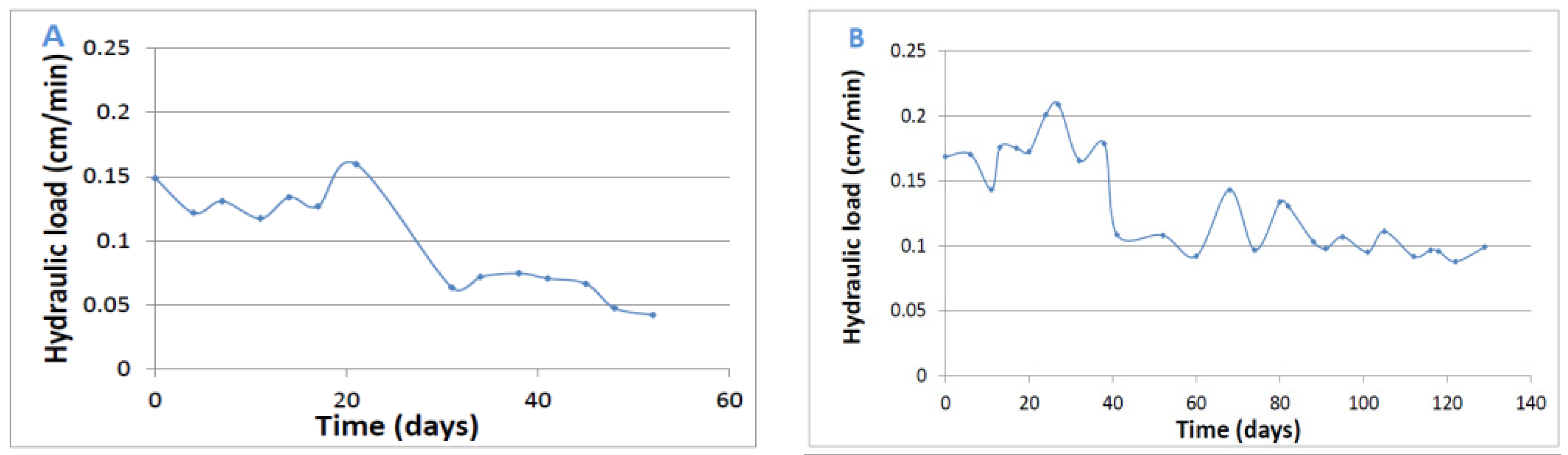
3.1. Hydraulic load
In Phase I, the hydraulic conductivity of the medium decreased due to the enhanced compression, and the hydraulic load was dictated by the conductivity and not by the pump flow rate, whereas the excess inlet flow was removed through the siphon pipe. In Phase II, the hydraulic load was almost constant during the experiment with a small decrease after 35 days due to pump malfunction. The hydraulic load in this experiment was dictated only by the pump flow rate, whereas according to Darcy’s law the hydraulic conductivity of this medium could enable higher hydraulic load.
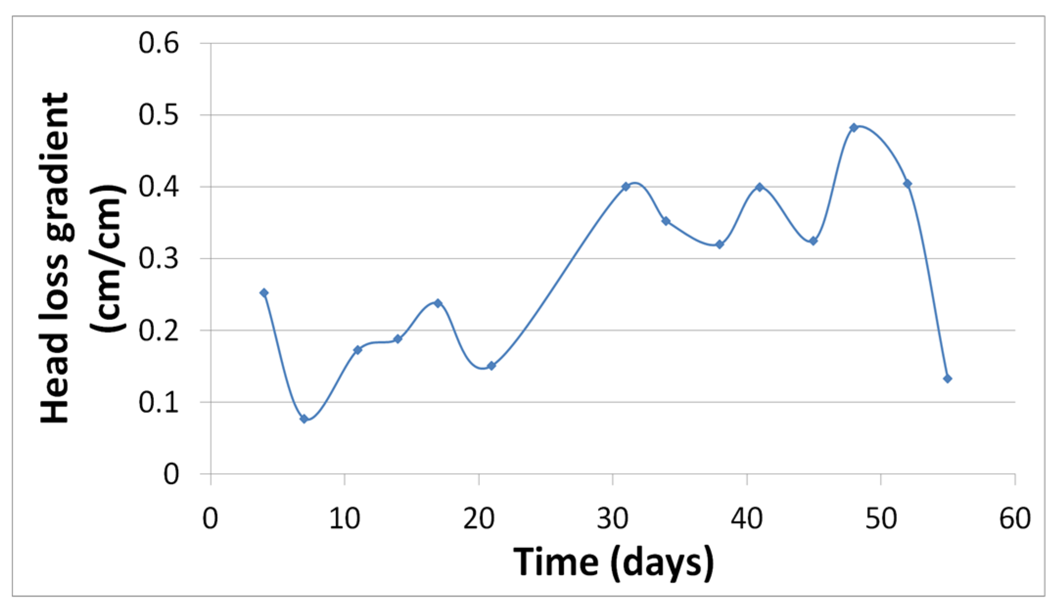
3.2. Head Loss Gradient
As shown in
Figure 3, in Phase I the head loss gradient increased with time, which means that the hydraulic load was decreased due to the decrease of hydraulic conductivity according to Darcy’s law. This did not happen in Phase II.
3.3. Nitrate Removal
As can be seen in
Figure 4, the nitrate removal was most significant in Phase I (Section A), in which the hydraulic load decrease (caused by reduced hydraulic conductivity of the compressed medium) caused complete nitrate removal (see also
Table 1). In Phase II (Section B), the gentle arrangement of the cotton/beads medium enabled a higher hydraulic load to be sustained, which limited the degree of nitrate removal. However, since the filtration media was initially mixed with 10 L sludge liquor from a nearby municipal WWTP (see
Section 2.1) in order to shorten the acclimation period, it caused fluctuations in C/Ci. We suppose that decay of biomass released excess nitrogen (mainly ammonium), which was further oxidized to nitrate and caused this phenomenon. In addition, the small variations in the hydraulic load (See
Figure 2B) can also explain these changes further on.
In many countries, a low concentration of nitrate in drinking water is acceptable. The European Commission enables nitrate concentration of up to 45 mg/L in drinking water, and therefore total removal of nitrate in the biofilter is unnecessary. In addition, total removal of the nitrate has four possible risks:
When the system becomes anaerobic, a sharp increase in effluent TOC is expected due to fermentation metabolism that consumes organic substances instead of the denitrification process. For these reasons, when designing a biofilter it is important to keep low concentrations of nitrate as accepted by the local regulations, instead of removing it entirely.
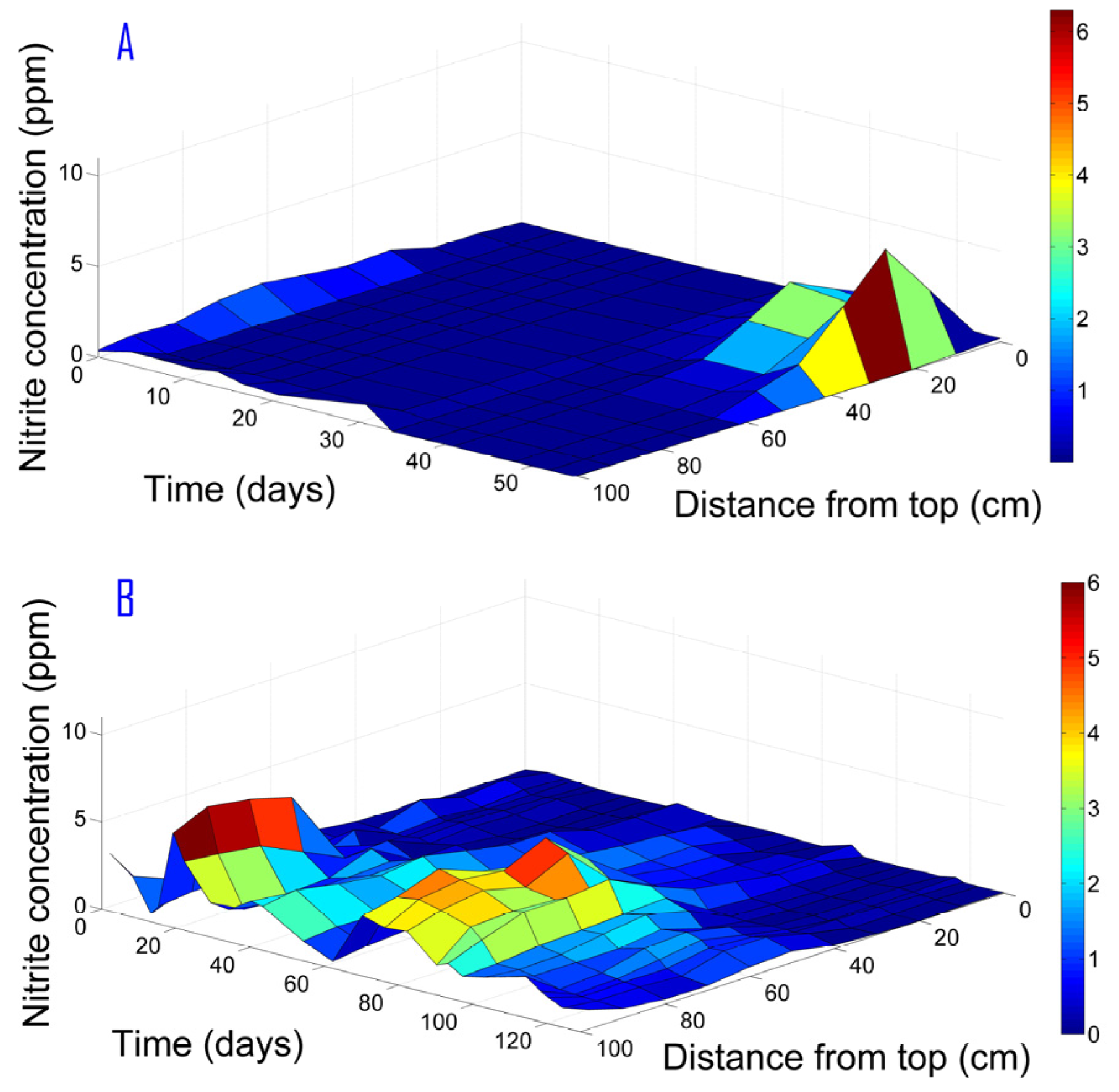
3.4. Nitrite Formation
The nitrite was formed mainly in the deeper layers of the column (approximately 40 cm from the top) as shown in
Figure 5 for Phase II. Hence, nitrite formation was not associated only with oxygen residues from the column’s top, but as an intermediate of the denitrification process. In contrast, in Phase I the maximal nitrite concentration was observed under 25 cm from the column top and was entirely consumed in the region under 60 cm from top. Since nitrite is an intermediate of nitrate reduction, it cannot be completely removed through a shorter path than that of the nitrate total reduction. A low hydraulic load will enable nitrite reduction simultaneously with nitrate total reduction as occurred in Phase I, whereas a higher hydraulic load results in nitrite convection and a wide peak in the nitrite concentration profile. Therefore, controlling the hydraulic load can assist in preventing nitrite accumulation.
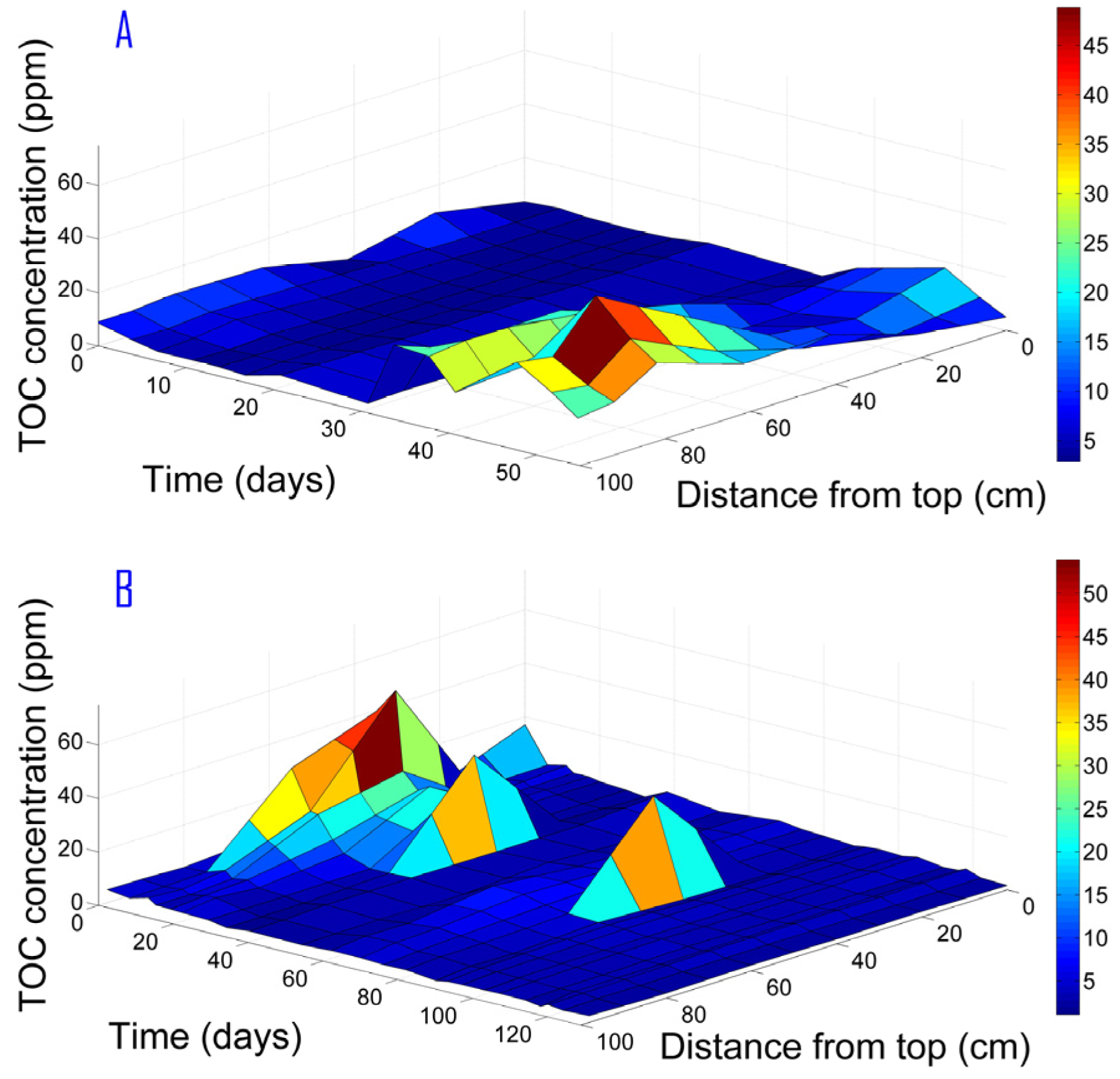
3.5. TOC Formation
In Phase I, the hydraulic load was significantly low, resulting in NOx total consumption and proliferation of anaerobic metabolism. Therefore, fermentation products appeared as a sharp increase in TOC concentration simultaneously with total NOx consumption. It can be deduced that the cotton hydrolysis is not associated only with NOx consumption due to denitrification. However, in Phase II, the TOC concentration was very low (see
Figure 6). The TOC which derived from the cotton hydrolysis was transported by the water stream. Therefore, a moderate TOC concentration increase was observed in the region under 50 cm from column top, which was oxidized in the bottom layers of the column. It seemed that the lower polishing layer was crucial to prevent TOC emissions from the column.
In Phase II, the cotton weight at the end of the experiment was 17.44 g. The carbon and nitrogen masses were calculated by integration, as detailed in the Methods section. The obtained C/N ratio was 0.88. The calculation method for the C/N ratio might be inaccurate, since it is assumed that all of the nitrate and TOC compounds were used for denitrification and/or for assimilation. Secondly, it is assumed that the C/N ratio is steady, whereas the ratio might change over time. Thirdly, it is possible that the cotton was not properly separated from the particles, which caused measurement bias. Despite these problems, this is the only method for C/N estimation since TOC derived from the cotton hydrolysis was consumed inside the column. It is not possible to assess from TOC measurement how much carbon was consumed and how much carbon was derived from the cotton. The obtained ratio is significantly lower than the theoretical ratio for the full denitrification process (1.25), but higher than the theoretical ratio for full reduction of nitrate to nitrite only (which is 0.5). These results explain the nitrite accumulation. There was a sufficient amount of organic matter for nitrate reduction to nitrite, but not enough for nitrite reduction to N2.
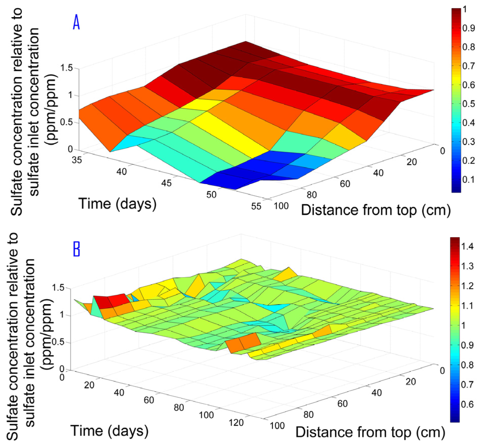
3.6. Sulfate Removal
In both experiments, the initial conditions were anoxic (NOx present), but could become anaerobic after complete NOx removal. Under anaerobic conditions, sulfate-reducing bacteria (SRB) consume sulfate as the final electron acceptor, and the metabolic product is sulfide. Sulfate measurement was performed in order to control the anoxic conditions. As can be seen in
Figure 7, sulfide production occurred only when NOx were entirely removed. As long as NOx are present in the system, even at very low levels, no sulfate reduction can occur. As found by Achtnich et al. [
12], sulfate reduction does not occur simultaneously with denitrification since the latter inhibits SRB growth. As shown in
Figure 7 for Phase I, the sulfate reduction began after about 60 cm from the top where the NOx was completely consumed, while no sulfate was consumed in Phase II.
As can be observed in
Figure 7, C/Ci for Phase II sometimes exceeded the value of 1. For this phase, sulfate actually remained unchanged (due to anoxic conditions as explained above—see also
Table 1). These irregular cases can be attributed to changes of tap water sulfate content. The source of water in our lab is a local aquifer. However, frequent mixing of groundwater with desalinated water causes changes in ion composition.
Table 1 summarizes average values and standard deviations of biofilter inlet and outlet values of nitrogen oxides, TOC, and sulfate during the two experimental phases of this study.
A mathematical model was developed in order to better understand the transformations of organic carbon and nitrogen oxides during the two experimental phases. It is based on traditional Michaelis–Menten enzyme kinetics used in modeling of bioreactors for wastewater treatment. Since modeling of solid carbon use in biofilters has not yet been done, we assumed a hydrolysis of the cotton to a simple glucose molecule, which can be utilized by denitrification bacteria for nitrate and nitrite reduction. This soluble product can also be used by SRBs for sulfate reduction, once nitrate and nitrite are eliminated (Phase I). The model was calibrated based on a batch experiment, using non-linear curve fitting in least square sense (Matlab Isqcurvefit) to obtain kinetic constants. The results are not shown herein. It was found that the cotton hydrolysis is best described by a zero-order kinetics, and therefore proceeds even with very low nitrate and nitrite concentrations. Once nitrate and nitrite reach very low values, the rate of their reduction together with dissolved carbon utilization becomes very slow. On the other hand, continuous hydrolysis causes TOC accumulation as evidenced in Phase I. Under high hydraulic load when nitrate levels and the C/N ratio are kept relatively high, TOC consumption rate for denitrification exceeds the rate of TOC release by cotton hydrolysis. This prevents TOC accumulation as evidenced in Phase II.
4. Summary and Conclusions
This research demonstrated that crude cotton wool could serve as an efficient carbon source for the denitrification process in biofilters treating nitrate-contaminated water. Due to a slow hydrolysis rate of the cotton into simple saccharine, low levels of TOC and nitrite can be kept in the treated water.
By adding an inert solid medium such as the polyethylene biomass carriers (which have lower density than water), cotton compression can be avoided or significantly decreased.
It is essential that nitrate not be completely removed from the system in order to prevent sulfide formation and TOC leaching, and to extend the biofilter’s operation period.
The major problem of a denitrification-based system is nitrite formation. Under continuous flow along a biofilter, the peak front of nitrite concentration will always appear after or simultaneously with nitrate peak front. In order to reduce the nitrite emission, it is suggested to establish a recycle stream of effluent to the influent stream. This stream will dilute inlet nitrate concentration and enable improved removal of nitrite.
In solid carbon source-based systems, the main parameter that enables system control is the hydraulic load. Therefore, by controlling this parameter, the C/N ratio as well as nitrate and nitrite removal can be optimized. The hydraulic load should not be too low in order to avoid the development of anaerobic conditions.


