Article

Thermal and Physical Investigations into Lake Deepening Processes on Spillway Lake, Ngozumpa Glacier, Nepal

by
Ulyana Nadia Horodyskyj
Science in the Wild, 40 S 35th St. Boulder, CO 80305, USA
Water 2017, 9(5), 362; https://doi.org/10.3390/w9050362
Submission received: 15 March 2017 / Revised: 1 May 2017 / Accepted: 15 May 2017 / Published: 22 May 2017
(This article belongs to the Special Issue Global Warming Impacts on Mountain Glaciers and Communities)

Abstract

:
This paper investigates physical processes in the four sub-basins of Ngozumpa glacier’s terminal Spillway Lake for the period 2012–2014 in order to characterize lake deepening and mass transfer processes. Quantifying the growth and deepening of this terminal lake is important given its close vicinity to Sherpa villages down-valley. To this end, the following are examined: annual, daily and hourly temperature variations in the water column, vertical turbidity variations and water level changes and map lake floor sediment properties and lake floor structure using open water side-scan sonar transects. Roughness and hardness maps from sonar returns reveal lake floor substrates ranging from mud, to rocky debris and, in places, bare ice. Heat conduction equations using annual lake bottom temperatures and sediment properties are used to calculate bottom ice melt rates (lake floor deepening) for 0.01 to 1-m debris thicknesses. In areas of rapid deepening, where low mean bottom temperatures prevail, thin debris cover or bare ice is present. This finding is consistent with previously reported localized regions of lake deepening and is useful in predicting future deepening.

1. Introduction

Since the 1950s, many debris-covered glaciers in the Nepalese Himalaya have developed large terminal moraine-dammed supraglacial lakes [1], which grow through expansion and deepening on the surface of a glacier [2,3,4]. As temperatures continue to rise [5] and lakes continue to grow in area and volume, they pose a flooding risk to the Sherpa villages down-valley [6,7]. Two conditions suggested to promote the formation of supraglacial lakes are sloped surfaces <2° [8] and surface velocities <10 m/yr [9]. Hence, they occur in terminal “dead ice” zones.
The Tsho Rolpa on northwest-flowing Trakarding glacier (Rowaling valley) and Tsho Imja on the west-flowing Imja-Lhotse Shar glacier (Khumbu valley) are two examples of moraine-dammed supraglacial lakes that have grown considerably in area and volume from 1950 to the present-day [10,11,12,13,14]. While there appears to be no immediate danger of lake drainage at Imja, continued monitoring is crucial to ensure the terminal ice dam, currently 500 m across, does not narrow and cause a catastrophic flood [15]. Field efforts in 2016 by the Nepalese Army have already lowered the level of the lake by 3 m in order to preemptively mitigate some of the hazard. The Tsho Rolpa differs in that its terminal ice dam already is much narrower and steeper [7]. In the event of ice collapse at the calving front, seiche waves could overtop the moraine and promote dam failure. In the late 1990s, a dam and spillway were constructed to lower the lake level and reduce the risk of a catastrophic drainage downstream [16]. Both lakes have large fetches of multiple kilometers and active calving fronts. Other than partially-ice-cored moraines at their termini, rocky (possibly ice-cored) lateral moraines bound them.
The Spillway is a base-level supraglacial lake on the south/southeast-flowing Ngozumpa glacier in the Gokyo valley, between the Rowaling and Khumbu valleys, whose growth stages have been documented since the early 2000s [4,17,18]. Spillway has the capacity to grow into a much larger moraine-dammed lake (5–6 km in length) similar to those on the Trakarding and Imja-Lhotse Shar glaciers (Figure 1), though it could become much larger in area and volume than Tsho Rolpa and Tsho Imja given the stagnation of the lower 6.5 km of Ngozumpa glacier [4,9,18]. Presently, the Spillway consists of multiple sub-basins that are gradually merging into a larger lake. Over the past three decades, Spillway has undergone cycles of rapid growth “spurts” alternating with periods of slower expansion [16]. Deepening rates vary locally in the sub-basins from less than a meter per year to tens of meters per year [4,18]. Quantifying lake expansion and deepening remains an important objective, given the millions of cubic meters of water that can potentially outburst downstream, affecting Sherpa villages. Towards this end, trainings of Sherpas via a “Sherpa-Scientist Initiative” (SSI) were carried out during the course of this field research, to ensure local knowledge of the hazards, as well as ways to counteract and mitigate hazards should they arise in the future. As of June 2016, one weather station remains at the terminus of the Ngozumpa glacier, collecting meteorological data, and one pressure transducer remains in the Spillway Lake, collecting water level data. The data are periodically downloaded by SSI-trained locals. Maintaining a research presence on the glacier is of importance as the Spillway Lake continues to expand and deepen.
While research has quantified rates of lake expansion [4], it is important also to understand processes controlling the deepening rates of Spillway Lake. This paper investigates lake floor deepening in four sub-basins of Spillway Lake using measured seasonal bottom water temperatures and numerical modeling of variable thicknesses of debris cover (0.01 to 1 m) to predict lake bottom ice melt rates. The thickness of debris remains difficult to validate in the field, due to its spatial heterogeneity as seen at the surface of Ngozumpa glacier [19]. However, numerically-modeled melt rates using temperature field data and calculated thermal conductivities provide a framework with which to evaluate previous depth changes in Spillway Lake.
Vertical water temperature and turbidity (suspended sediment concentration) measurements, lake bottom temperatures, lake floor sediment properties and open water side-scan sonar transects are presented to quantify rates of ice melt beneath debris (sediment) layers on lake floors through heat conduction, as well as to investigate lake floor structure. The results are used to identify areas that may pose the risk of rapid deepening and potential loss of stored glacial water in the future.

2. Site Description

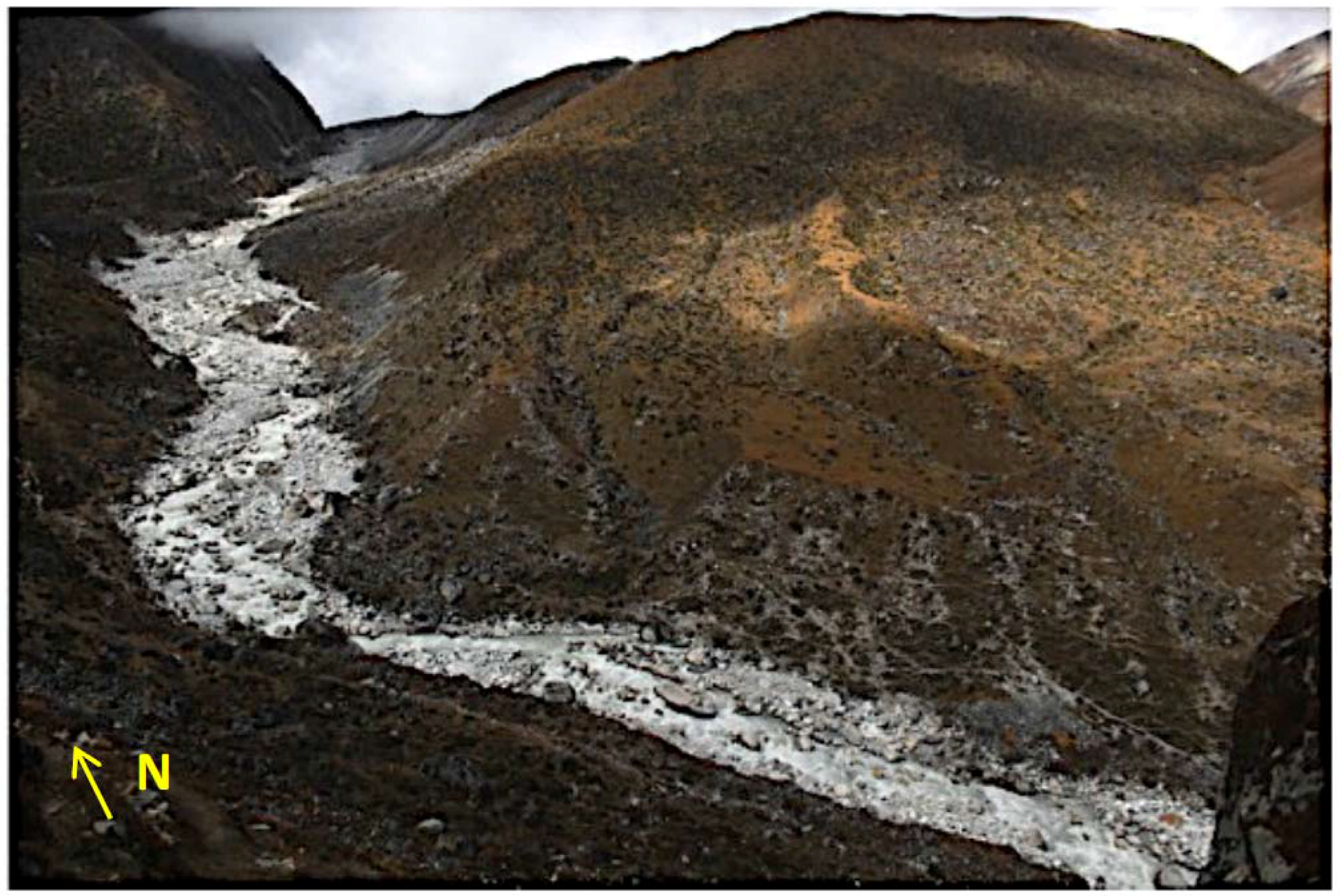
Ngozumpa is one of Nepal’s largest and longest glaciers. It flows 18 km south-southeast from the flanks of Cho Oyu (8188-m) and Gyachang Kang (7922-m) [17]. Near its terminus, at 4800-m, a large supraglacial lake has been growing in area and volume since the 1980s [4]. Its water level is controlled by the elevation of a spillway along the western lateral-frontal moraine, as seen in Figure 2.
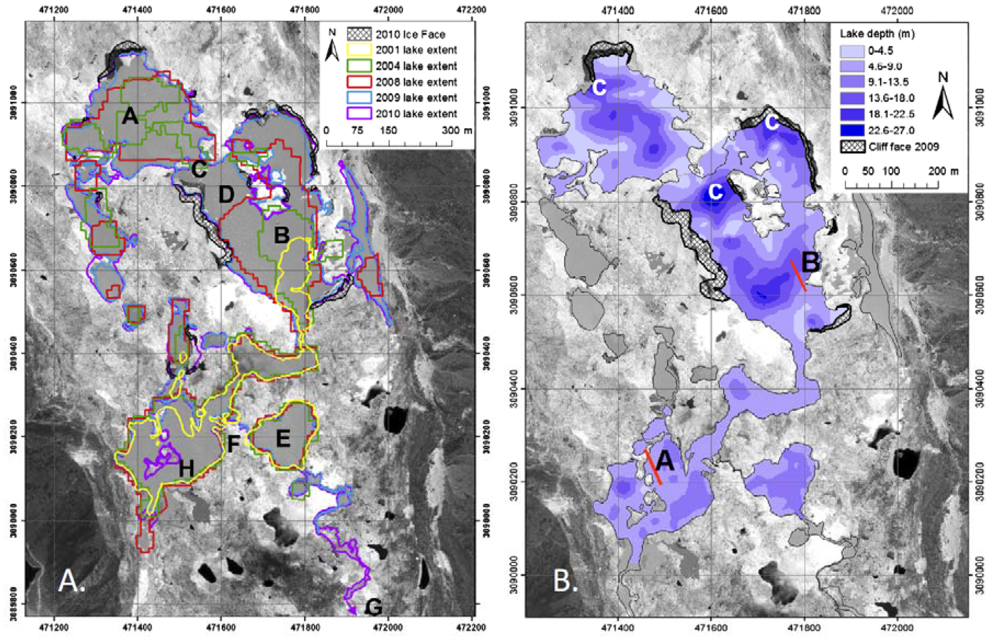
Since 2010, the development of a new connection between Spillway Lake and a stable pond called ‘Blue Lake’ (Figure 3 (feature labeled E)) may reroute water towards the eastern moraine [4], allowing for more rapid lake expansion, as well as a narrowing of the moraine dam. In 2009, an average lake depth of 10 m was found, with a 26-m maximum depth in the north and a stable region in the south (Figure 3 (feature labeled H)), and a mean depth of 14 m [4]. Spillway mean depth is shallower by an order of magnitude when comparing with the Tsho Rolpa and Imja supraglacial lakes [10,20].
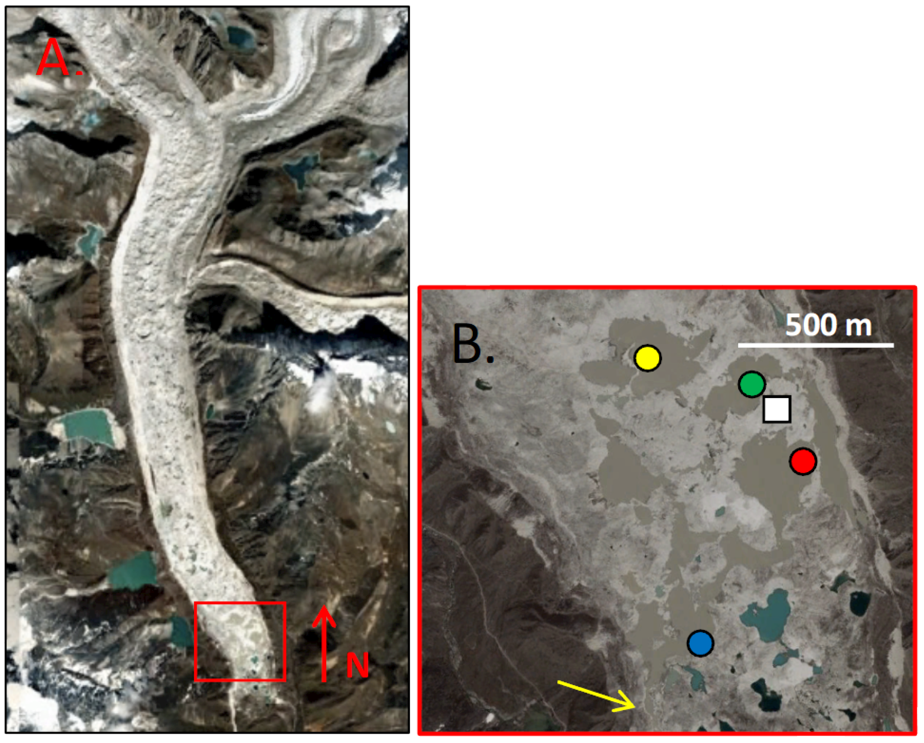
Rather than one large lake, Spillway consists of multiple sub-basins separated by debris islands and surrounded by calving and melting ice walls. The sub-basins are named Northwest (NW), Northeast (NE), Main (MB, for “Main Basin”) and Southwest (SW), with the north-south fetch of the largest (MB) measuring at ~300 m (Figure 4). Comparatively, Tsho Rolpa and Imja have over 1-km fetches, active calving fronts and bounds in the form of rocky, ice-cored lateral moraines [10]. On Spillway, exposed ice walls facing south (near NW sub-basin), north (near NE and Main sub-basins), and east (located between NW and Main sub-basins) contribute subaerial meltwater to the lake, keeping lake conditions cool during the melting (monsoon) season, despite higher air temperatures. The south-facing walls surrounding the NW sub-basin are prone to back-wasting (given their <30° slopes) and coverage by thin debris. This led to a temporary stall in the northward expansion of the lake in recent years [18].

3. Field Methods

Four study regions were selected within the Northwest (NW), Northeast (NE), Main (MB) and Southwest (SW) sub-basins of Spillway Lake (Figure 4) based on area and depth maps, as seen in [4]. The NW location was used to represent a shallowing region; NE and Main to represent deepening areas, with the latter further removed from ice walls; and SW to represent a stable/slight shallowing region. The evolution of Spillway Lake’s sub-basins since 2001 reveals that in the NW sub-basin, growth begins in 2004 and expansion continues northward from 2008–2010. In the vicinity of the NE sub-basin buoy, expansion began in 2008 and continued through 2010. At the Main sub-basin, expansion began in 2001. In the vicinity of the SW sub-basin buoy, the region has seen limited growth since its inception in 2001. ‘Blue Lake’ (Figure 3 (feature labeled E), a shallow, but optically-deep lake, has remained relatively stable, with some shoreline degradation during this time period. Starting in 2009, the development of a new channel routed some of its flow towards the south/southeast.

3.1. Temperature and Water Level Buoys

For a week in June 2014, instantaneous vertical temperature profiles were measured using a weighted cable and handheld Oakton PC10 probe with a resolution of 0.1 °C and accuracy of ±0.5 °C. For long-term measurements (June 2013–June 2014), four buoys with three sensors on each line were constructed using surface and sub-surface pool floats, anchored to the lake floor with sandbags containing debris (mud and rock) dredged from the bottom. Depth was varied, in order to capture diversity within the sub-basins. Onset temperature sensors (resolution 0.1 °C, accuracy ±0.2 °C) were tied off on the Spectra fishing cord at the surface, middle and bottom for each location. Given fluctuating water levels due to precipitation, ice melt and inputs from englacial channels, it was difficult to place sensors precisely at the surface. As water level rose, buoys would go underwater during the monsoon season; and as lake levels dropped, the risk of exposure of the sensor to the air and solar radiation was higher. Thus, “surface” here is taken to represent 10 cm below the waterline. Given Secchi disk measurements of a 15–18-cm optical depth (and solar radiation penetration depth of twice this [21]), this seemed a reasonable compromise. Onset water depth loggers (pressure transducers) were placed at the bottom of the NW and SW sub-basins, to track water level changes.

3.2. Time-Lapse Imagery and Meteorological Data

Commercially available time-lapse cameras were placed around the perimeter of Spillway Lake, in order to capture lake changes in real time. They were programmed to record a photo every hour for the duration of the monsoon from June–September 2013. During the winter months, with anticipated cold temperatures, they were reset to shoot every four hours. In April 2014, they were reset to record every hour, in order to capture spring thaw events. An Onset weather station was set up at the high point of a debris island, as seen in Figure 4. It measured air temperatures (0.02 °C resolution), precipitation (0.2 mm resolution), wind speed (±1.1 m/s), wind direction (±5°) and solar radiation (±5%).

3.3. Turbidity and Water Properties

Turbidity with depth was measured in situ (June 2014) with a handheld turbidimeter, using a 90-degree scatter nephelometer on a 30-m weighted cable. The detected light intensity is directly proportional to the turbidity of the water. Water samples were collected and measured in the lab with units reported in nephelometric turbidity units (NTU). They were then filtered, weighed and converted to suspended sediment concentration (SSC), as per the method in [10]. Other water properties, such as pH (±0.01) and conductivity (±1%), were measured with a handheld Oakton PC10 model. A black and white Secchi disk was used to determine optical depth, where an average of three measurements was taken on clear days, with the Sun overhead. Water chemistry was measured using an ICP-OES (major elements) and ICP-MS (trace elements) at the University of Colorado Boulder.

3.4. Sediment Properties

Samples were collected from lake floors using an Ekman dredge with a trigger release messenger. In some regions, lake floor materials consisted of a thick mud packet, while in others, it included a mixture of rocks, pebbles and mud. Care was taken not to sample along shorelines where large rocks could damage the dredge. Samples were measured at the Colorado School of Mines using a KD-2 instrument to quantify heat capacity, thermal diffusivity and thermal conductivity, while particle density and porosity were measured separately. An Onset temperature sensor was buried in sandbags during the 2014 monsoon season, to compare bottom debris temperatures with bottom water temperatures.

3.5. Lake Floor Structure

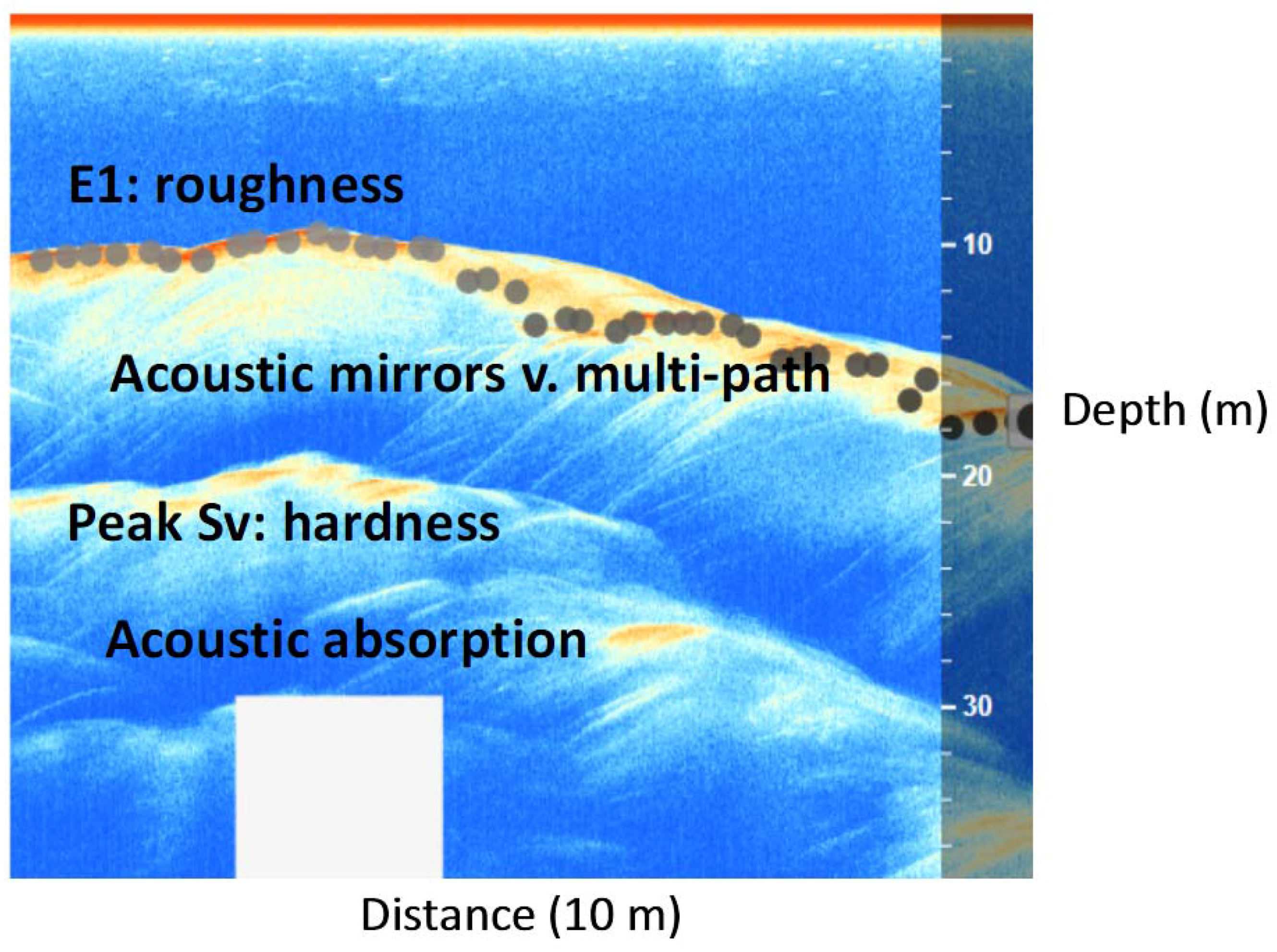
Open water side-scan sonar transects were collected in early June 2014, after the lake thaw and before the start of the monsoon. A remote-operated vehicle (ROV), developed by a team at the Milwaukee School of Engineering and Midwest ROV LLC, provided the platform for a commercial fish finder, transducer and GPS. The depths are not directly comparable with those reported in [4], who derived point-interpolated maps during the winter when the lake was frozen. Rather, these bathymetric results, with shorelines generated from collected ground waypoints (June 2014) and GeoEye (1 m/pixel) satellite imagery (December 2014), were used to determine 3D structure and lake floor characteristics. Using multiple sonar returns during the transects, relative roughness and hardness maps provide information on the presence of hard (rock) versus soft (mud) and compacted versus loose materials on the lake floors. A so-called “E1” layer (echo 1) is derived from the peak return of the first echo and represents the rugosity or roughness of the bottom. A peak Sv layer, which measures the strength of the sonar return as it reflects off the bottom, is used as a proxy for hardness, as E2 layers (secondary returns of the echo) were not always available or reliable, given the depth range needed for these types of measurements (twice the depth + 10 m) [22,23].

4. Results

4.1. Sub-Basin Vertical Temperatures and Suspended Sediment Content

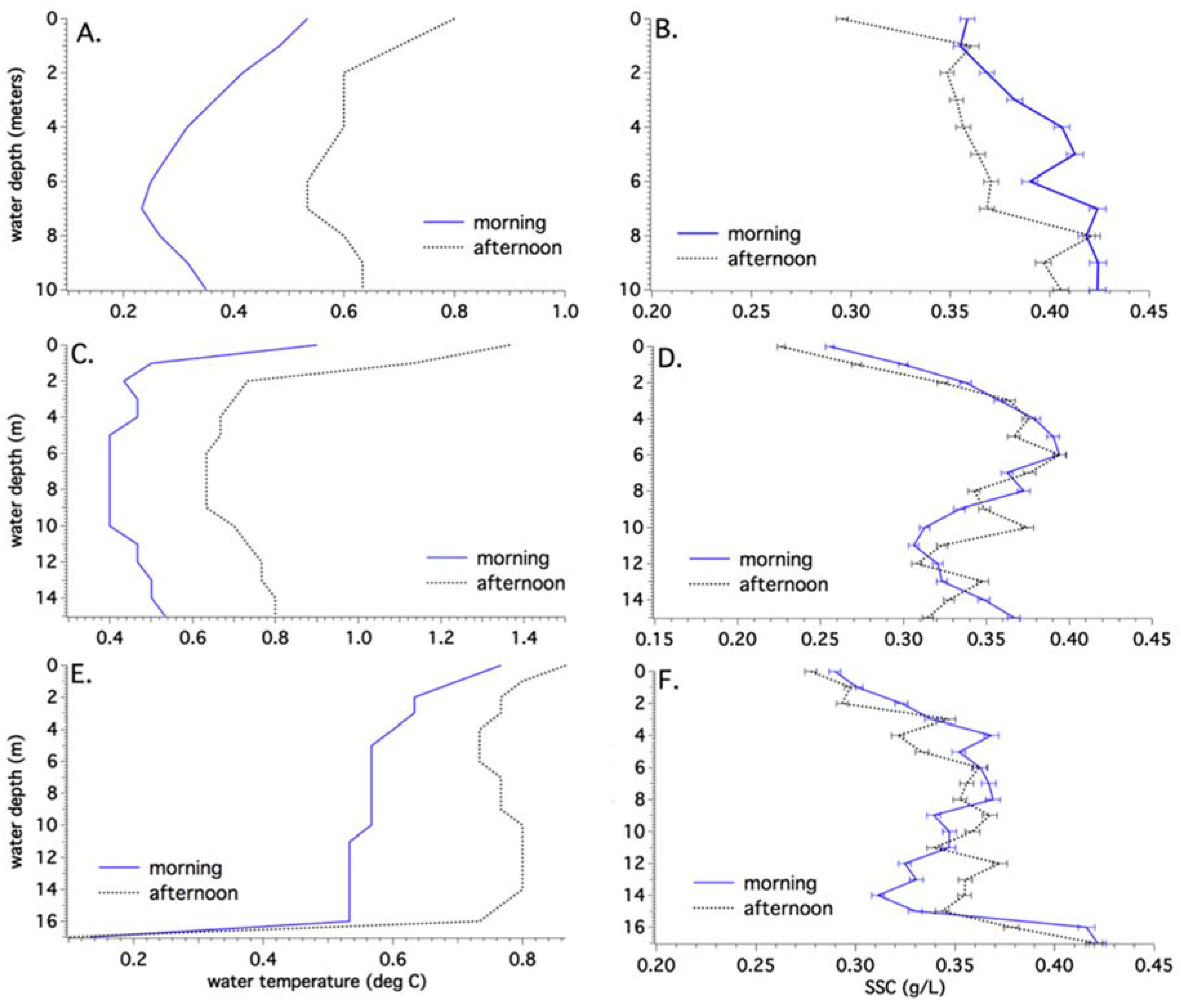
Temperatures and turbidity values (converted to suspended sediment concentration (SSC), as seen in Figure S1) were measured in the vicinity of the buoys for the sub-basins in the mornings and afternoons during the first week of June 2014. Figure 5A,C,E shows the temperature variations with depth for the NW, NE and MB sub-basins, respectively, while Figure 5B,D,F shows the suspended sediment concentration variations. The lines represent morning and afternoon averages for the week.
The general trend is warmer surface temperatures in the afternoon, given solar heating, but overall low temperatures (0.5–1.5 °C). In the NW sub-basin (Figure 5A), temperatures decrease with depth to 7 m and then slightly rise near the bottom. The NE sub-basin (Figure 5C) is isothermal below a 2-m depth, with a slight rise below 10 m to the bottom at 15 m. The MB sub-basin (Figure 5E) is isothermal with depth until reaching 0.1 °C at the bottom, which is interpreted to be either bare ice or a very thin layer of debris covering the ice.
A general trend of an increase in suspended sediment concentration (from ~0.25–0.4 g/L) with depth is seen for the sub-basins, except for the NE, which shows a drop in SSC from a 10–12-m depth. Lower SSC at the surface is attributed to wind-mixing (see Figure S2). This effect can be seen in the NW sub-basin (Figure 5B) when comparing the morning and afternoon SSC levels. The decrease in SSC at depth in the NE sub-basin could be an indication of horizontal clean water intrusions from an englacial channel and/or from the nearby north-facing ice walls, although temperatures slightly rise at this depth.
There are no discernible pycnoclines or thermoclines in the sub-basins. Substituting water density for temperature in Figure 5 reveals that higher density water overlies lower density. For pure water, this condition will cause overturning. Therefore, it must be that in these glacial lakes, the suspended sediment content governs the water density, not temperature. This is similar to the relationship between density and temperature found in the nearby Tsho Rolpa glacial lake [10].
Sieving of dredge samples revealed the finest fraction to be d < 44 µm (clay and silt). Water samples measured from Tsho Rolpa lake had similar grain sizes and increases in SSC with depth, although at twice the concentration (up to 0.8 g/L), attributed to feeder sediment underflows from the large ice calving front [10]. Calmer areas of Tsho Rolpa showed ranges in SSC with depth similar to that recorded here.
Applying Stoke’s law, the settling velocity of clay and silt-sized particles is found to be quite low and results in a settling time range of 2 days–3 weeks per every 10 m in the lake. Given the sub-basin suspended sediment concentration profiles with depth and known settling velocity for particle size, diffusivity can be calculated using:
w s C = ε s ( Δ C / Δ z )
where w s is the settling velocity of the mean grain sizes (m/s), ε s is the diffusivity for suspended sediment and ( Δ C/ Δ z ) is the mean SSC gradient of a size fraction, as seen in [11]. The values here range much higher than molecular thermal diffusivity at 1 × 10⁻⁷ m2/s, suggesting that part of the mixing is due to turbulence, presumably induced by wind and/or calving at the surface and/or thermal currents at depth. NW and Main sub-basin show similar diffusivities and thus likely have similar mixing intensities, while NE and SW (Figure S3) have the highest diffusivities, indicating higher mixing intensity likely due to the proximity of subaerial ice walls for the former and strong currents (0.8–1 m/s) at the latter. The mostly isothermal nature of these sub-basins, in combination with SSC values, suggests an overall well-mixed system during the monsoon. Flocculation of suspended sediment was found to occur in collected water samples, providing a mechanism for increasing settling velocity and, thus, accumulation of these small particles at depth when surface and subsurface melting activity (mixing) slows during the dry season.

4.2. Water Properties

Major elements (Si, Fe, Mg, Ca, Al and Na, in ppm), the trace element arsenic (As, in ppb) and suspended sediment concentration (g/L) were measured in the lab for the sub-basins and surroundings of interest (Table 1), including inflow channels, an ice wall, Spillway’s outflow and a nearby stable blue lake. NE is the least turbid of the sub-basins, but with comparable chemistry. This correlates well with the in situ field measurements. As expected, the ice wall sample has the lowest concentration of these elements, due to minimal mixing with surrounding debris and is characterized by having the clearest water.
Inflow from exposed englacial channels found near NW and NE differ, with the latter possessing significantly less concentrated suspended sediment, at 0.06 g/L; and the former with higher SSC, at 0.22 g/L. The cleaner NE inflow, one of many channels that exist beneath the water’s surface, may help explain the overall low turbidity in the NE sub-basin. High amounts of Si, Fe and Al in the sub-basins are likely due to sediment inputs, while high values of Ca and As in the stable blue lake are likely from weathering of the surrounding leucogranitic rocks, which contain garnet, tourmaline and chalcopyrite. The blue lake’s SSC is the lowest; it has the largest optical depth and the highest As (45 ppb), nearly four-times that found in Spillway Lake. The U.S. Environmental Protection Agency (EPA) sets the safe drinking water limit at 10 ppb of As. Given the proximity of other such blue lakes to hiking trails, care should be taken when drinking this water, although the situation is not as dire as in Bangladesh’s drinking water, where values reach 500 ppb [24].
Sub-basins show similar (basic) pH values and very low conductivity, as expected for these freshwater lakes (Table 2). Optical depth, determined with a Secchi disk, shows equivalent depths for NW, MB and SW. NE’s higher optical depth correlates with its lower turbidity, as measured in the field.

4.3. Annual Temperature Variations

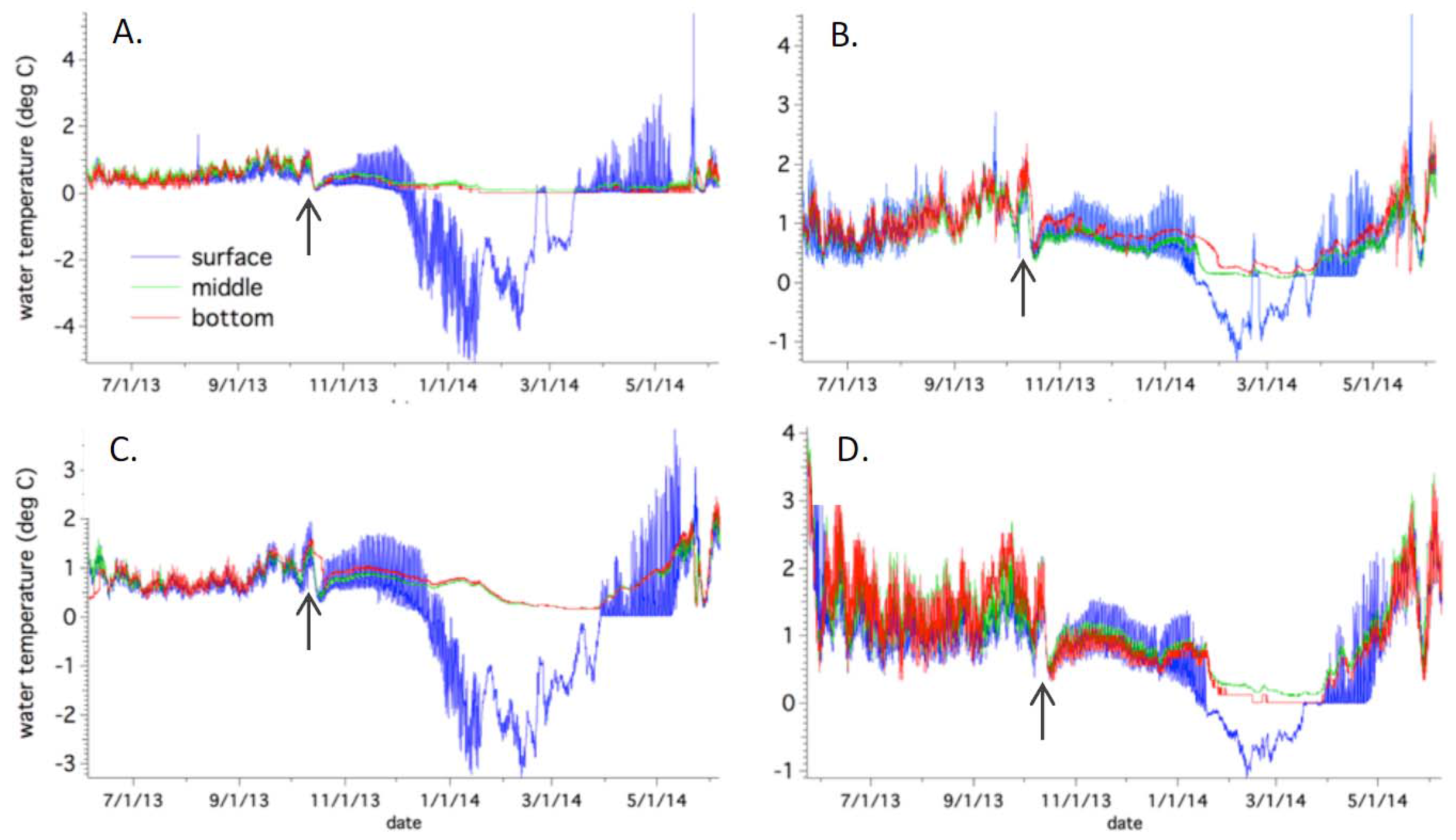
Surface, middle and bottom temperatures were measured for the NW (10-m buoy), NE (15-m buoy), Main (17-m buoy) and SW (3-m buoy) sub-basins from June 2013–June 2014. Figure 6 shows the annual trends for each. NW buoy (A) has the lowest average annual temperatures, at −0.187 °C (surface), due to a long period of ice cover; 0.388 °C (middle); and 0.324 °C (bottom). Its bottom temperatures are the lowest of all of the sub-basins, and it was the last basin to completely thaw. NE buoy (B) is warmer at 0.651 °C (surface); 0.738 °C (middle); and 0.865 °C (bottom); with the bottom temperatures as second warmest, despite the 15-m depth. The Main buoy has annual average temperatures of 0.136 °C (surface), due to long ice cover; 0.706 °C (middle); and 0.747 °C (bottom). The SW buoy is the warmest with annual average surface temperatures of 0.75 °C; 1.02 °C (middle) and 1 °C (bottom). Given the shallow optical depth of these sub-basins, shortwave radiation is unlikely to reach the bottom, as noted on smaller supraglacial ponds on the Khumbu glacier [13,25]. The warmer bottom temperatures at SW are likely due to the shallower depth, while for MB and NE, the presence of an insulating debris layer keeps bottom temperatures warmer.
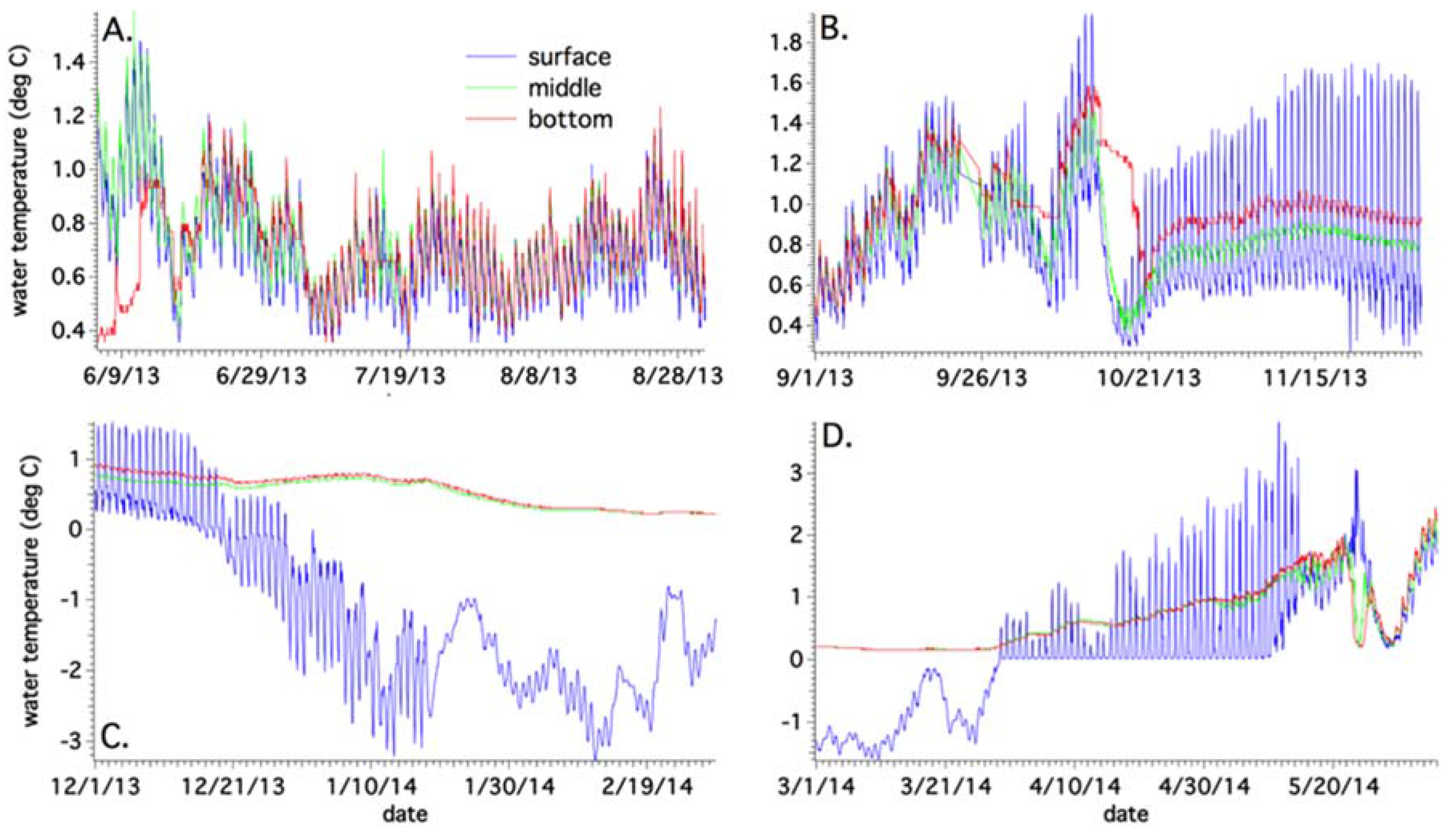
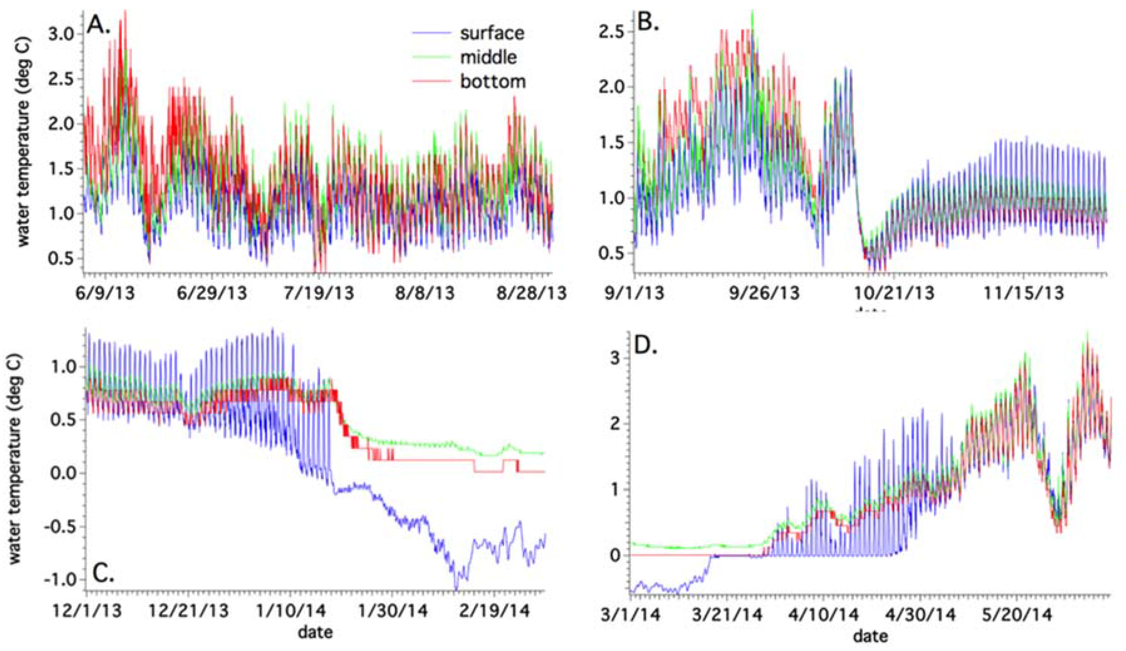
Close-ups of seasonal temperature variations can be seen in Figure 7 and Figure 8 (Figures S4 and S5 for NW sub-basin and NE sub-basin, respectively), showing the deepest (MB) and shallowest (SW) buoy locations. During the summer, bottom temperatures at the MB site reach a maximum of 1.2 °C, while averaging 0.7 °C. Comparatively, SW summer bottom temperatures reach a maximum of 3.26 °C, averaging 1.45 °C.
Both sub-basins reveal similar temperatures from top to bottom, indicating that during the monsoon, the lake is mostly isothermal and well mixed. Inputs include subaerial meltwater from surrounding ice walls, englacial/subglacial sources and precipitation. During the fall, average bottom temperatures increase to 1 °C for MB (max of 1.59 °C) and drop to 1.22 °C (max of 2.5 °C) for the SW site. During this time, due to decreasing air temperatures, subaerial and englacial melting inputs decrease, compared with the summer. SW is able to cool more quickly presumably due to its shallower depth and larger diurnal temperature amplitudes.
Cyclone Phailin dropped one meter of snow in the area in mid-October (2013), leading to a decrease in surface and bottom temperatures, from which point the latter did not recover to pre-cyclone values. During the winter freeze, bottom temperatures remain above zero for both sites (0.57 °C for MB; 0.43 °C for SW). The delay in surface freezing is due to strong (0.8 m/s) surface currents in the vicinity of both buoy locations; these have been documented in the field to persist through late December. During the spring thaw, the surfaces undergo freeze-thaw cycles for most of April, until total thaw of the lakes occurs in early May for MB (see Figure S6 for the time-lapse sequence), while for SW, the thaw occurs a few weeks earlier. Bottom temperatures peak out at 2.45 °C for MB and 3.26 °C for SW, before the water column mixes again at the end of the month. A late season snowstorm accounts for the anomaly seen in the data on 26 May.
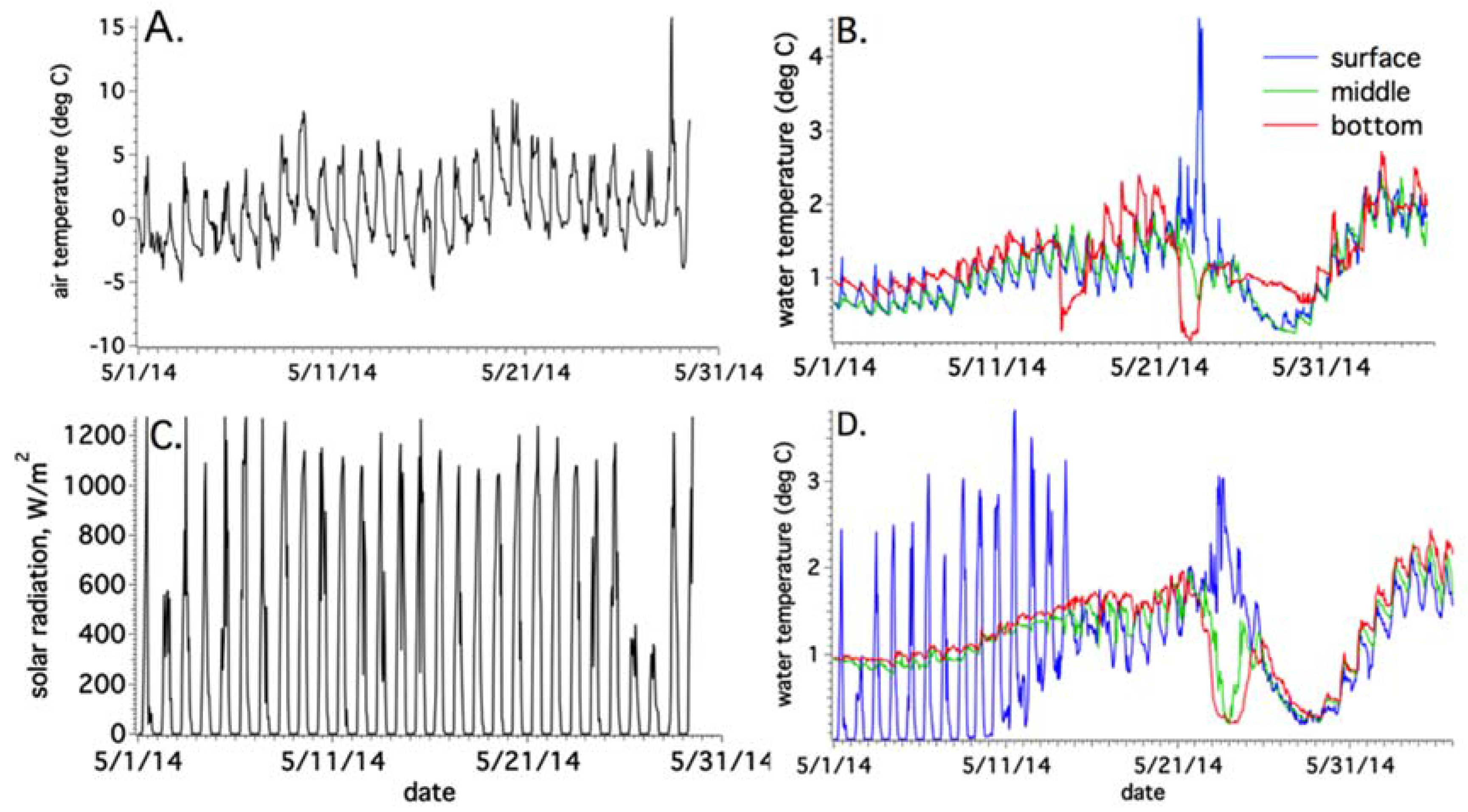
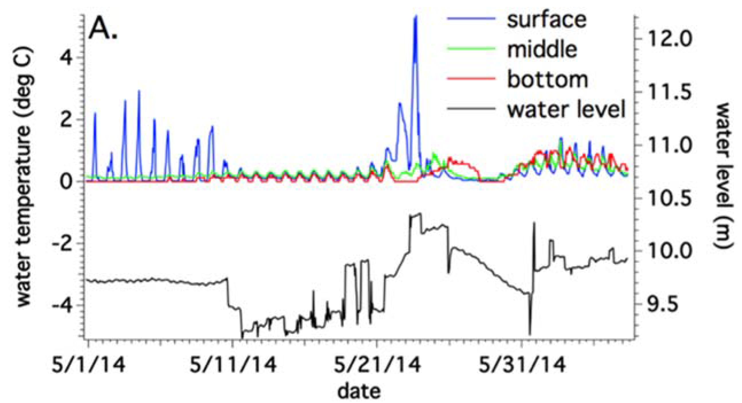
A close-up of May 2014 is seen in Figure 9 for the NE and Main sub-basin buoy locations, along with meteorological data, in order to understand the event that occurred before the 26 May snowstorm (Figure 9C) that led to cold temperatures and mixing throughout the water columns (Figure 9B,D). No anomalous air temperatures were recorded for 23 May (Figure 9A), although NE reached a peak surface temperature of 4.5 °C, and MB saw a comparatively high 3.2 °C. In the former case, this would lead to stratification of the water column, given lower buoyancy of the warm surface water. In the latter case, bottom temperatures of 0.2 °C would be less dense and would want to rise to replace the surface water. The snowstorm interferes with the mixing ‘signal’ in the water column, following this event. However, on 23 May, the middle temperature in the MB sub-basin tracks with the bottom temperature of 0.2 °C, indicating that this may be an englacial/subglacial emergence of meltwater (Figure 9D). The NE sub-basin records a similar 0.2 °C bottom temperature drop, though the middle does not track as clearly as in the MB location. A similar event in NE a week prior shows bottom temperatures again dropping to low values, although not as low as the 23 May event, while the surface remains unchanged. The distance between these sub-basins is approximately 200 m.
Another close-up of May 2014 is shown in Figure 10, in which water temperature and pressure transducer data provide more insight to the 23 May anomaly from the other sub-basins. The NW buoy location shows a more chaotic gain in water level during the spring thaw (Figure 10A). Its proximity to debris-covered ice walls could cause occasional disruptions, yet the overall increasing water level pattern continues from 11 May to 23 May. The same gradual rise is seen in the SW buoy location (Figure 10B). A gain of 0.5 m occurs during the time of the anomaly, though it starts in the NW location at 7 a.m. on 23 May. The gain in SW is more gradual, peaking out a day later. A snowstorm keeps the level high through 26 May, and by the end of the month, both sub-basins return to their pre-gain levels.
Into the first week of June, the gradual rise in water level continues, due to the start of the melting season. While the NE and MB sub-basins saw a signal of englacial/subglacial activity (Figure 9B,D), it is not as evident in NW, given very low bottom temperatures to begin with. SW is a shallow sub-basin, with no ice surroundings. It does not see a sudden drop in bottom temperature on 23 May.

4.4. Sediment Properties and Ice Melt Rates

An Ekman dredge was used to collect samples from the sub-basins, to measure material properties in the lab including grain size, particle density, thermal conductivity, heat capacity and diffusivity. Consistently at the buoy locations, dredged materials included a surface of compacted fine mud, with silt and sand-sized particles and pebbles mixed in with depth. Quantifying thermal conductivity of sediment is important when attempting to model ice melt below debris. Underwater, there is no need to account for meteorological variables, thereby reducing the complexity. Conductive heat flux can be calculated using:
Qc = −k dT/dz
where k is the thermal conductivity of the material (W/m-K), T is the temperature within the sediment layer at some point (z) within that layer (m) and Qc is the downward conductive heat flux. As per [26] and [27], simplifying the temperature gradient to be linear within the debris layer, the equation becomes:
Qc = k(Ts − Ti)/hd
where Ts is the temperature at the surface of the debris and Ti is the temperature of the underlying ice, taken to be 0 °C.
The melt rate can be calculated using:
M = 3.1536 × 10⁷ (Qc/Lρ)
where the constant converts time from seconds to years, Qc is the calculated heat flux; ρ is the density of ice; and L is the latent heat of melting. Debris samples were measured in the lab for their thermal properties (Table S1). The thermal conductivity is ~1.8 W/m-K, close to that found previously (1.7 W/m-K) for debris on the surface of Ngozumpa in [19].
Calculated ice melt rates can be found in Table 3, which compares seasonal rates for the sub-basins for sediment thicknesses varying from 0.1–1 m. The thinner the debris, the faster the ice will melt. The rates are upwards of 10 m/yr in all sub-basins, except for NW, which was the coldest overall basin. At only 10 cm of sediment, ice melt rates are reduced significantly, to less than 2 m/yr. With a 1-m thickness of sediment assumed to line the bottom of Spillway Lake [4], the melting is negligible in all sub-basins, even the warm SW location, for observed annual bottom temperatures.
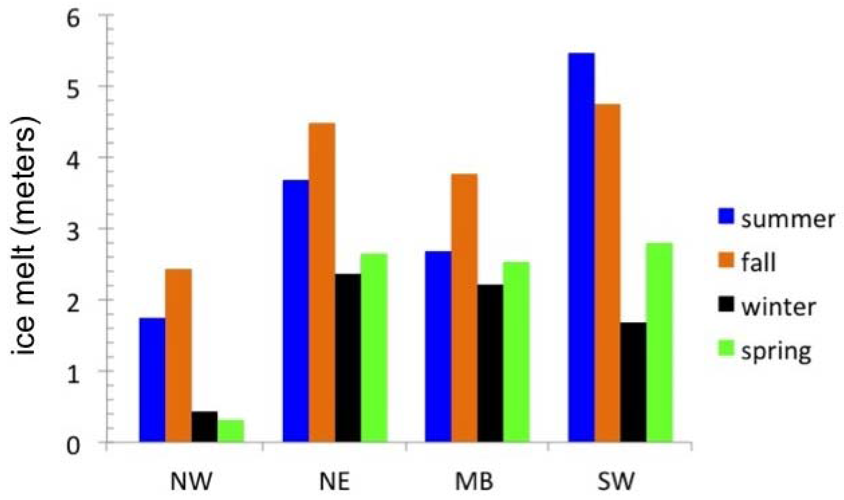
Figure 11 compares the sub-basins across the seasons, using only one debris thickness (1 cm) as an example. In NW, NE and MB, ice melt rates are highest during the fall, while for SW, summer rates are higher. High rates in the SW basin can be attributed to its shallower depth and significant distance away from actively calving and/or melting ice walls. The decline of surface melting in the fall in the other basins aids in heat storage. Winter and spring rates are low in the NW buoy site, given its very cold temperatures throughout. The rates are comparable for the NE and MB. With the addition of an ice cover, heat can be dedicated towards bottom melting. This has been documented by [25] for small supraglacial ponds on the Khumbu glacier.
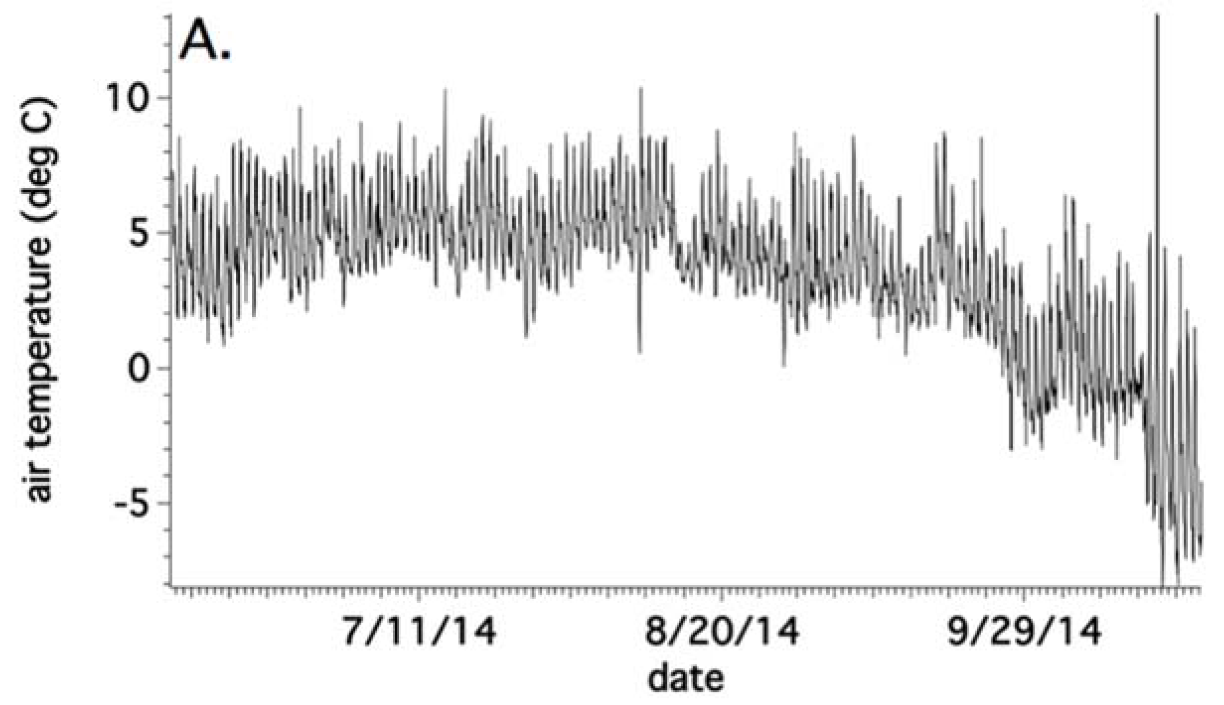
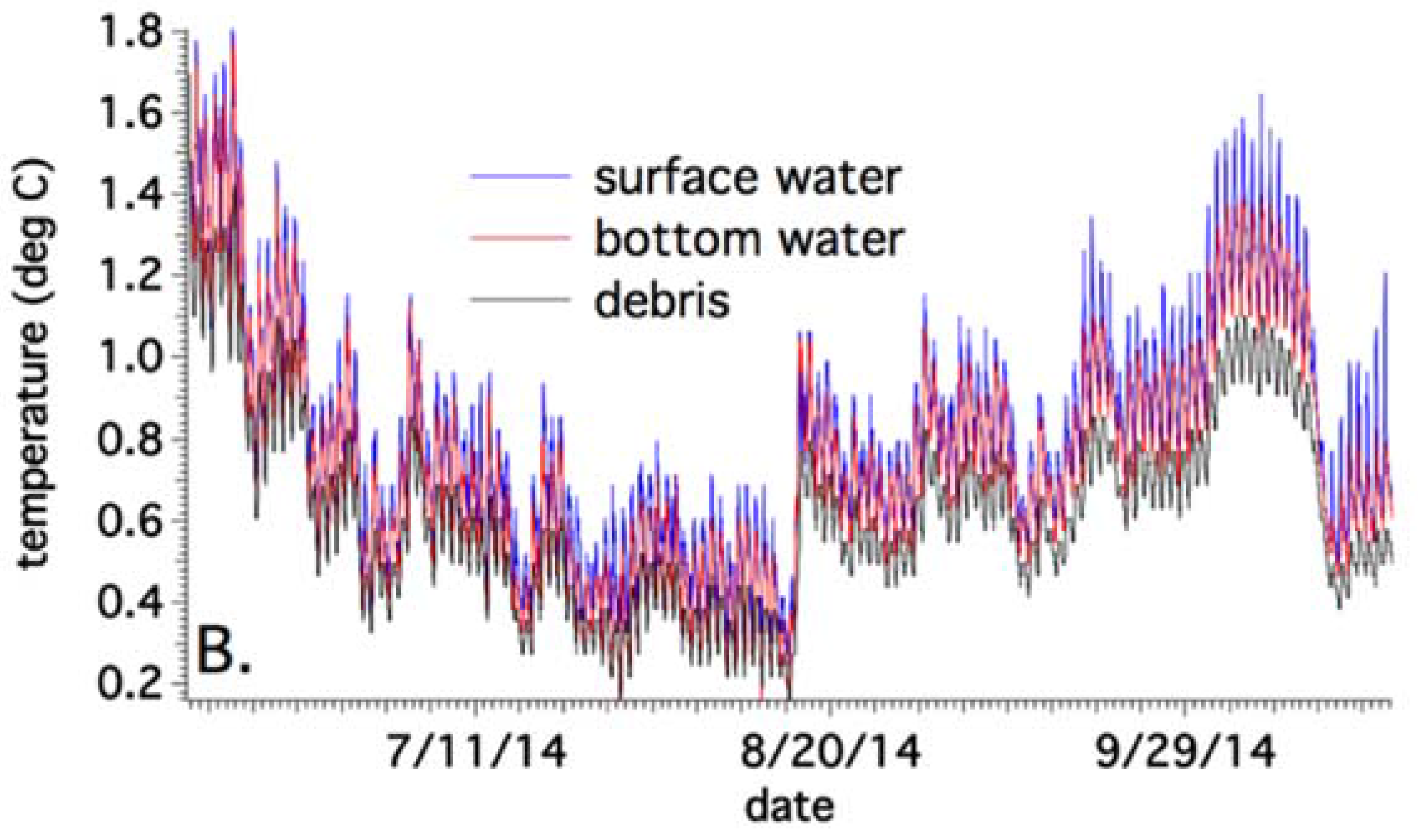
Figure 12 compares June–October 2014 surface and bottom water temperatures in the Main sub-basin, with debris temperature from a sensor buried in a sandbag filled with sediment that had been dredged from the bottom. This buoy was placed within 10 m of a west-facing ice wall. From mid-June–mid-August, temperatures drop from 1.8 down to 0.2 °C, due to the meltwater inputs. No snow was seen in time-lapse imagery in mid-August, when debris and bottom temperatures dropped to 0.2 °C. This indicates an upwelling of englacial/subglacial meltwater. The temperatures begin to rise again from mid-August–mid-October. During this time, air temperatures remained high until August and then started gradually dropping until October. Cyclone Hudhud dropped 30 cm of snow in mid-October 2014, explaining the sudden temperature drop in the water column. The data show an average of 0.75 °C for bottom water temperature and 0.62 °C debris temperature during this timeframe. The 0.15 °C difference implies an overestimate of ice melt using June 2013–June 2014 data.

4.5. Sonar and Structure

An open water bathymetric survey was conducted on the sub-basins (and surrounding smaller ponds) of Spillway Lake in the first week of June 2014, using a 200-kHz dual down and side imaging commercial fish finder, with ±1 m vertical accuracy. A transducer, GPS and handheld unit, powered by a 20-amp-h battery in a waterproof casing, were mounted on a boat and towed by a sea kayak. Lateral position accuracy is estimated as ±0.5 m. The 3D modeling results from the four sub-basins are seen in Figure S7. The NW sub-basin (A) has a maximum depth of 21 m, with a ridge-like structure trending west-east, a relict of the hummocky surface prior to water infill from lake expansion in 2004–2008. Similar relict hummocky terrain is seen in the Main sub-basin (C, maximum depth of 22 m) as lake expansion began in that area in 2004. The NE and SW sub-basins are shallower, at a 15-m and 14-m depth, respectively.
Lake floor roughness can be estimated by acoustic backscatter in the primary echo region (E1 layer). To the side-scan sonar, smooth bottoms, such as compacted muds and sands, act as acoustic mirrors and reflect most of the returning echo away from the receiver. The result is an echo amplitude waveform with a sharp rise and rapid deterioration [22,23]. In contrast, irregular bottom surfaces, consisting of rocks and boulders, reflect sound with multi-path back to the receiver. Thus, these kinds of surfaces will increase the proportion of the total transmitted sound that is reflected back to the transducer. In this case, the waveform rises quickly, but deteriorates slowly. Figure 13 provides an example of open-water data collected in the Main sub-basin of Spillway Lake.
To determine bottom hardness, the secondary echo region (E2) can be used. This is a measure of the acoustic absorption or impedance of the bottom. Mud and materials with high water content will absorb a large proportion of the transmitted acoustic energy, reducing the echo amplitude, whereas hard substrates will reflect a greater proportion of the transmitted energy, resulting in high amplitude secondary echoes [22,23]. In cases where E2 returns are not picked up, due to insufficient depth, peak Sv is used instead. This is calculated from the primary echo and defined as the observed maximum volumetric backscatter (Sv) of all of the acoustic samples within the layer between the sounder detected bottom and the bottom of the E1 layer.
It is important to note that E1, E2 and peak Sv provide only a relative measure of substrate roughness and hardness. The measurements are highly influenced by the acoustic footprint size, thus limiting the ability to resolve changes with increasing water depth. E2 measurements rely on sound reflections from the lake surface and so are influenced by wind and wave conditions. For this reason, the four sub-basins cannot be compared with each other (rockier, harder, etc.).
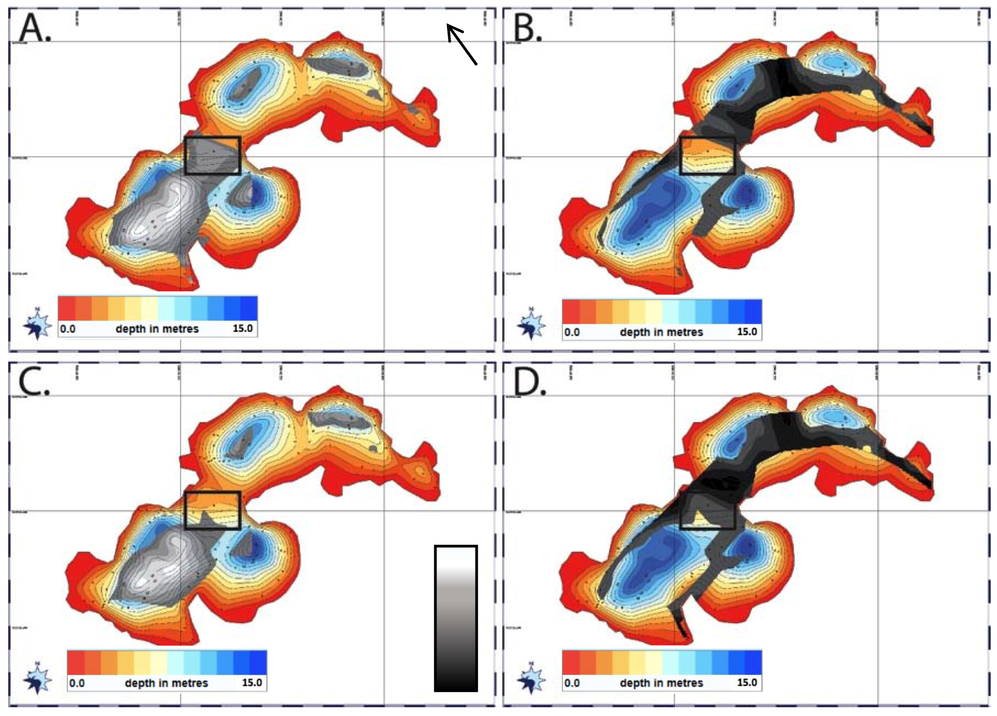
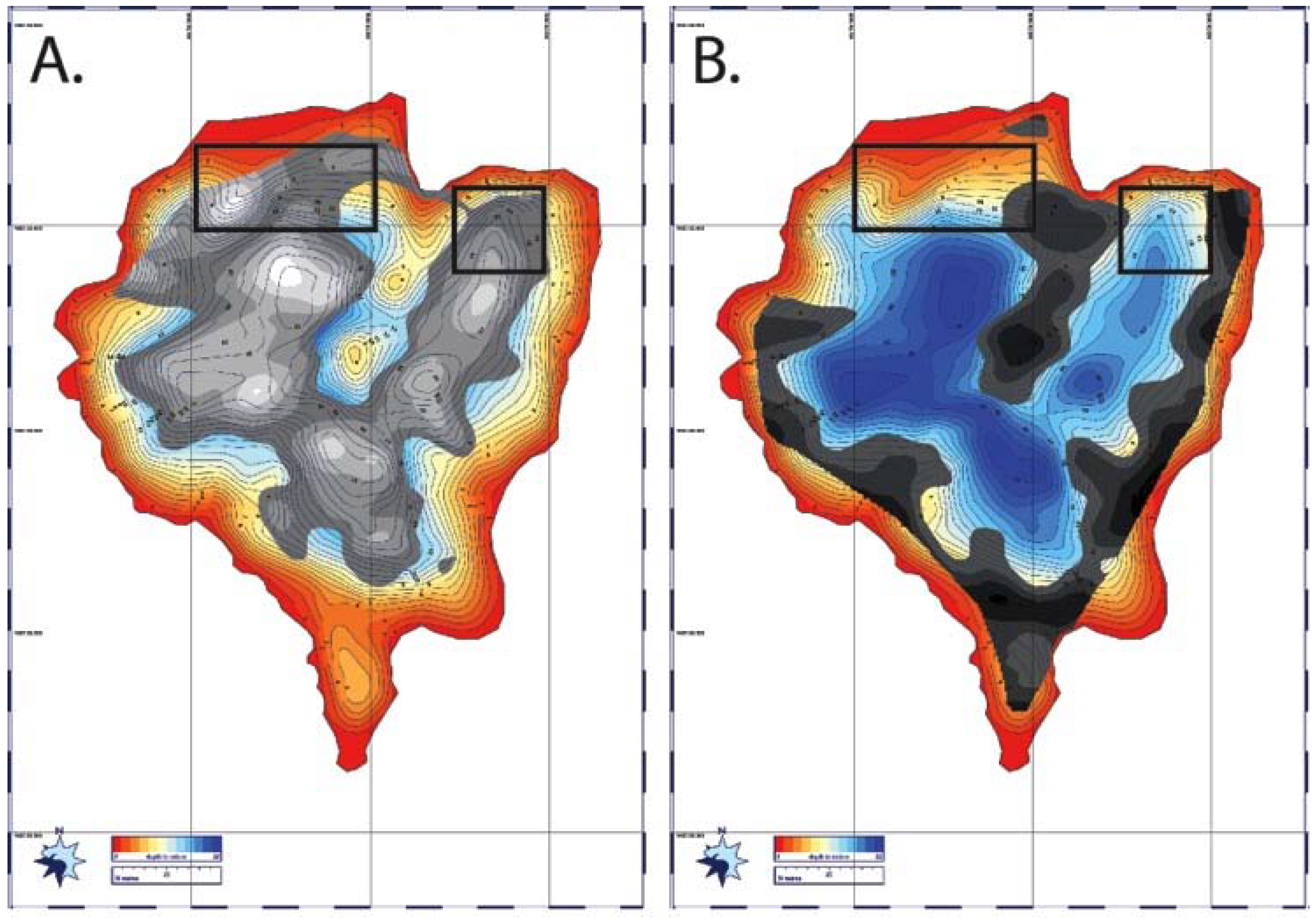
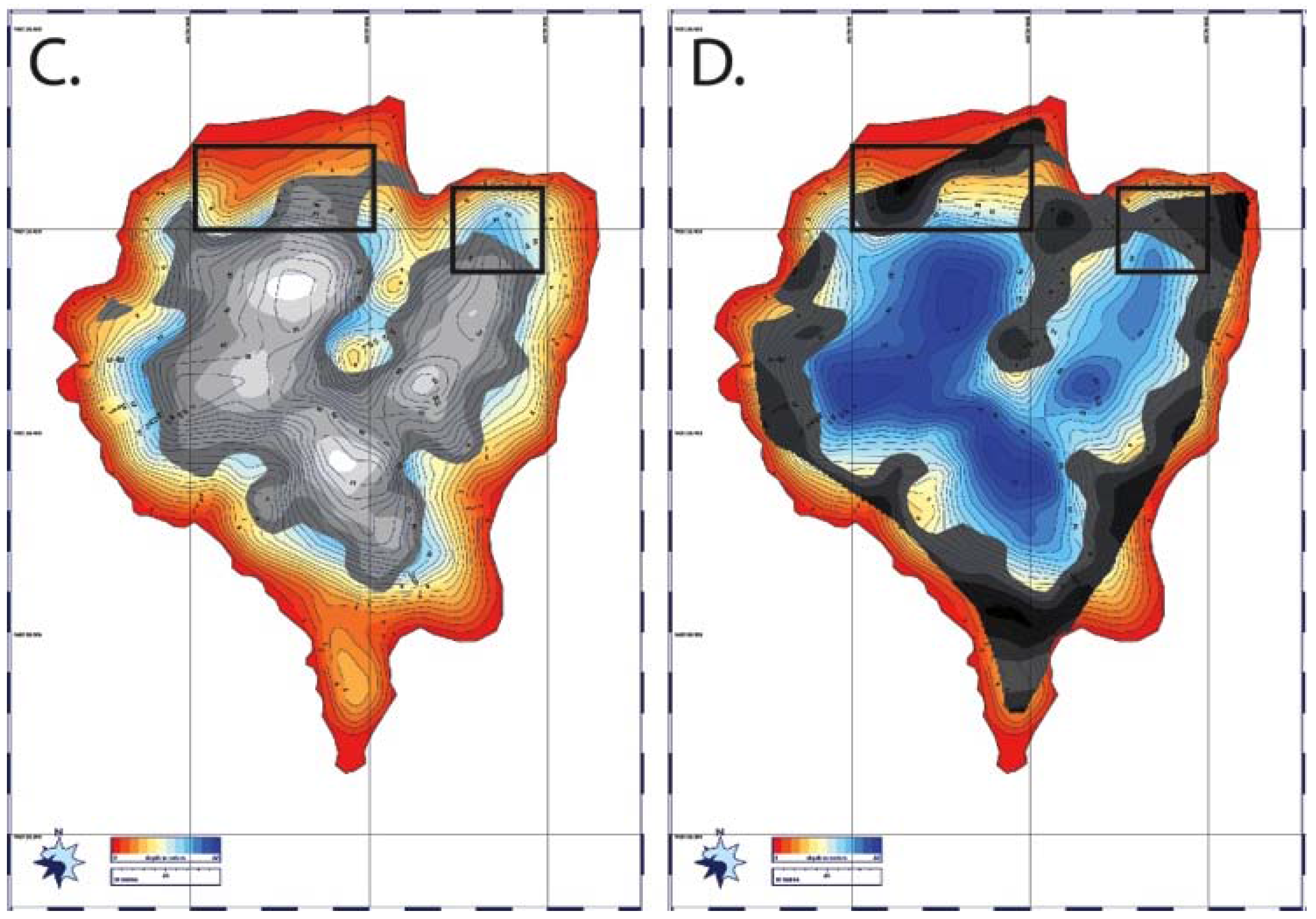
Figure 14 and Figure 15 show NE and Main sub-basin E1 and peak Sv maps (Figures S8 and S9 for NW and SW sub-basins). In both cases, (A) reveals smooth substrate from the E1 return, while (C) shows soft substrate from the calculated peak Sv. (B) and (D) show rocky (E1) and hard (peak Sv), respectively. Rocky and hard returns in Figure 14B,D are seen in the eastern sector and correlate well with recent shallowing.
Rocky and hard returns in MB (Figure 15B,D) are seen along the shore and on the hummocky shallower terrain in the middle of the basin. Overlain black boxes highlight areas with smooth (A) and hard (D) returns, which reveal areas of bare or nearly bare ice. More field data are needed to validate these results using seismic and/or ground-penetrating radar. However, in the case of the Main sub-basin, vertical temperature measurements (Figure 5) showed 0.1 °C at the bottom, while field photos (Figure S10) show upwelling activity in the region, likely pointing to an active englacial/subglacial input and near-bare ice in the region.

5. Discussion

5.1. Sub-Basins of Spillway

The NW buoy location, at a 10-m depth, recorded the coldest annual temperatures from top to bottom. This cold, turbid sub-basin emerged in 2004 and began expanding towards the north beginning in 2008. South-facing ice walls were actively calving in 2009/2010, during initial survey work as seen in [4]. Upon return to the field site in 2012, the walls were found to be covered with thick debris. Extensive and high amounts of shallowing in the sub-basin from 2009–2012 are interpreted to represent the fall of debris (rocks) into the water. The area of deepening towards the west did so at rates of ~1.5–5 m/yr. Using bottom temperatures for NW, this can be achieved with 1–5 cm of sediment cover. This is plausible, given the relatively young age (five years) of the sub-basin. Enhanced water mixing due to calving and debris falls can also contribute to potentially warmer temperatures at depth, although a sensor near a melting/calving ice wall in the Main sub-basin (June–October 2014; Figure 12B) recorded very low surface and bottom temperatures during the melting season.
The NE buoy location, at a 15-m depth, was the second warmest sub-basin. It was optically the clearest, as well (Table 2). The emergence of the main body of this sub-basin was in 2008, with growth of the eastern sector documented in 2009 and west-facing ice walls observed in 2010. The ice walls in the eastern sector have since been covered with debris. Rough and hard sonar returns in the vicinity (Figure 14B,D) possibly signify debris collapse into the basin. The deepening in certain locations here is on the order of 3–5 m/yr. Using the bottom water temperatures, achieving this rate requires <5 cm of debris, which is possible given the relatively young age (five years) of the basin, in certain spot locations.
The Main buoy location was in 17 m of water. The emergence of the southern sector started in 2001, with northward expansion beginning in 2004. Northwestern expansion began in 2008. Thus, the oldest part of the sub-basin is in the south, while the youngest is towards the NW. The sonar returns, as seen in Figure 15, reveal smooth and soft surfaces in the deep, older areas of the basin, here interpreted to be mud. Sonar returns and substrate classification in the younger parts of the sub-basin point to hard and smooth surfaces, and more research is needed to determine whether or not this is bare ice. However, this would correlate well with the high (5–7 m/yr) deepening rates in the region. Using the recorded bottom water temperatures, achieving these deepening rates in the older region of the basin would requires <5 cm of debris. However, given the age of the basin (13 years), there should have been sufficient time to accumulate thick debris. Documented flow currents of >1 m/s, even late into the dry season in the narrow region connecting Main to SW, can potentially extend the settling time of particles in this basin and/or bottom currents can potentially lead to lake floor scouring of debris.
The SW buoy location was in 3 m of water and the warmest overall location. This sub-basin is the oldest, at 13 years, and has remained a shallow/stable region during this time [4]. While the bottom temperatures recorded here can lead to the highest ice melt rates, sediment thickness is likely very high. A 0.3 m/yr sedimentation rate was documented in this region [4]. The bottom temperatures at a shallow depth can still be used as a proxy for other shallow regions in the vicinity of the SW basin and can help explain (limited) shoreline degradation in the region since 2001.

5.2. Tsho Rolpa, Imja and Spillway

Investigations at Tsho Rolpa revealed vigorous circulation of surface water due to wind-driven currents across a 3-km fetch, as well as an established thermocline at 25 m and weak pycnocline [10]. This allows for heat transfer between water and ice along the calving front and on the thinly sediment-covered lake ice floor. Warm mean annual water temperatures (2–3 °C) and heat conduction through sediments can lead to melting and deepening of the ice floor on Tsho Rolpa at much faster rates than Spillway, given these higher temperatures. No thermocline was observed at Imja, indicating that wind mixing is not as prevalent. It is an isothermal lake, at 3 °C, which may encourage higher rates of dead-ice melt through a sediment layer. Despite the capacity for mixing, given strong valley winds, the presence of extensive dead ice near the terminus, as well as elevated debris islands results in roughness and turbulence, thereby lessening mixing in Imja given these structures can behave as energy dissipaters, shielding the lake from wind [11,20].
Spillway Lake is comparatively shallow (Tsho Rolpa’s thermocline is at Spillway’s maximum depth), with a much smaller fetch (300 m compared with 3 km) and no established thermocline or pycnocline. Rather than a calving front, the lake is surrounded by ice walls and is fed by multiple supraglacial, englacial and possibly subglacial channel inputs. Although comparably strong valley winds blow during the summer, hummocky terrain and multiple debris islands dotted between the sub-basins, especially between Main and NW sub-basins, likely result in high roughness and turbulence, like that seen on Imja, minimizing the wind effect.
Subaqueous calving events, as readily observed on the debris-covered Tasman glacier (New Zealand), can lead to rapid deepening and destabilization [28]. It is unknown how frequently this occurs on Himalayan debris-covered glaciers [16]. No instances of subaqueous calving were observed in our time-lapse cameras during 2013–2014, although that does not mean it does not occur.

6. Conclusions

Precise 4D measurements of temperature and associated water opacity, sediment concentration and water depth over two seasons of snow accumulation and melt have elucidated several features that appear important in governing the depth and areal expansion of supraglacial lakes. Spillway Lake on Ngozumpa glacier affords a view of contrasting processes from which we may forecast the future development of Spillway and other similar lakes.
In areas of very thick sediment cover, like the older southern region of Spillway, bottom deepening is expected to be minimal, although expansion can continue towards the north and west, exploiting weaknesses (cracks) in the terrain. In younger parts of the lake, especially in the NE sub-basin with actively melting and calving north-facing ice walls, less time to accumulate debris and higher ice melt rates under this thinner debris means that deepening rates are expected to continue to increase. In the Main sub-basin, despite older and younger regions, deepening is continuing at the highest rate in Spillway Lake. More information is needed, in the form of seismic or radar survey, to better quantify debris thickness and to detect the presence of bare ice in this region, while current-meters set at depth can be used to quantify the flow associated with englacial and subglacial inputs. Higher resolution multi-beam sonar surveys could prove useful in mapping subaqueous ice cliffs in the vicinity of calving ice walls. In view of the danger from large waves associated with calving during the measurements, unmanned remotely steerable sensor platforms offer advantages for future survey work.

Supplementary Materials

The following are available online at www.mdpi.com/2073-4441/9/5/362, Figure S1: Conversion of field and lab-measured turbidity values (nephelometric turbidity units (NTU)) to suspended sediment concentration (SSC) in g/L; Figure S2. Wind direction (red) and wind speed (black) data subset from June 2014. General trends include highest wind speeds (>5 m/s) in the afternoon, starting at 12 p.m. During the day, wind direction (~130°) comes via valley winds from the southeast. At night, wind direction (~250–300°), and speed (<2 m/s) switch to weaker northwesterly mountain downdrafts; Figure S3. SW sub-basin temperature (A) and suspended sediment concentration (B) with depth. Shallow depth leads to much higher overall temperatures from top to bottom. Similar to the other sub-basins, SSC increases with depth, indicating a stable density structure; Figure S4. Seasonal temperature variations in NW sub-basin buoy location for the monsoon (A), fall (B), winter (C) and spring (D). Surface in blue; middle in green; bottom in red; Figure S5. Seasonal temperature variations in NE sub-basin buoy location for the monsoon (A), fall (B), winter (C) and spring (D). Surface in blue; middle in green; bottom in red; Figure S6. Time-lapse sequence of the Main sub-basin thaw from 11 May–19 May 2014; Figure S7. Derived 3D models of the sub-basins, with 2–3 × vertical exaggeration. NW sub-basin (A); NE sub-basin (B); Main sub-basin (C) and SW sub-basin with surroundings (D); Figure S8. NW sub-basin roughness and hardness maps, generated from E1 and peak Sv acoustic backscatter values. Smooth (A), rough (B), soft (C) and hard (D) are shown; Figure S9. Zoom-in of SW sub-basin roughness and hardness maps, generated from E1 and peak Sv acoustic backscatter values. Smooth (A) and soft (B) are shown, showing good overlap and consistent with high sedimentation rates in this region; Figure S10. Frozen-over upwelling (December 2013) in the northeastern part of Main basin, Spillway Lake; Table S1: Six samples (one from each sub-basin and two extra within the Main sub-basin) and the average values for thermal conductivity (k), thermal resistivity (rho), volumetric heat capacity (C) and thermal diffusivity (D), with error.

Acknowledgments

The author wishes to thank the U.S. Fulbright Program; a USAID HiMAP climber-scientist grant; The Geological Society of America; the National Snow and Ice Data Center (Richard Armstrong); and crowd fundraising supporters, namely Adrian Sheremeta; Arthur Few; Benjamin Diedrich; Jeff Daulton; and John Cassese (www.petridish.org (no longer in operation)) for providing the funds to complete this research. The author is indebted to Patrick Rowe (Midwest ROV LLC) and the Milwaukee School of Engineering; Roger Bilham (University of Colorado Boulder); and David Breashears (GlacierWorks) for their technical and field assistance. Thanks to Emma Marcucci, Daniel Zietlow, Cecil Goodson, Sam Ecenia and David Byrne for assistance with collection of water and mud samples; deployment of temperature buoys and weather stations; and assistance with rowing of a hand-powered kayak for initial open-water sonar transect data collection. Thank you to Lhakpa Nuru Sherpa for hospitality at the Cho La Pass Resort in Tangnak, Nepal during the field work; Amrit Thapa (Epic Himalaya) for logistical support; Benjamin Pothier (Paris, France) for filming on-location; The Crowd & The Cloud PBS citizen science series for featuring our work with the Sherpa-Scientist Initiative; and laboratory facilities at the Colorado School of Mines and University of Colorado Boulder (Fred Luiszer). Helpful conversations with Doug Benn and Sarah Thompson proved invaluable for the completion of this study.

Conflicts of Interest

The authors declare no conflict of interest.

References

  1. Yamada, T. Glacier Lake and Its Outburst Flood in the Nepal Himalaya. Monograph No. 1. Data Centre for Glacier Research; Japanese Society of Snow and Ice: Tokyo, Japan, 1998; p. 96. [Google Scholar]
  2. Komori, J. Recent expansion of glacial lakes in Bhutan Himalayas. Quat. Int. 2008, 184, 177–186. [Google Scholar] [CrossRef]
  3. Sakai, A.; Nishimura, K.; Kadota, T.; Takeuchi, T. Onset of calving at supraglacial lakes on debris-covered glaciers of the Nepal Himalaya. J. Glaciol. 2009, 55, 909–917. [Google Scholar] [CrossRef]
  4. Thompson, S.; Benn, D.I.; Dennis, K.; Luckman, A. A rapidly growing moraine dammed glacial lake on Ngozumpa Glacier, Nepal. Geomorphology 2012, 75, 266–280. [Google Scholar] [CrossRef]
  5. Shrestha, A.B.; Wake, C.P.; Mayewski, P.A.; Dibb, J.E. Maximum temperature trends in the Himalaya and vicinity: An analysis based on temperature records from Nepal for the period 1971–94. J. Clim. 1999, 12, 2775–2786. [Google Scholar] [CrossRef]
  6. Kadota, T. Report for the Field Investigation on the Tsho Rolpa Glacier Lake, Rolwaling Valley, February 1993–June 1994; WECS: Kathmandu, Nepal, 1994. [Google Scholar]
  7. Richardson, S.D.; Reynolds, J.M. An overview of glacial hazards in the Himalayas. Quat. Int. 2000, 65, 31–47. [Google Scholar] [CrossRef]
  8. Reynolds, J.M. On the Formation of Supraglacial Lakes on Debris-Covered Glaciers. Proceedings of Symposium at Seattle 2000—Debris Covered Glaciers, Seattle, WA, USA, September 2000; International Association of Hydrological Sciences Publication: Seattle, WA, USA, 2000; Volume 264, pp. 153–161. [Google Scholar]
  9. Quincey, D.J.; Richardson, S.D.; Luckman, A.; Lucas, R.M.; Reynolds, J.M.; Hambrey, M.J.; Glasser, N.F. Early recognition of glacial lake hazards in the Himalaya using remote sensing datasets. Glob. Planet. Chang. 2007, 56, 137–152. [Google Scholar] [CrossRef]
  10. Chikita, K.A.; Jha, J.; Yamada, T. Hydrodynamics of a supraglacial lake and its effect on the basin expansion: Tsho Rolpa, Rolwaling Valley, Nepal Himalaya. Arct. Antarct. Alp. Res. 1999, 31, 58–70. [Google Scholar] [CrossRef]
  11. Chikita, K.A.; Jha, J.; Yamada, T. Sedimentary effects on the expansion of a Himalayan supraglacial lake. Glob. Planet. Chang. 2001, 28, 23–34. [Google Scholar] [CrossRef]
  12. Watanabe, T.; Kameyama, S.; Sato, T. Imja glacier dead-ice melt rates and changes in a supraglacial lake, 1989–1994, Khumbu Himal, Nepal: Danger of lake drainage. Mt. Res. Dev. 1995, 15, 293–300. [Google Scholar] [CrossRef]
  13. Sakai, A.; Chikita, K.; Yamada, T. Expansion of a moraine-dammed lake, Tsho Rolpa, in Rolwaling Himal, Nepal Himalaya. Limnol. Oceanogr. 2000, 45, 1401–1408. [Google Scholar] [CrossRef]
  14. Fujita, K.; Sakai, A.; Nuimura, T.; Yamaguchi, S.; Sharma, R.R. Recent changes in Imja glacial lake and its damming moraine in the Nepal Himalaya revealed by in situ surveys and multi-temporal ASTER imagery. Environ. Res. Lett. 2009, 4, 045205. [Google Scholar] [CrossRef]
  15. Hambrey, M.J.; Quincey, D.J.; Glasser, N.F.; Reynolds, J.M.; Richardson, S.D.; Clemmens, S. Sedimentological, geomorphological and dynamic context of debris mantled glaciers, Mount Everest region, Nepal. Quat. Sci. Rev. 2008, 27, 2361–2389. [Google Scholar] [CrossRef]
  16. Benn, D.I.; Bolch, T.; Hands, K.; Gulley, J.; Luckman, A.; Nicholson, L.I.; Quincey, D.; Thompson, S.; Toumi, R.; Wiseman, S. Response of debris-covered glaciers in the Mt. Everest region to recent warming, and implications for outburst flood hazards. Earth-Sci. Rev. 2012, 114, 156–174. [Google Scholar]
  17. Benn, D.I.; Wiseman, S.; Hands, K.A. Growth and drainage of supraglacial lakes on the debris-mantled Ngozumpa Glacier, Khumbu Himal, Nepal. J. Glaciol. 2001, 47, 626–638. [Google Scholar] [CrossRef]
  18. Thompson, S.; Benn, D.I.; Mertes, J.; Luckman, A. Stagnation and mass loss on a Himalayan debris-covered glacier: Processes, patterns and rates. J. Glaciol. 2016, 62, 467–485. [Google Scholar] [CrossRef]
  19. Nicholson, L.A.; Benn, D.I. Calculating ice melt beneath a debris layer using meteorological data. J. Glaciol. 2006, 52, 463–470. [Google Scholar] [CrossRef]
  20. Chikita, K.A.; Yamada, T. The expansion of Himalayan glacial lakes due to global warming: Field observations and numerical simulation. In Regional Hydrological Impacts of Climatic Change – Impact Assessment and Decision Making in Seventh IAHS Scientific Assembly; IAHS Publication 295: Foz do Iguacu, Brazil, 2005. [Google Scholar]
  21. Preisendorfer, R.W. Secchi disk science: Visual optics of natural waters. Limnol. Oceanogr. 1986, 31, 909–926. [Google Scholar] [CrossRef]
  22. Chivers, R.C.; Emerson, N.; Burns, D.R. New acoustic processing for underway surveying. Hydrogr. J. 1990, 56, 8–17. [Google Scholar]
  23. Kloser, R.J.; Bax, N.J.; Ryan, T.; Williams, A.; Barker, B.A. Remote sensing of seabed types in the Australian Southeast Fishery; development and application of normal-incident acoustic techniques and associated ground truthing. Mar. Freshw. Res. 2001, 52, 475–489. [Google Scholar] [CrossRef]
  24. Smith, A.H.; Lingas, E.O.; Rahman, M. Contamination of drinking water by arsenic in Bangladesh: A public health emergency. Bull. World Health Organ. 2000, 78, 1093–1103. [Google Scholar] [PubMed]
  25. Sakai, A.; Takeuchi, N.; Fujita, K.; Nakawo, M. Role of Supraglacial Ponds in the Ablation Process of a Debris-Covered Glacier in the Nepal Himalayas. Proceedings of Symposium at Seattle 2000—Debris Covered Glaciers, Seattle, WA, USA, September 2000; International Association of Hydrological Sciences: Seattle, WA, USA, 2000; Volume 264, pp. 119–130. [Google Scholar]
  26. Kraus, H. An Energy Balance Model for Ablation in Mountainous Areas. Proceedings of Snow and Ice Symposium, Moscow, Russia, August 1971; IAHS Publication: Moscow, Russia, 1975; pp. 74–82. [Google Scholar]
  27. Nakawo, M.; Young, G.J. Field experiments to determine the effect of a debris layer on ablation of glacier ice. Ann. Glaciol. 1981, 2, 85–91. [Google Scholar] [CrossRef]
  28. Röhl, K. Characteristics and evolution of supraglacial ponds on debris-covered Tasman Glacier, New Zealand. J. Glaciol. 2008, 54, 867–880. [Google Scholar] [CrossRef]
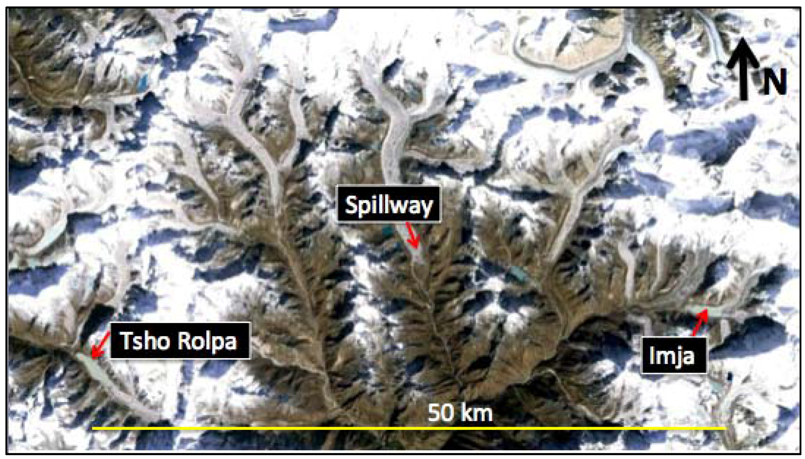
Figure 1. Overview map of the Khumbu region (April 2013 Landsat) showing Tsho Rolpa Lake (NW-flowing Trakarding glacier) in the Rowaling Valley; Spillway Lake (SE-flowing Ngozumpa glacier) in the Gokyo Valley; and Imja Lake (W-flowing Imja glacier) in the Khumbu Valley.
Water 09 00362 g001
Figure 2. Ngozumpa glacier’s terminal moraine and western outlet stream. Boulders along the outlet are a testament to previous floods in the area.
Water 09 00362 g002
Figure 3. The evolution of Spillway Lake’s sub-basins since 2001 (A) and depth map from the original 2009/2010 survey work (B). Adapted from [4], with permission from © Elsevier (Geomorphology).
Water 09 00362 g003
Figure 4. 2016 GeoEye high-resolution image of Ngozumpa glacier (A) with Spillway Lake close-up (B), showing temperature buoy locations for this study in the sub-basins (yellow: northwest; green: northeast; red: main; blue: southwest), weather station (white square) and glacier outlet channel (yellow arrow).
Water 09 00362 g004
Figure 5. Vertical temperature and turbidity variations in the NW (A,B), NE (C,D) and Main sub-basin (E,F). The blue line is indicative of morning averages, while the black dotted line represents afternoon averages.
Water 09 00362 g005
Figure 6. Annual temperatures at the surface (in blue), middle (in green), and bottom (in red) for each sub-basin from 01 June 2013 to 01 June 2014. (A) NW buoy; (B) NE buoy; (C) MB (Main basin) buoy; and (D) SW buoy. The arrows in each show the arrival of Cyclone Phailin (October 2013).
Water 09 00362 g006
Figure 7. Seasonal temperature variations in the Main sub-basin buoy location for the summer/monsoon (A), fall (B), winter (C) and spring (D). Surface in blue; middle in green; bottom in red.
Water 09 00362 g007
Figure 8. Seasonal temperature variations in the SW sub-basin buoy location for the summer/monsoon (A), fall (B), winter (C) and spring (D). Surface in blue; middle in green; bottom in red.
Water 09 00362 g008
Figure 9. Air temperatures (A) and solar radiation (C) during May 2014. Temperatures do not reach their peak until later in the month. Solar radiation remains high (>1000 W/m2) during the month, but the 26 May snowstorm drops this to <400 W/m2. Zoom-ins of the NE buoy location (B) and the Main buoy location (D) for May 2014 show anomalous bottom water temperatures on 23 May.
Water 09 00362 g009
Figure 10. Surface (blue), middle (green) and bottom (red) water temperatures for NW (A) and SW (B) buoy locations. Pressure transducer data reveal a steady rise in water level at the SW site during the spring thaw, with a more chaotic gain seen in NW.
Water 09 00362 g010aWater 09 00362 g010b
Figure 11. Ice melt (meters) for the sub-basins during the summer (blue), fall (orange), winter (black) and spring (green), using 1 cm of debris thickness.
Water 09 00362 g011
Figure 12. Air temperatures (A) and surface (blue), bottom (red) water temperatures and debris (black) temperatures (B) were measured in the Main sub-basin from June–October 2014.
Water 09 00362 g012aWater 09 00362 g012b
Figure 13. Sample sonar image from the Main sub-basin of Spillway Lake, showing the primary echo (E1 layer), which measures roughness (the signal can be mirrored back or take a multi-path), and the secondary (peak Sv layer) echo, which measures hardness based on the material’s acoustic absorption. The former shows sonar returns corresponding with color-coded dots. The darker, the rougher, in a relative scale.
Water 09 00362 g013
Figure 14. NE sub-basin roughness and hardness maps, generated from E1 and peak Sv acoustic backscatter values. Scaled smooth (A), rough (B), soft (C) and hard (D) are shown, with boxes overlain to show smooth-hard returns, interpreted to be bare ice.
Water 09 00362 g014
Figure 15. Main sub-basin roughness and hardness maps, generated from E1 and peak Sv acoustic backscatter values. Smooth (A), rough (B), soft (C) and hard (D) are shown, with boxes overlain to show smooth-hard returns (A,D), interpreted to be bare ice.
Water 09 00362 g015aWater 09 00362 g015b
Table 1. Major and trace (As) elements and suspended sediment concentration (SSC) values from locations in and around Spillway Lake.
SamplesSi (ppm)Fe (ppm)Mg (ppm)Ca (ppm)Al (ppm)Na (ppm)As (ppm)SSC (g/L)
NW basin14.887.002.8010.438.0012.1013.4650.43
NW inflow18.640.150.2412.930.310.6110.8730.22
Ice wall4.320.120.080.640.200.23DL0.07
NE basin20.815.621.9310.7310.0316.2313.7630.21
NE inflow12.930.020.3315.730.040.340.8800.06
Main basin16.574.691.7110.008.0025.1316.3630.40
SW basin22.186.182.1411.1510.9919.7714.3930.40
Outflow15.966.003.0011.089.0013.6014.6810.46
Blue lake2.920.190.2720.060.4019.7345.4560.04
Table 2. Water properties for the sub-basins of Spillway Lake. Values of pH and conductivity were averaged with depth.
Sub-basinpHConductivity (µS)Optical Depth (cm)
NW basin8.5968.8718
NE basin8.3970.3732
Main basin8.2169.2317.5
SW basin8.3268.4715
Table 3. Seasonal ice melt rates (m/yr) for the sub-basins, with simulated debris thicknesses.
Sub-basinDebris Thickness (m)Seasonal Bottom Ice Melt (in Meters)
Summer (m)Fall (m)Winter (m)Spring (m)
NW sub-basin0.012.12.920.510.37
0.021.051.460.260.19
0.050.420.580.10.07
0.10.210.290.050.04
0.150.140.190.030.02
0.30.070.10.020.01
0.50.040.060.010.01
10.020.030.010
Main sub-basin0.013.234.532.663.02
0.021.62.251.311.51
0.050.640.90.520.52
0.10.320.450.260.3
0.150.210.30.170.2
0.30.110.150.090.1
0.50.060.090.050.06
10.030.040.030.03
NE sub-basin0.014.425.392.843.18
0.022.212.671.41.58
0.050.881.070.560.63
0.10.440.530.280.32
0.150.290.360.190.21
0.30.150.180.090.11
0.50.090.110.060.06
10.040.050.030.03
SW sub-basin0.016.585.712.023.37
0.023.292.851.011.68
0.051.321.140.40.67
0.10.660.570.20.34
0.150.440.380.130.22
0.30.220.190.070.11
0.50.130.110.040.07
10.070.060.020.03