1. Introduction and Brief Historical Development
Environmental hydrodynamics has become increasingly relevant in recent decades due to its critical role in governing pollutant dispersion, sediment transport, and overall coastal water quality [
1]. A sound understanding of the physical mechanisms that control these processes is fundamental for evaluating the behaviour of wastewater discharge, the efficiency of mixing, and the interaction between man-made discharges and dynamic coastal environments [
2].
In the following, a concise historical overview is presented, highlighting key studies that have made significant contributions to the understanding of turbulent jets that interact with wave motion or with vegetation. A truly exhaustive review of all relevant literature would be prohibitive, and the author is aware that, for reasons of brevity, certain important works may not be explicitly mentioned. However, readers interested in further exploring the topic are encouraged to consult the reference lists of the cited papers and to expand their knowledge by referring to recent studies available in major scientific databases.
The study of turbulent jets has a long-standing history in fluid mechanics, dating back to classical investigations of free and buoyant jets in quiescent environments. The pioneering works of Abramovich [
3], Rajaratnam [
4], and Fischer [
5] established the theoretical foundations for self-similar jet development, entrainment laws, and integral formulations for momentum and buoyancy fluxes. These early models, developed primarily for steady and uniform flow conditions, were later extended to account for ambient currents, crossflows, and density stratification [
6]. Other key reference works for the study of jets include those of Albertson et al. [
7], Wygnanski and Fiedler [
8], Peregrine [
9], Jirka and Harleman [
10], Roberts [
11], List [
12], Papanicolaou and List [
13], Smith and Mungal [
14], Hsiao et al. [
15], Lee and Chu [
16], Mahesh [
17] and Davies and Neves [
18]. Certainly, given the broad scope of jet-related research, many other studies are also of significant interest and are cited in the bibliographies of the previously mentioned papers.
Subsequent experimental advances, from the canonical air-jet studies of Albertson et al. [
7], Corrsin and Uberoi [
19], and Wygnanski and Fiedler [
8], provided benchmark datasets that shaped our understanding of jet self-preservation, turbulence scaling, and diffusion. From the late 1970s onwards, attention gradually shifted toward the interaction between turbulent jets and oscillatory wave motion. Shuto and Ti [
20], Ger [
21], and Sharp [
22] conducted some of the first qualitative investigations showing that wave-induced motion enhances dilution and mixing.
The 1980s saw the emergence of quantitative modeling approaches: Chin [
23,
24] developed a Lagrangian formulation that incorporated wave-induced orbital velocities, while Ismail and Wiegel [
25] and Hwung et al. [
26] provided laboratory evidence of the modification of entrainment and spread rates in plane jets subjected to opposing waves.
A major advance came with the detailed experimental studies of Chyan and Hwung [
27] and Koole and Swan [
28], which systematically quantified the effects of wave forcing on jet structure and turbulence using LIF–LDV and LDV measurements, respectively. Their findings identified key mechanisms—jet deflection, wave-tractive entrainment, and wake vortex formation—that collectively enhance turbulent mixing.
Further refinements followed in later decades, notably by Mossa [
29] and Mossa and Davies [
30], who investigated phase-averaged velocity correlations and wave-driven increases in diffusion under controlled laboratory conditions.
Table 1 and
Table 2 summarise these and other key contributions, highlighting the evolution from steady-state jet theories to wave-affected and obstructed flow configurations. Other key reference works for the study of jets with waves include those of Xu et al. [
31], Yi et al. [
32], Xu et al. [
33] and Fang et al. [
34].
Figure 1 shows a schematic representation of jet discharge into the sea under wave conditions, also highlighting practical applications related to marine outfalls.
In parallel, research expanded toward the interaction between jets and distributed obstacles such as aquatic vegetation and arrays of rigid elements. Early investigations by Nepf [
35] and Ben Meftah et al. [
36] established the drag laws for emergent canopies, while Tanino and Nepf [
37] and Luhar and Nepf [
38] clarified the role of porosity, frontal area, and canopy-induced turbulence. Later, Mossa and De Serio [
39] demonstrated how drag and vegetation flexibility alter the dynamics of entrainment and detrainment, leading to anisotropic turbulence and suppression of momentum. Finally, Mossa et al. [
40] provided a comprehensive characterisation of momentum decay and mixing in submerged vegetated flows, emphasising the role of frontal area density.
Table 2.
Key studies on turbulent jets interacting with vegetation and rigid obstacles (no wave-only cases).
Table 2.
Key studies on turbulent jets interacting with vegetation and rigid obstacles (no wave-only cases).
| Authors (Year) | Jet Type | Environment | Obstacles | Methods | Main Findings |
|---|
| Nepf (1999) [35] | Channel flow | Vegetated flow | Rigid cylinders | ADV | Quadratic drag law for emergent canopies; canopy-scale momentum loss. |
| Tanino & Nepf (2008) [37] | Channel flow | Vegetated flow | Cylinder arrays | ADV | Porosity/frontal-area effects on turbulence and drag partitioning. |
| Luhar & Nepf (2011) [38] | Shear flow | Submerged canopy | Flexible blades | ADV, theory | Scale relations for canopy-driven turbulence and mixing length. |
| Ben Meftah et al. (2015) [36] | Round jet | Vegetated crossflow | Rigid vegetation | ADV | Drag-induced turbulence anisotropy; modified jet trajectory. |
| Mossa & De Serio (2016) [39] | Plane jet | Vegetated canopy | Rigid stems | PIV | Detrainment in obstructed jets; suppression of classical entrainment. |
| Mossa et al. (2017) [40] | Plane jet | Vegetated flow | Submerged vegetation | PIV | Exponential momentum decay; role of frontal area density. |
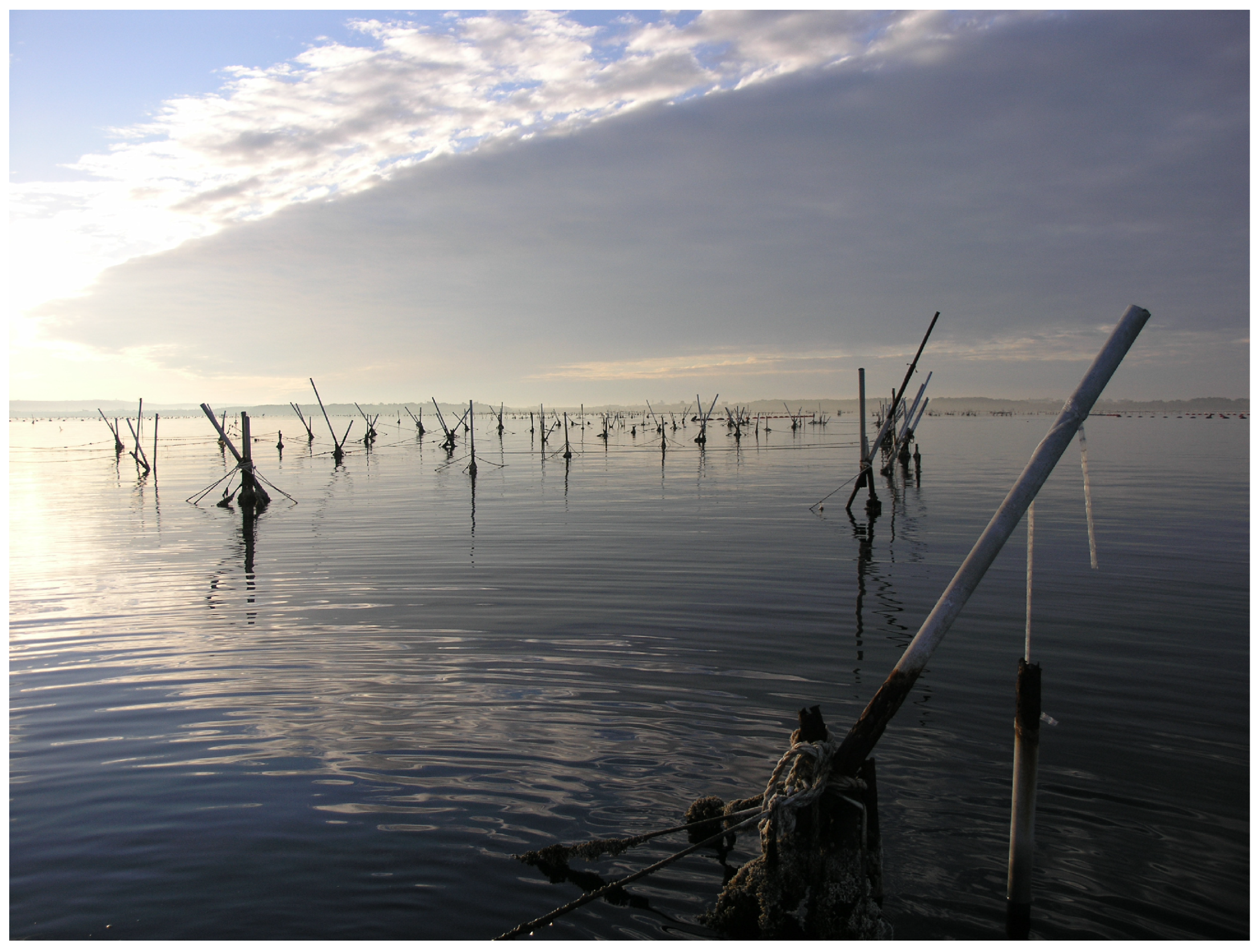
Figure 2 refers, by way of example, to a practical case of possible interaction between jets or jet-like flows and an array of piles belonging to a mussel farming facility.
Despite significant progress, key research gaps remain. The coupling between wave-induced unsteadiness and drag-induced momentum loss in obstructed flows is still poorly understood, particularly in three-dimensional and stratified environments. Moreover, systematic experimental validation of the entrainment and detrainment coefficients under combined forcing (waves and obstacles) is still lacking. Addressing these open issues is essential to advance predictive models of pollutant dispersion, energy transfer, and mixing in realistic environmental settings.
Scope and Structure of the Review
Since the present review specifically addresses the interaction of turbulent jets with surface waves and with rigid or vegetated obstacles, the following sections will refer to and build upon the studies previously discussed. In particular, attention is given to the theoretical, experimental, and numerical frameworks that have progressively shaped our current understanding of these coupled flow phenomena.
This review aims to provide a unified synthesis of the theoretical, experimental, and numerical research on turbulent plane jets subjected to oscillatory wave motion and interactions with rigid obstacles or vegetation.
Section 3 presents the governing equations and analytical framework, including the momentum, energy, and moment of momentum balances. Subsequent sections summarise the main theoretical results and their comparison with laboratory and numerical data. The paper concludes with a discussion of current limitations, unresolved challenges, and prospects for future research on turbulent jet dynamics in complex environmental flows.
2. Mathematical Approach of Jets with Airy Waves
The governing relations for the present problem originate from the Navier–Stokes equations. Each physical variable is decomposed into three distinct components: a steady (time-averaged) mean flow, an oscillatory component that represents wave-induced fluctuations, and a turbulent fluctuation component [
41,
42]. Consequently, the instantaneous velocity component
can be expressed as follows:
Here, the operator
denotes the ensemble average, the tilde
identifies wave-induced (oscillatory) fluctuations, the prime
refers to turbulent fluctuations, and the uppercase or overbarred symbols indicate the mean (time-averaged) flow field. For some of the simplifications, readers can refer to Rajaratnam [
4] and Barile et al. [
43].
In this framework,
t denotes time, while
(
;
,
,
) are the Cartesian coordinates. The
x-axis represents the longitudinal direction of the jet, the
y-axis lies perpendicular to it and follows the direction of wave propagation, and the
z-axis is normal to the
plane. The corresponding velocity components are
(streamwise velocity),
(transverse velocity), and
(normal velocity).
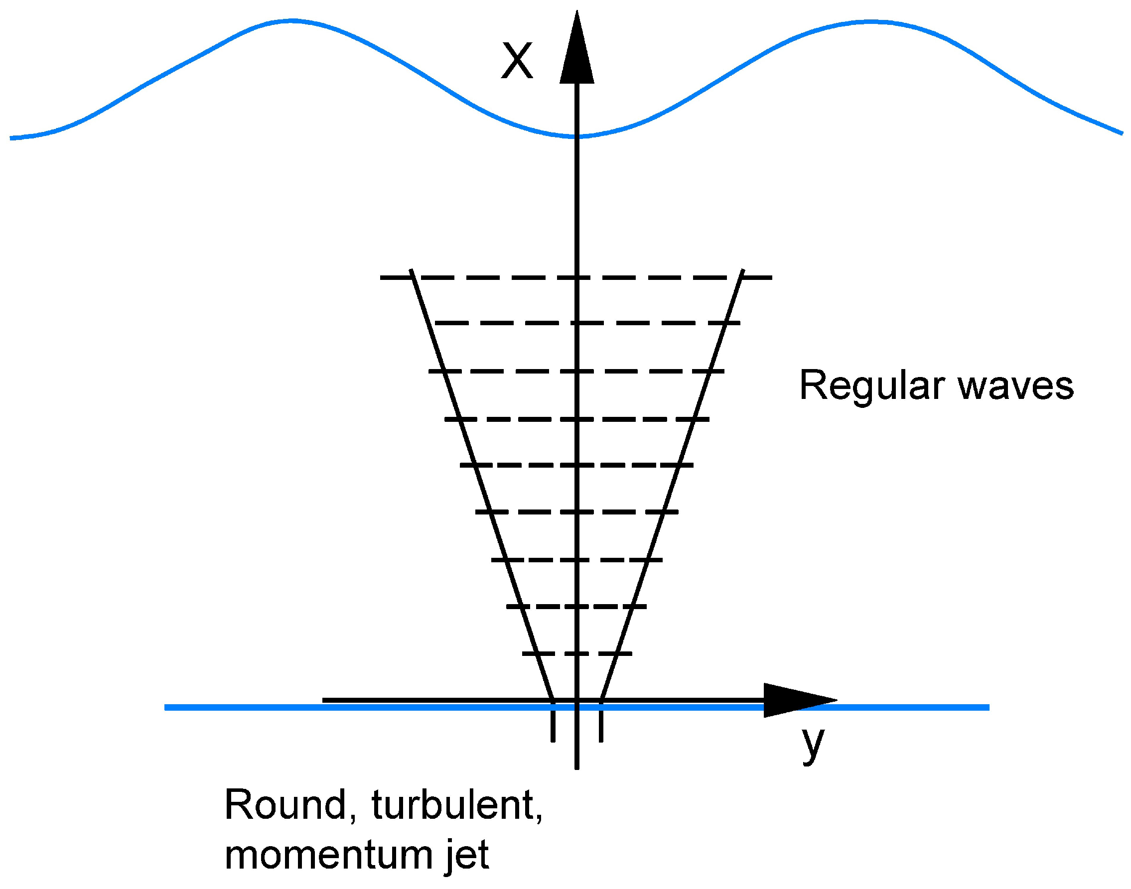
Figure 3 provides a schematic representation of a vertical jet interacting with regular surface waves.
Employing Cartesian tensor notation, the ensemble-averaged form of the momentum equations governing a turbulent jet subject to wave action can be written as follows (see Hussain and Reynolds [
41]):
where
denotes the density of the fluid,
is the Kronecker delta,
p is the pressure, and
represents the dynamic viscosity. The standard properties of time and ensemble averaging yield the following relations:
The analysis is restricted to a two-dimensional (2D) configuration, where the jet propagates along the
x-axis and the wave travels in the
y-direction. Thus, the velocity components can be expressed as follows:
Neglecting molecular viscous stresses and applying averaging and substitution, we have
After averaging over a wave period
T,
Assuming
,
, and
are negligible (see Rajaratnam [
4] and Barile et al. [
43]), we get:
Integrating from
to
,
Differentiating with respect to
x,
Substituting into (
8) and assuming that
is small,
with the turbulent shear stress defined as usual:
2.1. Integral Momentum Equation
The integral momentum equation is obtained by multiplying Equation (
13) by
and integrating in the transverse direction (
y) from 0 to
(where, for each cross-section of the jet,
represents the distance from the jet axis beyond which the influence of the jet can be considered entirely negligible), leading to the following:
Considering that
(due to the symmetry at
and the null shear stress at
from the Airy theory), and using Leibniz’s rule, we obtain
Furthermore, integrating by parts, we obtain
At
, let
and
(symmetry); at
,
and
. Then using continuity and Leibniz rule,
Thus, Equation (
17) simplifies to
From the Airy wave theory, we have
where
H is the wave height,
L the wavelength,
T the wave period,
d the mean water depth,
a a velocity constant, and the other symbols retain their conventional definitions. Then, it is possible to obtain (see Barile et al. [
43] for details):
Assuming
,
This is an interesting first result, as it shows that a pure plane jet in a wave environment does not conserve its momentum, unlike the case of a jet discharged into still water. The analyses conducted so far allow us to perform a scaling assessment of the two principal jet scales:
b, defined as the transverse distance in each cross-section of the jet where
, and
, which represents the maximum longitudinal velocity of the jet in each individual cross-section (see
Figure 4).
Let
. Changing variable
, it follows that
Combining Equations (
26), (
29) and (
30),
2.2. Similarity Analysis of the Equations of Motion
To gain further insight into the exponents
p and
q, the equation of motion (
25) and the continuity equation are examined. Based on experimental evidence and dimensional reasoning, we assume the following:
From Equations (
28) and (
35), the following derivatives are defined:
The terms on the left-hand side of Equation (
25) can be estimated as follows:
This result follows from
and multiplying by
yields Equation (
37). Similarly, we find
From the continuity equation together with Equation (
38), we obtain
Because
, Equation (
40) is verified.
To evaluate the right-hand side of Equation (
25), and using Equation (
35), we obtain
Substituting Equations (
38), (
40) and (
42) into Equation (
25) gives
Multiplying by
yields:
Since
depends solely on
, all terms on the right-hand side must also be independent of
x, that is, each term must scale as
. From Equation (
29), we compute
Similarly,
from which
is deduced. We must note that
must be in a range of
x where its order of magnitude is constant. Substituting into Equation (
46) gives
confirming the result of Equation (
34).
2.3. The Integral Moment of Momentum Equation
An equivalent formulation leading to the same scaling laws can be derived by employing the integral moment of the momentum equation. Multiplying the equation of motion (
25) by
y and integrating between
and
, we obtain
Using the product differentiation rule, the continuity equation and integration by parts, the first integral can be written as
and, similarly,
so that the sum of the two integrals yields
Performing integration by parts on the shear stress term gives
Given that
the final term on the right-hand side of Equation (
48) can be expressed as
Substituting Equations (
51), (
52) and (
54) into the integral moment of momentum Equation (
48), we obtain
Using Equations (
28) and (
41), the integral
can be expressed as
where
and
. Combining Equations (
28), (
36) and (
57), we obtain
After eliminating
and defining
Equation (
57) becomes
From Equation (
29), we derive the following relations:
The first two conditions lead directly to
and
. Moreover, the third condition,
(or equivalently, Equations (
35) and (
47)), is also satisfied for
and
under the following reasoning: We first assume that
which implies
To ensure that the term
remains approximately constant, we consider
, with
, such that
and
have the same order of magnitude:
where
denotes the integer part. Since
, it follows that
and
share the same order of magnitude when
with
, or
with
. Therefore, Equation (
64) is valid when
and
have identical orders of magnitude, that is, when
for
, or
for
.
Consequently, for
with
belonging to these ranges, and considering Equations (
65) and (
66), the condition is fulfilled. Following the same reasoning, by selecting appropriate
intervals, Equations (
34) and (
47) are also verified for
and
.
Finally, the coefficients
and
can only be determined through experimental data. It is reasonable to assume that they vary with the
x-range considered. Consequently, the parameters
,
, and
appearing in Equation (
29) depend on the chosen interval
.
2.4. Dimensional Analysis
Based on the previously derived exponents
and
, and by nondimensionalizing both Equation (
29), they can be reformulated as follows:
where
,
, and
are dimensionless constants that must be determined experimentally.
Applying the Buckingham
theorem, it follows that these coefficients depend on the set of dimensional variables:
Here,
denotes the maximum horizontal oscillatory velocity, which, using Airy’s linear wave theory, can be obtained from Equation (22),
g is the gravitational acceleration and
is the dynamic viscosity of the water. By expressing the variables on the right-hand side of Equation (
69) in dimensionless form, we obtain
The first term, , represents the relative water depth, which identifies three distinct flow regimes:
corresponds to shallow water, where wave-induced velocities are nearly uniform throughout the depth;
defines deep water, characterized by an exponential decay of orbital velocities from the free surface down to a depth of , with ;
denotes intermediate-depth conditions.
The ratio represents the steepness of the wave, while corresponds to the non-dimensional depth parameter under deepwater conditions, in addition to the factor . Both quantities are also commonly used in the Le Méhauté diagram for classifying wave regimes.
The term quantifies the relative importance of wave-induced momentum compared to the initial momentum of the jet at the source. The parameters and are, respectively, the inlet Froude and Reynolds numbers, which characterize the flow’s dynamic and viscous scales.
Hence, the coefficients
,
, and
appearing in Equations (
69) and (
70) must be determined through laboratory experiments or high-fidelity numerical simulations. In the case of a fully turbulent regime, it is reasonable to expect that the Reynolds number will exert negligible influence on their values, leaving only a subset of the dimensionless parameters in Equation (
67) as the dominant factors controlling
b and
.
Finally, empirical relationships for the variation in
,
, and
may further constrain the applicability range of Equations (
69) and (
70), potentially defining narrower validity domains compared to the theoretical limits implied by Equations (
65) and (
66).
2.5. The Integral Energy Equation
Recalling the momentum Equation (
25)
Multiplying Equation (
71) by
and integrating from
to
gives
Introducing the definition of the mean kinetic energy per unit volume,
, one obtains
Hence, the integral balance of energy can be expressed as follows:
By applying the continuity equation and performing integration by parts, we obtain
For the first term on the right-hand side of Equation (
72), integration by parts yields
Thus, the integral form of the energy equation becomes
Using Equations (
28) and (
36), and substituting
, we can express the previous equation as follows:
Simplifying and introducing the following integral coefficients
the resulting expression can be written as follows:
Using the power-law relationships defined in Equation (
29), we obtain
Substituting
, the equation simplifies to
This result confirms and is consistent with the relationships previously obtained in Equations (
34) and (
47), reinforcing the validity of the derived scaling laws for the energy distribution within the jet under wave-induced oscillatory forcing.
Some relevant experimental and numerical results on this topic have been published by [
29,
30,
43,
44,
45,
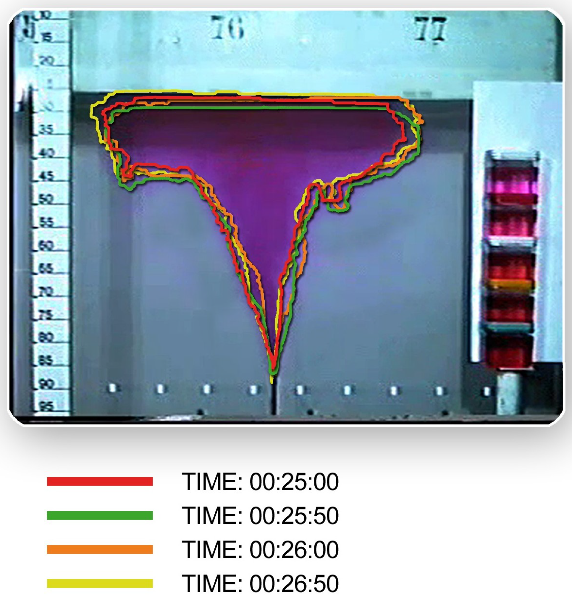
46], to which the reader is referred for further details. Referring to the aforementioned studies,
Figure 5 illustrates the contours of a jet subjected to oscillations induced by wave motion at different phases of the sinusoidal wave reproduced in the laboratory.
The results presented in this review were also corroborated by Large Eddy Simulation (LES) studies reported by [
47].
3. Theoretical Model of a Plane Jet with Rigid Obstructions
Turbulent jets often encounter backgrounds with pronounced structural heterogeneity in environmental and engineering flows [
39]. We examine the benchmark case of a
plane turbulent jet issuing in an unbounded homogeneous fluid of constant density, so that buoyancy effects may be neglected. The jet emerges from an opening located a distance
above a reference level, with a characteristic exit speed
. In the limit of negligible ambient current (
), the evolution follows the classical picture: a potential (or initial) core that extends roughly
downstream, after which the flow transitions to a fully developed self-similar regime.
Within this fully developed zone, the cross-stream profile of the streamwise velocity is well described by a Gaussian distribution:
where
is the centerline velocity and
denotes the half-width such that
at
. This assumption is consistent with canonical similarity theory for turbulent plane jets and constitutes the starting point for the subsequent analysis.
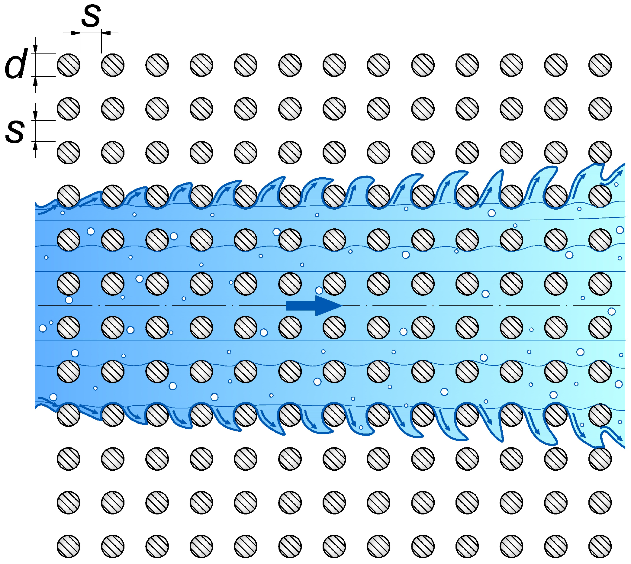
We extend the reference configuration to include interaction with a structured porous layer represented by a periodic array of rigid vertical cylinders, serving as an idealised model of emerging vegetation. This canopy introduces distributed form and viscous drag, thereby mediating momentum exchange with the jet. Each element has diameter d and uniform spacing s along both principal directions, forming a square lattice. The density per unit planform area is , leading to a frontal area per unit volume . It is worth noting that, in the case of jets interacting with stem-like obstacles, the conventional notation has been retained, where d denotes the stem diameter and a the frontal area per unit volume. This choice is made with the understanding that no confusion should arise with the previous case involving wave motion, where these symbols were used with different meanings. The associated solid volume fraction is , and the porosity is .
Flow through such a canopy exhibits pronounced spatial heterogeneity at the obstacle scale and temporal variability due to turbulence and unsteady wakes. A standard approach to incorporate these multiscale effects is the double-averaging framework: one first performs a temporal average over times longer than the turbulent fluctuations, then a spatial average over a representative elementary volume that spans several cylinders but is restricted to the fluid volume. The outcome is a set of macroscopic equations retaining the leading-order effects of drag-induced momentum loss and interfacial transfer.
In the present work, we adopt a time-averaged (RANS) description while preserving spatial variability in both streamwise and transverse directions. This choice is adequate to capture jet entrainment and lateral spreading within the canopy. The impacts of intermittency and spatial variability will be addressed later from a Lagrangian viewpoint, more suitable for describing parcel trajectories and residence times in obstructed regions.
For a plane turbulent jet discharging into a quiescent ambient in the presence of a cylinder array (see
Figure 6), the governing equations reduce to the Reynolds-averaged momentum balances,
In this context,
u,
v, and
w denote the mean velocity components along the
x,
y, and
z axes, while
,
, and
correspond to their respective fluctuating components. The symbol
p indicates the local time-averaged pressure,
is the kinematic viscosity,
stands for the density of both the jet and the surrounding fluid, and
t represents time. Naturally, this formulation must be accompanied by the following continuity continuity Equation (
85):
We consider a regular square array of cylinders of diameter
d and spacing
s (
Figure 6). The drag per unit volume along the three axes, i.e., the combined form and the viscous resistance exerted by the stems, is indicated by
. Following Nepf [
35], multiple drag laws can be postulated for porous-type flows; in vegetated open-channel and atmospheric canopies a quadratic form is commonly adopted:
where
is the bulk drag coefficient of the array. Because the flow is quasi-two-dimensional, we assume
,
, and vanishing cross terms
. Moreover,
u typically dominates
v over most of the cross-section, and transverse gradients exceed streamwise viscous gradients. Under these approximations, the system (
84) simplifies to
Integrating (
88) across the cross-stream direction and interpreting
p as the outer (ambient) pressure yields
and differentiating (
89) produces
It is generally acceptable to assume
because
u greatly exceeds
v across most of the jet and streamwise variations of the
y-integrated lateral drag are comparatively weak (see, e.g., Rajaratnam [
4]). Neglecting the small contribution then gives
Define the laminar and turbulent shear stresses as
In turbulent jets,
dominates
, and the streamwise pressure gradient is usually subleading [
1,
4,
13]. Consequently,
Integrating (
94) across
y gives
which can be rearranged as
Using continuity (
85) leads to the integral momentum balance
With the quadratic drag model
the momentum flux satisfies
whose solution is
Equation (
100) highlights that, unlike a free jet, a plane jet traversing an obstructed domain does not conserve momentum; instead, it decays exponentially with distance due to canopy drag. Proceeding with a similarity analysis by setting
, we posit
and adopt power-law forms for the centerline speed and half-width,
which imply
or, equivalently,
Because
is
x-independent, (
104) reduces to
hence
From dimensional arguments, we further write
Together with (
101) and the shorthand
we obtain
and
Substituting (
110), (
111) and (
113) into (
94) yields
Since
depends only on
, the right-hand side must also be
-dependent alone. Inspection of the first two terms indicates
which requires
and thus
In what follows, we consider jets for which
with
. Equivalently, the ranges
,
,
are consistent with Appendix 1 of Mossa et al. [
40]. Hence,
A change of order of magnitude of
b occurs when
i.e., when
increases by at least one decade. Therefore,
b retains the same order between two streamwise locations
provided
Since
in the present setting, we may write
Accordingly, over any interval
satisfying (
122), (
114) can be approximated as
with the final term effectively constant within the specified bounds. Combining (
115) and (
107) then suggests
Thus, we write the similarity forms
where
marks the streamwise position at which the jet becomes fully developed, and
,
are the corresponding values of
b and
at
. The discharge per unit depth then reads
Here,
is a dimensionless factor that accounts for cross-sectional geometry and the ratio between section-averaged and maximum streamwise velocity. In particular, the volumetric flow across a section can be written as
with
the nominal outer jet boundary (where
u is nearly zero) and
the section-averaged streamwise speed, leading to
Introducing the entrainment coefficient
, one has
where
is the transverse velocity at the nominal jet edge, directed inward for
(entrainment) and outward for
(detrainment). From (
127) it follows that
and therefore
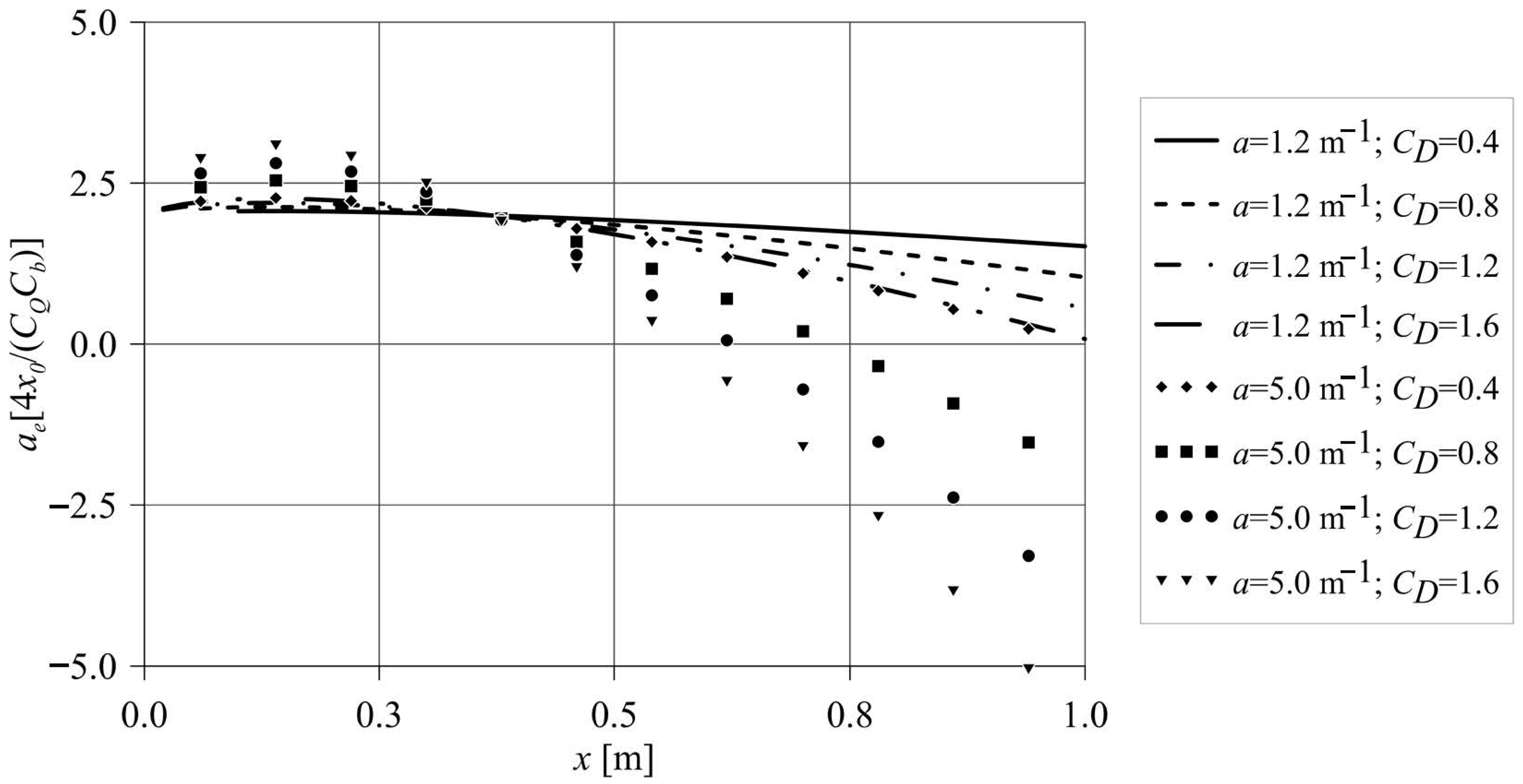
Figure 7 illustrates the predicted evolution of the entrainment/detrainment coefficient as functions of
a and
(with
). Initially, the jet exhibits modest entrainment over a finite streamwise extent; further downstream, the canopy-induced resistance leads to detrainment (
) whose magnitude grows with distance from the nozzle. The suppression of entrainment intensifies with increasing bulk drag
and with larger frontal area density
, reflecting the enhanced momentum extraction by the rigid array. This result was confirmed by [
48], the study of which provides a concise theoretical and experimental examination of turbulent plane jets in obstructed environments. It focuses on how arrays of rigid obstacles alter entrainment dynamics, showing that obstructions suppress entrainment and instead induce detrainment, a behaviour typically associated with buoyant flows. These findings deepen our understanding of flow behaviour in complex environments and have direct relevance for environmental and engineering applications. More complex studies on jet-like flows with obstacles and under the influence of the Coriolis force have been presented by [
49], to which the reader is referred for the sake of brevity.

