Article

Investigation into the Working Behavior of Geotextile Pipe-Bag Systems on Soft Soil Foundations in the Ningde Port Industrial Zone, China

1
Shandong Electric Power Engineering Consulting Institute Co., Ltd., Jinan 250013, China
2
Geotechnical Engineering Department, Nanjing Hydraulic Research Institute, Nanjing 210024, China
*
Author to whom correspondence should be addressed.
Water 2025, 17(21), 3063; https://doi.org/10.3390/w17213063
Submission received: 29 September 2025 / Revised: 23 October 2025 / Accepted: 24 October 2025 / Published: 25 October 2025
(This article belongs to the Special Issue Coastal Engineering and Fluid–Structure Interactions)

Abstract

With the rapid development of coastal and nearshore engineering projects in China, geotextile pipe and bag (GPB) structures have been increasingly applied in marine land reclamation and coastal protection works. To better understand the mechanical behavior of GPB structures on soft soil foundations, this study conducts a systematic investigation into the mechanical properties of both soft soils and GPBs using a physical model test system. By integrating numerical simulations, the stress–deformation characteristics of GPB structures on soft soils and the evolution of pore pressure are further analyzed. The results indicate that the compression curve of soft soil exhibits significant nonlinearity, with silt showing higher apparent compressibility than silty clay. Experimental data yielded the compression coefficient λ and rebound coefficient μ for both soil types. As consolidation pressure increases, deviatoric stress in the soft soil rises notably, demonstrating typical strain-hardening behavior. Based on these findings, the critical state effective stress ratio M was determined for both soil types. The study also establishes the development laws of cohesion c and friction angle φ during soil consolidation, as well as the variation of pore water pressure under different confining pressures. Interface tests clarify the relationships between cohesion and friction angle at the interfaces between geotextile pipe bags and sand, and between adjacent pipe bag layers. Numerical simulations reveal that the reclamation construction process significantly influences structural horizontal displacement. Significant stress concentration occurs at the toe of the slope, while the central portion of the pipe-bag structure experiences maximum tensile stress—still within the material’s allowable stress limit. The installation of drainage boards effectively accelerates pore pressure dissipation, achieving nearly complete consolidation within one year after construction. This research provides a scientific foundation and practical engineering guidance for assessing the overall stability and safety of (GPB) structures on soft soil foundations in coastal regions.

1. Introduction

As a core zone of national economic development and urbanization, China’s coastal regions have faced growing dual pressures from land scarcity and ecological conservation in recent years. In major coastal economic belts—including the Yangtze River Delta, Pearl River Delta, and Bohai Rim—intensive construction of industrial parks, port hubs, and emerging urban areas demands substantial land resources. However, terrestrial space is increasingly saturated, making sea reclamation [1] and tidal flat development [2] critical strategies for alleviating land-use conflicts. These regions are widely underlain by thick deposits of recently formed soft soil, characterized by high water content, low shear strength, high compressibility, and pronounced rheological behavior. Furthermore, these soils are subject to seawater erosion, salinization, and cyclic tidal loading, resulting in highly complex engineering geological conditions. In some offshore reclamation projects, fill construction is carried out directly on untreated soft foundations, often leading to foundation failure. Consequently, accurately predicting soft soil consolidation deformation and consolidation time, while enhancing foundation bearing capacity and effectively minimizing post-construction settlement within a short timeframe, has become an urgent technical challenge in coastal reclamation engineering. For such projects, embankment structures serve as a key technological component—forming the foundational element of project implementation and directly influencing land formation and the safety of subsequent construction activities. Achieving economical, rapid, and safe embankment construction to support efficient hydraulic filling operations continues to face numerous “bottleneck” technical challenges. Therefore, developing new types of cost-effective and structurally reliable embankment systems is essential for advancing sustainable sea reclamation and coastal infrastructure development in China.
Geotextile pipe bag (GPB) technology was first developed and applied in Europe and is widely used in marine engineering structures and shoreline protection projects, such as scour and erosion control, coastal defense systems, and underwater constructions [3,4]. In environmentally sensitive areas—such as wetland restoration, tidal flat management, and shoreline protection—construction techniques are subject to stringent ecological impact requirements abroad, with emphasis on minimizing environmental disturbance during construction. Due to its ease of construction and low environmental footprint, GPB technology is well suited to meet the demands of such projects. The GPB structure [5,6,7] is an embankment system formed by sewing geotextile materials [8,9] into bag-shaped containers, filling them with slurry or mortar via high-pressure pumps, and stacking the dewatered units in successive layers. In practice, most GPB structures are constructed on soft soil foundations. Although these structures exhibit a certain capacity to accommodate foundation deformation, numerous instances of instability and failure have been reported in engineering practice [10,11], indicating that systematic and in-depth understanding of their working behavior and the interaction mechanism with soft soil foundations remains insufficient.
Due to the deep soft soil layers and low bearing capacity in coastal areas, ground improvement of soft soil foundations is a prerequisite for constructing superstructures. The investigation of the mechanical properties and constitutive models of soft soils constitutes one of the core topics in geotechnical engineering. Soft soils are characterized by high water content, high void ratio, low permeability, and low strength, exhibiting significant nonlinearity, elastoplasticity, rheological behavior, and anisotropy [12,13,14]. Under loading, soft soils are prone to large deformations and long-term settlements, with their strength evolving progressively during consolidation, leading to complex mechanical responses that are strongly time-dependent [15,16,17]. To address these characteristics, researchers have developed various constitutive models to more accurately capture the stress–strain behavior of soft soils. Early models such as the linear elastic model [18,19] and the Mohr–Coulomb model [20,21] have been widely used in engineering practice due to their simplicity and computational efficiency, yet they fail to adequately represent plastic deformation and dilatancy in soft soils. The Cam-Clay model [22,23], developed subsequently, incorporated critical state theory and successfully described the compressive hardening and contractive shear behavior of soft soils, establishing itself as a classical elastoplastic constitutive model. Continuous refinement of these models has not only enhanced the understanding of soft soil mechanics but also provided a robust theoretical foundation for soft soil foundation reinforcement, subgrade engineering design, and settlement prediction.
In recent years, scholars such as Zhou et al. [24], Zeng et al. [25], Lan et al. [26] and Singh et al. [27] have conducted systematic research on soft soil foundation treatment techniques and comprehensively summarized the advantages and disadvantages of various methods. These research outcomes have played a significant role in geotechnical engineering and provided robust theoretical support for engineering practices involving soft soil foundations. Overall, a wide range of treatment methods are currently available, primarily including dynamic compaction [28,29], drainage consolidation [30,31], and chemical solidification [32]. In practice, the selection of a single method or a combination of multiple methods is typically based on the physical and mechanical properties of the foundation. A comparative analysis of these technologies indicates that the drainage consolidation method has become the preferred approach for soft soil foundation treatment due to its cost-effectiveness and relatively short construction duration.
As shown above, there is currently a lack of systematic research on the structural behavior of geotextile pipe bags (GPBs) in soft soil foundations in coastal areas. To address this gap, this study innovatively employs an integrated approach combining field monitoring, physical experiments, and numerical simulation to investigate the overall deformation and stability of GPB structures in coastal and nearshore engineering applications. First, a comprehensive analysis was conducted on the physical and mechanical properties of both soft soils and geotextiles in coastal environments. These findings were then integrated with field monitoring data and numerical simulations to systematically examine the operational characteristics of GPB structures on soft soil foundations. The study aims to provide a robust theoretical foundation and technical support for evaluating the stability of soft soil foundation treatment techniques and GPB structural systems.

2. Mechanical Properties of Soft Soil and Geotextiles

2.1. Project Overview

The authors express their gratitude for your insightful suggestions. Based on the construction of a GPB structure on soft soil in the coastal area of Ningde, China, this study examines the engineering characteristics of soft soil, with particular emphasis on the deformation behavior of the soft soil foundation. To this end, a series of experimental investigations were conducted to determine the physical and mechanical properties and key calculation parameters of the soft soil. Specifically, compressive consolidation tests, interface friction tests, direct shear tests, triaxial shear tests, and on-site in situ strength tests were performed on foundation soft soil samples to evaluate critical geotechnical indices, including the compression index, rebound index, shear strength, and stress–strain characteristics. The Ningde Coastal Industrial Zone land reclamation project is situated on the northern side of Niuyu Island. The project is primarily divided into two zones: the startup base and the mining construction materials area. The startup base covers a sea area of 495,200 m2 and a reclaimed land area of 440,400 m2, with a maximum east–west extent of approximately 1150 m and a maximum north–south width of about 810 m. The mining construction materials area utilizes a sea area of 462,700 m2, forming a reclaimed land area of approximately 406,500 m2, with a maximum east–west length of around 650 m and a maximum north–south width of about 900 m. The total revetment length is 1239 m. The layout of the Ningde Land Reclamation Project is illustrated in Figure 1.
To study the deformation and stability characteristics of the upper cofferdam—GPB structure, a monitoring and analysis of the entire construction process of the GPB loading was carried out to provide guidance for on-site construction. This project has a large site area and inconvenient transportation. The monitoring instruments and equipment as well as materials could only be transported to the installation points by manual multiple times. The drilling pile machine was first disassembled, then transported to the installation location by manual, and then reassembled. During high tide, the pile was moved to the designated location according to the design for the settlement plate installation, so as to obtain the initial values in time and ensure the normal operation of the instruments. When the monitoring values exceeded the warning value, an early warning was promptly reported. Regardless of day or night, frequent observations were made and patrols were strengthened to ensure the safety and stability of the GPB structure.
Taking into account the on-site terrain and soil conditions, a total of 13 settlement points (displacement meters), 3 full-section settlement observation points (3 layers of settlement tubes for each section), and 6 pore pressure observation points (each point buried 6 pore pressure meters) were arranged. The layout of the section instruments is shown in Figure 2.

2.2. Test Preparation

It is widely accepted that the modified Cam-Clay model is suitable for characterizing the mechanical behavior of soft soils. The model comprises three material parameters and one state parameter: the critical state effective stress ratio M, the compression index λ, the swelling index κ, and the initial void ratio e0. Among these, M can be determined from consolidated undrained triaxial tests, while λ and κ are typically derived from one-dimensional consolidation-rebound tests. The main physical property indices of the soft soil are summarized in Table 1.
For the standard consolidation-rebound test, the standard specimen, together with the cutting ring, is placed into the consolidometer and subjected to loading and unloading. Loading is applied incrementally in the sequence of 12.5, 25, 50, 100, 200, 400, and 800 kPa. After reaching 800 kPa, unloading is performed in the order of 400 and 200 kPa back to the first load level. The water reservoir should be immediately filled upon application of the first pressure level. The stability criterion at each load stage is defined as a deformation rate not exceeding 0.01 mm per hour. Subsequently, three additional tests were conducted with loading sequences of 20, 40, 80, 150, 200, 320, and 640 kPa, with each load level maintained for 48 h of consolidation.
For the consolidated undrained (CU) triaxial test, two types of soft soil collected from the field were prepared into cylindrical specimens with a diameter of 39.1 mm and a height of 80 mm. Confining pressures were set at 50, 100, 150, 200, and 250 kPa, respectively. The tests were conducted using an automatic triaxial apparatus, with the shear strain rate controlled at 0.02 mm/min. Each test series was repeated three times to ensure data reliability.
In the direct shear friction test, the GPB remains relatively stationary while the sand body undergoes displacement. The GPB experiences passive resistance, resulting in single-sided friction between the bag and the sand. Shear stress develops along the interface where relative sliding occurs. In contrast, during the pull-out friction test, the geogrid is actively pulled out under an applied tensile force, leading to double-sided friction between the geotextile bag and the surrounding soil. Shear stress is distributed across both the upper and lower surfaces of the bag, and the normal stress is determined based on the vertical load applied in the test. Considering the actual stress mechanism, this study adopts the direct shear friction test method to investigate the interface friction behavior between geotextile bags and sand.

2.3. Mechanical Properties of Soft Soil

Through the one-dimensional consolidation-rebound test, the e-lnp curves of the two soil layers under different vertical loads were obtained. As shown in Figure 3, the compression curve of soft soil exhibits distinct nonlinear characteristics, and the apparent compressibility of silt is higher than that of silty clay. Based on the slopes of the compression and rebound curves from the one-dimensional consolidation-rebound test data plotted in the e-lnp plane, the compression indices λ and rebound indices κ for silt and silty clay were determined as λ1 = 0.0646, κ1 = 0.0117, λ2 = 0.0775, and κ2 = 0.0105, respectively.
Three groups of specimens were subjected to consolidated undrained (CU) triaxial tests under confining pressures of 50, 100, 150, 200, and 250 kPa, respectively. The measured relationship between axial strain and deviatoric stress is presented in Figure 4. Results indicate that both silty soil and silty clay exhibit strain-hardening behavior. For silty soil, the deviatoric stress increases continuously with increasing axial strain. For silty clay, the deviatoric stress rises significantly when axial strain is below 3%; however, beyond 3% axial strain, the rate of increase gradually diminishes. In this study, the deviatoric stress at 15% axial strain is adopted as the failure strength, denoted as q. The parameter M represents the ratio of deviatoric stress q to mean effective stress p along the critical state line, i.e., M = q/p. Linear regression of the p and q data points under different confining pressures was performed in the p-q plane (Figure 5), yielding critical state stress ratios of M1 = 0.962 for silty clay and M2 = 0.499 for silt.
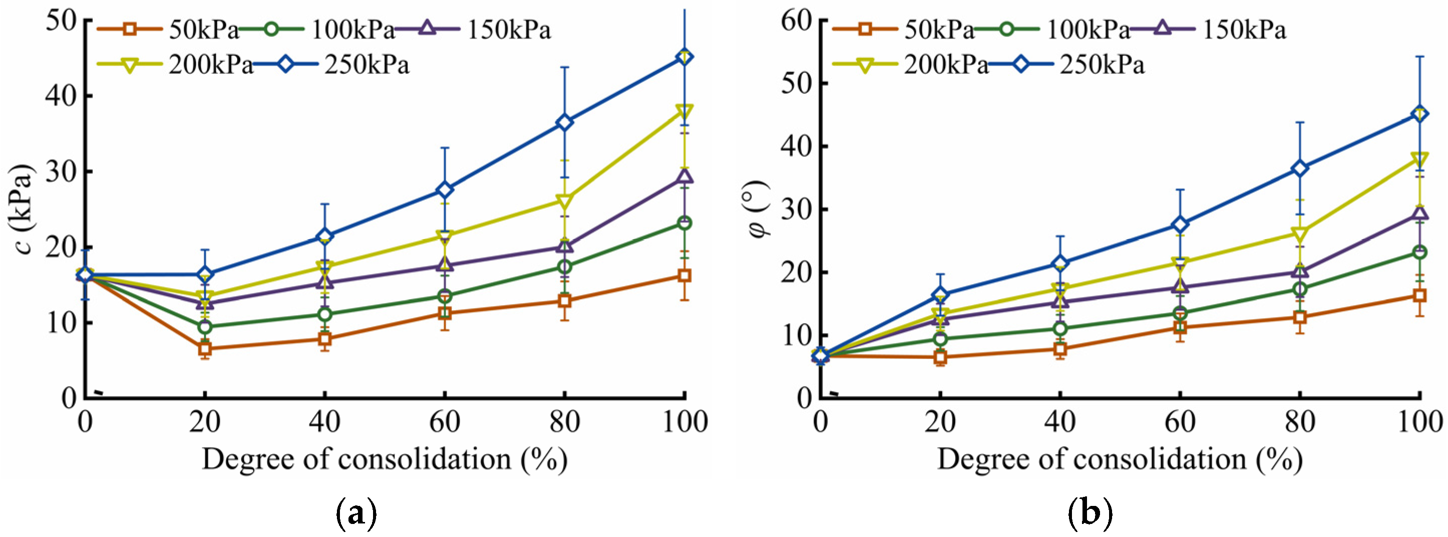
Figure 6 presents the variation of the shear strength parameters of soft soil with initial consolidation degree under different consolidation pressures. The cohesion exhibits a relatively large fluctuation range; when the consolidation degree reaches 100%, its maximum value is approximately three times the minimum value. In contrast, although the friction angle φ varies less than cohesion c, its maximum value still approaches twice the minimum value at 100% consolidation degree. Overall, both c and φ increase with increasing confining pressure and consolidation degree. This trend is primarily attributed to the progressive densification of soil during the drainage consolidation process, wherein interparticle distances decrease and pore volume diminishes, leading to enhanced overall shear strength of the soil mass.
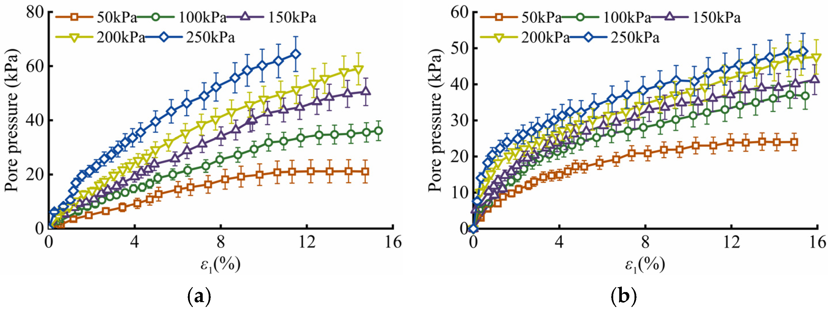
Figure 7 presents the relationship between pore water pressure and axial strain for silt and silty clay under different consolidation pressures. It can be observed that at small axial strains, the pore pressure increases rapidly; as the strain further increases, the rate of increase gradually slows down and eventually reaches a stable value. Meanwhile, pore pressure rises significantly with increasing consolidation pressure. However, with higher consolidation pressure, the ratio of maximum pore pressure to total stress decreases from 36.9% to 27.5% for silt and from 45.5% to 17.8% for silty clay. Both ratios exhibit a decreasing trend with increasing consolidation pressure, indicating that under a consolidation pressure of 250 kPa, the second layer of silty clay possesses a greater capacity to resist deviatoric stress compared to the first layer of silt. This difference in excess pore pressure development may be a primary factor contributing to its ability to sustain higher deviatoric stresses.

2.4. The Mechanical Properties of Geotextiles

Through interface friction tests on GPBs, the relationship between shear stress and shear displacement was obtained. Figure 8a presents the test results for the bag–sand interface. It can be observed that as shear displacement increases, the tangential stress at the interface gradually rises. The rate of increase is relatively high during the initial stage, indicating rapid development of interfacial friction. After reaching peak stress, the growth rate decreases, exhibiting pronounced nonlinear behavior that can be well described by a hyperbolic function. Under higher vertical stress conditions, a slight softening phenomenon occurs, primarily during the later stages of shearing. Figure 8b shows the results for the bag–bag interface, where the stress–displacement curve also displays significant nonlinearity. With increasing vertical stress, the peak shear stress increases, while the corresponding peak shear displacement remains largely unchanged. Moreover, the degree of stress softening is notably greater than that observed in the bag–sand group.
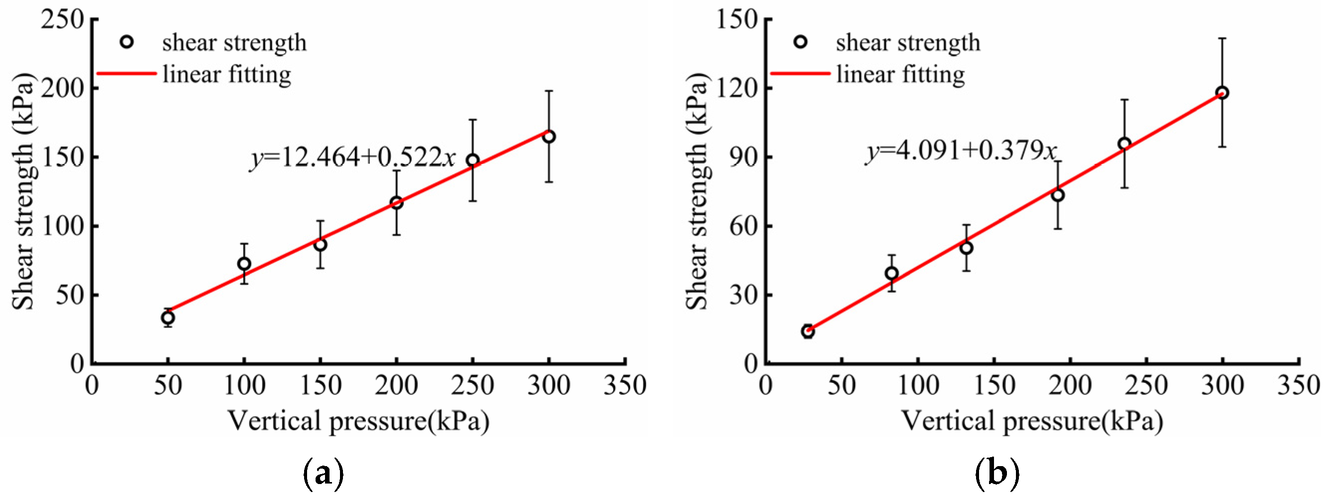
Figure 9 illustrates the relationship between the shear strength of geotextile bags and vertical pressure. The results show that the peak shear strength τ of the bag–sand interface exhibits a strong linear correlation with normal stress σn, consistent with the Mohr–Coulomb strength criterion: τ = cgs + σn tanφgs. The fitted interface cohesion cgs is 6.90 kPa, and the friction angle φgs is 27.3°. For the bag–bag interface, the shear strength also follows this linear model, but with no cohesive component, and a friction angle φgs of 21.6°.

3. Finite Element Modeling of Geotextile Pipe-Bag Structures

3.1. Constitutive Models

The Mohr–Coulomb model is widely used in finite element analysis. In an ideal elastoplastic material, only elastic deformation occurs before the stress reaches the yield point. Once yielding begins, irreversible plastic deformation takes place and continues until material failure. The yield surface morphology is shown in Figure 10.
The yield surface function of the Mohr–Coulomb model is defined by Equation (1):
f = 1 2 σ 1 σ 3 1 2 σ 1 + σ 3 sin φ c cos φ
where c is the cohesion of the material, while φ denotes the inclination angle of the Mohr–Coulomb yield surface, which corresponds to the internal friction angle.
The Cam-clay model is an elastoplastic constitutive model developed by Roscoe and colleagues at the University of Cambridge, UK. Based on experimental observations, it employs an elliptical yield surface and an associated flow rule (Figure 11). The model features a simple set of parameters that are relatively easy to determine, contributing to its widespread application in geotechnical engineering both domestically and internationally. It is particularly applicable to normally consolidated soils and lightly overconsolidated clays. The mathematical expression of its yield surface is:
f = λ κ 1 + e 0 ln p p 0 + λ κ 1 + e 0 1 M q p ε v p = 0
Subsequently, modifications were introduced to the yield surface, leading to the development of the modified Cam-clay:
f = λ κ 1 + e 0 ln p p 0 + λ κ 1 + e 0 ln 1 + q 2 M 2 p 2 ε v p = 0
where M denotes the critical state stress ratio, and e0 represents the initial void ratio, defined as the void ratio of soft soil corresponding to an initial mean effective stress p0 = 0. λ is the slope of the normal compression line (NCL), while κ is the slope of the unloading-reloading line and serves as the hardening parameter, representing the plastic volumetric strain. The simulation results presented in Figure 12 demonstrate that the modified Cam-Clay model more accurately captures the mechanical behavior of soft soil than the original Cam-Clay model.

3.2. Parameters of Constitutive Models

The Mohr–Coulomb model is widely used in finite element analysis. In an ideal elastoplastic material, only elastic deformation occurs before the stress reaches the yield point. Once yielding begins, irreversible plastic deformation takes place and continues until material failure. The modified Cam-Clay model was adopted to simulate the soft soil foundation, while the Mohr–Coulomb model was used for the fill sand material. The parameters for the fill sand are listed in Table 2, and those for the soft soil are provided in Table 3. Geotextile bags were modeled as membrane elements. The interactions between geotextile bags, as well as between geotextile bags and the soft soil foundation, were simulated using surface-to-surface contact pairs. Based on interface friction tests, the cohesion c at the bag–sand interface is 6.89 kPa, with a friction coefficient μ of 0.51; the friction coefficient μ at the bag–bag interface is 0.39; and the friction coefficient μ at the bag–soft soil foundation interface is 0.27.

3.3. FEM Model

This study employs ABAQUS 6.14 software to establish a three-dimensional finite element model consisting of 258,603 nodes and 235,969 elements. GPBs are modeled as reinforcement within the sandy embankment fill. Although numerous studies have investigated the soil-reinforcement interface interaction, the multiplicity of influencing factors has prevented the establishment of a universally accepted simulation approach. Given that geotextile bags can resist tensile forces but not compressive ones, the membrane element (M3D4R) available in ABAQUS is used to simulate their reinforcing behavior. Interactions between bags and between the bags and the underlying soft soil foundation are all modeled using surface-to-surface contact formulations. The overall soil domain is discretized using C3D8P pore-pressure solid elements, while the geotextile bags are represented by M3D4R membrane elements. The foundation comprises 28 m of soft soil overlying 12 m of bedrock. Plastic drainage boards are incorporated into the soft soil layer with a penetration depth of 28 m. At the base of the cofferdam, a 1 m thick medium-coarse sand cushion is implemented, constructed in two 0.5 m layers. A total of 13 layers of geotextile bags are simulated, each with a thickness of 0.5 m. The interface between the foundation and the lowest GPB is defined as a zero pore-pressure boundary. To minimize boundary effects on displacement in the reinforced zone, lateral boundaries of the model were extended sufficiently during computation. Three-directional displacement constraints are applied at the base of the bedrock, and a staged loading procedure is adopted to simulate the sequential filling process at the construction site. The detailed configuration of the numerical model is presented in Figure 13.

4. Working Behavior of Geotextile Pipe-Bag Structures

4.1. Displacement Deformation Characteristics

Figure 14 presents the settlement distribution contour map of the geotextile pipe-bag structure. It can be observed that during the filling stage, deformation of the cofferdam and foundation is dominated by vertical settlement, with a maximum value of approximately 0.13 m. Slight uplift occurs at the toe of the cofferdam slope, while a “U”-shaped settlement profile develops at the structural center. Concurrently, the settlement at the slope toe exhibits an outward-diffusing pattern. After the installation of the geotextile tube bags (GPBs), a 30-day construction break is implemented, during which the structure undergoes static drainage consolidation. Under the influence of the plastic drainage boards, the extent of the high-settlement zone slightly decreases, with the maximum settlement occurring near the central axis of the cofferdam. The bottom of the GPB structure was selected as the monitoring location. Upon completion of filling and commencement of construction of the mortared stone retaining wall and surface and base protection structures, the settlement increased to approximately 1.26 m. Following the completion of land reclamation via sand filling, the settlement further increased to 1.71 m. After construction ended, the structure was continuously monitored for one year. Calculations indicate that the post-construction settlement after one year reached 2.43 m. The computed settlement values show good agreement with the field monitoring data.
Figure 15 presents the horizontal displacement contour map of the GPB structure. It can be observed that when the filling elevation reaches 0.5 m, the maximum horizontal displacement is approximately 0.027 m, with a nearly symmetrical distribution on both sides, indicating a relatively stable structural behavior. During the construction interval, the drainage plates gradually exert their drainage and consolidation function, leading to a slight reduction in horizontal displacement; however, this reduction is considerably smaller than that observed in vertical displacement. During the reclamation process, horizontal displacement begins to increase at a relatively rapid rate. This phenomenon is primarily attributed to the low permeability of the foundation silt, short construction intervals, and the ongoing consolidation of the foundation, which collectively induce a pronounced sudden increase in deformation during continued filling of the enclosure structure. Upon completion of all land reclamation by sand filling, the horizontal displacement reaches 0.337 m. One year after the completion of reclamation, the horizontal displacement slowly increases to 0.433 m, with the computed results showing good agreement with the field measurement data.
Figure 16 presents the consolidation settlement curves at the left side, center point, and right side of the GPB structure base. As depicted in Figure 16, the settlement curve at the left-side measurement point of the soft soil foundation exhibits an upward trend for a period after 180 days. This phenomenon is attributed to lateral earth pressure inducing compression that causes uplift of the settlement plate. At the same time points, the settlement values at all measurement points are reduced compared to earlier stages, whereas the final settlement at the center point of the enclosure structure base remains essentially unchanged relative to the original value. These observations indicate that the installation of plastic drainage boards can effectively accelerate the drainage rate of the foundation, facilitate earlier completion of drainage consolidation in soft soil foundations, and thereby significantly shorten the construction duration of the upper GPB structure.

4.2. Stress Characteristics

Figure 17 presents the first principal stress cloud diagram of the GPB structure. It can be observed that during the filling stage, the overall structure is predominantly under compressive stress, with stress at the slope toe increasing gradually. By the 150th day of construction, the main structural filling is essentially complete, and the compressive stress distribution exhibits an upward trend. This phenomenon may be attributed to localized stress disturbance induced by drainage from the installed drainage boards. Upon completion of reclamation, the overall compressive stress in the structure decreases, while significant tensile stress concentration develops at the slope toe, with maximum tensile and compressive stresses reaching 0.59 MPa and 3.23 MPa, respectively. One year after construction completion, as excess pore water pressure dissipates, the magnitude of tensile stress gradually diminishes.
Figure 18 presents the third principal stress cloud diagram of the GPB structure. Overall, during the filling process, the third principal stress is predominantly compressive. When structural filling is completed, stress concentration at the slope toe becomes clearly evident. The dissipation of excess pore water pressure leads to a reduction in the magnitude of the third principal stress within the structure. Throughout the backfilling process, the internal stress in the geotextile tube bag (GPB) remains entirely compressive. As backfilling progresses, the entire structure experiences an increasingly pronounced state of compression. After one year of pore pressure dissipation, the maximum compressive stress decreases by approximately 17%.
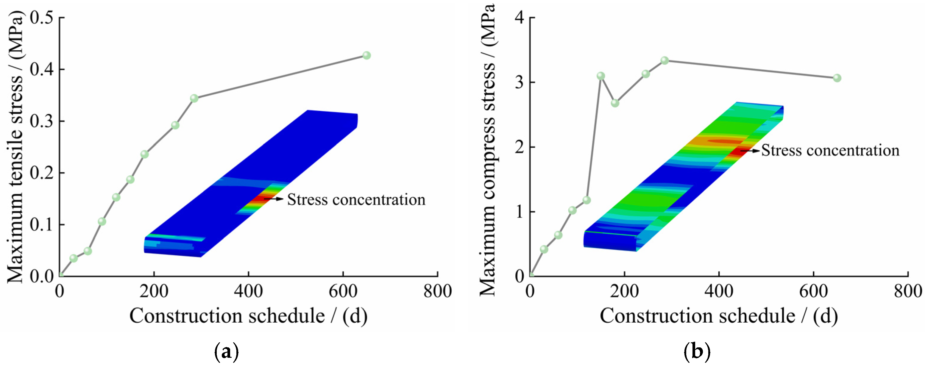
Based on the previous force analysis of the GPB structure, it is evident that the bottom layer experiences the most significant stress. Therefore, the geotextile bag at the bottom layer is selected for further stress analysis. Figure 19 illustrates the evolution of stress distribution in the bottom geotextile pipe bag. During construction, a distinct tensile stress concentration develops at the bottom of the pipe bag. As construction progresses, both the overall tensile stress and the peak compressive stress increase progressively. One year after construction completion, the maximum tensile stress increases slightly, while the peak compressive stress decreases moderately; however, neither exceeds the allowable stress range.
Figure 20 presents the pore water pressure cloud map of the GPB structure. At 30 days into construction, the pore water pressure exhibited an upward trend. On the foundation surface near the structure, the presence of drainage boards led to a significant reduction in pore water pressure. The monitoring point was located 2 m below the base slab of the GPB structure. It can be observed that prior to completion of filling, the dissipation rate of pore pressure was considerably lower than its generation rate. During the hydraulic filling process, pore pressure began to show signs of dissipation. One year after construction completion, pore pressure dissipation became evident, and the pressure at the monitoring point turned negative, indicating that the drainage boards effectively promote the dissipation of pore pressure.

5. Conclusions

This study innovatively integrates multiple research methodologies—namely, on-site monitoring, physical experiments, and numerical analysis—to systematically investigate the working behavior of geotextile pipe bag (GPB) structures on soft soil foundations in coastal areas. The mechanical properties of soft soil foundations were systematically evaluated through laboratory-based physical experiments. Subsequently, by integrating field monitoring data with numerical simulations, a comprehensive analysis was conducted on the operational characteristics of GPB structures under coastal soft soil conditions. The main research findings are summarized as follows:
(1)
The compression curve of soft soil exhibits significant nonlinear characteristics, with the apparent compressibility of silt being higher than that of silty clay. The compression and rebound coefficients of soft soil were determined from experimental data. As consolidation pressure increases, the deviatoric stress of soft soil rises significantly, demonstrating typical strain-hardening behavior. Based on these results, the effective stress ratio M for both types of soft soil was derived. A quantitative relationship between shear strength parameters c and φ and the degree of consolidation was established, and the evolution pattern of pore pressure was summarized. Interface characteristic tests were conducted to obtain the c and φ at the interfaces between bags and sand, as well as between adjacent bags.
(2)
A three-dimensional refined numerical model of the GPB structure was developed. Simulation results indicate that foundation settlement progressively increases with construction advancement. During construction breaks, the drainage boards facilitate drainage, effectively reducing the settlement rate. Horizontal displacement is highly influenced by the hydraulic filling process; when the upper fill is asymmetrically placed, uneven horizontal displacements occur across the foundation.
(3)
As hydraulic filling proceeds, the overall structure gradually transitions into a more pronounced tensile state, with stress concentration at the slope toe becoming increasingly evident. One year after completion of filling, tensile stress slightly decreases. The GPB structure remains under tension throughout, with the maximum tensile stress occurring in the central region. However, all peak tensile stresses remain below the material’s allowable stress limit. Drainage boards effectively accelerate pore pressure dissipation, which is nearly complete within one year after construction ends.
The findings of this study provide a scientific basis and practical engineering reference for analyzing the mechanical behavior of soft soil foundations in coastal regions and evaluating the overall stability of overlying GPB structures.

Author Contributions

Conceptualization, P.F. and H.R.; methodology, X.Z.; software, W.L.; validation, W.G., H.R. and P.F.; formal analysis, P.F.; investigation, X.Z.; resources, H.R.; data curation, W.L.; writing—original draft preparation, H.R. and W.G.; writing—review and editing, P.F.; visualization, H.R.; supervision, X.Z.; project administration, P.F.; funding acquisition, W.L. All authors have read and agreed to the published version of the manuscript.

Funding

This research was funded by an independent research project of Shandong Electric Power Engineering Consulting Institute Co., Ltd., grant number htps202401020; Special Fund for Public Welfare Industry Research of the Ministry of Water Resources, grant number 201401006; Key Projects of the Special Fund for Basic Research Operations of Central-Level Public Welfare Research Institutes, grant number Y315016.

Data Availability Statement

The raw data supporting the conclusions of this article will be made available by the authors on request.

Acknowledgments

The authors sincerely appreciate the anonymous reviewer and editors’ valuable comments and suggestions to improve the manuscript.

Conflicts of Interest

Author Peijun Fan & Xiatao Zhang was employed by the company Shandong Electric Power Engineering Consulting Institute Co., Ltd. The remaining authors declare that the research was conducted in the absence of any commercial or financial relationships that could be construed as a potential conflict of interest. The authors declare that this study received funding from Shandong Electric Power Engineering Consulting Institute Co., Ltd. (grant number htps202401020). The funder was not involved in the study design, collection, analysis, interpretation of data, the writing of this article or the decision to submit it for publication.

References

  1. Xiong, W.; Luo, Y.; Shangguan, W.G.; Deng, Y.; Xiao, R. Co-hydrothermal carbonization of lignocellulosic biomass and swine manure: Optimal parameters for enhanced nutrient reclamation, carbon sequestration, and heavy metals passivation. Waste Manag. 2024, 190, 174–185. [Google Scholar] [CrossRef]
  2. Hagger, V.; Stewart-Sinclair, P.; Rossini, R.A.; Adame, M.F.; Lovelock, C.E. Lessons learned on the feasibility of coastal wetland restoration for blue carbon and co-benefits in Australia. J. Environ. Manag. 2024, 369, 122287. [Google Scholar] [CrossRef] [PubMed]
  3. Liu, A.S.; Li, W.; Kwok, C.Y. Seawater effects on ground granulated blast furnace slag (GGBS)-stabilized marine deposits in land reclamation. Acta. Geotech. 2025, 37, 397–412. [Google Scholar] [CrossRef]
  4. Bradford, T.E.; Lo, C.C.; Astudillo, J.C.; Leung, R.W.; Lai, C.; Minuti, J.J.; Wong, C.K. Turning riprap into reefs: Integrating oyster shells into shoreline armouring. Mar. Pollut. Bull. 2025, 216, 117933. [Google Scholar] [CrossRef] [PubMed]
  5. Wei, G.; Chu, J.; Yan, S.W.; He, Z.B. Analytical solutions for geosynthetic tube resting on rigid foundation. Geotext. Geomembr. 2014, 6, 65–77. [Google Scholar]
  6. Wei, G.; Chu, J.; Nie, W. Analysis of geosynthetic tubes inflated by liquid and consolidated soil. Geotext. Geomembr. 2014, 42, 277–283. [Google Scholar]
  7. Wei, G.; Chu, J.; Yan, S.W. Simplified analytical solution for geosynthetic tube resting on deformable foundation soil. Geotext. Geomembr. 2015, 43, 432–439. [Google Scholar]
  8. Carneiro, J.R.; Almeida, F.; Carvalho, F.; Lopes, M. Tensile and tearing properties of a geocomposite mechanically damaged by repeated loading and abrasion. Materials 2023, 16, 7047. [Google Scholar] [CrossRef]
  9. Chmura, D.; Salachna, A.; Broda, J.; Katarzyna, K.M.; Gawłowski, A.; Rom, M. Multifunctional geotextiles produced from reclaimed fibres and their role in ecological engineering. Materials 2022, 15, 7957. [Google Scholar] [CrossRef]
  10. Thompsona, A.; Oberhagemannb, K. Yuntong She Geobag stability for riverbank erosion protection structures: Physical model study. Geotext. Geomembr. 2020, 48, 110–119. [Google Scholar] [CrossRef]
  11. Guin, S.; Bhattacherjee, D. Applicability of Geobags as a Sustainable Riverbank Protection Measure. Indian. Geotech. J. 2024, 54, 800–813. [Google Scholar] [CrossRef]
  12. Ying, Z.; Cui, Y.J.; Benahmed, N.; Duc, M. Changes in microstructure and water retention property of a lime-treated saline soil during curing. Acta Geotech. 2022, 17, 319–326. [Google Scholar] [CrossRef]
  13. Lei, H.Y.; Li, C.Y.; Liu, J.J. Experimental study and numerical simulation of an alternating vacuum preloading method for strengthening hydraulic fill super soft soils. Chin. J. Rock Mech. Eng. 2019, 38, 2112–2125. (In Chinese) [Google Scholar]
  14. Cai, Y.Q.; Chen, Y.; Cao, Z.G.; Ren, C. A combined method to predict the long-term settlements of roads on soft soil under cyclic traffic loadings. Acta. Geotech. 2018, 5, 1215–1226. [Google Scholar] [CrossRef]
  15. Jiang, X.; Huang, Z.; Ma, F.; Luo, X. Analysis of strength development and soil-water characteristics of rice husk ash-lime stabilized soft soil. Materials 2019, 12, 3873. [Google Scholar] [CrossRef]
  16. Chen, L.; Lin, D.F. Stabilization treatment of soft subgrade soil by sewage sludge ash and cement. J. Hazard. Mater. 2009, 162, 321–327. [Google Scholar] [CrossRef]
  17. Nanda, R.P.; Priya, N.; Kumar, A. Enhancement of strength of soft soil utilizing construction and demolition wastes reinforced with Recron-3s fibres. J. Clean. Prod. 2025, 505, 145442. [Google Scholar] [CrossRef]
  18. Liu, R.; Yan, H.; Liang, C. A unified lateral soil reaction model for monopiles in soft clay. Ocean Eng. 2025, 319, 120268. [Google Scholar] [CrossRef]
  19. Yang, Y.; Zhou, X.; Zhou, M.; Zhang, X. The behavior of ball penetrometer in soft-over-stiff soil deposits. Ocean Eng. 2023, 273, 114011. [Google Scholar] [CrossRef]
  20. Ye, R.R.; Huang, Z.Y.; Yang, Z.X.; Guo, N.; Jardine, R.; Fu, S. Large deformation analysis of intermittent pile penetration into dense sand incorporating a state-dependent Mohr–Coulomb model. Can. Geotech. J. 2025, 62, 463–472. [Google Scholar] [CrossRef]
  21. Wang, X.; Han, Y.H.; Chen, S.L.; Abousleiman, Y. An analytical drained solution based on graphical method for wellbore drilling problem in dilatant Mohr-Coulomb rock formations. Int. J. Rock Mech. Min. 2025, 193, 106170. [Google Scholar] [CrossRef]
  22. Moeineddin, A.; Platen, J.; Kaliske, M. Constitutive description of snow at finite strains by the modified cam-clay model and an implicit gradient damage formulation. Int. J. Numer. Meth. Eng. 2024, 125, e7595. [Google Scholar] [CrossRef]
  23. Wang, X.; Silbermann, C.B.; Nagel, T.; Nackenhorst, T. Modelling of the elastoplastic behaviour of the bio-cemented soils using an extended Modified Cam Clay model. J. Rock Mech. Geotech. 2024, 16, 2184–2197. [Google Scholar] [CrossRef]
  24. Zhou, Y.; Wang, P.; Shi, L.; Cai, Y.Q.; Wang, J. Analytical solution on vacuum consolidation of dredged slurry considering clogging effect. Geotext. Geomembr. 2021, 49, 842–851. [Google Scholar] [CrossRef]
  25. Zeng, L.L.; Cai, Y.Q.; Cui, Y.J.; Hong, Z.S. Hydraulic conductivity of reconstituted clays based on intrinsic compression. Géotechnique 2020, 70, 268–275. [Google Scholar] [CrossRef]
  26. Lan, P.; Su, J.J.; Ma, X.Y.; Zhang, S. Application of improved physics-informed neural networks for nonlinear consolidation problems with continuous drainage boundary conditions. Acta. Geotech. 2024, 19, 495–508. [Google Scholar] [CrossRef]
  27. Singh, A.; Chakraborty, M. Combined effect of non-darcian flow and semipermeable drainage boundaries on one-dimensional consolidation of unsaturated soil. Int. J. Geomech. 2024, 24, 04024157. [Google Scholar] [CrossRef]
  28. Cai, Y.Q. Consolidation mechanism of vacuum preloading for dredged slurry and anti-clogging method for drains. Chin. J. Geo. Eng. 2021, 43, 201–225. (In Chinese) [Google Scholar]
  29. Ye, G.B.; Xu, Y.; Zhang, Z. Performance Evaluation of PVD-Reinforced Soft Soil with Surcharge and Vacuum Preloading. Int. J. Civ. Eng. 2018, 16, 421–433. [Google Scholar] [CrossRef]
  30. Lim, B.S.; Tumay, M.T.; Lee, J.W.; Chun, B.S.; Jung, J.W. A case study in evaluating the status of consolidation of a soft soil deposit by incomplete piezocone dissipation tests using laboratory and field data. Soils Found. 2014, 54, 648–656. [Google Scholar] [CrossRef]
  31. Yang, S.P.; Yang, A.W.; Xu, A.J. Vacuum preloading reinforcement of soft dredger soil by modified fiber drainage plate. Rock Soil Mech. 2025, 46, 789–797. (In Chinese) [Google Scholar]
  32. Zhou, Y.; Chai, J.C. Equivalent ‘smear’ effect due to nonuniform consolidation surrounding a PVD. Géotechnique 2017, 67, 410–419. [Google Scholar] [CrossRef]
Figure 1. Layout plan of Ningde reclamation project.
Water 17 03063 g001
Figure 2. On-site monitoring instrument layout diagram.
Water 17 03063 g002
Figure 3. Compressive rebound curves of soft soil. (a) silt. (b) silty clay.
Water 17 03063 g003
Figure 4. Soft soil undrained consolidation stress–strain curve. (a) Silt. (b) Silty clay.
Water 17 03063 g004
Figure 5. Linear fitting of effective stress ratio M in critical state.
Water 17 03063 g005
Figure 6. The evolution law of strength parameters of soft soil with the degree of consolidation. (a) c. (b) φ.
Water 17 03063 g006
Figure 7. Pore pressure in soft soil. (a) Silt. (b) Silty clay.
Water 17 03063 g007
Figure 8. The relationship curve between the shear stress and shear displacement of the geotextile bag. (a) Bag–soil. (b) Bag–bag.
Water 17 03063 g008
Figure 9. The relationship curve between the shear strength of geotextile bags and vertical pressure. (a) c. (b) φ.
Water 17 03063 g009
Figure 10. Mohr–Coulomb model. (a) Principal stress space. (b) π plane.
Water 17 03063 g010
Figure 11. Cam-clay model and modified Cam-clay model.
Water 17 03063 g011
Figure 12. Comparison of simulation results between the Cam-Clay model and the modified Cam- Clay model for the CU triaxial test. (a) Silt. (b) Silty clay.
Water 17 03063 g012
Figure 13. Finite element model of geotechnical bag structure on soft soil foundation.
Water 17 03063 g013
Figure 14. The settlement of the geotextile bag structure during the construction period.
Water 17 03063 g014
Figure 15. The horizontal displacement of the geotextile bag structure during the construction period.
Water 17 03063 g015
Figure 16. The settlement curve of the foundation consolidation for the geotextile bag structure. (a) Left. (b) Middle. (c) Right.
Water 17 03063 g016
Figure 17. The tensile stress of the geotextile bag structure during the construction period.
Water 17 03063 g017
Figure 18. The compressive stress of the geotextile bag structure during the construction period.
Water 17 03063 g018
Figure 19. Evolutionary law of stress distribution of the bottom geotextile bag. (a) Tensile stress. (b) Compress stress.
Water 17 03063 g019
Figure 20. The pore pressure of the geotextile bag structure during the construction period.
Water 17 03063 g020
Table 1. The basic mechanical parameters of soft soil.
Soft SoilMoisture Content
w (%)
Unit Weight
γ (kN·m−3)
Void Ratio
e
Liquid Limit
WL (%)
Plastic Limit
Wp (%)
Silt49.317.40.94141.923.6
Silty clay41.918.30.78740.022.7
Table 2. Physical and mechanical index.
γ/(kN/m) c/(kPa) φ/(°)E/(MPa)υPermeability Coefficient k/(m/s)
Silt19032300.36.0 × 10−5
Silty clay 185000.32.0 × 10−4
Table 3. Parameters of soil layers.
SoilυλκMe0Permeability Coefficient k/(m/s)
dredger fill0.430.05930.02140.5431.1252.6 × 10−5
Silt0.410.06460.01170.9620.9411.9 × 10−9
Silty clay0.330.07750.01050.4990.7875.0 × 10−8
Disclaimer/Publisher’s Note: The statements, opinions and data contained in all publications are solely those of the individual author(s) and contributor(s) and not of MDPI and/or the editor(s). MDPI and/or the editor(s) disclaim responsibility for any injury to people or property resulting from any ideas, methods, instructions or products referred to in the content.