Article

Experimental Study on the Motion Response Characteristics of a Floating Wind Turbine with a Semi-Submersible Foundation

1
State Key Laboratory of Hydraulic Engineering Intelligent Construction and Operation, Tianjin University, Tianjin 300350, China
2
Key Laboratory of Earthquake Engineering Simulation and Seismic Resilience of China Earthquake Administration, Tianjin University, Tianjin 300350, China
3
Transport Planning and Research Institute, Ministry of Transport, Beijing 100028, China
4
Research Institute of Tsinghua University in Shenzhen, Shenzhen 518057, China
*
Author to whom correspondence should be addressed.
Water 2025, 17(10), 1501; https://doi.org/10.3390/w17101501
Submission received: 9 April 2025 / Revised: 9 May 2025 / Accepted: 13 May 2025 / Published: 16 May 2025
(This article belongs to the Special Issue Wave–Structure Interaction in Coastal and Ocean Engineering)

Abstract

:
In this study, a series of physical model tests were conducted in a three-dimensional wave basin to examine the motion response characteristics and stability of a floating wind turbine with a semi-submersible foundation with four columns under various conditions, including waves, combined wind and waves, and combined wind, current, and waves. The pitch response amplitude of the floating wind turbine was systematically analyzed to assess the performance of the semi-submersible foundation. The results indicate that utilizing three mooring lines affixed to the three surrounding columns, as opposed to a single mooring line attached to the central column, markedly decreases the pitch response amplitude of the floating wind turbine. Under wind-only conditions, the turbine maintains a stable inclination with a minimal degree of deviation, even when subjected to the maximum design wind load. Across the investigated range of wave periods, the pitch response amplitude shows a rising trend without reaching a peak, suggesting that the natural period of the floating wind turbine is designed to differ from the most prevalent wave periods in real ocean environments. When wave and wind loads are combined, the pitch response amplitude of the floating wind turbine is slightly reduced compared to the amplitude induced by wave load alone. This reduction is likely attributable to the increased spring constant of the mooring lines, resulting from the steady drift under wind. When wave, current, and wind loads are combined, the pitch response amplitude of a floating wind turbine closely aligns with that induced by waves only. This phenomenon occurs predominantly because the current load counterbalances the wind load relative to the center of inertia in terms of pitch response. Furthermore, the combined effect of wind and current induces a steady drift, which subsequently increases the tension in the mooring lines.

1. Introduction

In remote deep-sea regions distant from the mainland, there exists a substantial potential for the development and utilization of high-quality wind resources. To harness these resources through the establishment of offshore wind farms in these sea areas, floating-type foundations are frequently employed. Among these, the semi-submersible foundation represents a prevalent choice for supporting offshore wind turbines [1,2,3]. Currently, numerous countries are vigorously pursuing advancements in the development of foundations for offshore floating wind turbines, with a particular emphasis on semi-submersible designs. Significant progress has been achieved in the conceptual design phase, as well as in research concerning the stability and hydrodynamic performance of these structures [4,5,6].
There have been a few studies on the concept design and stability standard of floating foundations for the wind turbine. According to Huijs et al. [3], under standard operational conditions, the platform’s inclination angle should not exceed 10°, and the wind turbine’s horizontal acceleration should remain below 3 m/s2. Collu et al. [4] investigated the stability of floating wind turbine platforms during non-operational phases. They developed stability evaluation standards for these floating foundations by referencing relevant oil platform standards and provided a method for establishing standards specific to floating wind turbines. Chakrabarti et al. [7] introduced a semi-submersible platform concept featuring a truss-pontoon structure, demonstrating that the added mass and damping effects generated by the heave plate can significantly mitigate the heave excitation force. Cao et al. [8] proposed an innovative semi-submersible platform design with partially inclined side columns, intended to support a wind turbine in intermediate water depths. Their study investigated the dynamic behaviors of the platform, including surge motion, pitch motion, tower-top shear force, tower-base bending moment, nacelle acceleration, and mooring line tension, under a range of operational and extreme conditions.
The hydrodynamic performance of semi-submersible foundations for wind turbines has been extensively investigated, primarily through numerical or analytical methods. Li et al. [9] employed the modified environmental contour method (MECM) to predict the long-term extreme response of a semi-submersible wind turbine. Their findings indicate that MECM is more computationally efficient and enhances the accuracy of long-term extreme response predictions compared to traditional methods. Chen et al. [10] developed coupled aero-hydro-servo-elastic methods to simulate the mooring system, structural elasticity, aerodynamic performance, hydrodynamic performance, and control strategy of floating wind turbines. Cheng et al. [11] developed a comprehensive aero-hydrodynamic model for the numerical simulation of floating offshore wind turbines (FOWTs), focusing on the impact of aerodynamic forces on the hydrodynamic behavior of semi-submersible platforms. Raed et al. [12] investigated the uncertainties associated with the extreme responses of a semi-submersible FOWT by employing the inverse first-order reliability method and direct Monte Carlo simulation with varying sample sizes. Li et al. [13] explored the influence of different heave plate configurations on the dynamic responses of a semi-submersible FWT through time-domain simulations, finding that heave and pitch motions could increase by up to 40% for platforms equipped with perforated or double heave plates compared to those with a single solid heave plate. Wang et al. [14], utilizing numerical simulations, demonstrated that the decoupled analysis method, which neglects aerodynamic loads, significantly underestimates the dynamic response of floating wind turbines, while the semi-coupled method is more conservative than the fully coupled approach. Zhang et al. [15] developed a hydrodynamic model that incorporates the influence of ocean currents to predict the dynamic responses of a semi-submersible wind turbine platform under wave–current conditions. The research findings indicate that ocean currents significantly increase the drag coefficients, which also exhibit a strong dependence on the forced oscillation frequency, whereas the hydrodynamic added mass coefficients are largely independent of oscillation frequency. Hu et al. [16] introduced a numerical model specifically designed to capture the wind field characteristics of multi-stage typhoons and conducted analyses to forecast the behavior of semi-submersible floating wind turbine installations under typhoon conditions. The results suggest that adjusting the blade pitch and azimuth angle effectively mitigates aerodynamic loads and stabilizes the platform’s motion dynamics.
There have been a few numerical studies on the hydrodynamic forces and mooring line forces associated with the semi-submersible foundation of wind turbines. Lopez-Pavon and Souto-Iglesias [17] examined the hydrodynamic forces acting on heave plates of a semi-submersible floating offshore wind turbine, investigating the impact of flaps on hydrodynamic coefficients. Liu et al. [18] explored the response extremes of the integrated wind turbine system and its sensitivity to metocean conditions, estimating the long-term response corresponding to a 50-year return period. The study employed inverse first-order reliability method (FORM) procedures to identify appropriate response quantile levels. In the study by Stansby et al. [19], a time-domain linear diffraction model is employed to account for drag forces, mooring forces, and mean forces acting on a semi-submersible wind platform equipped with four floats of equal diameter and damping plates. The model effectively predicts the platform’s response in terms of root mean square (RMS) acceleration, although it tends to underestimate peak values. Payenda et al. [20] concentrated on forecasting mooring tensions using accessible motion data from the floating platform and proposed the application of deep learning algorithms, specifically recurrent neural networks (RNNs). These algorithms were trained on various load cases of a floating wind turbine, and their performance was evaluated using previously unseen data. Bertozzi et al. [21] introduced a numerical model for predicting platform motion and mooring dynamics, and they examined the impact of mooring line length on the platform’s response.
Recently, several experimental studies have been conducted to investigate the hydrodynamic response of floating wind turbines with semi-submersible foundations. Jiang et al. [22] conducted an analysis of the dynamic response of floating vertical-axis wind turbines mounted on a pontoon-type semi-submersible platform under varying wind and wave conditions. Their findings indicate that wind loads predominantly affect the mean values of these responses, whereas wave loads primarily influence the oscillatory motions of the platform. Bai et al. [23] conducted an experimental investigation into the hydrodynamic performance of an innovative floating offshore wind turbine, characterized by a semi-submersible foundation supported by three columns, when subjected to irregular wave conditions. It is recommended that the high-frequency effects on the responses of the platform, wind turbine, and mooring system be considered comprehensively and accurately during the design and analysis stages of semi-submersible FOWTs. Guo et al. [24] carried out experimental model tests to examine the comprehensive performance of a floating wind turbine mounted on a semi-submersible platform, characterized by three regular hexagonal columns, under the influence of wind, wave, and current conditions. The study found that the aerodynamic damping effect of wind is particularly significant in pitch and surge motions, with a pronounced effect on pitch motion, primarily evidenced by a reduction in the standard deviation of these motions. Additionally, the interaction between wind and current was observed to enhance surge motion while reducing pitch motion. However, in their study, only a limited number of cases for each representative condition were examined. Zhao et al. [25] conducted an experimental investigation into the dynamic behavior of a new Semi-submersible concept, characterized by three circular columns, under the influence of combined wave and wind conditions. Their findings indicated a noticeable suppression effect of aerodynamic damping on heave and surge motions. Moreover, the motion responses of the semi-submersible foundation were predominantly influenced by low-frequency components across all loading scenarios, except for the heave motion response, which was governed by wave-frequency components under extreme sea state conditions.
In conclusion, the majority of contemporary research on semi-submersible wind turbine platforms predominantly employs numerical simulation techniques. Existing experimental investigations have focused exclusively on semi-submersible foundations with three columns, with environmental conditions largely restricted to wave and wind influences. The current body of research on the hydrodynamic response of floating wind turbines is limited by a paucity of test cases that consider the combined effects of wind, wave, and current, particularly for semi-submersible foundations with four columns. This highlights the critical need for empirical model testing across a broader spectrum of environmental conditions. Furthermore, stability assessments of semi-submersible wind turbine platforms often draw parallels with oil platform experiences. However, given the substantial differences in structural configurations, functional requirements, and safety standards between these two platform types, there is an urgent need to conduct detailed experimental investigations into the response characteristics specific to floating wind turbines with semi-submersible designs featuring four columns. In response to this need, the present study develops a semi-submersible wind turbine model with four columns based on the Froude similarity criterion and conducts physical model tests under various environmental loads, including waves, currents, and wind, using different mooring configurations within a three-dimensional wave basin. The motion response characteristics of the floating wind turbine are analyzed, and the performance of the semi-submersible foundation is critically evaluated.

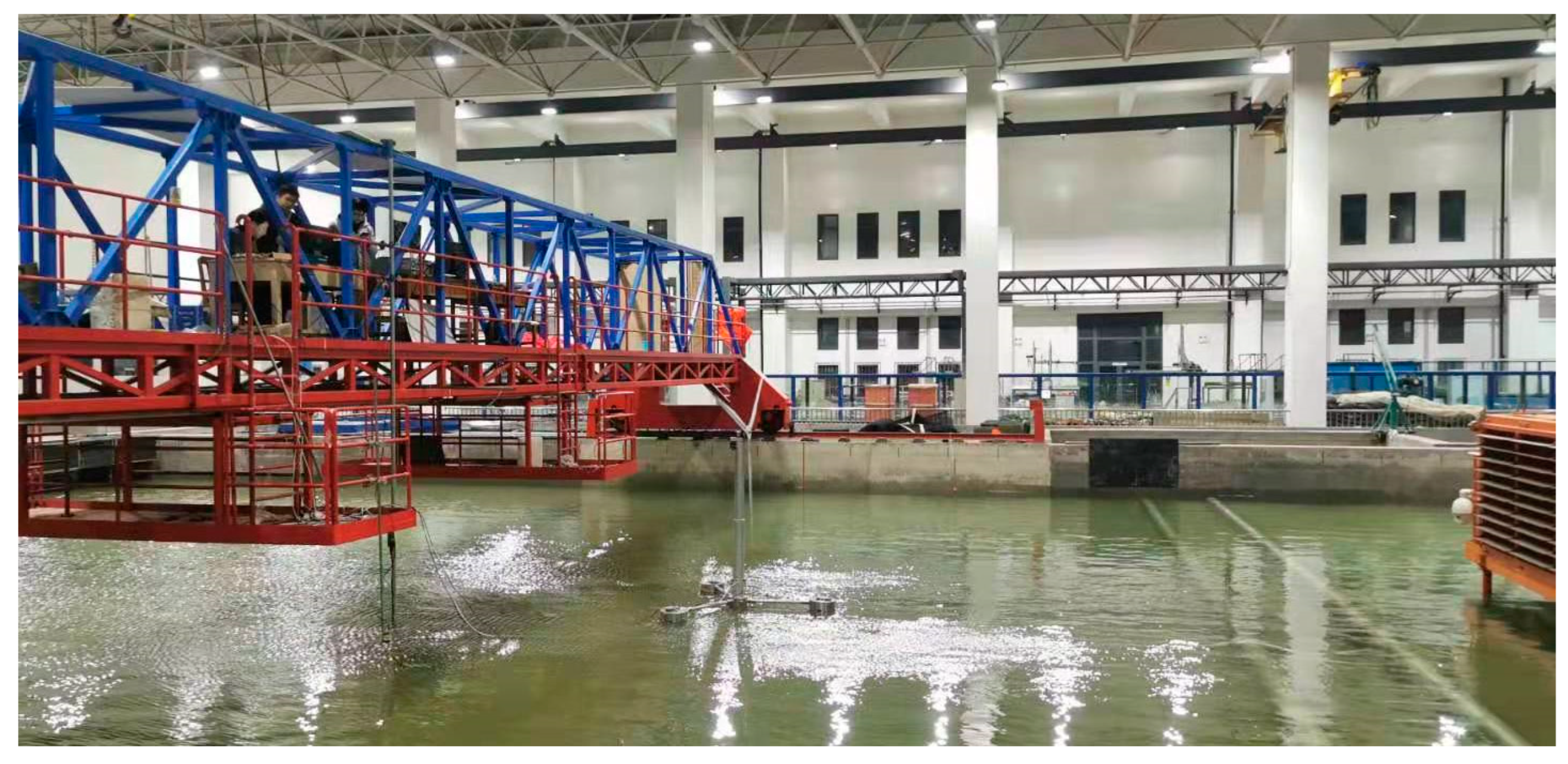
2. Test Method and Condition Parameters

In the design of a physical model test, it is essential to account for the appropriate similarity criterion. The current experiment addresses hydrodynamic and dynamic issues influenced by gravitational forces. Consequently, the Froude similarity criterion is employed, with the model being constructed in accordance with geometric similarity conditions:
V p g L p = V m g L m
where, Vp, Vm denote the characteristic speeds (m/s) of the prototype and the model, respectively, while Lp, Lm represent the characteristic geometric lengths (m) of the prototype and the model, respectively. The subscripts p and m correspond to the prototype and model, respectively. g signifies the acceleration due to gravity. This framework facilitates the derivation of a conversion relationship between the model and the prototype concerning geometric length, motion speed, motion period, force, and structural stiffness, as illustrated in Table 1. The conversion coefficient is a function of the model scale (λ).
In this study, the semi-submersible foundation consists of four floating vertical cylinders, as illustrated in Figure 1a. A central floating vertical cylinder, with an outer diameter of 10 m, is surrounded by three additional cylinders, each with an outer diameter of 14 m, arranged in a triangular configuration in the plan view. The wind turbine is mounted on the central floating cylinder. All floating vertical cylinders are interconnected by rigid frames, forming a cohesive structure. The horizontal dimension of the foundation measures 78 m, with a design draft of 10 m. The environmental conditions for the prototype are defined by a water depth of 40.0 m. Under a one-year wave load scenario, the conditions are characterized by a significant wave height (Hs) of 5.51 m and a peak wave period (Tp) of 9.0 s. In contrast, a fifty-year wave load scenario is characterized by Hs = 12 m and Tp = 12.7 s. To systematically examine the impact of wave parameters on the response of the floating wind turbine, a broader spectrum of wave parameters is employed, with wave heights ranging from 1.0 m to 10.5 m and wave periods from 5.6 s to 14.5 s. Additionally, the current velocity is maintained at a constant U = 0.96 m/s, while wind speeds vary from 11 m/s to 36 m/s.
Experiments were conducted in a wave tank located at the Harbor Engineering Laboratory of the State Key Laboratory of Hydraulic Engineering Intelligent Construction and Operation, Tianjin University. The primary basin measures 36 m in length, 24 m in width, and 1.2 m in depth, with a maximum water depth of 1.0 m. A wind fan is positioned between the wave maker and the semi-submersible foundation to generate a wind field aligned with the direction of wave propagation. Taking into account the dimensions of the prototype floating wind turbine and the capabilities of the experimental facility, a model scale of 1:50 was selected. Thus, the design of the floating submersible foundation model is as follows: the outer diameters of the central and surrounding floating cylinders are 0.20 m and 0.28 m, respectively. The horizontal dimension of the floating foundation measures 1.56 m, with a draft of 0.2 m. The test model is constructed from stainless steel, adhering to the similarity criteria outlined in Table 1. The dimensions and mass specifications of the floating wind turbine, pertaining to both the prototype and the model, are presented in Table 2 and Table 3. A photograph of the floating turbine is presented in Figure 1b. The experimental setup is depicted in Figure 2, with the following details: (1) two wave probes are employed to measure real-time wave height in front of the model; (2) an anemometer is utilized to measure wind speed in front of the foundation; (3) an accelerometer is positioned on the middle pontoon to analyze real-time displacement response; and (4) an angular accelerometer is installed at the top of the wind turbine tower to measure the inclination angle of the foundation.
The study adheres to the Froude similarity for both the size of the wind blade and its rotational speed. Meanwhile, the wind speeds for both the prototype and model are adjusted according to the Froude similarity of the total wind force exerted on the wind turbine, expressed as Fp/Fm = λ3. Here, the total wind force on the prototype, Fp, is defined as (1/2)ρCdApWp, where Ap represents the sweeping area of the wind blade, Wp denotes the prototype wind speed, Cd is the drag coefficient, and ρ is the air density. The total wind force for the model, Fm, is calculated using the same methodology. The specific test conditions are as follows: water depth d = 0.8 m, wave height H = 0.02~0.21 m, wave period T = 0.8~2.1 s, current velocity U = 0.14 m/s, and wind speed W = 0.5~1.6 m/s. Table 4 presents the environmental conditions applicable to both the prototype and model of the floating wind turbine. Figure 3 presents a photograph of the model test conducted in the wave basin. The experiments encompass a series of working conditions, including scenarios with waves alone, combined wind and waves, and combined wind, wave, and current conditions. Both regular and irregular wave conditions are considered. The planar arrangement of the semi-submersible foundation consists of one surrounding floating cylinder aligned with the wave direction, while the other two surrounding floating cylinders are positioned perpendicular to it, as depicted in Figure 2b. Two mooring configurations are assessed, as illustrated in Figure 2c,d. In mooring configuration 1, a single mooring line is connected to the base of the central floating cylinder and extends upstream towards the wave maker, with its lower end anchored to the floor of the wave basin. In mooring configuration 2, three mooring lines are attached to the bases of the three surrounding floating cylinders, extending outward from the floating wind turbine at 120° intervals.

3. Results and Discussion

3.1. The Dynamic Responses of the Floating Wind Turbine Under Different Conditions

Under typical environmental conditions, floating wind turbines exhibit six degrees of freedom in their motion. This study primarily focuses on the pitch and roll responses of the floating turbine, emphasizing design and operational safety. Furthermore, it analyzes how these responses vary with key hydrodynamic parameters.

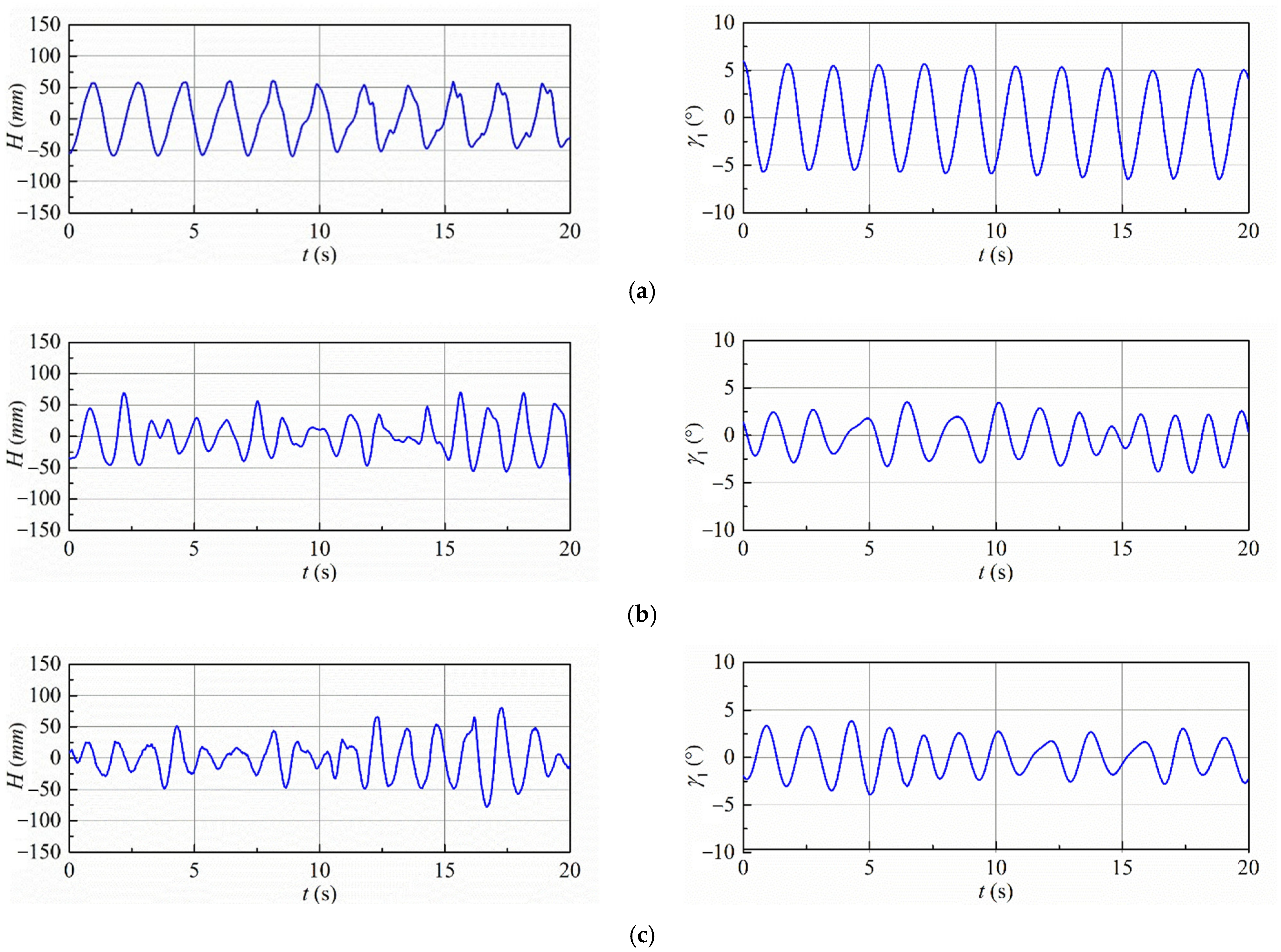
3.1.1. Time Histories of the Incident Waves and Responses

Figure 4 presents a series of typical temporal evolution of incident wave elevation and the pitch response of a floating wind turbine directly measured in tests. A configuration with three mooring lines is applied. In this figure, the left column illustrates the incident wave elevation across different conditions, while the right column depicts the corresponding pitch response of the floating wind turbine. The pitch motion is defined as the inclination angle in the direction of wave propagation. Given that the wind and current are aligned with the wave direction, the pitch angle is specifically analyzed to assess the response of the semi-submersible foundation. Figure 4a,b present the results for regular and irregular waves, respectively. The pitch responses generally exhibit a trend similar to that of the incident wave elevations. In Figure 4a, the wave period is greater than that in Figure 4b, resulting in a significantly larger pitch response in the former, despite the wave heights being identical in both cases. In Figure 4c, wind effects are superimposed on the conditions of Figure 4b; however, the pitch response in Figure 4c is slightly smaller than that in Figure 4b. Figure 4d illustrates the results under the combined influence of waves, current, and wind. The shape of the pitch response in this scenario is consistent with that observed under wave-only or combined wave and wind conditions. In this case, the wave period is relatively larger than those in Figure 4a–c, resulting in the largest pitch response values among these four cases. It is observed from Figure 4 that the amplitudes of the pitch response of the floating wind turbine vary across different conditions, influenced by factors such as wave height, wave period, wind speed, and current speed, even when considering both regular and irregular wave patterns.

3.1.2. Response Amplitude Under Different Conditions

The pitch and roll response amplitudes of the floating wind turbine under various conditions are derived from their respective time histories. In the context of regular waves, both the incident wave height and the corresponding response exhibit periodic characteristics. Consequently, the response amplitude is determined by averaging the response amplitudes over each period, denoted as γ. Conversely, for irregular waves, the significant wave height is utilized, and the response amplitude is defined as the average of the highest one-third of response amplitude values. This approach parallels the calculation method for significant wave height and is denoted as γ1/3. Regarding the application to practical engineering design, the subsequent discussions present the response amplitude and environmental conditions using prototype values (Figure 5, Figure 6, Figure 7, Figure 8, Figure 9, Figure 10, Figure 11, Figure 12, Figure 13, Figure 14 and Figure 15), which are converted based on the Froude similarity criterion.
In contrast to the periodic effects of wave action on floating wind turbines, wind forces typically induce a steady inclination angle rather than periodic oscillations. Figure 5a,b depict the variations in the inclination angle of the floating wind turbine under wind-only conditions, comparing scenarios with one mooring line and three mooring lines, respectively. It should be noted that under wind-only conditions, γ represents the steady inclination angle of the wind turbine. The inclination angle generally increases with rising wind speeds up to 16 m/s, beyond which the rate of increase in response amplitude becomes more gradual. This phenomenon can be attributed to the horizontal drift of the floating wind turbine towards the leeward side under wind actions, which increases the tension in the mooring line, thereby enhancing the stability of the turbine. Overall, the dynamic response of the floating wind turbine is minimal under wind-only conditions. The experiments conducted by Guo et al. [24] corroborate these findings, indicating that the dynamic response of a floating wind turbine with semi-submersible foundations remains relatively small under wind-only conditions. Specifically, the maximum inclination angle is approximately 0.35° in the scenario with one mooring line and approximately 0.22° in the scenario with three mooring lines.
Figure 5. Variation of the inclination angle with the wind speed for the floating wind turbine under wind-only conditions: (a) with one mooring line, (b) with three mooring lines.
Water 17 01501 g005
Figure 6a,b illustrate the response amplitudes of pitch and roll of a floating wind turbine subjected to regular and irregular waves, respectively, with a single mooring line. The response amplitude under irregular wave conditions is denoted as γ1/3 and is computed using the same methodology as for the significant wave height described earlier. In Figure 6, the wave period for regular waves and the peak period for irregular waves are both set at T (Tp) = 9.2 s. Generally, the amplitude of pitch and roll responses exhibits a linear increase with rising wave height for both regular and irregular wave conditions. Notably, the pitch response amplitude is significantly greater than the roll response amplitude. The trends in pitch and roll response amplitudes are consistent across both regular and irregular wave conditions.
Figure 6. Variation of the pitch and roll angle with the wave height for the floating wind turbine with one mooring line: (a) under regular waves, T = 9.2 s, (b) under irregular waves, Tp = 9.2 s.
Water 17 01501 g006
Figure 7 illustrates the response amplitudes of pitch and roll for the floating wind turbine subjected to regular wave conditions, utilizing three distinct mooring line configurations. In Figure 7a, the response amplitudes of pitch and roll exhibit linear increase as the wave height escalates, given a constant wave period of T = 12.7 s. Conversely, Figure 7b demonstrates that both pitch and roll response amplitudes increase in an increasing manner as the wave period increases, for a constant wave height of H = 4.0 m. Generally, the response amplitude of a floating wind turbine system has a peak value when the wave period approaches the system’s natural period, subsequently decreasing as the wave period further extends. However, in the present study, under the most prevalent wave conditions, the pitch response amplitude remains in an ascending phase and has not yet attained its peak value. This observation suggests that the natural period of the floating turbine is intentionally designed to be distant from the most frequently occurring wave conditions. It is also observed that the amplitude of the pitch response consistently exceeds that of the roll response.
Figure 7. The pitch and roll angle of the floating wind turbine varying with (a) the wave height, T = 12.7 s, and (b) the wave period, H = 4.0 s, for regular waves.
Water 17 01501 g007
Figure 8a,b illustrate the response amplitudes of pitch and roll of the floating wind turbine subjected to irregular wave conditions, specifically for Tp = 9.2 s and 12.7 s. In general, the response amplitudes of both pitch and roll exhibit linear increase with the rise in significant wave height under irregular wave conditions. Notably, the pitch response amplitude is greater than that of the roll response.
Figure 8. Variation of the pitch and roll response amplitudes with the wave height for the floating wind turbine under irregular waves: (a) T = 9.2 s, (b) T = 12.7 s.
Water 17 01501 g008
Figure 9a,b illustrate the pitch and roll response amplitudes of the floating wind turbine subjected to irregular wave and wind conditions, utilizing three mooring lines. The peak wave period is consistently set at Tp = 9.2 s for both scenarios, with wind speeds of W = 16 m/s and 36 m/s, respectively. When wind conditions are superimposed on wave conditions, the overall trend in the pitch and roll responses of the floating wind turbine remains consistent with those observed under wave-only conditions. Notably, the amplitude of pitch and roll responses increases linearly with rising wave height. However, an intriguing observation is that the pitch and roll response amplitudes at W = 36 m/s are smaller than those at W = 16 m/s. This phenomenon will be further examined in Section 3.2.
Figure 9. Variation of the pitch and roll response amplitude with the wave height for the floating wind turbine under irregular waves + wind: (a) T = 9.2 s, W = 16 m/s, (b) T = 9.2 s, W = 36 m/s.
Water 17 01501 g009
Figure 10 illustrates the pitch and roll response amplitude of the floating wind turbine under combined conditions of regular waves, wind, and current, utilizing three mooring lines. The wind speed is W = 11 m/s, and the current speed is U = 0.95 m/s. In Figure 10a, the amplitude of pitch and roll responses increases linearly with the rise in wave height, whereas in Figure 10b, both responses exhibit a nonlinear increase with the wave period. It is noteworthy that, consistent with the conditions of waves only and waves combined with wind, the roll response amplitudes remain significantly smaller than the pitch response amplitudes.
Figure 10. Variation of the pitch and roll response amplitude with the wave height for the floating wind turbine under waves + wind + current conditions: (a) T = 9.2 s, W = 11 m/s, U = 0.96 m/s, (b) H = 4.0 m/s, W = 11 m/s, U = 0.96 m/s.
Water 17 01501 g010

3.2. Effect of Main Parameters on Dynamic Response

Despite the symmetrical structure and configuration of the system in relation to incoming waves, wind, and current, installation errors during the placement of the floating wind turbine in the wave basin, along with imperfections in the wave and wind fields, result in disturbances that can induce roll responses. However, these roll responses are generally minor compared to the pitch responses, particularly under combined wave and wind conditions, or when waves, wind, and current are combined. Consequently, the present study primarily focuses on analyzing the pitch response angle. Regarding the definition of stability, we adhere to the standard for floating wind turbines as stated by Huijs et al. [3], which stipulates that the maximum inclination angle should not exceed 10°. Consequently, this study primarily concentrates on the pitch response, ensuring that the pitch response amplitude remained below 10°.

3.2.1. Effect of Mooring Method

The comparative analysis of the pitch angle for two distinct mooring methods under identical wave conditions is illustrated in Figure 11. Figure 11a,b depict the variations in pitch response amplitude relative to wave height for a constant wave period in both regular (T = 9.2 s) and irregular waves (Tp = 9.2 s). For irregular waves, the significant wave height is employed, and the pitch response amplitude is represented by the maximum 1/3 average value, denoted as γ1/3. Overall, the variation trends for both the one mooring line and the three mooring lines configurations are analogous, with the pitch response amplitude exhibiting a linear increase as wave height escalates. Notably, the pitch response amplitude of the floating wind turbine with three mooring lines is smaller compared to that with one mooring line, suggesting that the three-mooring-line method is more effective than the one-mooring-line approach. In the single-mooring-line configuration, the mooring line is anchored to the base of the central floating vertical cylinder. Conversely, in the configuration with three mooring lines, each line is attached to the surrounding floating cylinders as shown in Figure 2c,d. Consequently, the mooring reaction moments in the latter configuration are significantly greater than those in the former, thereby enhancing the stability of the floating wind turbine and reducing its response amplitude.
Figure 11. Comparisons of the pitch response amplitude between the one-mooring-line and three-mooring-lines methods: (a) regular waves, T = 9.2 s, (b) irregular waves, Tp = 9.2 s.
Water 17 01501 g011

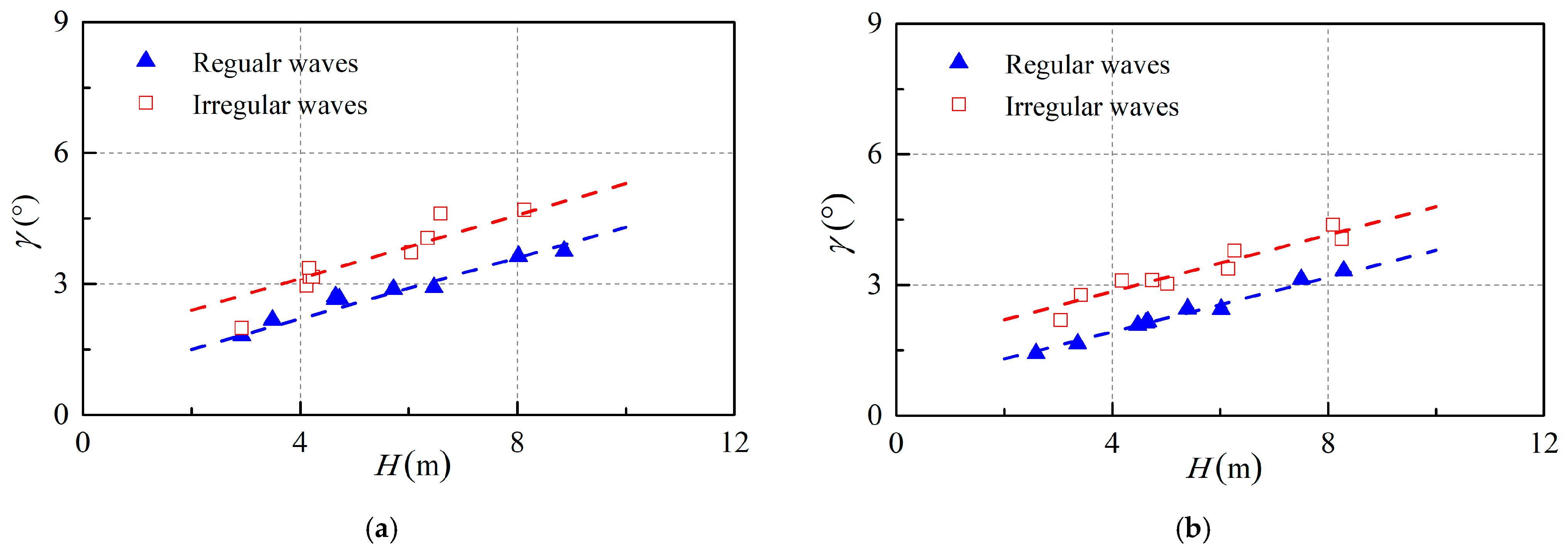
3.2.2. Effect of Regular and Irregular Waves

Figure 12 presents a comparative analysis of the pitch response amplitude of a floating wind turbine subjected to both regular and irregular waves. The wave period is specified as T (Tp) = 9.2 s, reflecting prototype conditions. The analysis considers configurations with both one mooring line and three mooring lines, as illustrated in Figure 12a,b, respectively. In general, the amplitude of the pitch response exhibits a linear increase with rising wave height in both regular and irregular wave conditions. In the current study, the results derived from irregular waves are 20% greater than those from regular waves. However, due to the limited sample size, it cannot be conclusively determined that the results for irregular waves are universally larger than those for regular waves under all conditions, as this may be influenced by various factors, such as wave period. Further investigations with a broader range of test cases are necessary to substantiate these findings.
Figure 12. Comparisons of the pitch response amplitude between regular and irregular waves, T (Tp) = 9.2 s: (a) with one mooring line, (b) with three mooring lines.
Water 17 01501 g012

3.2.3. Effect of Wave Period

Figure 13 presents a comparison of the pitch response amplitude of a floating wind turbine at different wave periods under both regular and irregular wave conditions. The analysis considers three-mooring-line configurations and compares two wave periods, T (Tp) = 9.2 s and T (Tp) = 12.7 s. As previously discussed, the pitch response amplitudes increase with wave height. Notably, the pitch response amplitude for T (Tp) = 12.7 s is significantly larger than that for T (Tp) = 9.2 s, attributed to the exponential increase in pitch response amplitude with increasing wave period. This finding indicates that wave period exerts a substantial influence on the stability of the floating wind turbine. Additionally, it is observed that the maximum pitch response amplitude under regular wave conditions exceeds 10°, posing a potential risk to the safe operation of the floating wind turbine.
Figure 13. Comparisons of the pitch response amplitude among difference wave periods with three mooring lines: (a) regular waves, (b) irregular waves.
Water 17 01501 g013

3.2.4. Effect of Superimposition of Wind

Figure 14 presents the results for the combined effects of irregular waves and wind load. Prior to conducting experiments on the combined effects of waves and wind, tests were performed under wind-only conditions. The pitch angle under pure wind conditions was found to be less than 0.3°, even at a wind speed of W = 36.0 m/s; therefore, these results are not included here. In Figure 14a, the wind speed is set at W = 11.0 m/s with one mooring line employed. In Figure 14b, two wind speeds, W = 16.0 m/s and 36.0 m/s, are examined with three mooring lines. The results for wave-only conditions are also plotted to assess the impact of superimposed wind on wave effects for comparative analysis. It is observed that the pitch angle of the wind turbine structure decreases when subjected to the combined wind load, suggesting an enhancement in the stability of the floating wind turbine due to the superimposed wind load. This phenomenon can be attributed to the wind causing a steady drift of the floating wind turbine towards the leeward side, resulting in the tensioning of the mooring line and an increase in the spring constant. Consequently, the pitch response amplitudes are attenuated when wind forces are superimposed on waves. Guo et al. [24] also demonstrated a reduction in the pitch motion of the floating wind turbine when subjected to combined wind conditions, as opposed to scenarios without wind. The current study suggests that higher wind speeds lead to a more significant reduction in pitch response amplitude. These findings offer valuable insights for the selection of design loads for wind turbine structures, particularly when considering the combined effects of wind.
Figure 14. Comparisons of the pitch response amplitude between wave-only and wave + wind conditions, Tp = 9.2 s: (a) with one mooring line, (b) with three mooring lines.
Water 17 01501 g014

3.2.5. Effect of Superimposition of Wind and Current

Figure 15 illustrates the pitch response amplitude of the floating wind turbine under combined wave, current, and wind conditions. For comparative purposes, the results for wave-only conditions are also presented. Figure 15a depicts the variation in pitch response amplitude with respect to wave height, maintaining a constant wave period of T = 9.2 s. The findings suggest that the pitch response amplitude of the floating wind turbine under combined wave, current, and wind conditions closely resembles that observed under wave-only conditions. This study does not incorporate a specific test condition for the combination of waves and current. It is evident that the addition of current does not enhance the response amplitude of the floating wind turbine. Furthermore, Guo et al. [24] observed that the inclusion of current can diminish the motion response. The impact of the combined forces of wind, wave, and current can be elucidated as follows: the wind load primarily influences the system via the rotor and tower; the wave load affects the platform at the water’s surface; and the current load impacts the system through the platform and mooring lines. The wind load and current load are inversely related to the center of inertia concerning the pitch response, thereby enabling the current load to counteract the wind load [24]. Concurrently, the mooring lines experience increased tension due to steady drift induced by the combined effects of wind and current, which subsequently enhances the spring constant. This enhancement contributes to the attenuation of system vibrations to a certain extent. These findings indicate that the pitch response amplitude under the combined effects of wave, current, and wind loads is generally comparable to, or even less than, that observed under wave-only loads, which tend to produce the largest pitch response amplitude among the various load combinations.
Figure 15. Comparisons of the pitch response amplitude between wave-only and wave + wind + current conditions with three mooring lines, U = 0.96 m/s: (a) varying with wave height, T = 9.2 s, (b) varying with wave period, H = 4.0 m.
Water 17 01501 g015

4. Conclusions

In this study, a model of a semi-submersible wind turbine foundation was developed based on the gravity similarity criterion, and stability tests were conducted in a three-dimensional wave basin. The model was constructed at a 1:50 scale, and the impact of wave, current, and wind loads, as well as their combined effects on the stability of the floating wind turbine, were examined. The primary focus was on analyzing the pitch response amplitude of the floating wind turbine to validate its design. The analysis of the experimental results led to several key conclusions:
(1)
A comparative analysis of mooring techniques demonstrated that employing three mooring lines attached to the three surrounding floating cylinders, rather than a single mooring line connected to the central floating cylinder, significantly reduces the pitch response amplitude of the floating wind turbine.
(2)
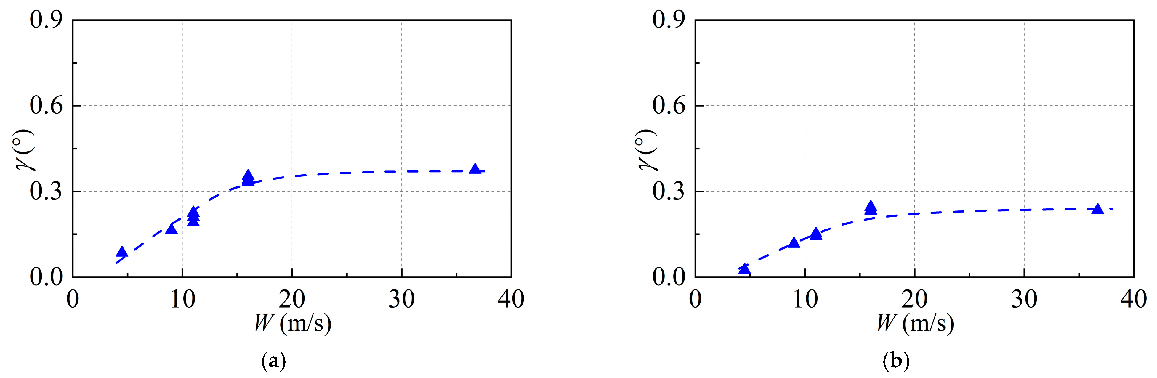
The floating wind turbine demonstrates a steady inclination when subjected to wind-only conditions. Nevertheless, this inclination angle remains notably minimal, with a maximum value not exceeding 0.3° under the maximum design wind load.
(3)
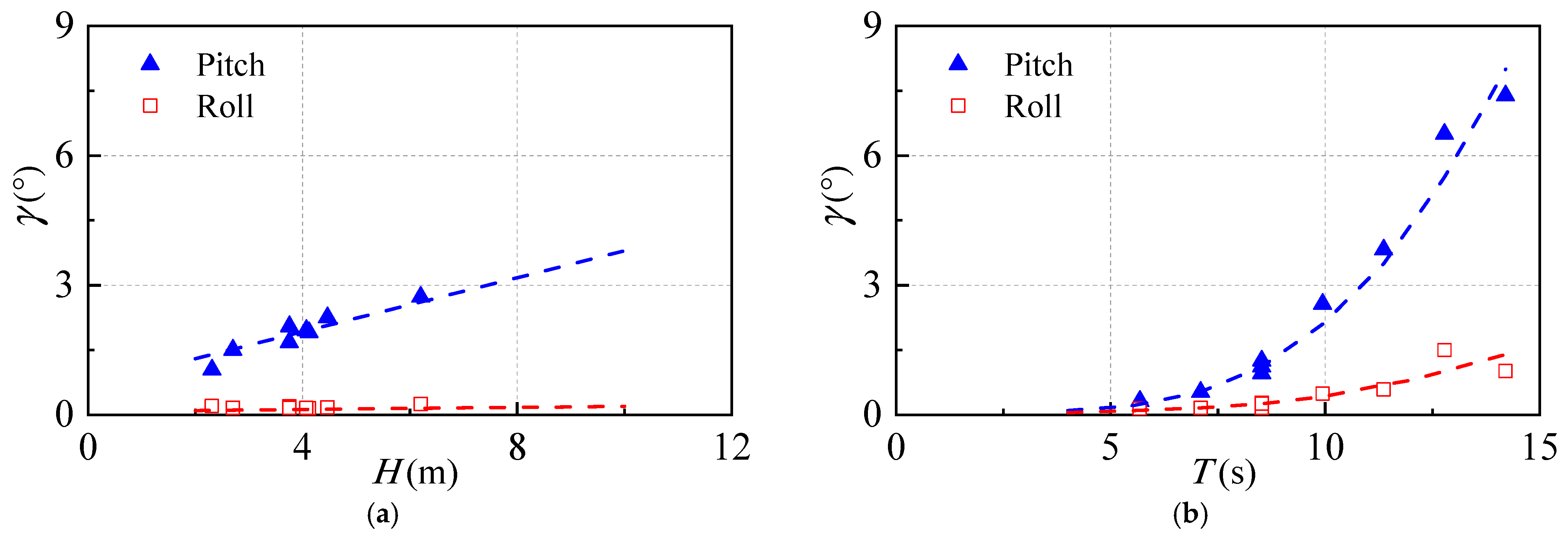
Within the examined range of wave periods, the amplitude of the pitch response exhibits an increasing trend without reaching a peak value. This observation suggests that the natural period of the floating wind turbine is intentionally designed to be distinct from the most frequently occurring wave conditions in actual marine environments. Under a one-year wave load, characterized by a significant wave height (Hs) of 5.51 m and a peak wave period (Tp) of 9.0 s, the pitch response amplitude is approximately 4°. Conversely, under a fifty-year wave load with Hs = 12 m and Tp = 12.7 s, the pitch response amplitude increases to 7°. Both amplitudes remain within the standard inclination angle limit of 10° for a floating wind turbine.
(4)
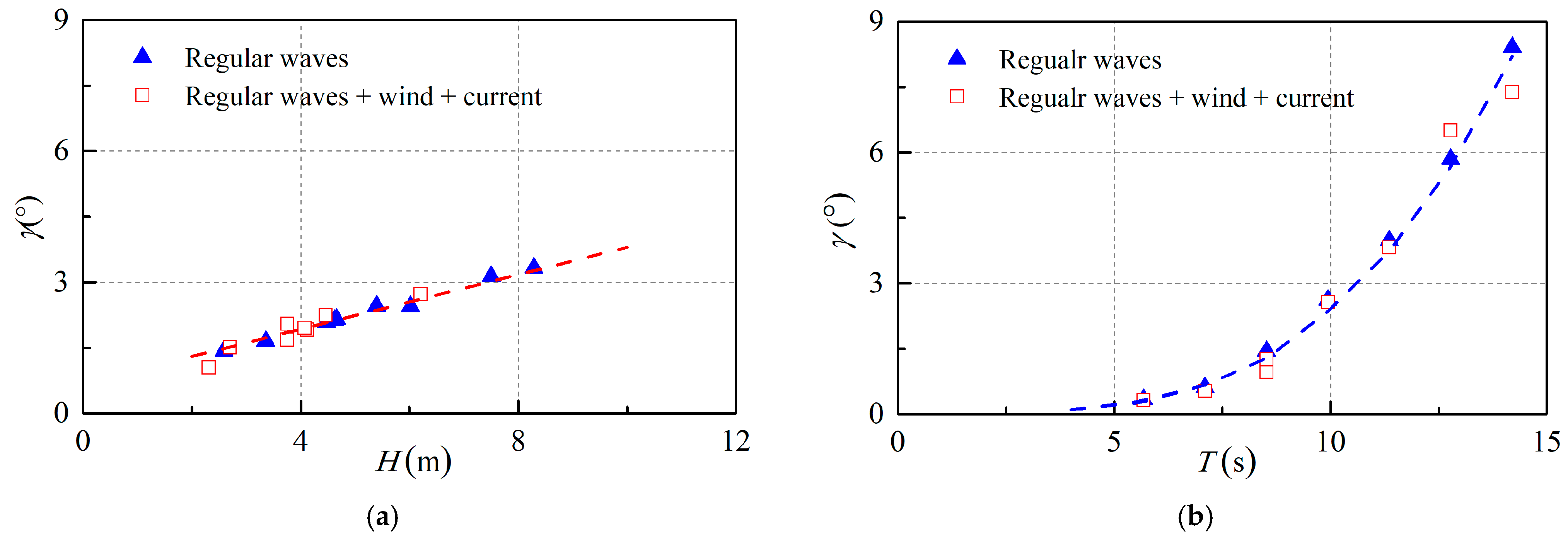
When wave and wind loads are combined, the resulting pitch response amplitude of the floating wind turbine is marginally diminished compared to the amplitude generated by wave load alone. This phenomenon is predominantly due to the increased spring constant of the mooring lines, which is caused by the steady drift of the floating wind turbine towards the leeside under the influence of wind.
(5)
When wave, current, and wind loads are combined, the pitch response amplitude of a floating wind turbine closely approximates that induced by wave loads alone. The wind load predominantly affects the system through the rotor and tower, whereas the current load influences the system via the platform and mooring lines. The wind and current loads exhibit an inverse relationship with respect to the center of inertia concerning the pitch response, thereby allowing the current load to counterbalance the wind load. Simultaneously, the mooring lines experience increased tension due to the steady drift induced by wind and current, which subsequently enhances the spring constant. These enhancements contribute to the attenuation of system vibrations to a certain extent.
The experimental results presented here offer crucial data for the design of floating wind turbines with semi-submersible foundations and serve as validation data for numerical simulations.

Author Contributions

Conceptualization, Z.Z. and Z.F.; methodology, Z.Z. and H.Z.; validation, H.Z. and Z.F.; investigation, Z.Z., Z.F. and H.Z.; resources, Z.F. and J.Z.; data curation, H.Z.; writing—original draft preparation, Z.Z., H.Z and Z.F.; writing—review and editing, Z.Z. and C.H.; visualization, H.Z.; supervision, J.Z. and C.H.; project administration, J.Z. and C.H.; funding acquisition, Z.Z. and C.H. All authors have read and agreed to the published version of the manuscript.

Funding

This research was funded by National Natural Science Foundation of China (51979192, 52371289), the Shenzhen Science and Technology Program (No. GJHZ20220913142612023), and the Guangdong Science and Technology Program (No. 2021ZT09H390), the Shenzhen Science Technology Program (No. KQTD20200820113011026).

Data Availability Statement

Data from the present experiment appear in the submitted manuscript.

Acknowledgments

The authors also thank the anonymous reviewers for their helpful comments and suggestions.

Conflicts of Interest

The authors declare that they have no known competing financial interests or personal relationships that could have appeared to influence the work reported in this paper.

References

  1. Liu, Y.; Li, S.; Yi, Q.; Chen, D. Developments in semi-submersible floating foundations supporting wind turbines: A comprehensive review. Renew. Sus. Energ. Rev. 2016, 60, 433–449. [Google Scholar] [CrossRef]
  2. Casale, C.; Lembo, E.; Serri, L.; Viani, S. Preliminary design of a floating wind turbine support structure and relevant system cost assessment. Wind Eng. 2010, 34, 29–50. [Google Scholar] [CrossRef]
  3. Huijs, F.; Bruijn, R.; Savenije, F. Concept design verification of a semi-submersible floating wind turbine using coupled simulations. Energy Procedia 2014, 53, 2–12. [Google Scholar] [CrossRef]
  4. Collu, M.; Maggi, A.; Gualeni, P.; Rizzo, C.M.; Brennan, F. Stability requirements for floating offshore wind turbine (FOWT) during assembly and temporary phases: Overview and application. Ocean Eng. 2014, 84, 164–175. [Google Scholar] [CrossRef]
  5. Yao, Y.; Mayon, R.; Zhou, Y.; Zhu, Y.; Ning, D. Integrated system of semi-submersible offshore wind turbine foundation and porous phells. J. Mar. Sci. Appl. 2024, 23, 491–505. [Google Scholar] [CrossRef]
  6. Pan, Q.; Wang, X.; Li, S.; Zhang, L.; Zhou, X. Multi-objective design and optimization method for semi-submersible wind turbine considering stability constraints. Ocean Eng. 2025, 321, 120350. [Google Scholar] [CrossRef]
  7. Chakrabarti, S.; Barnett, J.; Kanchi, H.; Mehta, A.; Yim, J. Design analysis of a truss pontoon semi-submersible concept in deep water. Ocean Eng. 2007, 34, 621–629. [Google Scholar] [CrossRef]
  8. Cao, Q.; Xiao, L.; Cheng, Z.; Liu, M.; Wen, B. Operational and extreme responses of a new concept of 10 MW semi-submersible wind turbine in intermediate water depth: An experimental study. Ocean Eng. 2020, 217, 108003. [Google Scholar] [CrossRef]
  9. Li, Q.; Gao, Z.; Moan, T. Modified environmental contour method to determine the long-term extreme responses of a semi-submersible wind turbine. Ocean Eng. 2017, 142, 563–576. [Google Scholar] [CrossRef]
  10. Chen, J.; Hu, Z.; Liu, G.; Wan, D. Coupled aero-hydro-servo-elastic methods for floating wind turbines. Renew. Energ. 2019, 130, 139–153. [Google Scholar] [CrossRef]
  11. Cheng, P.; Huang, Y.; Wan, D. A numerical model for fully coupled aero-hydrodynamic analysis of floating offshore wind turbine. Ocean Eng. 2019, 173, 183–196. [Google Scholar] [CrossRef]
  12. Raed, K.; Teixeira, A.P.; Guedes Soares, C. Uncertainty assessment for the extreme hydrodynamic responses of a wind turbine semi-submersible platform using different environmental contour approaches. Ocean Eng. 2020, 195, 106719. [Google Scholar] [CrossRef]
  13. Li, H.; Zheng, J.; Zhang, J.; Peng, W.; Peng, J. Numerical investigation on dynamic responses of a semi-submersible wind turbine with different types of heave plates. Ocean Eng. 2024, 310, 118650. [Google Scholar] [CrossRef]
  14. Wang, B.; Gao, X.; Li, Y.; Liu, L.; Li, H. Dynamic response analysis of a semi-submersible floating wind turbine based on different coupling methods. Ocean Eng. 2024, 297, 116948. [Google Scholar] [CrossRef]
  15. Zhang, Y.; Li, T.; Yang, Q.; Wei, K.; Zhang, Z. Hydrodynamic model for a semi-submersible wind turbine platform with effects of ocean currents. Ocean Eng. 2024, 313, 119517. [Google Scholar] [CrossRef]
  16. Hu, Z.; Jin, J.; Chen, P.; Cheng, Z.; Gao, Z. Numerical modelling and dynamic response analysis of dockside installation of a semi-submersible floating wind turbine considering multi-stage typhoon. Ocean Eng. 2025, 325, 120751. [Google Scholar] [CrossRef]
  17. Lopez-Pavon, C.; Souto-Iglesias, A. Hydrodynamic coefficients and pressure loads on heave plates for semi-submersible floating offshore wind turbines: A comparative analysis using large scale models. Renew. Energ. 2015, 81, 864–881. [Google Scholar] [CrossRef]
  18. Liu, J.; Thomas, E.; Goyal, A.; Manuel, L. Design loads for a large wind turbine supported by a semi-submersible floating platform. Renew. Energ. 2019, 138, 923–936. [Google Scholar] [CrossRef]
  19. Stansby, P.K.; Moreno, E.C.; Apsley, D.D.; Stallard, T.J. Slack-moored semi-submersible wind floater with damping plates in waves: Linear diffraction modelling with mean forces and experiments. J. Fluids Struc. 2019, 90, 410–431. [Google Scholar] [CrossRef]
  20. Payenda, M.A.; Wang, S.; Jiang, Z.; Prinz, Z. Prediction of mooring dynamics for a semi-submersible floating wind turbine with recurrent neural network models. Ocean Eng. 2024, 313, 119490. [Google Scholar] [CrossRef]
  21. Bertozzi, A.; Niosi, F.; Jiang, X.; Jiang, Z. Numerical calibration of the mooring System for a semi-submersible floating wind turbine model. J. Offshore Mech. Arct. Eng. 2024, 146, 062001. [Google Scholar] [CrossRef]
  22. Jiang, Y.; Chen, P.; Wang, S.; Cheng, Z.; Xiao, L. Dynamic responses of a 5 MW semi-submersible floating vertical-axis wind turbine: A model test study in the wave basin. Ocean Eng. 2024, 296, 117000. [Google Scholar] [CrossRef]
  23. Bai, H.; Xu, K.; Zhang, M.; Yuan, W.; Jin, R.; Li, W.; Gao, S.; Li, H. Theoretical and experimental study of the high-frequency nonlinear dynamic response of a 10MWsemi-submersible floating offshore wind turbine. Renew. Energ. 2024, 231, 120952. [Google Scholar] [CrossRef]
  24. Guo, J.; Liu, M.; Fang, Z.; Chen, W.; Pan, X.; Yang, J. An experimental study on the influence of wind-wave-current coupling effect on the global performance of a 12 MW semi-submersible floating wind turbine. Ocean Eng. 2024, 304, 117795. [Google Scholar] [CrossRef]
  25. Zhao, Z.; Chang, S.; Li, X.; Liu, F. Experimental study on dynamic responses of a new semi-submersible supporting platform concept for 10 MW wind turbines. Ocean Eng. 2025, 318, 120168. [Google Scholar] [CrossRef]
Figure 1. (a) Illustration of the floating wind turbine; (b) photograph of the floating wind turbine model.
Water 17 01501 g001
Figure 2. (a) Experimental setup within the wave basin, (b) a planar configuration of the semi-submersible foundation, (c) a configuration of a single mooring line, and (d) a configuration involving three mooring lines.
Water 17 01501 g002
Figure 3. Photograph of the model test in the wave basin.
Water 17 01501 g003
Figure 4. Time histories of wave elevations and pitch response of the floating wind turbine with three mooring lines. The left column is the wave surface elevation and the right column is the pitch response. (a) T = 1.8 s, H = 0.10 m, U = 0 m/s, W = 0 m/s; (b) Tp = 1.3 s, Hs = 0.10 m, U = 0 m/s, W = 0 m/s; (c) Tp = 1.3 s, Hs = 0.10 m, U = 0 m/s, W = 1.6 m/s; (d) T = 2.0 s, H = 0.08 m, U = 0.12 m/s, W = 1.6 m/s.
Water 17 01501 g004aWater 17 01501 g004b
Table 1. The transformation between prototype and model variables.
Variable NameRelationship Between
Prototype and Model
Conversion Coefficient
Length (m)Lp/Lmλ
Speed (m/s)Vp/Vmλ1/2
Period (s)Tp/Tmλ1/2
Force (N)Fp/Fmλ3
Stiffness (N·m2)(EI)p/(EI)mλ5
Table 2. Dimensions of the floating wind turbine for both the prototype and the model (λ = 1:50).
Component and Total DimensionsPrototype ValuesModel Values
Diameter of surrounding cylinder R1 (m)14.00.28
Height of surrounding cylinder l1 (m)20.00.40
Draft of surrounding cylinder d1 (m)15.00.30
Diameter of central cylinder R2 (m)10.00.20
Height of central cylinder l2 (m)15.00.30
Draft of central cylinder d2 (m)10.00.20
Diameter of lower tube r1 (m)6.500.13
Height of lower tube b1 (m)40.00.80
Diameter of upper tube r1 (m)5.500.11
Height of upper tube b2 (m)45.00.90
Length of wind blade L1 (m)65.01.30
Length of floating foundation L (m)78.02.60
Diameter of rod d (m)1.500.04
Table 3. Mass of the floating wind turbine for both the prototype and the model (λ = 1:50).
Component and Total MassPrototype ValuesModel Values
Mass of tower tube (t)8.09 × 1026.16 × 10−3
Mass of wind turbine (t)3.52 × 1022.32 × 10−3
Mass of surrounding cylinder (t)3.55 × 1033.78 × 10−2
Mass of central cylinder (t)5.75 × 1025.94 × 10−3
Mass of connecting rod (t)2.61 × 1039.70 × 10−3
Total mass (t)7.85 × 1036.20 × 10−2
Table 4. Environmental conditions for both the prototype and the model (λ = 1:50).
Environmental ConditionsPrototype ValuesModel Values
Water depth d (m)40.00.8
Significant wave H (m)1.0~10.50.02~0.21
Wave period T (s)5.6~14.50.8~2.0
Current speed U (m/s)0.960.14
Wind speed W (m/s)11.0~36.0 0.5~2.0
Disclaimer/Publisher’s Note: The statements, opinions and data contained in all publications are solely those of the individual author(s) and contributor(s) and not of MDPI and/or the editor(s). MDPI and/or the editor(s) disclaim responsibility for any injury to people or property resulting from any ideas, methods, instructions or products referred to in the content.

