Article

Seismic Safety Analysis of Interlaminar Rock Mass in the Distributed Underground Reservoir of a Coal Mine

1
State Key Laboratory of Water Resource Protection and Utilization in Coal Mining, Beijing 102211, China
2
National Institute of Clean-and-Low-Carbon Energy, Beijing 102211, China
3
School of Civil Engineering, Wuhan University, Wuhan 430072, China
*
Author to whom correspondence should be addressed.
Water 2024, 16(3), 366; https://doi.org/10.3390/w16030366
Submission received: 13 November 2023 / Revised: 6 December 2023 / Accepted: 8 December 2023 / Published: 23 January 2024

Abstract

:
This study focuses on the seismic safety of distributed underground reservoirs in coal mines, especially in scenarios involving the establishment of multiple reservoirs within the same mining area, spanning different coal seams. Dynamic similarity model tests and numerical simulations are employed to investigate the construction and operation of these reservoirs under extreme conditions, such as mine tremors or earthquakes. Utilizing the Daliuta coal mine underground reservoir as a case study, a similarity material model test platform is established to represent both upper and lower coal mine underground reservoirs. Stability tests are conducted on the interlayer rock mass under various levels of seismic intensity, and the safety of the interlayer rock mass at different safety distances is comparatively analyzed. Meanwhile, using the finite element method, the responses of the upper and lower coal mine underground reservoirs under different seismic intensity levels are simulated with the same conditions of model tests. Through the two types of simulations, the mechanical response and safety of the surrounding rock of the Daliuta coal mine underground reservoir under the influence of different seismic intensities are systematically analyzed, and the reasonable safety distances between the upper and lower reservoirs are obtained. This study provides a valuable scientific insight into the safe design of underground reservoir embankments in coal mines.

1. Introduction

The distribution patterns of water resources and coal resources in China diverge. The coal-rich regions in its central and western parts often coincide with ecologically fragile areas characterized by arid and semi-arid conditions, where water resources are scarce, and surface ecosystems are particularly vulnerable [1,2,3,4]. In these major coal mining areas, water scarcity is a common challenge, leading to a heavy reliance on groundwater extraction and the comprehensive utilization of mine water for various purposes. The development of these mining regions is further complicated by the complexities of locating water sources, integrating water resource utilization, and allocating water rights [5,6,7,8,9,10]. The introduction of underground reservoir technology in coal mines serves as both a technical solution to address water shortages in mining areas and an effective approach to promote water conservation and utilization in western mining regions [3,11]. At its core, this technology leverages the rock cavities formed during coal mining to create water storage spaces. Discontinuous and secure coal pillars are connected by artificial dam structures to establish the reservoir dam [12,13,14]. Additionally, water intake facilities are constructed, making full use of the purifying properties of the rock cavities in the goaf to enhance the quality of mine water [15,16]. This innovative approach represents a novel form of underground water engineering structure. To optimize the utilization of the water storage space in the goaf, multiple underground water reservoirs are interconnected through water transfer channels, resulting in the creation of a distributed underground water reservoir within the coal mine [17], as depicted in Figure 1.
Safety is paramount during the construction and operation of distributed underground water storage in coal mines [18]. Under normal conditions, the technology for guarantying the safety of distributed underground water storage in coal mines is relatively mature [19]. For example, based on the actual conditions of the underground water storage in coal mines, relevant indicators and monitoring sensors are arranged to analyze key parameters, such as the stability of the reservoir’s weak areas, leakage, water level, water quality, water quantity, and dam stresses and strains [20,21]. Utilizing information monitoring technologies, the stability indicators for the dam can be monitored in real time [22]. On the other hand, surface water storage, which has been developed for over a hundred years, has formed different structural forms of dams and has been applied in engineering practice. In general, evaluating the safety and stability of a dam under earthquake conditions is an important aspect of the safe operation of surface water storage [23,24,25]. Scholars have conducted seismic safety evaluations of various types of dams and have achieved a series of results, providing a reference for analyzing and evaluating the seismic safety in distributed underground water storage in coal mines [26,27,28,29]. To evaluate the safety of underground reservoirs in the same coal seam under earthquakes, Gu et al. [1,6] were the first to propose evaluation methods for analyzing the dynamic response and stability of coal pillars in underground water reservoirs. They employed physical simulation and numerical simulation methods to conduct dynamic destruction tests on the dam body under different intensity conditions and compared the seismic safety with the dam body of surface water reservoirs under the same conditions, proposing the concept of safety factor for the dam body of underground water reservoirs in coal mines and providing a theoretical basis for the seismic evaluation of the dam body of underground water reservoirs in coal mines [6].
Compared to the underground water reservoirs in the same coal seam, the seismic safety evaluation of distributed underground water reservoirs in coal mines is more complex [26,29,30]. The reason for this is that the extraction of the lower coal seam causes significant changes in the stress field and fracture field between the upper and lower coal seams if an underground water reservoir has already been constructed in the upper coal seam [6,31]. In order to ensure the safety of the upper underground water reservoir, the extraction of the lower coal seam or the construction of the lower underground water reservoir must maintain a certain distance from the upper underground water reservoir. This distance is referred to as the safety distance between the upper and lower underground water reservoirs, as shown in Figure 2.
In this study, a similar material modeling experimental platform is established to simulate the safety of underground reservoirs above and below coal mines under earthquakes, especially applying for the Daliuta coal mine underground reservoir. This platform facilitates stability tests of the interlayer rock mass under various levels of seismic intensity. Then, the safety conditions of the interlayer rock mass under different safety distances are compared and analyzed. Meanwhile, the responses of the upper and lower coal mine underground reservoirs under different seismic intensity levels are simulated using the finite element method, considering the same conditions as the model tests. Through the two types of simulations, the mechanical response and safety of the surrounding rock of the Daliuta coal mine underground reservoir under the influences of different seismic intensities are systematically analyzed, and the reasonable safety distances between the upper and lower reservoirs are obtained. The results of this study provide valuable scientific insights into the safe design of underground reservoir embankments in coal mines.

2. Physical Model Experiments

2.1. Engineering Prototype

The engineering prototype chosen for this study is the distributed underground water reservoir in the Daliuta Coal Mine. The stratification and physical–mechanical parameters of the overlying rock layers are shown in Table 1.

2.2. Experiment Design

The purpose of the seismic safety physical model experiment of the underground water reservoir between the upper and lower rock layers in a coal mine is to simulate the stress–strain characteristics of the rock layers between coal seams at different distances from the excavation face during the excavation of the lower coal seam under seismic action. This is done to determine a reasonable safe distance from the upper coal water reservoir. The schematic diagram of the model is shown in Figure 3.
The upper and lower reservoir model comprises five layers: bedrock, a 5-2 coal seam, an intermediate rock layer, a 2-2 coal seam, and an overlying rock layer. The 5-2 coal seam has a tunnel and a reservoir, while the 2-2 coal seam has a reservoir filled with gravel.
The quantities of similar materials were calculated based on the mix proportion. The materials include medium sand, heavy spar powder, talcum powder, Vaseline, silicone oil, cement, and water. The similar materials were mixed and prepared in the following order: medium sand, heavy spar powder, talcum powder, cement, water, Vaseline, and silicone oil. The prepared similar materials were used to pour the physical model. When pouring the upper and lower reservoir model, it was poured directly into the model box, following the principle of layer-by-layer pouring from bottom to top. The thickness of the bedrock layer is 50 mm, and the pouring method is the same as the previous foundation pouring method. After pouring, it was compacted and ensured to have a thickness of 50 mm. Next, the 5-2 coal seam was poured with a thickness of 60 mm. A tunnel template was laid in designated locations on the bottom rock layer, and similar materials were poured and vibrated around the tunnel template to tightly connect the 5-2 coal seam with the bottom rock layer to form a whole. The intermediate rock layer was poured with a thickness of 300 mm. Since 18 strain gauges needed to be installed in the middle rock layer, a half-pouring method was used. The first half was poured, and after curing and hardening reached a certain strength, strain gauges were installed on the wall surface with moisture protection. The strain gauges were arranged vertically in the middle of the rock layer. The arrangement of strain gauges is shown in Figure 4.
Following the placement of strain gauges, the model of the 2-2 coal seam was poured. The 2-2 coal seam is surrounded by coal pillars, and the middle area is filled with gravel to simulate collapsed rock layers. The thickness of the coal seam is 60 mm. When pouring, a template measuring 96 × 44 × 6 mm3 was placed in the middle. Similar materials were paved around the template and compacted, and then the template was removed and filled with gravel inside, ensuring its compactness. Finally, the overlying rock layer was poured with a thickness of 200 mm. Similar materials were paved and compacted to level it. The entire box was left for static curing. The results after pouring each layer, the strain rosettes and the accelerometer layout are shown in Figure 5.
In the preparation of the similar materials, a portion of the materials were reserved to create standard test blocks measuring 100 × 100 × 100 mm3. The mechanical properties of the test materials were tested during the vibration test and used as calculation parameters for the material.

2.3. Experiment Process

The loading method of the shake table is importing the acceleration time history, and the earthquake size is usually described by seismic magnitude and intensity. Seismic magnitude is a relative measure of the energy released by a specific earthquake based on the results of instrument testing, and the data are unique. The intensity of earthquake impact on different locations varies. It is divided into different intensity zones based on the distance from the epicenter. The peak ground acceleration is the horizontal acceleration corresponding to the maximum value of the response spectrum of earthquake acceleration. Extensive research has shown that the relationship between the three is complex, and seismic magnitude, source dynamics, propagation medium, propagation distance, and site conditions all have important influences on the relationship between the three. In this study, following common practice, earthquake intensity levels of 6, 7, 8, 9, and 10 were selected for the model test, with corresponding peak accelerations of 0.0625 g, 0.125 g, 0.25 g, 0.5 g, and 1.0 g.
The model experiment was conducted on the vibration table at the Department of Water Resources of Tsinghua University. Artificial earthquake waves were imported to induce horizontal vibrations [29]. The earthquake time history is shown in Figure 6.

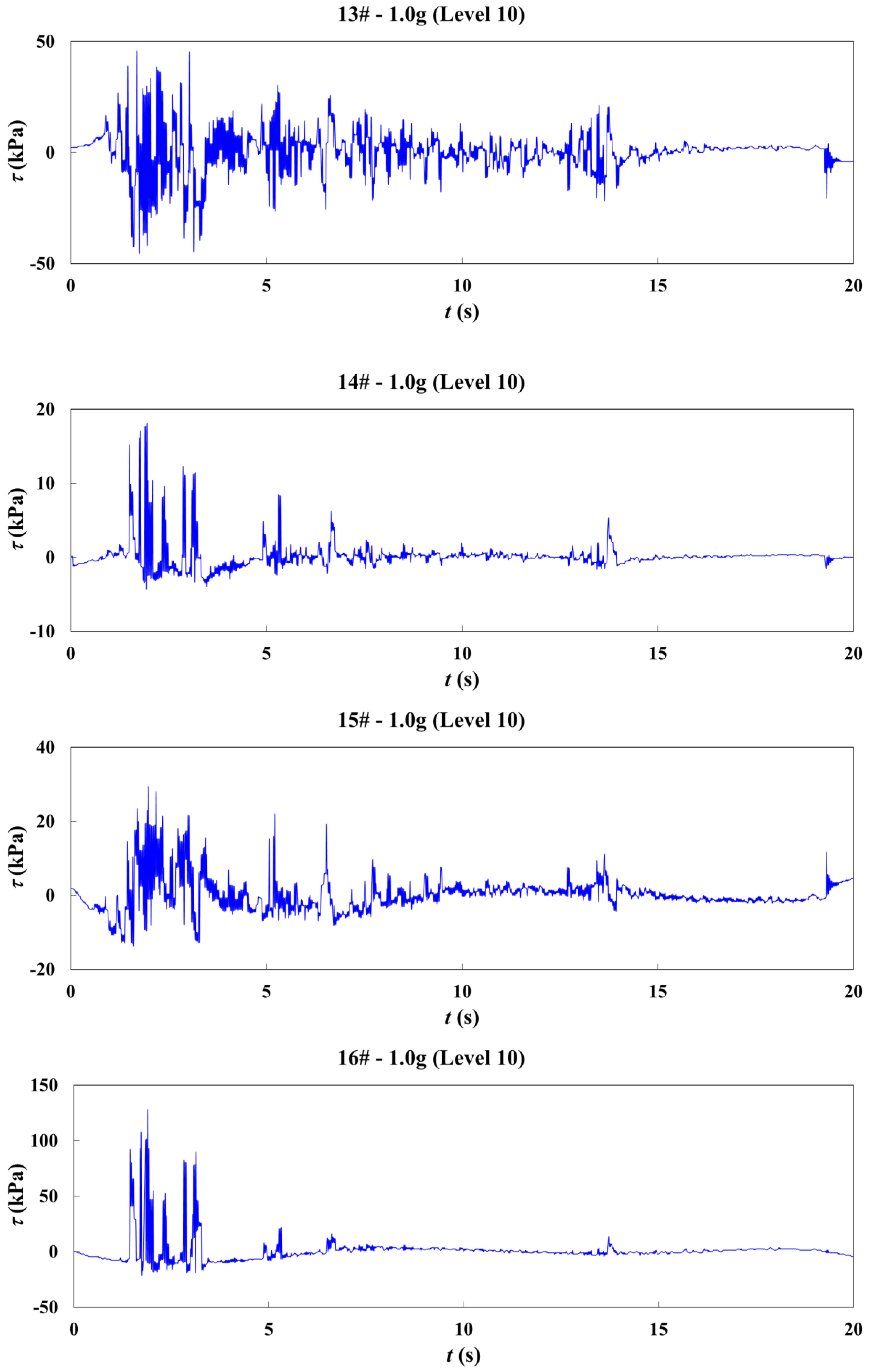
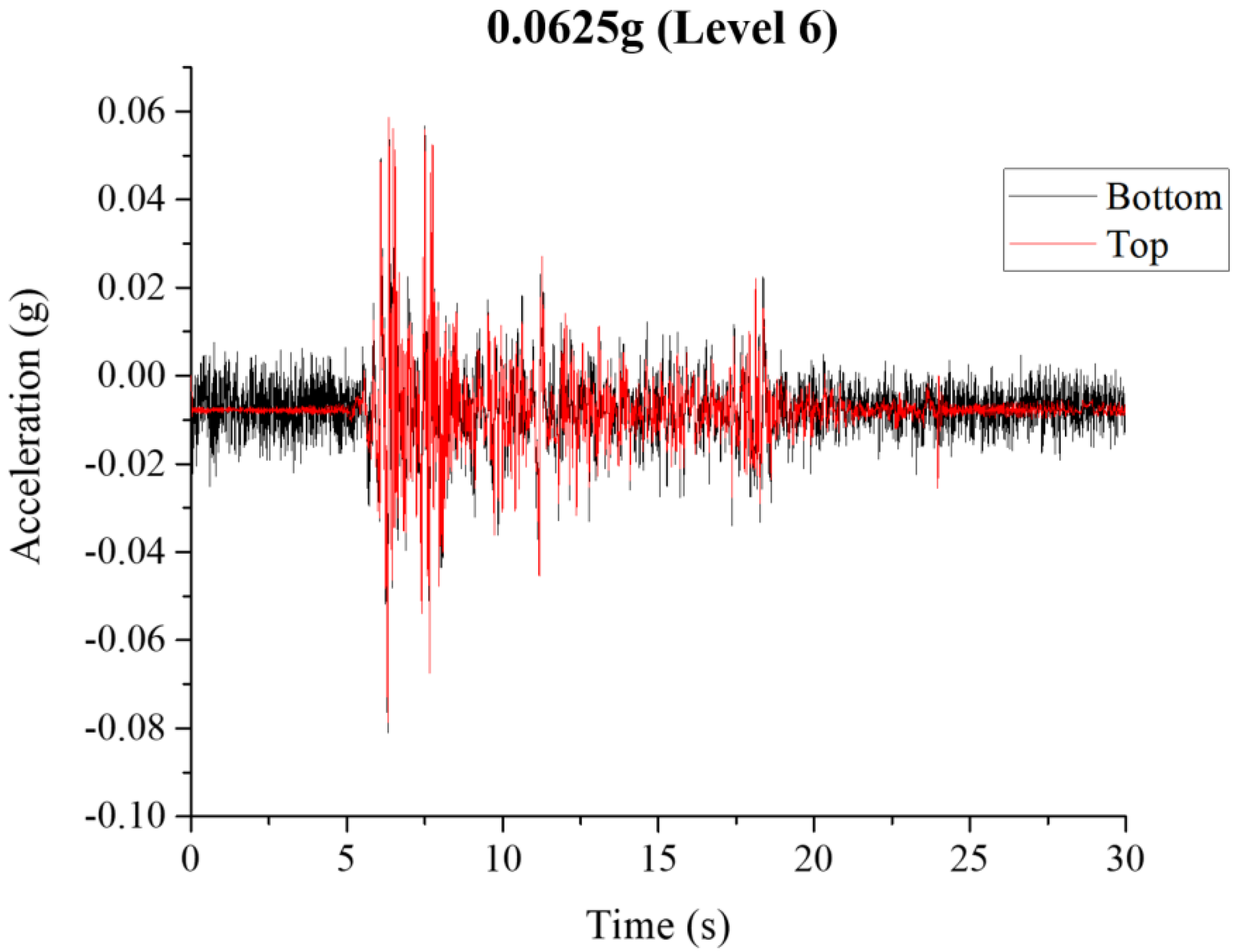
2.4. Experiment Results

To quantitatively describe the safety of the rock mass, the material strength, failure criteria, and stress–strain state of the rock mass during the earthquake process need to be considered. The failure form of the rock mass during the earthquake process is usually shear failure, and the mechanical behavior of all the materials in these experiments can be explained by the Mohr–Coulomb criterium from the previous study; thus, the Mohr–Coulomb criterium is used as the failure criterium:
τ = c + σ t a n φ
τ is the shear stress, c is the cohesion, φ is the internal friction angle, and σ is the normal stress. The values of c and φ are material-dependent and can be determined through shear tests.
To provide a more accurate description of the seismic safety of the distributed underground water reservoir between the upper and lower rock layers in a coal mine, the safety factor k (the ratio of the shear bearing capacity of the rock mass to the actual shear force) is defined. The equation is shown below:
k = τ p τ a = c + σ a t a n φ τ a
τp is the shear-bearing capacity, τa is the actual shear force, and σ is the actual normal stress. The larger the value of k, the safer the measurement point is.
Figure 7 and Figure 8 display the time–history curves of shear stress on underground reservoir model, corresponding to the ten measuring points measuring by acceleration sensors and strain sensors. According to these time–history curves of shear stress, the dynamic response mechanism of the dam can be deeply studied. It can be seen from the figures that the data of each monitoring point are normal and show strong regularity, indicating that the experimental results are quite reliable.
Additionally, utilizing the experimental data, Figure 9 illustrates the safety levels at different measuring points under various earthquake intensity conditions. From the figure, it is seen that under the action of seismic loads, the shear changes along the monitoring surface as follows:
(1) As we descend from the upper 2-2 coal seam, the shear force increases, and the potential failure area is near the 5-2 coal seam.
(2) Near the lower water reservoir, the shear force is larger, and the potential failure area spreads from the vicinity of the water reservoir to the area far away from the water reservoir.
(3) Due to the constraint of the model box boundary, the safety levels of the 14th measuring point and the 18th measuring point near the sides of the model box are relatively high. Under the action of an eight-degree seismic load, the safety level of the 17th measuring point is 2.19. Under the action of a nine-degree seismic load, the safety level of the 17th measuring point is 1.12, the safety level of the 15th measuring point is 1.24, and the safety level of the 16th measuring point is 2.25. Under the action of a 10-degree seismic load, the safety level of the 15th measuring point is 1.006, and the safety levels of the 16th and 17th measuring points are less than 1.0.

3. Numerical Simulation

In order to analyze the reasonable safe distance between the upper and lower layers of the water reservoir under seismic conditions, the stress variation law of rock layers between the upper and lower layers during lower coal excavation was studied, and numerical dynamic analysis was conducted to verify the results through a physical model test.

3.1. Basic Theory

3.1.1. Seismic Dynamic Equation

In the analysis of the seismic safety of distributed underground water reservoir rock mass, it is necessary to establish the seismic dynamic equation. Taking the lower coal floor as the reference system, when a single particle m undergoes a horizontal motion component on the lower coal floor during an earthquake, it is subjected to elastic restoring force S and damping force R. The elastic restoring force S is a force that returns the particle m from the vibration position to the equilibrium position. Its value is proportional to the relative displacement x(t) of the particle m; that is, S = −k·x(t), where k is the force applied to the particle when it produces a unit horizontal displacement.
In the process of structural vibration, the vibration will gradually decay due to friction at the connection between structural components and supports, the resistance of external media, the material’s non-elastic deformation, and energy dissipation through foundations. The force that causes the structural vibration to decay is usually called damping force. Generally, it is assumed that the damping force is proportional to velocity; that is, R = c x ˙ ( t ) , where c is the damping coefficient.
Under the action of an earthquake, the absolute acceleration of a particle is x ¨ ( t ) + x ¨ g ( t ) . According to Newton’s second law, the motion differential equation of the particle under the action of an earthquake load can be obtained by transforming the equation [31]:
m x ¨ ( t ) + c x ˙ ( t ) + k x ( t ) = m x ¨ g ( t )
From this, the displacement of a multi-particle system can be derived. The elastic restoring force Si of a multi-particle system during an earthquake is:
S i = ( k i 1 x 1 + k i 2 x 2 + + k i n x n ) = r = 1 n k i r x r
S i = ( k i 1 x 1 + k i 2 x 2 + + k i n x n ) = r = 1 n k i r x r , ( i = 1 , 2 , , n )
where k i r is the elastic reaction force generated at the i point when a unit displacement is produced at the r point and other points are stationary.
The damping force Ri of the multi-particle system during an earthquake is [26,27]:
R i = ( c i 1 x ˙ 1 + c i 2 x ˙ 2 + + c i n x ˙ n ) = r = 1 n c i r x ˙ r ,       ( i = 1 , 2 , , n )
where the damping force generated at the i point when a unit velocity is produced at the r point and other points are stationary.
According to Newton’s second law, the motion differential equation of the multi-particle system can be obtained [31,32]:
m i ( x ¨ 0 + x ¨ i ) = r = 1 n k i r x r r = 1 n c i r x ˙ r ,       ( i = 1 , 2 , , n )
That is:
[ m ] { X ¨ } + [ c ] { X ˙ } + [ k ] { X } = x ¨ 0 [ m ] { l }
where [ m ] is the mass matrix, { X ¨ } is the acceleration vector, [ c ] is the damping matrix, { X ˙ } is the velocity vector, [ k ] is the stiffness matrix, { X } is the displacement vector, and { l } is the unit vector.

3.1.2. Dynamic Analysis Equation

In the analysis of seismic safety of distributed underground water reservoir rock mass, it is necessary to establish the seismic dynamic equation. The lower coal floor–lower underground water reservoir–interlayer rock mass–upper underground water reservoir–overlying rock mass is treated as a coordinated system, and the whole system is analyzed using three-dimensional unit analysis. The basic assumptions and boundary conditions in the calculation process are as follows:
① The coal and rock layers and the underground water reservoir are assumed to be uniform and continuous everywhere, and it is believed that the mechanical properties of any unit in the dam and foundation can reflect the overall mechanical properties, without considering the discontinuity between various parts caused by the construction of the underground water reservoir.
② The rock mass of each coal and rock layer has reached a long-term natural stable state, and the new deformation caused by self-weight is ignored, so the rock mass is modeled as a massless foundation to eliminate the effect of wave propagation and avoid artificial amplification.
③ The top surface of the model is unconstrained, and the constraints on the other four sides and the base are determined according to the situation.
Based on the above assumptions, the motion Equation (7) can be transformed into [33,34]:
[ m ] { X ¨ } + [ c ] { X ˙ } + [ k ] { X } = [ m ] { R } X ¨ g ( t )
where the damping matrix [ c ] is the energy dissipation mechanism during vibration process, { R } is the influence coefficient vector, which represents the displacement linked to the base unit displacement of the system’s degrees of freedom, and X ¨ g ( t ) is the seismic acceleration time history imported to the distributed underground water reservoir model. Considering that { X ¨ } , { X ˙ } and { X } are the relative acceleration, relative velocity, and relative displacement vectors of the system, respectively, we have:
{ X ¨ } = t { X ˙ }
{ X ¨ } = 2 t 2 { X }
The process of dynamic analysis of the distributed underground water reservoir rock mass between upper and lower layers is the process of solving the equation in Equation (8).

3.1.3. Time History Analysis

The differential equation described in Equation (8) is complex, and it is difficult to obtain an analytical solution, so numerical methods are usually used to solve it. Considering that X ¨ g ( t ) in Equation (8) (seismic acceleration time history) depends on time, numerical methods usually decompose the earthquake waves into multiple sub-intervals according to the given seismic acceleration record, substitute them into the vibration differential equation of the distributed underground water reservoir structure, and apply the step-by-step implicit integration method to analyze the structural visco-elastic dynamic response to solve the internal forces and deformations of the rock mass structure at each moment. This method is called time history analysis.
Specifically: Assume that the state of the system at time t n is known, and the relative acceleration, relative velocity, and relative displacement vectors of each particle are { X ¨ ( t n ) } , { X ˙ ( t n ) } , and { X ( t n ) } , respectively. Using these as initial conditions, according to the predetermined boundary conditions, the seismic load from t n time to t n + 1 , and the motion differential Equation (8), the system state at time can be calculated. By repeating this calculation, the dynamic state of the system at each time period can be solved one by one, thereby obtaining the dynamic response of the distributed underground water reservoir system during the entire earthquake period.

3.2. Numerical Model

The specific steps of numerical simulation analysis are as follows.

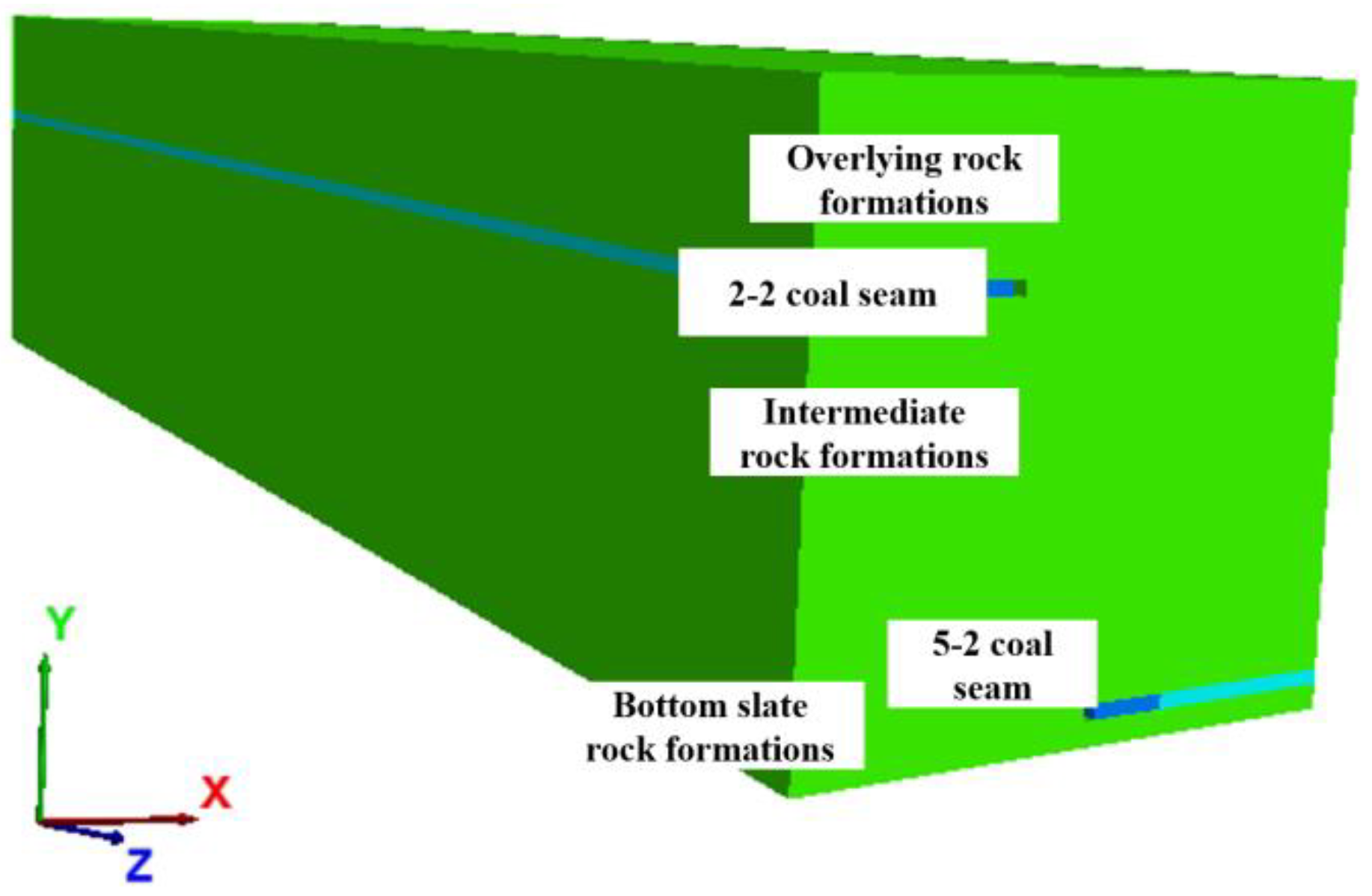
3.2.1. Numerical Model

Through analysis of the geological environment of the distributed underground reservoir, the model is divided into several computational units according to simulation requirements. In this simulation, 20,000 to 30,000 grid units were divided to construct the numerical model. The seismic safety numerical model and grid division of the upper and lower layers of the underground reservoir are shown in Figure 10.

3.2.2. Boundary Condition

Based on engineering practice, the boundary conditions of the model are defined before and after, left and right. The boundary conditions of this model are set as follows:
① Apply viscous boundary conditions to the front, back, left, and right boundaries of the model to absorb incident waves;
② Set a viscous boundary at the bottom boundary of the model;
③ The top boundary of the model is a free boundary, and the overlying rock layer is subjected to self-weight stress.

3.2.3. Mechanical Parameters

The selected parameters are as follows: the elastic modulus of the coal seam is 26 MPa, the compressive strength is 1.76 kPa, the tensile strength is 26 kPa, the Poisson’s ratio is 0.25, the unit weight is 2.6 kN/m3, the cohesive force is 2 kPa, and the internal friction angle is 38°; the elastic modulus of the overlying rock layer and the bottom plate is 26 Mpa, the tensile strength is 2.98 kPa, the compressive strength is 78 kPa, the Poisson’s ratio is 0.18, the unit weight is 5.2 kN/m3, the cohesive force is 14 kPa, and the internal friction angle is 38°.

3.2.4. Simulating the Shear Stress Variation with Different Seismic Intensity Conditions

Analysis shows that the damage caused during an earthquake is generally due to shear failure, so only shear strain is considered in the numerical dynamic analysis. In the simulation experiment, the static load of the model is its self-weight, and the dynamic load is the earthquake action. EI-Centro seismic waves are used as the earthquake wave. The seismic wave load intensities for the model experiment are set to 6 degrees, 7 degrees, 8 degrees, 9 degrees, and 10 degrees, with corresponding peak accelerations of 0.0625 g, 0.125 g, 0.25 g, 0.5 g, and 1.0 g, respectively. Initially, static analysis is performed, and based on the static field, dynamic simulation analysis is conducted.

3.2.5. Analyzing the Seismic Safety of the Rock Mass between the Upper and Lower Layers of the Reservoir

To analyze the distribution law of shear stress in the rock mass between the upper and lower layers of the distributed underground reservoir provides a technical reference for determining the reasonable safety distance between the upper and lower layers of the reservoir.

3.3. Analysis of Simulation Results

Damage that occurs during earthquakes is generally caused by shear failure. Therefore, shear force is the main consideration in stress analysis. Figure 11 shows the distribution of the maximum shear force (τyz) in the upper and lower reservoir model for earthquake intensities of 6 degrees (peak acceleration 0.0625 g) and 10 degrees (peak acceleration 1.0 g). The numerical results indicate that the trend of the maximum shear stress in the middle rock layer is basically the same under different seismic intensity conditions. The farther away from the lower coal excavation position, the smaller the shear stress in the middle rock layer. Moreover, the closer to the excavation face, the faster the decrease in shear stress. The peak value of the maximum shear stress occurs near the 5-2 coal excavation position, and as it moves away from the 5-2 coal excavation position, the shear stress gradually decreases. Within the safety distance selected for this numerical simulation (60 cm), the shear stress in the rock layer below the 2-2 coal goaf is less than one eighth of the maximum shear stress, indicating that the excavation of the 5-2 coal has a relatively small impact on the upper underground reservoir at this safety distance.

4. Conclusions

This paper explores the innovative underground water structure of distributed coal mine water reservoirs. Utilizing the Daliuta Coal Mine distributed underground water reservoir in China as the engineering prototype and considering the construction of multiple underground water reservoirs within the same mining area and their distribution across different coal seams, the study employs dynamic similarity model testing and numerical simulation methods to investigate and analyze the safety of constructing and operating distributed underground water reservoirs under extreme conditions, such as mine-induced seismic activity or earthquakes. The following conclusions were drawn:
  • For the seismic safety of the rock mass between the upper and lower layers of the distributed underground reservoir in coal mines, conducting physical model tests alone allows for the analysis of dynamic response behavior at a limited number of monitoring points, which makes it challenging to reflect the overall seismic safety performance of the reservoir. Conversely, conducting dynamic numerical analysis alone poses challenges regarding constitutive relationship and dynamic boundary conditions, making it difficult to evaluate the accuracy and reliability of the simulation results. Therefore, it is essential to undertake comprehensive research using both dynamic model tests and numerical analysis for mutual verification. The study demonstrates that the dynamic response behavior obtained from both methods is relatively consistent.
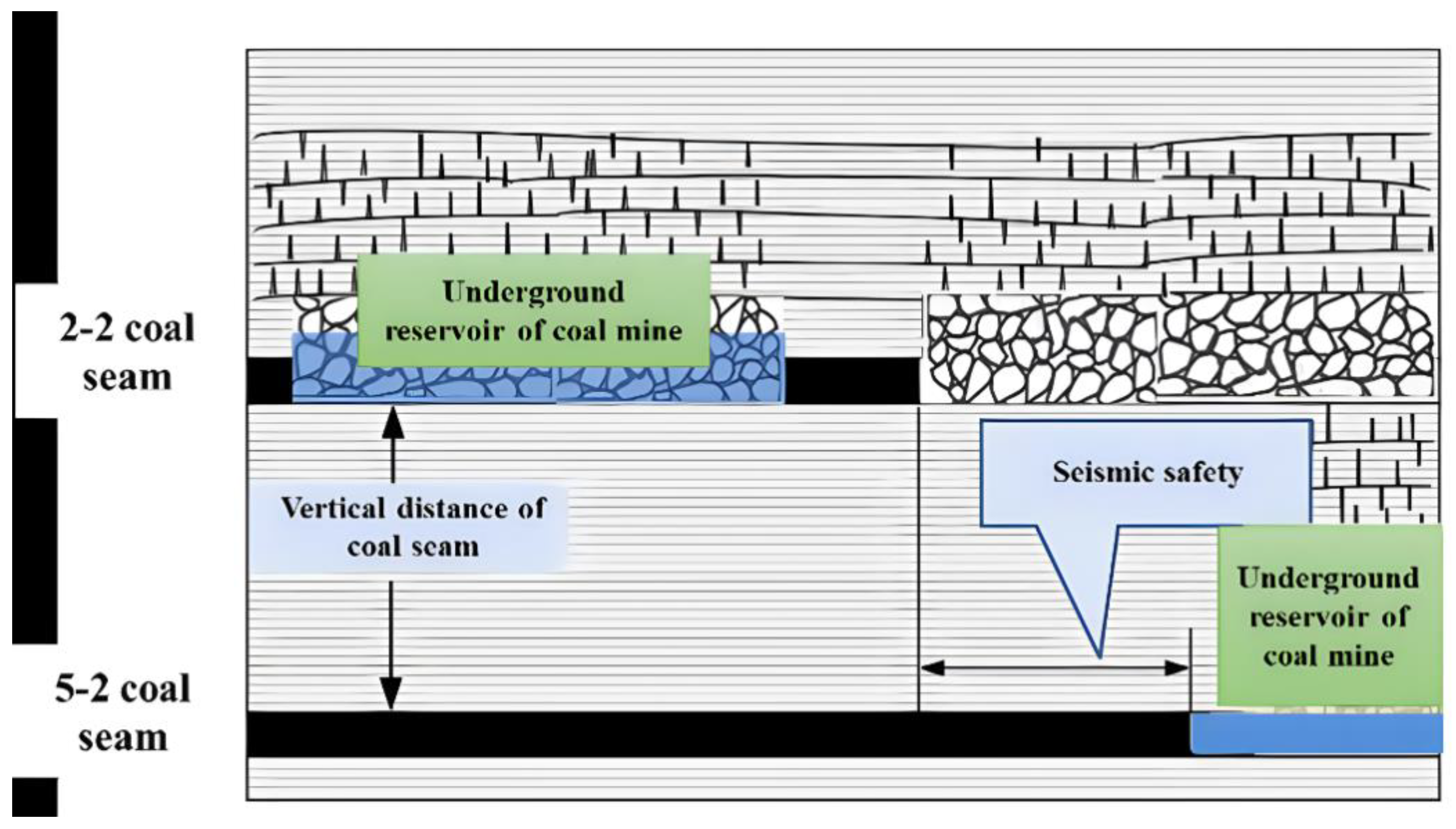
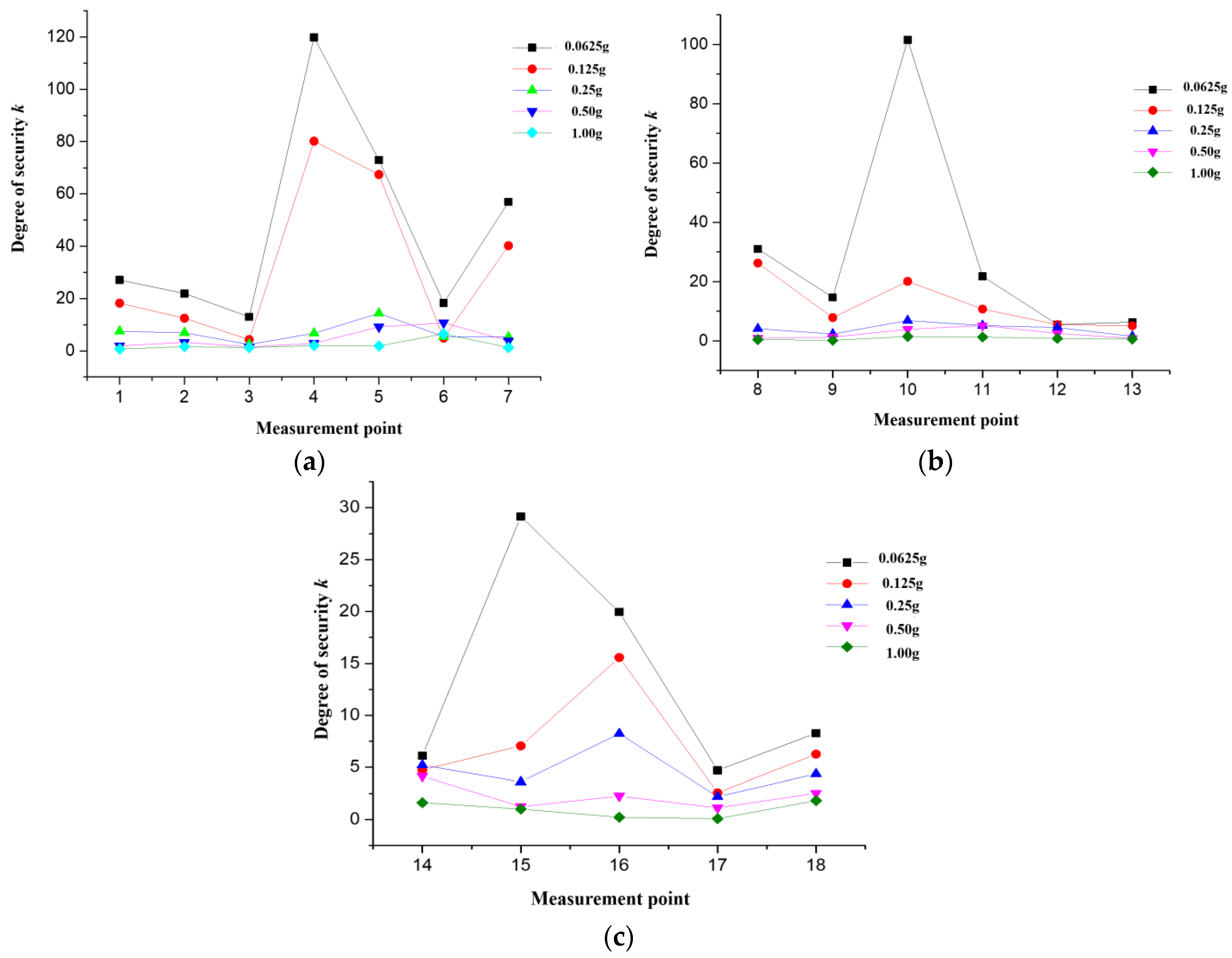
  • The variation trend of the maximum shear stress in the middle rock layer remains consistent under different seismic intensity conditions: the farther away from the lower coal excavation position, the lower the shear stress in the middle rock layer, and the closer to the excavation position, the faster the decrease in shear stress. Therefore, the larger the horizontal safety distance between the upper and lower reservoirs, the smaller the influence between the two reservoirs.
  • For the Daliuta Coal Mine, the horizontal safety distance between the upper and lower reservoirs under a seismic load of eight degrees should be greater than 190 m to ensure their safety. Under a seismic load of nine degrees, the horizontal safety distance should be greater than 230 m to ensure their safety. Under a seismic load of 10 degrees, the safety distance between the upper and lower reservoirs should be greater than 270 m to ensure their safety.

Author Contributions

Conceptualization, Y.Z. and Z.C. (Zhiguo Cao); methodology, Z.C. (Zhaofei Chu) and L.W.; Model test, E.Z., Y.Z. and S.L.; writing—original draft preparation, Y.Z. and Z.C. (Zhiguo Cao); writing—review and editing, Y.Z. and Z.C. (Zhaofei Chu); supervision, E.Z., Z.C. (Zhiguo Cao) and L.W.; funding acquisition, Y.Z. and Z.C. (Zhaofei Chu). All authors have read and agreed to the published version of the manuscript.

Funding

The research work was financially supported by the Science and technology innovation project of China Shenhua Co., Ltd. (Grant No. SHGF-16-19) and by Open Fund of State Key Laboratory of Water Resource Protection and Utilization in Coal Mining (Grant No. WPUKFJJ2019-05), for which the authors are grateful.

Data Availability Statement

Data are contained within the article.

Conflicts of Interest

The authors declare no conflict of interest.

References

  1. Gu, D.; Yan, Y.; Zhang, Y. Experimental Study and Numerical Simulation for Dynamic Response of Coal Mine Underground Reservoir. J. China Coal Soc. 2016, 41, 9. [Google Scholar]
  2. Liu, C.S.; Liang, L.L.; Wang, L.; Zheng, S. Allocation and Utilization of Coal Mine Water for Ecological Protection of Lakes in Semi-Arid Area of China. Sustainability 2022, 14, 9042. [Google Scholar] [CrossRef]
  3. Peng, S. Coal Resources and Water Resources—A Strategic Study on China Coal Clean, Efficient and Sustainable Development; Science Press: Beijing, China, 2014. [Google Scholar]
  4. Liu, Q.H.; Xue, Y.B.; Ma, D.; Li, Q. Failure Characteristics of the Water-Resisting Coal Pillar under Stress-Seepage Coupling and Determination of Reasonable Coal Pillar Width. Water 2023, 15, 1002. [Google Scholar] [CrossRef]
  5. Feng, H.B.; Zhou, J.W.; Chai, B.; Zhou, A.G.; Li, J.Z.; Zhu, H.H.; Chen, H.N.; Su, D.H. Groundwater environmental risk assessment of abandoned coal mine in each phase of the mine life cycle: A case study of Hongshan coal mine, North China. Environ. Sci. Pollut. R 2020, 27, 42001–42021. [Google Scholar] [CrossRef]
  6. Gu, D.; Zhang, Y.; Cao, Z. Technical progress of water resource protection and utilization by coal mining in China. Coal Sci. Technol. 2016, 44, 7. [Google Scholar]
  7. Han, P.H.; Zhang, C.; Wang, W. Failure analysis of coal pillars and gateroads in longwall faces under the mining-water invasion coupling effect. Eng. Fail. Anal. 2022, 131, 105912. [Google Scholar] [CrossRef]
  8. Wang, Q.Q.; Han, Y.B.; Zhao, L.G.; Li, W.P. Water Abundance Evaluation of Aquifer Using GA-SVR-BP: A Case Study in the Hongliulin Coal Mine, China. Water 2023, 15, 3204. [Google Scholar] [CrossRef]
  9. Chu, Z.; Wu, Z.; Liu, B. Mechanical response of inclined TBM tunnel due to drainage settlement of deep sandstone aquifer. Tunn. Undergr. Space Technol. 2022, 122, 1425144. [Google Scholar] [CrossRef]
  10. Chu, Z.; Wu, Z.; Liu, Q.; Weng, L.; Xu, X.; Wu, K.; Sun, Z. Viscos-elastic-plastic solution for deep buried tunnels considering tunnel face effect and sequential installation of double linings. Comput. Geotech. 2024, 165, 105930. [Google Scholar] [CrossRef]
  11. Aksoy, C.O.; Kucuk, K.; Uyar, G.G. Safety pillar design for main galleries in multi-slice longwall top coal caving method. Int. J. Oil Gas Coal Technol. 2015, 9, 329–347. [Google Scholar] [CrossRef]
  12. Chang, J.Y.; Ahn, S.C.; Lee, J.S.; Kim, J.Y.; Jung, A.R.; Park, J.; Choi, J.W.; Yu, S.D. Exposure assessment for the abandoned metal mine area contaminated by arsenic. Environ. Geochem. Health 2019, 41, 2443–2458. [Google Scholar] [CrossRef] [PubMed]
  13. Pujades, E.; Willems, T.; Bodeux, S.; Orban, P.; Dassargues, A. Underground pumped storage hydroelectricity using abandoned works (deep mines or open pits) and the impact on groundwater flow. Hydrogeol. J. 2016, 24, 1531–1546. [Google Scholar] [CrossRef]
  14. Zhang, Z.X.; Guo, Q.; Liu, W. Evaluation of Long-Term Tightness of the Coal Pillar Dam of Underground Reservoir and Protection Countermeasures. Energies 2022, 15, 7229. [Google Scholar] [CrossRef]
  15. Wang, W.A.; Yao, Q.L.; Xu, Q.; Chen, X.Y.; Liu, H.Y.; Li, X.H. Experimental Study on the Evolution Law of Coal Mine Underground Reservoir Water Storage Space under the Disturbance and Water-Rock Interaction Effect. Minerals 2022, 12, 1491. [Google Scholar] [CrossRef]
  16. Zhu, W.B.; Yu, S.C.; Xuan, D.Y.; Shan, Z.J.; Xu, J.L. Experimental study on excavating strip coal pillars using caving zone backfill technology. Arab. J. Geosci. 2018, 11, 554. [Google Scholar] [CrossRef]
  17. Zhu, M.T.; Li, B.; Liu, G. Groundwater risk assessment of abandoned mines based on pressure-state-response-The example of an abandoned mine in southwest China. Energy Rep. 2022, 8, 10728–10740. [Google Scholar] [CrossRef]
  18. Pitilakis, K.; Tsinidis, G. Performance and Seismic Design of Underground Structures. Earthq. Geotech. Eng. Des. 2014, 28, 279–340. [Google Scholar]
  19. Rapantova, N.; Licbinska, M.; Babka, O.; Grmela, A.; Pospisil, P. Impact of uranium mines closure and abandonment on groundwater quality. Environ. Sci. Pollut. R 2013, 20, 7590–7602. [Google Scholar] [CrossRef] [PubMed]
  20. Shi, X.M.; Liu, B.G.; Tannant, D.; Qi, Y. Influence of consolidation settlement on the stability of inclined TBM tunnels in a coal mine. Tunn. Undergr. Space Technol. 2017, 69, 64–71. [Google Scholar] [CrossRef]
  21. Galav, A.; Singh, G.S.P.; Sharma, S.K. Hydro-Mechanically Coupled Numerical Modelling of Protective Water Barrier Pillars in Underground Coal Mines in India. Mine Water Environ. 2023, 42, 418–440. [Google Scholar] [CrossRef]
  22. Wu, K.; Zheng, X.M.; Zhao, N.N.; Shao, Z.S. Effect of compressible layer on time-dependent behaviour of soft-rock large deformation tunnels revealed by mathematical analytical method. Appl. Math. Model 2024, 126, 457–481. [Google Scholar] [CrossRef]
  23. Kumar, R.; Das, A.J.; Mandal, P.K.; Bhattacharjee, R.; Tewari, S. Probabilistic stability analysis of failed and stable cases of coal pillars. Int. J. Rock Mech. Min. Sci. 2021, 144, 104810. [Google Scholar] [CrossRef]
  24. Kumar, R.; Mandal, P.K.; Ghosh, N.; Das, A.J.; Banerjee, G. Design of Stable Parallelepiped Coal Pillars Considering Geotechnical Uncertainties. Rock Mech. Rock Eng. 2023, 56, 6581–6602. [Google Scholar] [CrossRef]
  25. Prassetyo, S.H.; Irnawan, M.A.; Simangunsong, G.M.; Wattimena, R.K.; Arif, I.; Rai, M.A. New coal pillar strength formulae considering the effect of interface friction. Int. J. Rock Mech. Min. Sci. 2019, 123, 104102. [Google Scholar] [CrossRef]
  26. Davoodi, M.; Jafari, M.K.; Sadrolddini, S.M.A. Effect of multi-support excitation on seismic response of embankment dams. Int. J. Civ. Eng. 2013, 11, 19–28. [Google Scholar]
  27. Moradloo, A.J.; Naiji, A. Effects of rotational components of earthquake on seismic response of arch concrete dams. Earthq. Eng. Eng. Vib. 2020, 19, 349–362. [Google Scholar] [CrossRef]
  28. Tarinejad, R.; Fatehi, R.; Harichandran, R.S. Response of an arch dam to non-uniform excitation generated by a seismic wave scattering model. Soil Dyn. Earthq. Eng. 2013, 52, 40–54. [Google Scholar] [CrossRef]
  29. Zhang, J.W.; Li, M.C.; Han, S. Seismic Analysis of Gravity Dam-Layered Foundation System Subjected to Earthquakes with Arbitrary Incident Angles. Int. J. Geomech. 2022, 22, 04021279. [Google Scholar] [CrossRef]
  30. Jianming, Z.; Xiaosheng, L.; Yusheng, Y. Criteria for seismic safety evaluation and maximum aseismic capability of high concrete face rockfill dams. Chin. J. Geotech. Eng. 2015, 37, 8. [Google Scholar]
  31. Zhu, F.; Wang, J.T.; Jin, F.; Lu, L.Q. Control performance comparison between tuned liquid damper and tuned liquid column damper using real-time hybrid simulation. Earthq. Eng. Eng. Vib. 2019, 18, 695–701. [Google Scholar]
  32. Hashash, Y.M.A.; Park, D.; Yao, J.I.C. Ovaling deformations of circular tunnels under seismic loading, an update on seismic design and analysis of underground structures. Tunn. Undergr. Space Technol. 2005, 20, 435–441. [Google Scholar] [CrossRef]
  33. Shen, X.; Yuan, D.J.; Lin, X.T.; Chen, X.S.; Peng, Y.S. Evaluation and prediction of earth pressure balance shield (EPBS) performance in complex rock strata: A case study in Dalian. J. Rock. Mech. Geotech. 2023, 15, 1491–1505. [Google Scholar] [CrossRef]
  34. González-Quirós, A.; Fernández-Alvarez, J.P. Conceptualization and finite element groundwater flow modeling of a flooded underground mine reservoir in the Asturian Coal Basin, Spain. J. Hydrol. 2019, 578, 124036. [Google Scholar] [CrossRef]
Figure 1. Schematic of distributed coal mine underground reservoir.
Water 16 00366 g001
Figure 2. Schematic of the spatial location of the upper and lower coal mine reservoirs.
Water 16 00366 g002
Figure 3. Schematic of similar material model.
Water 16 00366 g003
Figure 4. Schematic of strain rosette position. Red numbers in the figure represent strain monitoring points.
Water 16 00366 g004
Figure 5. Similar material model pouring process: (a) the floor and the interlaminar rock pouring, (b) strain rosettes layout, where the red numbers represent strain monitoring points, (c) coal seam 2-2 pouring, and (d) similar material model poured overlying strata.
Water 16 00366 g005
Figure 6. Time–history curve of seismic acceleration.
Water 16 00366 g006
Figure 7. Time–history curves of shear stress on underground reservoir model for all measuring points 1#–18#.
Water 16 00366 g007aWater 16 00366 g007bWater 16 00366 g007cWater 16 00366 g007dWater 16 00366 g007e
Figure 8. Time–history curve of the acceleration in the underground reservoir model.
Water 16 00366 g008
Figure 9. The safety of measuring points in interlaminar rock with different seismic intensity. (a) Measuring points #1–7; (b) measuring points #8–13; (c) measuring points #14–18.
Water 16 00366 g009
Figure 10. The numerical model of the distributed coal mine underground reservoir.
Water 16 00366 g010
Figure 11. The maximum strain of underground reservoir model with different seismic intensity. (a) Peak acceleration = 0.0625 g. (b) Peak acceleration = 0.0625 g.
Water 16 00366 g011
Table 1. Physical and mechanical parameters of overlying strata.
Rock TypeDensity/Kg·m−3Compressive Strength/MPaCohesion/MPaInternal Friction/°Elastic Modulus/GPaPoisson’s RatioThickness/M
wind-blown sand 1700120.0220120.338
siltstone 245041.837.073813.20.1812
fine sandstone 241035.046.463813.160.25
siltstone 245041.837.073813.20.187
fine sandstone 241035.046.463813.160.26
siltstone 245041.837.073813.20.184
fine sandstone 241035.046.463813.160.218
siltstone 245041.837.073813.20.182
2-2 coal 132013.5130130.265
siltstone mudstone 245041.837.073813.20.182
5-2 coal243045.945.552910.090.153
wind-blown sand 125611.602.3140.216.90.206
Disclaimer/Publisher’s Note: The statements, opinions and data contained in all publications are solely those of the individual author(s) and contributor(s) and not of MDPI and/or the editor(s). MDPI and/or the editor(s) disclaim responsibility for any injury to people or property resulting from any ideas, methods, instructions or products referred to in the content.

