Article

Salt Drainage Efficiency and Anti-Clogging Effects of Subsurface Pipes Wrapped with Geotextiles

1
Institute of Agricultural Resources and Environment, Ningxia Academy of Agriculture and Forestry Sciences, Yinchuan 750002, China
2
Station of Observation and Experiment National Agricultural Environment in Yinchuan, Yinchuan 750002, China
*
Author to whom correspondence should be addressed.
Water 2024, 16(10), 1392; https://doi.org/10.3390/w16101392
Submission received: 25 March 2024 / Revised: 6 May 2024 / Accepted: 10 May 2024 / Published: 14 May 2024
(This article belongs to the Special Issue Effects of Hydrology on Soil Erosion and Soil Conservation)

Abstract

:
Subsurface drainage pipes covered with filters and geotextiles are the key to preventing clogging and ensuring efficient drainage. To improve the salt discharge efficiency of these subsurface drainage pipes, different layers of geotextiles were set outside the pipes with the aid of uniform gravel filters. This paper reports our findings from laboratory simulation of subsurface drainage pipes and experiments. The study examined the influence of different layers of geotextiles on the drainage efficiency, salt discharge effects of subsurface drainage pipes, and the effect of superimposed geotextiles on the salt drainage efficiency as well as the anti-clogging effect of subsurface drainage pipes. The results are as follows: (1) The geotextile and filter material wrapped around the subsurface pipe facilitated the movement of water towards the subsurface pipe, which could promote the salt discharge of the subsurface pipe. However, in the single leaching experiment, the reduction in soil pH was not significant for different scenarios. (2) The salt removal rate of the geotextile-wrapped subsurface pipes was more than 95%. The salt removal rate of the double-layer geotextile scenario was the highest (96.7%), and the total salt content of soil profiles was 8.3% and 31.3% lower than those of the single-layer and triple-layer geotextile scenarios, respectively. The drainage efficiency of the double-layer geotextile scenario was the highest, and the salt distribution in the 0–60 cm profile was relatively uniform, ranging from 2.3 to 3.0 g∙kg−1. (3) The clogging in the triple-layer geotextile scenario was caused by the geotextile, i.e., a dense filter cake layer formed on the surface of the geotextile. The clogging in the single-layer and double-layer geotextile scenarios was the clogging of the geotextile itself, i.e., soil particles retained in the fiber structure of geotextiles. (4) In the case of the single-layer and double-layer geotextile scenarios, the soil particles failed to completely clog the selected geotextiles, and there were still a large number of pores retained. The double-layer geotextiles integrate filtration, clogging prevention, and drainage promotion to provide the best salt drainage with the subsurface pipe. This study reveals the influence of the filter on soil water salt and salt discharge and provides a theoretical explanation and technical justification for the application of the subsurface pipes salt discharge technology in saline soil ameliorate.

1. Introduction

Soil salinization is one of the factors that causes soil degradation, reduces food production, and affects the ecological health of agriculture and forestry [1]. It is reported that more than 100 countries and regions worldwide are affected by soil salinization, with an area of 950 million hectares [2,3]. More than half of the arable land will experience varying degrees of salinization by the middle of this century [4]. Saline soils in China cover an area of nearly 100 million hectares and are mainly distributed in arid inland regions of north China, northeast China, coastal regions, and northwest China [5]. Ningxia Hui Autonomous Region is located in the arid inland regions of northwest China. The Yellow River irrigation region in the north is obviously characterized by high evaporation and low precipitation, a flat and low-lying terrain, high groundwater levels, and salt migration, which result in severe soil salinization. The area of saline-alkali-cultivated land is about 1.4 × 10⁶ ha, accounting for 32.5% of the total arable land area in the Yellow River irrigation area of Ningxia [6]. Rational utilization of saline-alkali land can serve as an alternative for land resources for the sustainable development of agriculture and forestry, which is of great significance for holding the red line of 1.2 billion ha of arable land. In the meantime, the utilization of saline-alkali land plays an important role in improving the ecological environment in the middle and upper reaches of the Yellow River, as well as promoting ecological protection and high-quality development in the Yellow River Basin.
An efficient irrigation and drainage system can remove solutes and act as a barrier for preventing salinity and alkalinity [7,8]. As an underground drainage facility, the subsurface drainage pipe (SDP) has the advantages of high efficiency, water conservation, and land conservation, which is conducive to mechanized operations [9,10,11]. SDP can reduce soil salinity while controlling the groundwater level, overcoming the drawbacks of traditional ameliorate that cannot discharge salts from the soil [12,13]. In 1980, the technology of subsurface pipes was introduced in Ningxia Hui Autonomous Region. After years of application, the area of subsurface pipes in the field has reached 1.7 × 10⁵ ha, and the subsurface pipes have become the preferred solution for addressing the salinization hazards in the Yinbei Irrigation District [14]. Subsurface drainage systems promote salt discharge by influencing soil-saturated hydraulic conductivity and effective porosity [15]. Climate and soil conditions are the main factors that determine the spacing and depth of underground pipes [16]. Numerous scholars have proposed the depth, spacing, and diameter of subsurface pipes under different desalination standards [17,18]. However, the clogging of drainage pipes by soil particles, plant roots, and solutes during the operation of saline-alkali land can restrict efficient salt discharge by the subsurface pipes. In the process of long-term application of subsurface pipe drainage, mechanical clogging caused by soil particles, chemical clogging caused by oxidative precipitation of ions by ions being oxidized and precipitated, and biological clogging caused by microbial microorganism activities during the long-term operation of subsurface pipe drainage will cause the blockage of subsurface pipes, which is a non-negligible problem that cannot be ignored, and has become one of the main factors restricting the long-term salt discharge of subsurface pipes. It is also a problem that needs to be solved in for the promotion of subsurface pipe salt discharge technology. Coarse sand or clay loam can form a natural anti-filter layer, which is less likely to clog the filter material outside the subsurface pipes. Soils with a low clay content and a higher finer particle content are more likely to clog the drainage pipe [19]. The soil in the Yinbei region of Ningxia is mostly composed of sticky clay loam or loam clay, which is more likely to cause clogging. At present, subsurface drainage mainly relies on external geotextiles and filter materials such as sand, gravel, and straw to prevent or alleviate siltation. External filter materials can form a highly permeable layer around the drainage pipes to promote drainage and salt discharge [14]. A filter made of porous sand gravels, straw, and furnace slag installed above the subsurface pipes can restrict the movement of soil particles and screen and retain coarse particles around the filter to form a highly permeable stable zone. Geotextiles have a three-dimensional fibrous net structure, which is permeable and filtering, and during water flow, they screen the nearby soil particles and induce the formation of a highly permeable soil skeleton above the geotextile, resulting in a good filtration effect. The geotextile wrapped outside the subsurface pipes needs to satisfy three principles of good filtration, strong permeability, and the fact that it is not easy to block. The main considerations include the O90/d90 value (O90 is the pore diameter of filter materials, of which 90% is smaller than this value; d90 is the size of the soil particles, of which 90% is smaller than this value, and should satisfy O90/d90 ≥ 1.0), suitable permeability coefficient, and thickness of geotextile [19]. In addition, geotextiles can be pre-wrapped, which facilitates mechanized construction and is widely used for on-site subsurface pipes [20]. Superposition treatment of geotextiles can enhance the filtration effect and achieve a high soil retention rate. How to use scientific and reasonable filter materials wrapped around the subsurface pipes to fully utilize the anti-filter effect of filter materials and to ensure efficient salt discharge of subsurface pipe are the bottlenecks that need to be overcome urgently to eliminate the salt alkali barriers.
The wrapped filter materials are the key factor affecting the efficient drainage of subsurface pipes. Field investigations were conducted to investigate the anti-clogging effects of different filter materials of subsurface pipes. There are reports on the influence of different geotextile specifications on salt discharge and clogging in subsurface pipes [21,22]. Geotextiles with a three-dimensional fibrous network structure need to be further investigated to determine whether they can increase filtration and ensure efficient salt discharge in subsurface pipes by stacking. For this purpose, this study systematically evaluated the impact of the wrapped geotextile on the salt discharge efficiency and anti-siltation effect of subsurface pipes by using a self-designed laboratory simulation device for subsurface pipe drainage. The surface and internal structures of geotextiles were observed by using an electron microscope, and the impact of geotextile stacking on salt discharge and the anti-clogging effects of subsurface pipes were revealed. The findings provide a scientific basis for optimizing the engineering parameters of subsurface drainage pipes and improving the quality of low-lying saline soil.

2. Materials and Methods

2.1. Tested Soils

The experiment was conducted from May to September 2022. The soil used for experiments was taken from salt wasteland in Haiyan Village, Yanzidun Township, Huinong District, Shizuishan City, Ningxia (39°03’ N, 106°54’ E). This region belongs to the Yinbei Irrigation Area of the Ningxia Hui Autonomous Region, with low-lying terrain, high groundwater levels, and severe soil salinization. The region has a temperate continental climate and is an arid semi-desert saline land in the middle and upper reaches of the Yellow River. The annual average precipitation and evaporation are 173 mm and 1755 mm, respectively. The precipitation is sparse and unevenly distributed and is mainly concentrated between July and September. The depth of groundwater ranges from 1.3 m to 2.0 m. Soil samples were collected from 0 to 60 cm below the ground surface, with a high salt content of more than 70 g∙kg−1 and a pH below 8.43 ± 0.01 (Table 1). The 0–60 cm soil layer contained 9.0% clay particles (<0.002 mm), 38.8% silt sand particles (0.002–0.02 mm), and 52.2% sand particles (0.02–2.0 mm). The soil d90 values for the 0–20 cm, 20–40 cm, and 40–60 cm soil layers were 87.5 ± 4.3 μm, 95.4 ± 2.9 μm, and 99.6 ± 1.1 μm, respectively. d90 is the size of the soil particle, of which 90% are smaller than this value. The ratio of soil clay content to silt content was 0.23, which was lower than 0.5 [19]. The soil was loamy soil and had low cohesion. It is not easy to form a natural filter layer around the subsurface drainage pipes, leading to a high possibility of clogging. Subsurface drainage pipes that are not wrapped with geotextiles and filter materials are susceptible to mechanical clogging, which affects the normal operation of the drainage system.

2.2. Simulation Device for Subsurface Pipe Drainage

The referenced field project had a depth of 150 cm, a filter material thickness of 30 cm, a backfill soil layer thickness of 112.5 cm, and an outer diameter of subsurface pipe of 7.5 cm. With reference to the laboratory subsurface pipe drainages, simulated experiments designed by Tao et al. (2016) with a 1:3 scale ratio were adopted for experiments [22]. The designed laboratory simulation test device for subsurface pipe drainage consisted of a water supply system, a seepage box, and a collector box. The seepage box was 1.0 m long, 0.6 m wide, and 0.8 m high (Figure 1). To prevent preferential flow along the wall during the leaching process, the inner layer of the testing device was polished with sandpaper. The depth of the subsurface pipe in the experimental device was 50 cm, and the thickness of the filter material was 10 cm. The thickness of the backfill soil was 37.5 cm, and the diameter of the subsurface pipe was 2.5 cm. The thickness of the organic glass around the seepage box was 8 mm. An overflow port was installed 5 cm away from the top of the seepage box to avoid excessive water accumulation during the leaching process, and three sampling ports were installed on the box wall.

2.3. Experiment Design and Process

Geotextiles have a three-dimensional fibrous network structure made of short fiber polypropylene material with a fluffy structure and large porosity, which makes them permeable and filterable (Figure 2). To clarify the impact of geotextile stacking on the salt discharge and anti-clogging effects of subsurface pipes, experiments were conducted in the Yanzidun Township from May to September 2022 based on a self-designed laboratory simulation device for subsurface pipe drainage. The geotextiles wrapped around the subsurface pipes were designed with three different scenarios: single-layer geotextile (T1), double-layer geotextiles (T2), and triple-layer geotextiles (T3), with three replicates for each scenario. The geotextile used in the experiment was a short fiber needle-punched nonwoven geotextile made of polypropylene, with a specification of 100 g∙m−2, a density of 1.35 ± 0.12 g∙cm−3, a thickness of 0.75 ± 0.04 mm, a breaking strength of 2.5 ± 0.13 kN∙m−1, a tearing strength of 0.08 ± 0.01 kN, a vertical permeability coefficient of 0.06 ± 0.01 cm∙s−1, and an equivalent diameter O90 of 0.12 ± 0.01 mm. The geotextile used in the experiment has good alkaline resistance and can be used below pH 9.0. The nonwoven geotextile is a flake with good water collection and drainage performance.
Plant residues and debris, such as gravel, were removed from soil samples. The samples were then air-dried, ground, and passed through a 2 mm sieve. A 5 cm thick layer of sand was placed on the bottom, and a subsurface pipe wrapped with geotextile was placed on the quartz sand filter layer. The whole area percent of the subsurface pipe was 5%. The soil was loaded into the test box layer by layer and compacted layer by layer to a thickness of 60 cm. Thereafter, it was left overnight to establish a water content equilibrium. The leaching quota was calculated based on the formula suggested by Hu et al. (2010) [23]. The calculated leaching quota was 6750 m3∙hm−2, which was equivalent to 0.4 m3 per seepage box. The leaching process began on 19 May 2022 at 9:00 AM. Multiple leaching was accomplished using the water injection method. The depth of the water layer during the leaching process was maintained at 10 cm, and the water source was municipal tap water. The conductivity of the leaching water was 0.55 mS∙cm−1.

2.4. Sample Collection and Measurement

The anti-clogging effect of the geotextile in the subsurface pipe was demonstrated by the weight of soil lost in the seepage box, as well as the amount and rate of clogging. Three geotextile-treated subsurface pipes were weighed prior to the experiment. During the experiment, the drained water and mineralization of the subsurface pipes were regularly monitored every day, and the mineralization of the leaching water was regularly measured. Upon completion of the experiment (i.e., when the drainage of the subsurface pipe ceased), the soil profile was manually excavated, and samples were taken from both sides of the subsurface pipes to measure the moisture content and salinity. The geotextile wrapped outside the subsurface pipe was weighed, and the geotextile samples were taken from the upstream surface for observation using a scanning electron microscope. Soil profile samples were collected using an auger, and samples were taken every 20 cm from the surface to the top of the filter material directly above the subsurface pipe. The samples were taken at distances of 5 cm, 15 cm, and 25 cm from the center of the subsurface pipe, and each soil sample was repeated three times.

2.5. Measurement and Methods

The moisture content of the soil was determined by the drying method. The supernatant was fully shaken at a soil-to-water ratio of 1:2.5, and pH was measured using the Mettler Toledo S220 multi-parameter tester (METTLER TOLEDO, Switzerland. We bought it in Shanghai, China. Microtrac S3000, York, PA, USA. Hitachi TM4000plus, Tokyo, Japan). The supernatant was fully shaken at a soil-to-water ratio of 1:5 and was measured using a DDS-307A soil conductivity meter, which was converted to the total salt content [24]. The mechanical composition was measured by the laser particle size analyzer (Microtrac S3000). The water filling amount was measured by a flow meter, and mineralization was measured by a conductivity meter. The drainage duration was measured by a stopwatch, and the drainage volume of subsurface pipes was measured by measuring cylinders. The structures of geotextiles were observed using scanning electron microscopy (Hitachi TM4000plus). The quality of soil loss was the weight of soil lost through geotextiles after the completion of experiments. The clogging amount refers to the soil mass adsorbed on the upstream surface of the geotextile and retained inside the geotextile after the completion of experiments. The clogging rate was the ratio of the amount of clogging to the original quality of the geotextile.

2.6. Calculation Formulae

The formulae for calculating the drainage rate (v), drainage efficiency (Rw), salt discharge rate (Rs), desalination rate (LR), discharge to removal ratio (R), and clogging rate (w) of subsurface pipes are as follows [25]:
v = Q T A
where v is the drainage rate of the subsurface pipe, with a unit of cm∙h−1; Q is the drainage volume of the subsurface pipe within a certain period of time, with a unit of cm3; T is the drainage duration, with a unit of h; and A is the cross-sectional area of the seepage channel, with a unit of cm2.
R w = Q w L × 100 %
where Rw is the drainage efficiency of the subsurface pipe, with a unit of %; Qw is the total amount of drainage from the subsurface pipe, with a unit of cm3; and L is the total amount of leaching water, with a unit of cm3.
R s = Q s S 0 + L s × 100 %
where Rs represents the salt discharge rate of the subsurface pipe, with a unit of %; Qs is the total amount of salt discharged from the subsurface pipe, with a unit of kg; S0 is the initial total salt content of the soil, with a unit of kg; and Ls is the salt content of the leaching water, with a unit of kg.
L R = S 0 S t S 0 × 100 %
where LR is the soil leaching desalination rate, with a unit of %; S0 is the total salt content of the soil before leaching, with a unit of kg; and St is the total salt content of the soil after leaching, with a unit of kg.
R = R s L R
where R is the discharge rate of the subsurface pipe; R s is the salt discharge rate of the subsurface pipe; and L R is the soil leaching desalination rate.
w = W t W 0 W 0 × 100 %
where w is the siltation rate, with a unit of %; Wt is the weight of the geotextile after the experiment, with a unit of g; and W0 is the initial weight of the geotextile, with a unit of g.

2.7. Data Processing and Analysis

Microsoft Excel 2010 was used for data processing, while Surfer 10 was utilized to plot nephrograms. SPSS 19.0 software to perform the significance test and correlation analysis.

3. Results

3.1. Soil Moisture Distribution under Different Scenarios

The measurements showed that the soil moisture contents in the depth of 0–60 cm ranged from 15.5 ± 0.45% to 20.5 ± 0.55% for scenario T1, from 13.5 ± 0.20% to 20.0 ± 0.75% for scenario T2, and from 19.0 ± 0.33% to 21.4 ± 0.88% for scenario T3, respectively (Figure 3). The soil moisture content of the three scenarios follows a decreasing trend as the soil depth increases. The moisture content in the region near the subsurface pipe was significantly higher than that in the upper soil layer. The geotextile and filter material wrapped around the subsurface pipe was conducive to the movement of water toward the subsurface pipe. The soil moisture content of scenario T3 in the depth of 0–60 cm was significantly higher than those of scenarios T1 and T2. There was a small difference in the soil moisture content between scenarios T1 and T2 in the depths of 20–40 cm and 40–60 cm. Scenario T2 had double-layer geotextiles, and the soil moisture content in the depth of 0–60 cm was the lowest among the three scenarios. The stacking of geotextiles allowed for a richer three-dimensional structure and enhanced the effects of permeability and filterability, especially in the triple-layer geotextile scenario.

3.2. Soil Salt Distribution under Different Scenarios

The salt content of the tested soils ranged from 71.17 to 99.86 g∙kg−1, and the salt content in the soil profiles of the three scenarios after leaching was below 4.8 ± 0.55 g∙kg−1 (Figure 4). The salinity of the soils in the three scenarios experienced an increasing trend as the soil depth increased. Scenario T1 had a soil profile salinity of less than 2.0 ± 0.22 g∙kg−1 in the 0–30 cm soil layer, which was the lowest among the three scenarios. The accumulated salinity was below 40 cm in the soil layer. The soil salt content in the 0–60 cm profile of scenario T3 was higher than those of scenarios T2 and T3. The soil salt content below 40 cm was higher than 3.9 ± 0.15 g∙kg−1. The salt distribution in the 0–60 cm profile of scenario T2 was relatively uniform, ranging from 2.3 to 3.0 g∙kg−1. Compared with the scenarios of the single-layer geotextile and the triple-layer geotextile, the salt leaching of scenario double-layer geotextile was more uniform. Therefore, moderate geotextile stacking has better effects on permeability and filterability, which could promote uniform salt leaching in the soil profile.

3.3. Analysis of the Effect of Soil Salt Leaching and Alkali Reduction under Different Scenarios

Before the experiment, the pH values of the tested soils at 0–20 cm, 20–40 cm, and 40–60 cm were 8.43 ± 0.01, 8.42 ± 0.01, and 8.42 ± 0.01, respectively, which indicated that the soil pH distributions were relatively uniform. The pH values in the depth of 0–60 cm varied from 8.29 to 8.36, from 8.30 to 8.36, and from 8.35 to 8.39 for scenarios T1, T2, and T3, respectively. In the single leaching experiment, the reduction in soil pH was not significant for different scenarios, and the difference among the three scenarios was not significant (Table 2).
Before the experiment, the salt content of the tested soils exceeded 70 g∙kg−1, and the total salt content in the 0–60 cm depth was 33.22 ± 10.02 kg. After the leaching experiments, the soil salt contents of the three scenarios were all less than 4.1 ± 0.10 g∙kg−1. The soil salt contents of scenarios T1, T2, and T3 were between 1.8–3.1 g∙kg−1, 2.3–3.0 g∙kg−1, and 3.6–4.1 g∙kg−1, respectively. After the leaching experiments, the total soil salt contents in the seepage boxes for scenarios T1, T2, and T3 were 1.2 ± 0.06 kg, 1.1 ± 0.06 kg, and 1.6 ± 0.02 kg, respectively, which were 96.4%, 96.7%, and 95.2% lower than those before the experiment. After the leaching experiments, the soil salinity at 0–20 cm of scenario T1 was 1.8 ± 0.17 g∙kg−1, which was the lowest among the three scenarios. The highest soil salinity was observed in scenario T3, which was significantly higher than those in scenarios T2 and T3 (p ˂ 0.05). The soil salinity of scenarios T1 and T2 at 20–40 cm was lower than 2.4 g∙kg−1, which was significantly lower than that of scenario T3 (p ˂ 0.05). The soil salinity at 40–60 cm of scenarios T1 and T2 was significantly lower than that of scenario T3 (p ˂ 0.05). The total soil salt content of scenario T2 was the lowest, at 8.3% and 31.3% lower than that of scenarios T1 and T3, respectively. The double-layer geotextile scenario had the best salt leaching effect because of the reasonable geotextile stacking.

3.4. Analysis of Salt Leaching Efficiency under Different Scenarios

The observations from the experiments are listed in Table 3. It can be seen that scenario T2 has the highest values for the majority of the parameters except for the drainage rate (v). The drainage rate (v) was the highest in scenario T1, and the drainage rates of scenarios T1 and T2 were significantly higher than that of scenario T3 (p ˂ 0.05). Scenario T2 had the highest drainage efficiency (Rw) and salt discharge rate (RS), with a subsurface pipe drainage ratio of 0.98, which offered the best salt discharge effect. Scenario T1 had a higher initial drainage rate (v), but the drainage efficiency (Rw) was lower than the other scenarios. Scenario T3 had the lowest drainage rate (v) and salt discharge rate (Rs) among the three scenarios. This was because the thickness of the triple-layer geotextile wrapped around the subsurface pipe was large, which increased the difficulty of water passage and affected the drainage effect, leading to a poor salt removal effect of the subsurface pipe. Scenario T2 promoted the drainage of subsurface pipe and had a removal rate of 0.98, which provided the best salt removal effect.

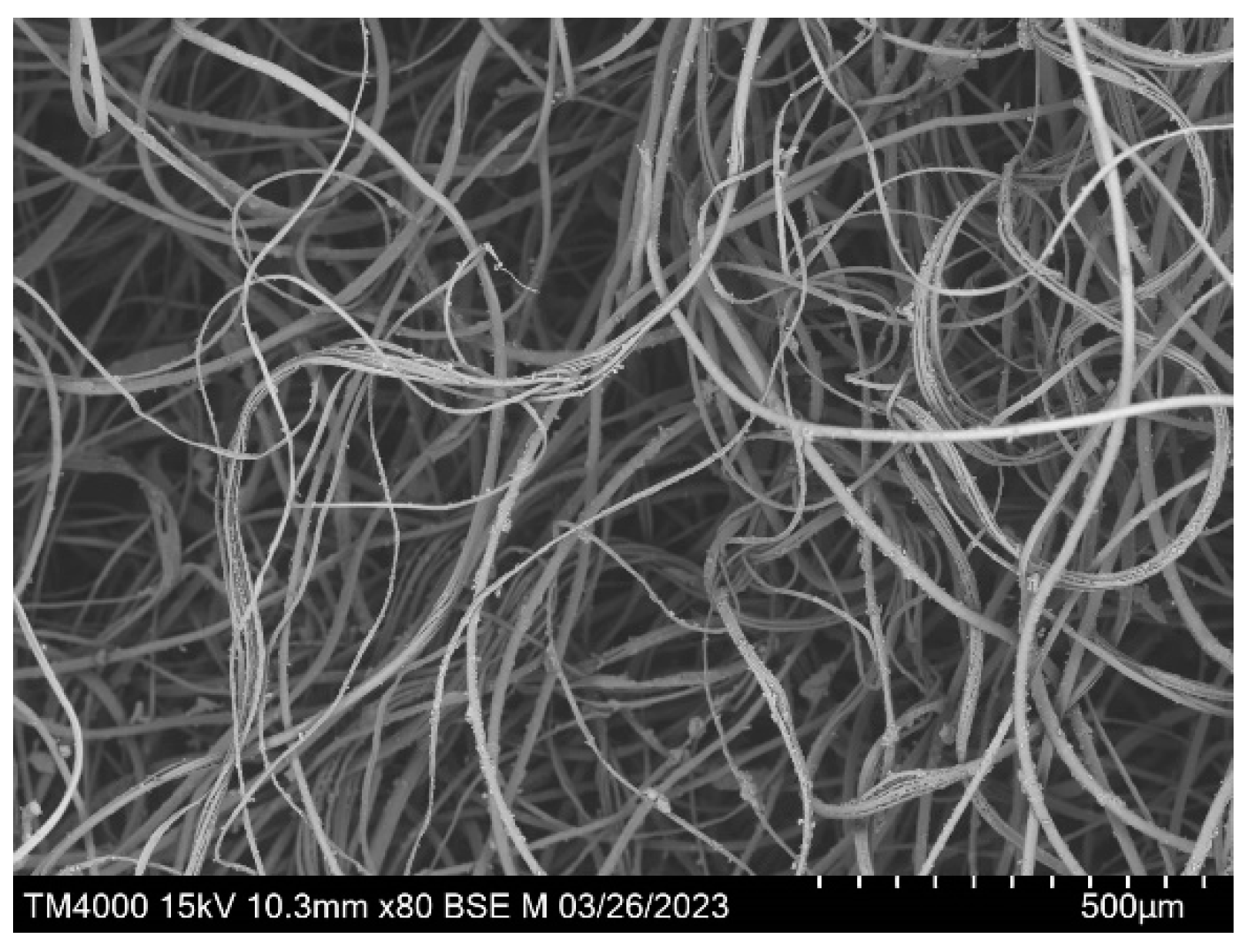
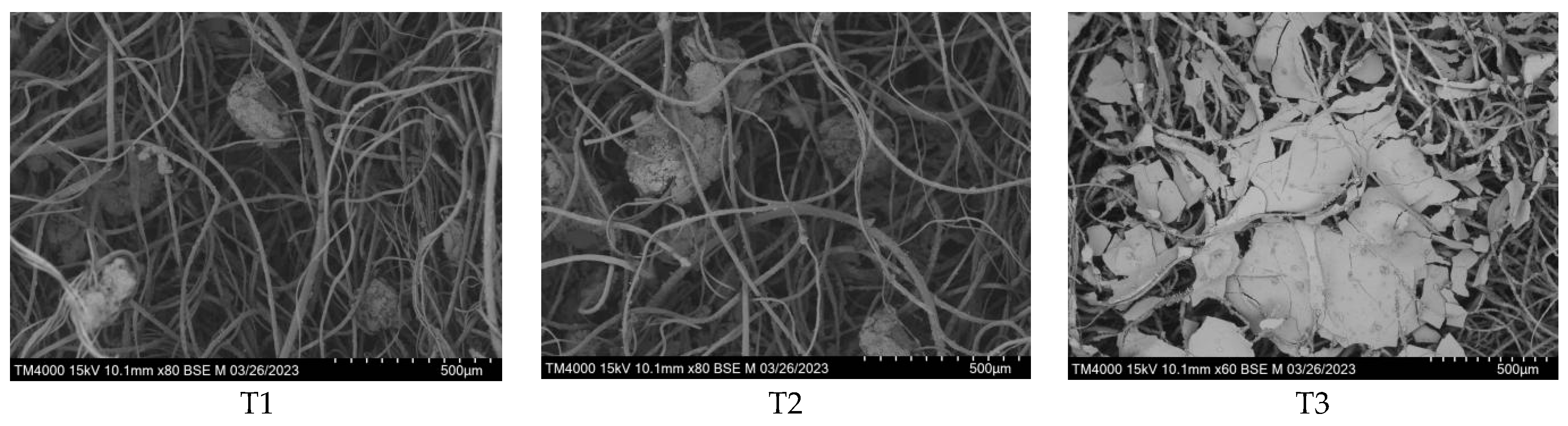
3.5. Geotextile Clogging and Soil Retention Effect

Particles in soils were entrained by moving water, with some particles passing through the geotextile into the drainage system while others intercepted by the geotextile. The soil particles were generally intercepted through clogging and siltation. Scenarios T1 and T2 resulted in siltation inside the geotextile, where fine soil particles were trapped in the fiber structure of the geotextile, leading to a decrease in its permeable area. Scenario T3 resulted in clogging of the upstream surface of the geotextile, where soil particles were collected to form a layer of low-permeability filter cakes on the upstream surface of the geotextile (Figure 5). Observations of the surface and internal structures of geotextile using scanning electron microscopy revealed that the pores of the geotextile wrapped around the subsurface pipe were clogged or blocked by the clusters composed of fine soil particles, resulting in a decrease in the water surface of the geotextile. Scenario T3 resulted in the formation of a clear and dense filter cake layer on the upstream surface. In scenarios T1 and T2, soil particles did not completely block the geotextile, and a large number of pores were present.
The results from the experiments are listed in Table 4, which demonstrates the differences between the scenarios and, more importantly, the order of the clogging rates was T3 > T2 > T1. After one drainage experiment, the soil loss of all three scenarios exceeded 110 g, with the highest soil loss in scenario T1 and the lowest in scenario T3. Soil loss in scenario T3 was 35.3% and 17.0% lower than those in scenarios T1 and T2, respectively, with significant pairwise differences among the three scenarios (p ˂ 0.05). All three scenarios exhibited different forms of clogging. Scenario T1 had the lowest clogging rate, which was 7.0% and 18.5% lower than those of scenarios T2 and T3, respectively. The triple-layer geotextile had a strong interception effect with less soil loss. However, it failed to form a permeable coarse particle skeleton above the subsurface pipe, and more particles would accumulate above the geotextile, making it easier to form filter cakes. The soil retention and anti-clogging effects of geotextile-wrapped subsurface pipe were closely related to the particle content of the tested soil and the thickness of the geotextiles. A smaller thickness would cause some soil particles to form a natural filter layer, pass through the geotextile, and enter the drainage pipes, resulting in soil losses. In practice, the soil particles lost during the drainage process would lead to sedimentation within the drainage pipe. The single-layer geotextile in scenario T1 had a small thickness, and the fine soil particles were prone to enter the drainage pipes through the geotextile, leading to soil losses. The triple-layer geotextile in scenario T3 had a larger thickness, which had a good soil retention effect. However, it was prone to forming a dense filter cake layer on the upstream surface, resulting in a high siltation rate. The double-layer geotextile in scenario T2 considered both soil retention and anti-clogging effects.

4. Discussion

Within a short period of time after drainage onset, soil particles undergo directional migration. Fine particles in the soil gradually move downwards to fill pores by the drag of water flow. The redistribution of particles leads to continuous compaction of the soil, and the drainage flow rate of the subsurface pipe gradually decreases. In severe cases, it can lead to the loss of drainage function [22].
The interior of geotextile is a fibrous network with many small pores that can form flow channels and block the passage of soil particles. The larger the equivalent pore size of geotextiles, the greater the soil loss. The smaller the thickness, the stronger the interception ability of soil. The stacking of geotextiles can improve the interception and particle-screening ability of soil. The geotextile wrapped around the subsurface pipe is used to screen nearby soil particles under the action of water flow. Large particles are intercepted and gradually accumulate outside to form a soil-permeable skeleton with high permeability, inducing the formation of a natural filter layer in the soil above [26,27].
The research found that geotextiles with a thickness of 0.41 mm had a better permeability and anti-clogging ability than those with a thickness of 0.35 mm [28]. The clogging rate of thick geotextiles alone was 16% lower than that of thin geotextiles. Thin geotextiles not only experience significant clogging on their own but also have a tighter filter cake formed on the surface of the geotextile. Reasonable filter materials could promote the soil above the pipe to form the bridge, filter cake, and natural soil areas from bottom to top, forming a good filter structure. Geotextiles can increase the characteristic particle size (d90) value of the soil by more than 20% through particle screening, inducing the formation of a highly permeable soil skeleton on its surface [19]. However, the available study pointed out that the surface of spun-bonded polypropylene geotextiles had smooth surfaces and was prone to producing thin particles called “pancakes” after contact with the soil [29]. After long-term operation, the small particles in the soil accumulate in the filter layer, causing mechanical clogging and affecting the drainage effect of subsurface pipes. In this experiment, the scanning electron microscopy results showed that the utilization of triple-layer geotextile formed a significant filter cake layer on the upstream surface, and the presence of the filter cake layer continued to absorb smaller soil particles that moved with water. The thickness of the filter cake gradually increased over time, leading to a decrease in permeability. For the scenarios of single-layer and double-layer geotextile, the soil particles were trapped in the fiber structure of the geotextile. The soil particles did not completely block the geotextile, and there were still a large number of effective pores.
Subsurface pipes had a more significant effect on desalination of the upper soil layer in the field, which could reduce the spatial heterogeneity of soil salinity and promote the transformation of soil salinity from “high salinity heterogeneity” to “low salinity homogeneity” [12]. The results of this experiment also verified the conclusion that the soil desalination rate of the wrapped subsurface pipes exceeded 95%, and the desalination effect was significant. The soil salt content changed from surface aggregation to desalination. The pre-leaching water flow rate of the thin geotextile in this experiment was fast, and the salt leaching of the upper soil was adequate. However, the interception effect of the thin geotextile on soil particles was limited.
During water flow, soil particles were easily trapped in the geotextile or through the geotextile into the subsurface pipe. The distribution of soil particles in the fiber structure of the geotextile was not uniform. The thickness of the triple-layer geotextile scenario increased the difficulty for soil particles to pass through the geotextile, making it easier to form a filter cake layer on the upstream surface. This is also the main reason for the different soil moisture movements in the three scenarios. In the early stage of the single-layer geotextile scenario, the leaching water flow was faster due to the large pores of the single-layer geotextile and the high drainage rate in the early stage. Over time, a large amount of water carried sediment into the filter material, and soil particles could easily stay in the geotextile fiber structure and block it, reducing drainage and salt discharge rates in the later stage. The drainage rate of the triple-layer geotextile scenario was low, and the salt removal effect was poor. The double-layer geotextile integrated filtration, anti-clogging, and drainage promotion. The soil profile salt leaching was uniform, and the salt removal effect was the best.
The long-term operation of the subsurface pipe drainage in the field has obvious effects on controlling the groundwater level, reducing the salinity of groundwater, preventing the occurrence of soil secondary salinization, and improving the surface ecological environment. Small subsurface pipe spacing can weaken the spatial heterogeneity of soil salinity and increase the dissolved oxygen content in the soil water, but it can also lead to the loss of soil nutrients, especially nitrogen. Nitrogen loss in farmland is mainly total nitrogen, and the loss of ammonium nitrogen is small [30]. The study pointed out that a reasonable increase in the leaching rate could help enhance the salt removal effect of the subsurface pipes [25]. Since the simulation experiment was conducted in the open-air environment in summer, and the evaporation was large in summer in the northwest arid region, the water loss caused by evaporation during the waterlogging leaching process would lead to insufficient leaching water volume. In this experiment, the salt leaching effect of 0–20 cm soil was satisfactory, but the salt content of some soil layers in the profile exceeded 4 g∙kg−1, and the salt content did not leach to the expected value. Therefore, it is necessary to fully consider the water loss caused by evaporation during the summer waterlogging leaching process and then adjust the amount of leaching water to obtain the expected results.
To deal with the problem of soil salt easily migrating upward in arid areas, it is particularly important to increase the surface coverage. Dense planting of crops or surface covering with film can help to reduce surface evaporation [31]. With the advancement of high-standard farmland construction projects, drip irrigation combined with a subsurface pipe drainage system has been widely applied, and a subsurface pipe has played an important role in controlling groundwater levels. However, the amount of drip irrigation washing water is limited, especially in arid areas where precipitation is scarce and evaporation is large. Appropriate increase in the vertical porous flow pipes filled with straw or sand can contribute to the salt drainage effect of subsurface pipes [32].

5. Conclusions

The desalination rate of the outside geotextile-wrapped subsurface pipes exceeded 95%, and the desalination rate of the stacked geotextile double-layer scenario was the highest as the moderate geotextile stacking yielded better effects of permeability and filterability, which could promote salt leaching in soil profile. The total salt content of the soil profile was 8.3% and 31.3% lower than those of the single-layer and triple-layer geotextile scenarios, respectively. The removal ratio with the double-layer geotextile scenario was the highest, and the soil profile salt leaching was uniform. The clogging caused by the triple-layer geotextile scenario was caused by the geotextile because the large thickness increased the difficulty of water passage, which formed a dense filter cake layer on the upstream surface of the geotextile. The siltation caused by the single-layer and double-layer geotextile scenarios was due to the clogging of the geotextile itself. That is, soil particles were retained in the fiber structure of the geotextile, the soil particles did not completely block the pores of the geotextile, and there were still a large number of effective pores. The thickness of the double-layer geotextile was moderate enough to provide a suitable three-dimensional structure. It integrates the advantages of filtration, anti-clogging, and drainage promotion to provide the best salt discharge effect for the subsurface pipe. The study revealed the influence of wrapped geotextiles on the salt discharge efficiency and anti-clogging effect of subsurface pipes, which provides evidence for the application of subsurface pipe salt discharge technology to ameliorate saline soils.

Author Contributions

All authors contributed to the conception and design. X.W. and Y.Z. carried out the experimental design, investigation, formal analysis, and writing. L.F. and J.S. contributed to the review and editing. All authors have read and agreed to the published version of the manuscript.

Funding

This research was funded by the National Natural Science Foundation Project (42367043); the Chinese Academy of Sciences ‘Western Light’ talent training program ‘Western Young Scholars’ project; the National Key Research and Development Plan Project (2021YFD1900605-05); Agricultural Science and Technology Independent Innovation Project of Ningxia Hui Autonomous Region (NGSB-2021-11-03); and the Observation and Monitoring of Basic Long-Term Scientific and Technological Work in Agriculture (NAES091AE18).

Data Availability Statement

Data are contained within the article.

Conflicts of Interest

The authors declare no conflicts of interest.

References

  1. Tarolli, P.; Luo, J.; Park, E.; Barcaccia, G.; Masin, R. Soil salinization in agriculture: Mitigation and adaptation strategies combining nature-based solutions and bioengineering. iScience 2024, 27, 108830. [Google Scholar] [CrossRef] [PubMed]
  2. Cuevas, J.; Daliakopoulos, I.; Moral, F.; Hueso, J.; Tsanis, I. A review of soil-improving cropping systems for soil salinization. Agronomy 2019, 9, 295. [Google Scholar] [CrossRef]
  3. Minhas, P.; Ramos, T.; Ben, A.; Pereira, L. Coping with salinity in irrigated agriculture: Crop evapotranspiration and water management issues. Agric. Water Manag. 2020, 227, 105832. [Google Scholar] [CrossRef]
  4. James, O. History of the roles of gypsum in soil reclamation and establishment of SAR/EC water quality guidelines. In Proceedings of the First IUSS Conference on Sodic Soil Reclamation, Changchun, China, 10–12 May 2021. [Google Scholar]
  5. Yang, J.; Yao, R.; Wang, X.; Xie, W.; Zhang, X.; Zhu, W.; Zhang, L.; Sun, R. Research on Salt-affected Soils in China: History, Status Quo and Prospect. Acta Pedol. Sin. 2022, 59, 10–27. (In Chinese) [Google Scholar]
  6. Liu, T.; Wang, B.; Xiao, H.; Wang, R.; Yang, B.; Cao, Q.; Cao, Y. Differentially improved soil microenvironment and seedling growth of Amorpha fruticosa by plastic, sand and straw mulching in a saline wasteland in northwest China. Ecol. Eng. 2018, 122, 126–134. [Google Scholar] [CrossRef]
  7. Askri, B.; Khodmi, S.; Bouhlila, R. Impact of subsurface drainage system on waterlogged and saline soils in a Saharan palm grove. Catena 2022, 212, 106070. [Google Scholar] [CrossRef]
  8. Askar, M.; Youssef, M.; Chescheir, G.; Negm, L.; King, K.; Hesterberg, D.; Amoozegar, A.; Skaggs, R. DRAINMOD simulation of macropore flow at subsurface drained agricultural fields: Model modification and field testing. Agric. Water Manag. 2020, 242, 106401. [Google Scholar] [CrossRef]
  9. Ritzema, H.; Abdel-Dayem, S.; El-Atfy, H.; Nasralla, M.; Shaheen, H. Challenges in modernizing the subsurface drainage systems in Egypt. Agric. Water Manag. 2023, 288, 108484. [Google Scholar] [CrossRef]
  10. Soe, Y.; Shinogi, Y.; Taniguchi, T. Changes in Certain Paddy Soil Properties under Perforated Sheet Pipe as Subsurface Shallow Drainage. Jpn. Agric. Res. Q. JARQ 2022, 56, 59–66. [Google Scholar] [CrossRef]
  11. Heng, T.; Feng, G.; Yang, L.; He, X.; Yang, G.; Li, F.; Xu, X.; Feng, Y. Soil salt balance in a cotton field under drip irrigation and subsurface pipe drainage systems. Agron. J. 2021, 113, 4875–4888. [Google Scholar] [CrossRef]
  12. Acharya, U.; Chatterjee, A.; Daigh, A. Effect of Subsurface Drainage Spacing and Depth on Crop Yield. Agron. J. 2019, 111, 1675–1681. [Google Scholar] [CrossRef]
  13. Chen, G.; Wei, Z.; Liu, H. Study on Soil Desalination Process of Saline-Alkaline Grassland along the Yellow River in Western Inner Mongolia under Subsurface Drainage. Sustainability 2022, 14, 14494. [Google Scholar] [CrossRef]
  14. Rong, Z.; Wang, S.; Hao, R.; Hao, R.; Tao, Y. Permeability and anti-clogging performance of geotextile envelope material around subsurface drainage pipe in Yinbei Irrigation District in Ningxia. Trans. Chin. Soc. Agric. Eng. 2021, 37, 68–75. (In Chinese) [Google Scholar]
  15. Talukolaee, M.; Naftchali, A.; Parvariji, L.; Ahmadi, M. Investigating long-term effects of subsurface drainage on soil structure in paddy fields. Soil Tillage Res. 2018, 177, 155–160. [Google Scholar] [CrossRef]
  16. Mante, A.; Ranjan, R.; Bullock, P. Subsurface drainage for promoting soil strength for field operations in southern Manitoba. Soil Tillage Res. 2018, 184, 261–268. [Google Scholar] [CrossRef]
  17. Han, D.; Chen, C.; Wang, F.; Li, W.; Peng, H.; Jin, Q.; Bi, B.; Shaghaleh, H.; Hamoud, Y.A. Effects of Subsurface Pipe Drainage Spacing on Soil Salinity Movement in Jiangsu Coastal Reclamation Area. Sustainability 2023, 15, 13932. [Google Scholar] [CrossRef]
  18. Tian, F.; Miao, Q.; Shi, H.; Li, R.; Dou, X.; Duan, J.; Liu, J.; Feng, W. Study on Water and Salt Transport under Different Subsurface Pipe Arrangement Conditions in Severe Saline–Alkali Land in Hetao Irrigation District with DRAINMOD Model. Water 2023, 15, 3001. [Google Scholar] [CrossRef]
  19. Liu, W.; Luo, W.; Jia, Z.; Pan, Y.; Tang, S.; Yuan, H.; Li, S. Experimental study on geotextile envelope for subsurface drainage in Yellow River Delta. Trans. Chin. Soc. Agric. Eng. 2013, 29, 109–116. (In Chinese) [Google Scholar]
  20. Tian, F.; Shi, H.; Miao, Q.; Li, R.; Duan, J.; Dou, X.; Feng, W. Soil Water and Salt Transport in Severe Saline–Alkali Soil after Ditching under Subsurface Pipe Drainage Conditions. Agriculture 2023, 13, 2196. [Google Scholar] [CrossRef]
  21. Guo, C.; Wu, J.; Zhu, Y.; Lin, Z.; He, S.; Qian, Y.; Yang, H.; Li, H.; Wei, M. Influence of clogging substances on pore characteristics and permeability of geotextile envelopes of subsurface drainage pipes in arid areas. Geotext. Geomembr. 2020, 48, 735–746. [Google Scholar] [CrossRef]
  22. Tao, Y.; Wang, S.; Xu, D.; Zhai, X. Effect of Structure-type on Improved Subsurface Drainage Performance. Trans. Chin. Soc. Agric. Mach. 2016, 47, 113–118. (In Chinese) [Google Scholar]
  23. Hu, S.; Tian, C.; Song, Y. Calculation of salinity leaching quota based on saturated infiltration theroy. Acta Pedol. Sin. 2010, 47, 563–567. (In Chinese) [Google Scholar]
  24. Wang, X.; Sun, Z.; Liu, X.; Bao, Z.; Jiao, B.; Li, X.; Zeng, Y.; Sameh, E. Amelioration of Alkalized Solonchak Soils by Subsurface Gravel Blind Ditches and Desulfurized Gypsum. Appl. Ecol. Environ. Res. 2019, 17, 7865–7879. [Google Scholar] [CrossRef]
  25. Chen, M.; Huang, J.; Zeng, W.; Ao, C.; Liu, D.; Liu, Y. Water-salt transport law of subsurface pipes with geotextiles under the condition of salt discharge. Trans. Chin. Soc. Agric. Eng. 2020, 36, 130–139. (In Chinese) [Google Scholar]
  26. Alavi, S.; Naseri, A.; Bazaz, A.; Ritzema, H.; Hellegers, P. Performance evaluation of the Hydroluis drainpipe-envelope system in a saline-sodic soil. Agric. Water Manag. 2021, 243, 106486. [Google Scholar] [CrossRef]
  27. Lu, P.; Yang, Y.; Luo, W.; Zhang, Y.; Jia, Z. Numerical Simulation of Soil Water-Salt Dynamics and Agricultural Production in Reclaiming Coastal Areas Using Subsurface Pipe Drainage. Agronomy 2023, 13, 588. [Google Scholar] [CrossRef]
  28. Zhang, D.; Jia, Z.; He, Y.; Zhang, Y.; Luo, K. Experimental study on hydraulic performance of subsurface drainage geotextile envelope in Yangzhou Yanyun Irrigation District. J. Drain. Irrig. Mach. Eng. 2023, 41, 38–43. (In Chinese) [Google Scholar]
  29. Elzoghby, M.; Jia, Z.; Luo, W. Experimental study on the hydraulic performance of nonwoven geotextile as subsurface drain filter in a silty loam area. Ain Shams Eng. J. 2021, 12, 3461–3469. [Google Scholar] [CrossRef]
  30. Tan, P.; Wang, S.; Fu, T.; Liu, J.; Han, L. Development history, present situation and prospect of the subsurface drainage technology in China. Chin. J. Eco-Agric. 2021, 29, 633–639. (In Chinese) [Google Scholar]
  31. Xu, Y.; Liu, H.; Gong, P.; Li, P.; Li, L.; Xu, Q.; Xue, B.; Guo, Y.; Zhang, Y.; Tian, R. Model-Based Optimization of Design Parameters of Subsurface Drain in Cotton Field under Mulch Drip Irrigation. Water 2022, 14, 3369. [Google Scholar] [CrossRef]
  32. Heng, T.; He, X.; Yang, L.; Xu, X.; Feng, Y. Mechanism of Saline–Alkali land improvement using subsurface pipe and vertical well drainage measures and its response to agricultural soil ecosystem. Environ. Pollut. 2022, 293, 118583. [Google Scholar] [CrossRef]
Figure 1. Diagram of simulation device.
Water 16 01392 g001
Figure 2. Initial scanning electron microscopy image of geotextile.
Water 16 01392 g002
Figure 3. Distribution of soil moisture under different scenarios.
Water 16 01392 g003
Figure 4. Distribution of soil salinity under different scenarios.
Water 16 01392 g004
Figure 5. Electron microscope scanning images of geotextile.
Water 16 01392 g005
Table 1. Physical and chemical properties of soil at experimental Site.
Soil Depth/(cm)Soil TexturepHSoil Salinity/(g∙kg−1) Dry Density/(g∙cm−3)Porosity/
(%)
Field Capacity/
(%)
0−20Loam soil8.43 ± 0.0199.86 ± 6.041.47 ± 0.0544.53 ± 0.7119.0 ± 0.50
20−40Loam soil8.42 ± 0.0154.98 ± 3.131.53 ± 0.0642.26 ± 0.6819.1 ± 0.35
40−60Loam soil8.42 ± 0.0171.17 ± 5.391.56 ± 0.0441.13 ± 0.7420.3 ± 0.80
Table 2. Effects of different scenarios on soil salinity and pH.
Soil Depth Original SoilT1T2T3
Salinity (g∙kg−1)pHSalinity (g∙kg−1) pHSalinity (g∙kg−1) pHSalinity (g∙kg−1)pH
0–20 cm99.86 ± 6.048.43 ± 0.011.8 ± 0.16 b8.36 ± 0.02 a2.3 ± 0.14 b8.35 ± 0.02 a3.6 ± 0.11 a8.35 ± 0.01 a
20–40 cm54.98 ± 3.138.42 ± 0.012.1 ± 0.37 b8.29 ± 0.08 a2.4 ± 0.24 b8.30 ± 0.02 a3.7 ± 0.10 a8.35 ± 0.01 a
40–60 cm71.17 ± 5.398.42 ± 0.013.1 ± 0.83 b8.36 ± 0.01 a3.0 ± 0.19 b8.36 ± 0.03 a4.1 ± 0.10 a8.39 ± 0.02 a
Total salinity (kg) 33.22 ± 10.02/1.2 ± 0.06 b/1.1 ± 0.06 b/1.6 ± 0.02 a/
Note: Different lowercase letters indicate differences between different scenarios in the same soil layer (p ˂ 0.05).
Table 3. The drainage rate and salt discharge rate of subsurface pipe under different scenarios.
ScenarioDrainage Rate/v
(cm∙h−1)
Drainage Efficiency/Rw
(%)
Salt Discharge Rate/Rs
(%)
Desalination Rate/LR
(%)
(Rs/LR)
T10.037 ± 0.002 a49.78 ± 0.80 b83.40 ± 2.65 b96.39 ± 4.39 a0.87 ± 0.02 b
T20.034 ± 0.002 a54.92 ± 1.74 a95.00 ± 2.34 a96.69 ± 3.94 a0.98 ± 0.07 a
T30.023 ± 0.003 b54.01 ± 4.23 a74.38 ± 1.49 c95.18 ± 2.99 a0.78 ± 0.04 c
Note: Different lowercase letters indicate differences in the same indicator between different scenarios (p ˂ 0.05).
Table 4. Soil loss and siltation on the subsurface pipe geotextile material.
Scenario Weight of Soil Loss/(g)Initial Weight of Geotextile/(g)Weight of Clogged Geotextile/(g)Clogging Rate/(%)
T1182.73 ± 6.62 a9.16 ± 0.11 c12.58 ± 0.68 c37.33 ± 6.54 c
T2142.37 ± 3.70 b18.41 ± 0.58 b25.80 ± 1.16 b40.12 ± 5.24 b
T3118.17 ± 5.60 c27.96 ± 1.44 a40.78 ± 2.42 a45.81 ± 1.65 a
Note: Different lowercase letters indicate differences in the same indicator between different scenarios (p ˂ 0.05).
Disclaimer/Publisher’s Note: The statements, opinions and data contained in all publications are solely those of the individual author(s) and contributor(s) and not of MDPI and/or the editor(s). MDPI and/or the editor(s) disclaim responsibility for any injury to people or property resulting from any ideas, methods, instructions or products referred to in the content.

