Article

Numerical Simulation of Hydrodynamic Characteristics of Layered Floating Reefs under Tidal Currents and Waves

1
School of Naval Architechture and Marinetime, Zhejiang Ocean University, Zhoushan 316022, China
2
School of Marine Engineering Equipment, Zhejiang Ocean University, Zhoushan 316022, China
*
Author to whom correspondence should be addressed.
Water 2023, 15(22), 3892; https://doi.org/10.3390/w15223892
Submission received: 15 October 2023 / Revised: 30 October 2023 / Accepted: 1 November 2023 / Published: 8 November 2023
(This article belongs to the Special Issue Emerging Challenges in Ocean Engineering and Environmental Effects)

Abstract

:
Artificial floating reefs are an important supplement to bottom reefs in marine habitat construction, which provide a good environment for fish to survive, breed and habituate in the middle and upper layers of water. They can adapt to the silt bottom of the East China Sea. To make full use of the water space and improve the effective space of the floating reef, based on the field tidal current data, an upper- and lower-layered artificial floating reef has been designed in this study. The connection method of the upper and lower reefs has been described in detail and a hydrodynamic numerical model has been established. At the same time, the effects of floating reef structure ratio, wave height and wave steepness on its force and motion are discussed under the action of tidal current and wave current. The result shows that, at a specific flow rate, the change of the proportion of the layered floating reef structure had little effect on the roll of the upper and lower reefs. The maximum roll angle does not exceed 15°, and the tilt angle of the upper and lower reefs is consistent, which ensures the good flow resistance and stability of the floating reef. Under the specific length of the connecting cable and the main mooring, the hydrodynamic characteristics of the layered floating reef are better when the ratio of the sum height of the lower reef and the connecting cable to the height of the upper reef is not greater than one and the extreme proportion structure is not considered. The tension of the stratified floating reef is proportional to the wave height and wave steepness under the action of wave and current. The main mooring rope is the most stressed, and the rolling motion of the upper and lower reefs is consistent. Above all, results can provide a theoretical basis for the optimization design of the artificial floating reef structure.

1. Introduction

The marine ecological environment is seriously affected by human activities. Marine organisms have also been destroyed and endangered. Artificial floating reefs, which can maintain and proliferate aquatic biological resources, are placed in a specific sea areas. At the same time, they can be used to repair the survival, reproduction and habitat of marine organisms. In addition, they are an important way of improving the marine ecological environment and realizing the sustainable development of fishery resources [1]. Artificial reefs can be divided into bottom reefs and floating reefs according to location [2]. In the sea areas rich in mineral salts and nutrients, the thickness of the silt layer is relatively high. Generally, artificial floating reefs with strong adaptability to silt are selected, such as Zhoushan Islands in Zhejiang Province, East China Sea. The floating reef in the actual sea area can be affected by various environmental factors such as typhoons and wave and tidal current. The floating reef system plays a key role in marine ranching, and it is essential to study the hydrodynamic characteristics of the floating reef under the action of waves and currents.
The structure design, material selection and mooring methods of floating reefs are the focus of research all over the world [3,4,5]. The finite element method and lumped mass point method are mostly used to establish the numerical model of artificial floating reefs, and the purpose is to study the hydrodynamic characteristics of floating reefs [6,7,8]. Marine aquaculture cages were used to study the initial stage of floating reefs because there are many similarities between the structure of floating reefs and marine aquaculture cages. Park et al. [9] analyzed the hydrodynamic response of the combined cage under the action of wave and current by using the lumped mass method combined with the rigid body motion equation. Based on the linear wave theory, Mohapatra et al. [10] and Selvan et al. [11] established a numerical mechanics model for the flexible cage structure. The least square method was used to solve the motion and force of the cage, and the feasibility of the model was verified by experimental comparison. Bai et al. [12] studied the hydrodynamic characteristics of floating cages under extreme waves and the influence of wave steepness and extreme wave crest on the movement of floating cages. Shaik et al. [13] simulated the cage under the action of regular waves and analyzed the hydrodynamic characteristics of motion response and mooring tension. On the other hand, the artificial floating reef of floating rope cage was first proposed by Yu et al. [14], with the construction of floating reefs based on functionality, stability, compatibility and economy. In addition, it is proposed that artificial floating reefs are affected by complex marine environmental factors such as wind, waves and currents. An offshore, flexible mid-upper floating reef capable of working in coordination with the bottom floating reef is designed by Zhang et al. [15]. Through the release test of the floating reef, it is tested that the floating reef of this structure type can maintain the stability of shape and position in a tidal cycle and at a specific water depth. Han et al. [16] studied a composite floating reef and concluded that the effect of the composite reef on attracting fish was better than that of a single reef. This provides a new idea for the design of reef structure. Wan et al. [17] studied the hydrodynamic characteristics of fish aggregating devices (FADs) under regular wave conditions. A kind of floating reef with good stability and long life is proposed, which has reference significance for the design of middle and upper marine environment. A wave force calculation method is proposed by Liu et al. [18] to accurately describe the motion state of the floating body under wave conditions and the force of the mooring system by solving the geometric relationship. Pan et al. [19,20] and Wang et al. [21] proposed floating reefs with frame structure and expounded in detail the processing method of coupling force and movement of floating reefs, the judging method of floating reefs out of the water surface, the correction method of water mass point velocity and acceleration, etc.
In summary, the current research on the hydrodynamic characteristics of floating reefs mainly focuses on the arrangement, design and optimization of reefs under the action of waves. The research on the force of the floating reef and the interaction between the floating reef and the environment is not deep enough, especially the force analysis of the floating reef system under the action of tidal current. Based on the existing research results, this paper uses the connecting cable to connect the upper and lower layers of reefs and designs the artificial floating reef into a layered floating reef. Firstly, the method of force and motion of the connection point between the cable and the reef is introduced, and then the hydrodynamic numerical model is established. Secondly, the effects of various structural proportions on the roll, cable, mooring rope and netting force of the reef are studied. Finally, the effects of wave steepness, wave height and current direction on tension and motion are discussed under the action of wave and current. The research results can provide guidance for the optimization design of floating reef structure.

2. Materials and Methods

2.1. Material and Structural Parameters of Layered Floating Reefs

The physical properties of the structure of the layered artificial floating reef are consistent with those in Reference [19]. The specific physical parameters of the layered floating reef numerical model are shown in Table 1, and Figure 1 depicts the structural size parameters. L1 is the height of the upper floating frame, L2 is the length of the connecting cable, L3 is the total length of the height of the lower floating frame and the auxiliary mooring rope and L4 is the length of the main mooring rope. The upper and lower reefs are connected in a corresponding way by ropes; that is, the four points C, D, E and F on the upper reef are connected, respectively, to the four points A’, B’, G’ and H’ on the lower reef by connecting cables. Considering the water depth conditions, the water depth of 18 m is selected as the constant water depth suitable for the layered floating reef, and the fixed length of the main mooring rope L4 is 4 m, so the total length of L1, L2 and L3 is 14 m. The height of the lower reef refers to the conclusion in [19] that the length of the auxiliary mooring rope is 0.59 times the height of the lower floating frame. In the following, different proportions among L1, L2 and L3 are used as the main research variables to carry out numerical simulations of various working conditions and to explore the influence of various structures of layered floating reefs on their hydrodynamic characteristics at specific velocity.

2.2. Simulation Conditions

2.2.1. Proportional Working Condition of Structure

The length of L4 is fixed at 4 m, and the different proportions of L1, L2 and L3 are changed to study the various structures on the force and movement of the layered floating reef. Set L2 to be 1/2/3/4 m, respectively, and then design four groups of working conditions of k1, k2, k3 and k4 according to the length of L2, as shown in Table 2. Due to the fixed water depth of 18 m, L1 + L3 is always (18-L2-L4) m; that is, when the length of L2 is 1 m, the total length of L1 and L3 is 13 m, and the ratio of L1 to L3 is 11/2~2/11 are represented by numbers 1~10 under k1 to k4 working conditions. The numerical simulation was carried out under specific flow velocity and wave conditions and the force of each component of the layered floating reef is related to the motion state of the final floating reef.

2.2.2. Wave Parameters

In order to explore the hydrodynamic characteristics of floating reefs under the combined action of wave and current, six groups of wave heights and five groups of wave steepness were selected as the wave conditions of layered floating reefs. The wave heights were selected as 0.5 m, 1.0 m, 1.5 m, 2.0 m, 2.5 m and 3.0 m according to the reference.
The wave steepness is fixed at 0.05, and the wave period is calculated by iterative method when studying the influence of wave height on its hydrodynamic characteristics. The wave periods are 2.5 s, 3.6 s, 4.4 s, 5.1 s, 5.7 s and 6.3 s, respectively. According to the actual sea conditions, the wave steepness is set to 0.03, 0.04, 0.05, 0.06 and 0.07, respectively. The wave height is fixed to 2.0 m when studying the influence of wave steepness. The corresponding wave periods are 6.8 s, 5.7 s, 5.1 s, 4.6 s and 4.3 s, respectively.

3. Establishment of Layered Floating Reef Model

3.1. Tidal Current Conditions

3.1.1. Measurement Location and Method

In order to obtain the reliable vertical distribution of tidal current for the dynamic conditions of the layered floating reef numerical model, five tidal current measuring points ((30°2′7″, 122°53′35″) where each measuring point is 200 m apart from the offshore direction) are arranged in the Laotangshan operation area of the Zhoushan typical sea area. During the astronomical spring tide, a continuous ocean current test of not less than 26 h was carried out simultaneously at the five measuring points.
The Doppler current profiler (ADCP, flow direction measurement error of ±1°, flow rate error of ±0.5% (range)) was used, and the sampling interval was 10 min. The flow velocity and direction data of each vertical line and the level of the whole tide were obtained according to the six-point method. The specific measurement data are shown in Table 3.

3.1.2. Fitting Formula for Vertical Distribution of Tidal Current

Logarithmic distribution and parabolic distribution are widely used in the study of vertical distribution of flow velocity in rectangular open channels. Based on the logarithmic distribution form, the Equation for the vertical distribution of tidal current in one direction can be deduced as follows (1):
u = u max u * k ln H z ,
where H is the depth of the open channel, z is the distance from any point in the water to the bottom of the seabed, k is the Karman constant, umax is the maximum vertical velocity, u is the velocity at water depth z and u* is the friction velocity. Equation (2) can be further simplified:
u v = a ln H z + b ,
where v is the vertical average value of u, a is the coefficient related to the velocity shear stress and b is the coefficient related to the velocity.
Equation (2) is used to fit the field vertical tidal current during the spring tide by the least square method, and the fitting system of the vertical tidal current distribution function is given in Table 4. The continuous vertical distribution function of the tidal current is obtained, which can be used in the selection of tidal current dynamic conditions in the study of hydrodynamic characteristics of artificial floating reefs under tidal current.
Since the 1#~5# measuring points are in the same sea area, the average value of the fitting formula coefficients of all the vertical distributions of tidal current at the five measuring points is selected as the velocity function of the subsequent tidal current simulation, shown as Equation (3). Therefore, Equation (3) is used in the numerical model of layered floating reefs as the dynamic condition of vertical distribution of tidal current, and v = 1.0 m/s is set as the vertical average of u.
u v = 0.0035 ln z H + 1.0131

3.2. Wave Theory

The regular wave is selected as the wave type under the condition of large water depth [22,23,24]. Firstly, the wave surface equation is established. The expression is shown in Equation (4).
η = a cos ( k y ω t ) ,
where a is the amplitude, w represents the circular frequency, k corresponds to the number of waves and y indicates that the direction of wave propagation is in the positive direction of the y axis. The wave surface is periodic in time and space.
The velocity and acceleration of water points are shown in Equations (5)–(8) according to the linear wave theory.
u x = π H T cosh k ( z + d ) sinh k d cos ( k x w t ) ,
u z = π H T sinh k ( z + d ) sinh k d sin ( k x w t ) ,
a x = u x t = 2 π 2 H T 2 cosh k ( z + d ) sinh k d sin ( k x w t ) ,
a z = u z t = 2 π 2 H T 2 sinh k ( z + d ) sinh k d cos ( k x w t ) ,
where ux and uz denote the velocity of the water point along the x direction and the y direction, respectively, ax and az represent the acceleration of water particles in x direction and y direction, respectively, and h is the wave height.
The relationship between the wavelength, wave height, period and wave steepness of the linear wave is shown in Equation (9).
L = g T 2 π tanh k d λ = H L ,
where L represents the wavelength, and the wavelength needs to be solved by iterative method in numerical simulation. d denotes water depth, h denotes the wave height and λ denotes wave steepness.
In particular, the combined effect of wave and tidal current is simplified to superimpose the velocity field and acceleration field of wave water particles into the constant tidal current field, that is, ux, uz, ax and az in Equations (5)–(8) are added to Equation (3).

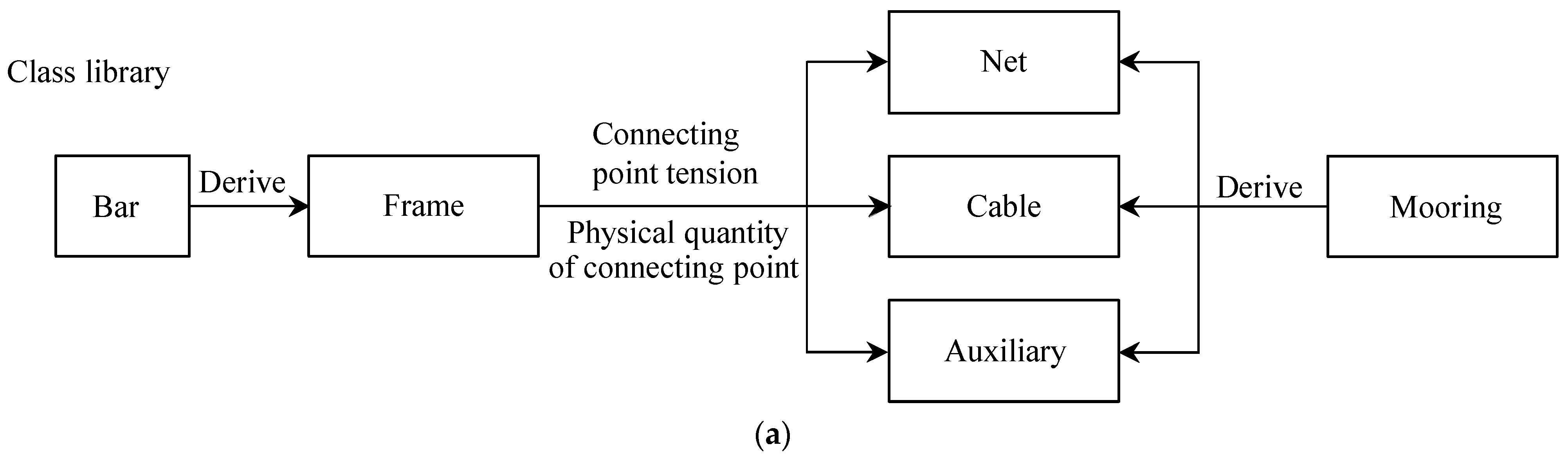
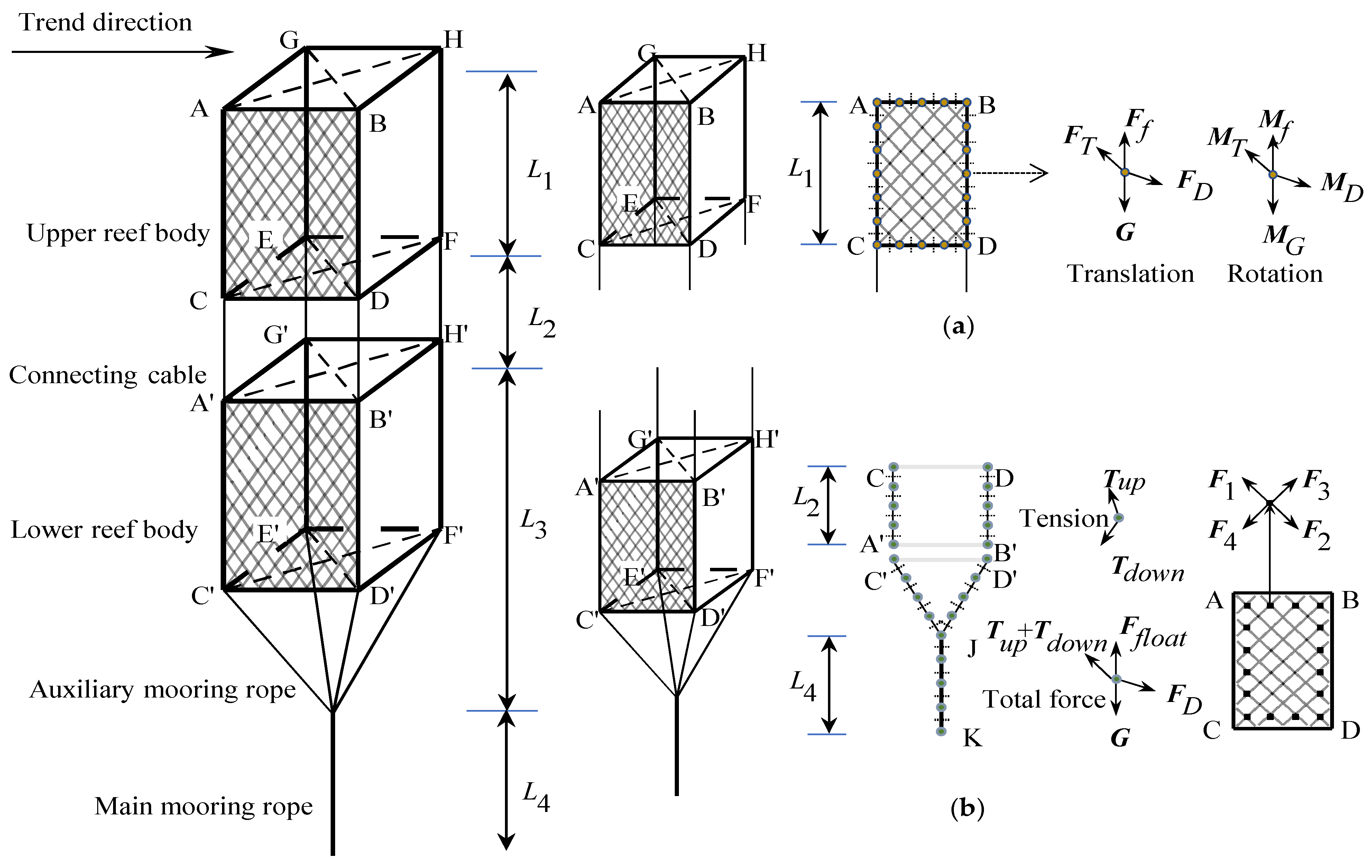
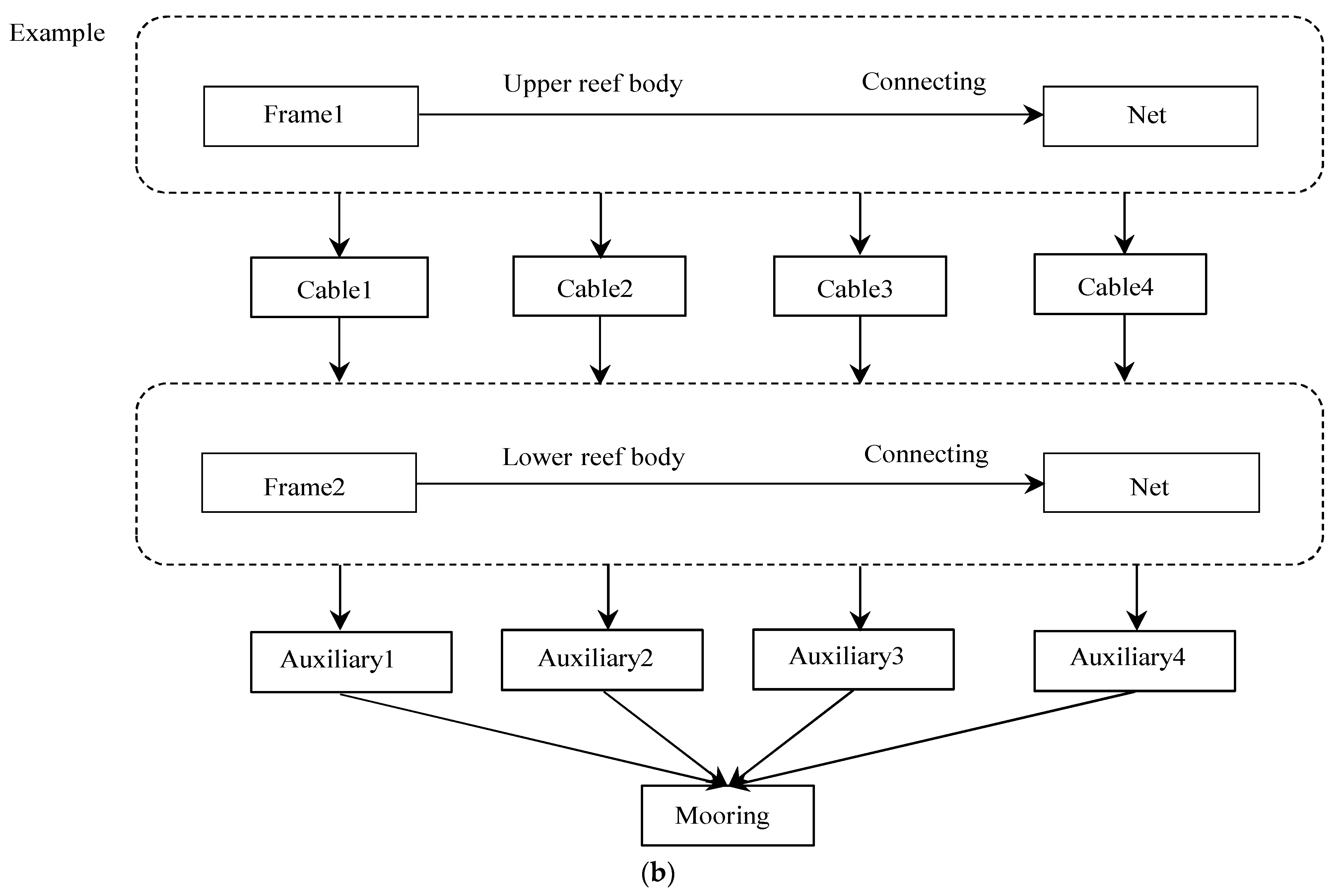
3.3. Model Construction Method

For the detailed numerical model establishment method of single-layer floating reefs, this study refers to [20], which verified the accuracy of the numerical model through physical model tests. So this section only focuses on how to connect layered floating reefs. The finite element method and the lumped mass point method are mainly used to establish the hydrodynamic calculation model of the stratified floating reef, and the tension and motion of each component such as the upper and lower floating frames, netting, cable and mooring rope under the action of tidal current are calculated.
The layered floating reef is a reef tied by a cable above the single-layer reef in Reference [20] and connected to the corresponding four end angles of the upper and lower floating frames with cables, as shown in Figure 1a,b. Therefore, the key point of the establishment of the layered floating reef hydrodynamic numerical model is the connection between the floating frame, the cable and the floating frame; that is, the data exchange between the physical quantities of multiple similar objects. The height of the upper reef is set as L1, and the floating frame is a rigid structure, with its units divided according to the finite element division method. Its movement mainly considers translation and rotation, and it is mainly affected by the netting tension, buoyancy, drag, gravity and so on, which work together as shown in Figure 1a. The lumped mass point method is used to calculate the hydrodynamic forces of the net and mooring rope. The division of the concentrated mass points of cable and mooring rope and their tension diagram are given in Figure 1b. Among them, the concentrated mass point of the mooring rope is subjected to the upper and lower tension and the clockwise tension of the four netting wires at concentrated mass points of the netting named as F1F4, in turn. The lower floating reef is composed of lower reef, auxiliary mooring rope and main mooring rope, and the ratio of the distance from the bottom center of the lower reef floating frame to the auxiliary mooring rope knot to the height of the floating frame is designed to be 0.59 [19]. It can be seen that the force of each component unit and concentrated mass point of the floating reef can be summarized as gravity, buoyancy, tension, tidal drag force, etc., and then the mass point motion equation is established by Newton’s second law. In Reference [20], the force, translation and rotation equations of the four-prism floating frame and the tension, motion and deformation equations of the net, cable and mooring rope are given in detail, which will not be repeated here.
The method of simulating the connection between the cables and the frame is to tie the four connecting cables to the four corners of the upper and lower reefs, respectively. The head point of each cable is the same as the movement of the four corners below the upper reef, and the tail point is the same as the movement of the four corners above the lower reef. In the calculation process, it is only necessary to calculate the motion physical quantity of the four-corner endpoint of the upper and lower reef body, and then assign it to the first and last points of the cable. C++ computer language programming is mainly used to construct the numerical model, force analysis and motion simulation of the layered floating reef. MATLAB (Version 2018a) software is used for visual processing. The upper and lower reefs are only different in size, and the structure and constituent materials are consistent. If the material class library can be established (including physical attribute variables such as material length, diameter, density, spatial position, velocity and acceleration, as well as calculation functions such as force, motion and deformation), a layered floating reef of any shape and combination type can be established efficiently and accurately. The relationship between the base class and the derived class is given in Figure 2a. The four-prism-frame class is evolved from a single-member class, and the rope class can be extended to mooring rope class, cable class, netting class, etc. The material library of the floating reef is established. Then, the instance object can be created according to Figure 2b, where the arrows in the figure represent the connection order between different objects. According to the structural type of the layered floating reef in Figure 1, a total of upper reefs (floating frames and netting), four cables, lower reefs (floating frames and netting), four auxiliary mooring ropes and main mooring ropes were created.

4. The Influence of the Upper and Lower Layer Height on the Force and Motion of the Floating Reef (Connecting Cable L2 = 2 m)

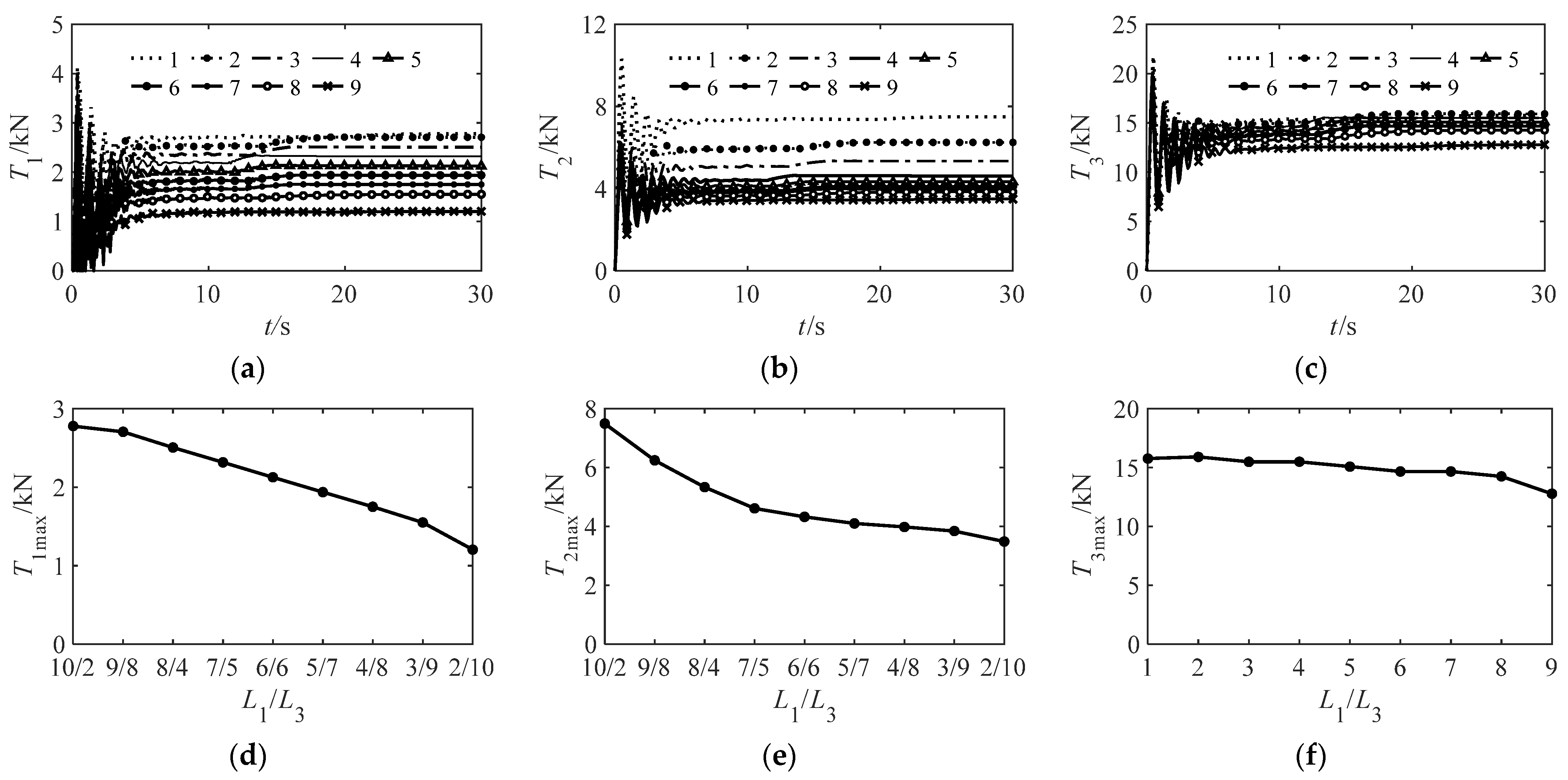
4.1. Tension of Cables, Mooring Ropes and Netting

The influence of the proportion of layered floating reef structure on the tension of connecting cable, auxiliary mooring, main mooring and netting under the action of tidal current is analyzed. The analysis of the influence of different structures of layered floating reefs on the tension of connecting cables, auxiliary mooring ropes, main mooring ropes and netting under tidal current is used to determine whether the designed floating reefs can have better flow resistance and hydrodynamic properties under fixed water depth conditions. The results under the k2 working conditions are shown in Figure 3. T1 (Tension) in Figure 3a represents the tension of the connecting cable. The T1 time history changes under different height conditions of nine kinds (see k2 in Table 2) were drawn and the changing trend of the connecting cable tension under different structure proportions (1–9) was basically the same. After a period of false stability in the middle, it reaches a critical point of force on the cables and then slowly increases to a stable state. T1max in Figure 3d represents the maximum tension of the connecting cable, and the influence of the ratio of L1/L3 on the maximum tension of the connecting cable after stabilization is analyzed at a specific height of L2 (2 m) and L4 (4 m), which decreases with the decrease in L1/L3.
T2 and T2max in Figure 3b,e represent the tension and the maximum tension of the auxiliary mooring rope, respectively. Under the tidal current, the tension of the auxiliary mooring rope of the layered floating reef is greatly affected by L3. The maximum tension gradually tends to be stable when the auxiliary mooring rope is greater than 5 m, which is consistent with the optimal single-mooring conditions for floating reefs mentioned in the literature [19].
T3 and T3max in Figure 3c,f represent the tension and the maximum tension of the main mooring rope, respectively. Under the tidal current, the tension of the main mooring rope of the layered floating reef is relatively large, and the maximum tension of the main mooring rope is significantly greater than that of the connecting cable and the auxiliary mooring rope. The tension of the main mooring rope varies little with the ratio of L1/L3, indicating that the tension of the main mooring rope is not significantly affected by the proportion of the structure.
T4 and T5 in Figure 3g,h represent the resultant force at all the fixing points of the upper netting and the lower netting, respectively. The resultant force can reflect the total hydrodynamic force of the netting. The time history changes of T4 and T5 under different height conditions of nine kinds of upper and lower layers were also drawn. The tension of the upper netting decreases with the increase in the ratio of L1/L3 while the tension of the lower netting increases with the increase in the ratio of L1/L3. L1 and L3 have a greater influence on the upper and lower netting, respectively, and both have a good linear relationship. T4max and T5max in Figure 3i represent the maximum tension of the upper netting and the lower netting, respectively. The maximum tension does not exceed 1.2 kN, and the uniform distribution on the net wire is far less than the limit tension value of the net wire, indicating that the netting structure of the layered floating reef is very safe. The reason why the tension of netting shown in the results fluctuates greatly in the early stage is that the force area of the netting in the direction of the incoming flow is the largest at the beginning, and the netting is subjected to large fluid resistance, resulting in deformation and tension of the netting. As the inclination angle of the floating reef increases, the netting tension gradually increases to a stable state. As the results show, the tension of the netting is much smaller than that of the cables and mooring rope. However, under the action of tidal current, the tension of the upper netting is finally transmitted to the connecting cable through the reef floating frame, and the tension of the lower netting is transmitted to the auxiliary mooring rope.

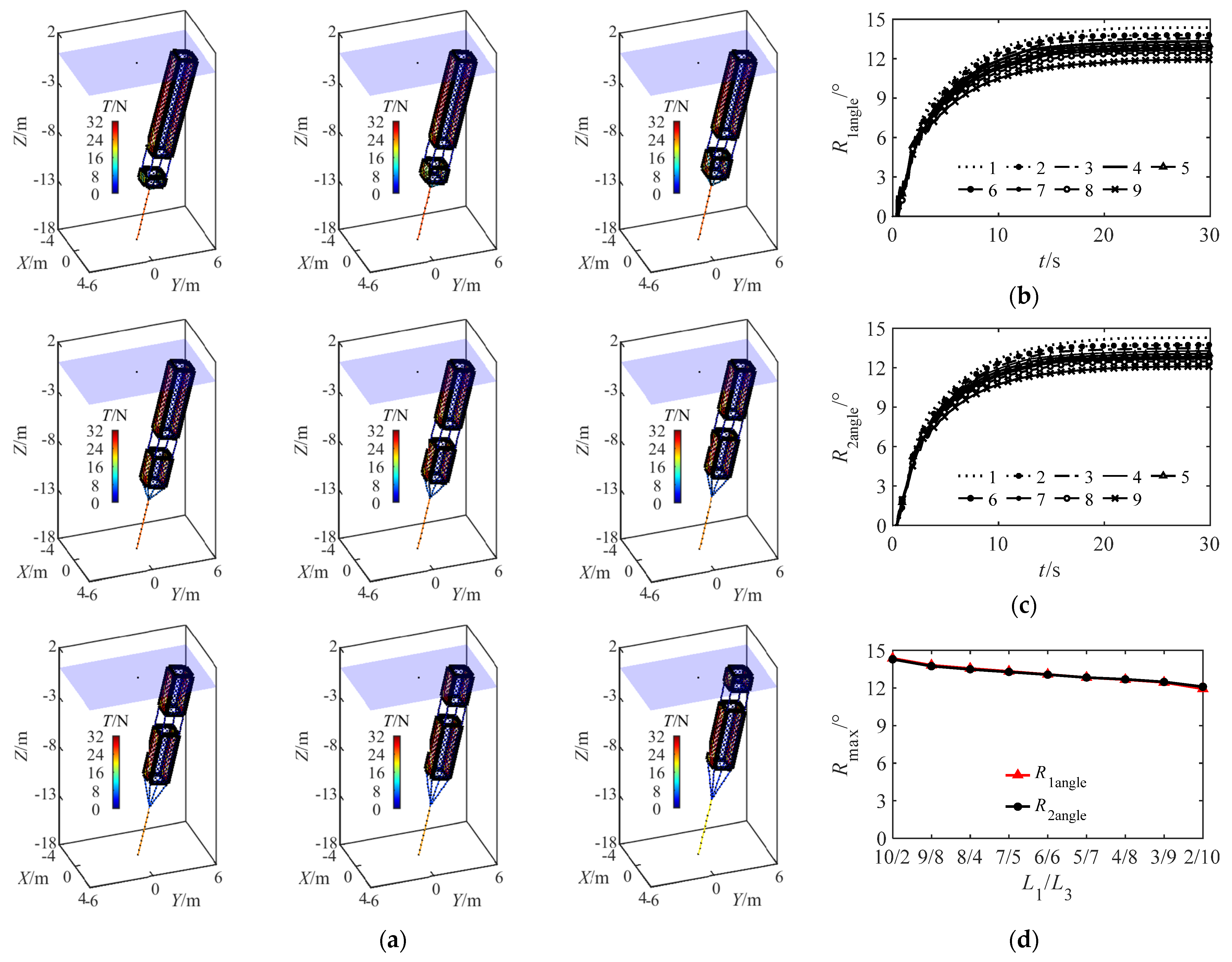
4.2. Influence of Layered Floating Reef Structure on Reef Body Movement

It can be seen from Figure 4d that when the length of the connecting cable (L2 = 2 m) is specified, the rolling angle of the upper and lower reefs of the stratified floating reef decreases slowly due to the decrease in the ratio of the upper and lower heights. It shows that the different structural proportions of the layered floating reef have no obvious effect on the roll of the upper and lower reefs, and the roll part of the layered floating reef is mainly affected by the current. In Figure 4a, the roll angle of the layered floating reef increases with time at a specific flow rate, and the overall shape of the floating reef remains unchanged. Ra1 (Roll-angle), Ra2 and Rmax in Figure 4b–d represent the rolling angle of the upper and lower reefs and the maximum rolling angle of the reef, respectively. The roll angles of the upper and lower reefs initially show a parabolic increasing relationship with time, and the roll angles do not exceed 15° at most and the minimum is about 12° after stabilization. At the same time, the roll angles of the upper and lower reefs are consistent. The above results indicate that the designed layered floating reef can not only make full use of the ocean space to play its own role, but can also maintain a certain stability under the combined effect of tidal current and water depth, which effectively improves the functionality and safety of the floating reef.

5. Optimal Structure of Floating Reef under Tidal Current

The hydrodynamic characteristics of the layered floating reef under the action of tidal current are discussed. The safety of layered floating reef structure is analyzed by calculating the maximum tension of netting, cable and mooring rope, and the stability of layered floating reef structure is ensured by calculating the maximum roll angle of upper reef and lower reef. The layered floating reef is suitable for the construction of marine ranching habitats with upper, middle and lower water depths. It can better use the water space to trap, breed and avoid fish and needs to have good stability and anti-flow characteristics. The force and motion state of the layered floating reef are mainly divided into four groups: k1, k2, k3 and k4. Each working condition is divided into multiple groups of L1/L3 structure proportions, as shown in Table 5, Table 6, Table 7 and Table 8.
The effects of various structural proportional relationships on the force and motion of each component structure of the floating reef were studied under specific water depth and flow velocity. In the simulation, considering that the long cable will affect the utilization of the middle water space, the length of the connecting cable is set to 1 m (k1), 2 m (k2), 3 m (k3) and 4 m (k4). From Table 5, Table 6, Table 7 and Table 8, it can be seen that the maximum tension of the connecting cable is mainly affected by L1, showing a linear decreasing relationship, indicating that the force on the upper reef is finally transmitted to the connecting cable. The maximum tension of the auxiliary mooring rope gradually tends to be relatively stable when L3 is greater than 5 m, which is consistent with the research results of Pan et al. [19]. The maximum tension of the main mooring rope, as the supporting part of the whole layered floating reef, is less affected by different structure of the layered floating reef. The maximum tension of the netting joint is one to two orders of magnitude smaller than that of cables and mooring ropes, so the tension of the upper and lower netting is finally transmitted to the connecting cable, auxiliary mooring ropes and main mooring ropes, respectively. The inclination angles of the upper and lower reefs are basically consistent, and the maximum roll angle of the reef does not exceed 15°, indicating that the designed layered floating reef has good stability and current resistance. The maximum roll angle of the upper and lower reefs has good consistency and does not exceed 15°, which shows that the layered structure of the floating reef has better flow resistance and stability. Based on the above results, it can be concluded that the height of the upper and lower reefs of the stratified floating reef L1/L3 should not be more than one to obtain better water space utilization and stability.

6. Response Verification of Optimal Structure of Floating Reef under Wave-Current Action

Floating reefs are greatly affected by environmental factors such as tides and waves in the actual sea area. Therefore, a combination of theoretical analysis and numerical simulation are used to select the optimal structural ratio of layered floating reefs under the combined action of waves and currents. The optimal proportional lengths are L2 = 4 m, L4 = 4 m, L1 = 2 m and L3 = 8 m, respectively. The effects of wave height and wave steepness on the hydrodynamic characteristics of stratified floating reefs are discussed when the wave and current are in the same direction or opposite direction. In this section, the downstream is defined as the wave-current in the same direction, and the upstream is defined as the wave-current in the opposite direction, as shown in Figure 5, Figure 6, Figure 7 and Figure 8.

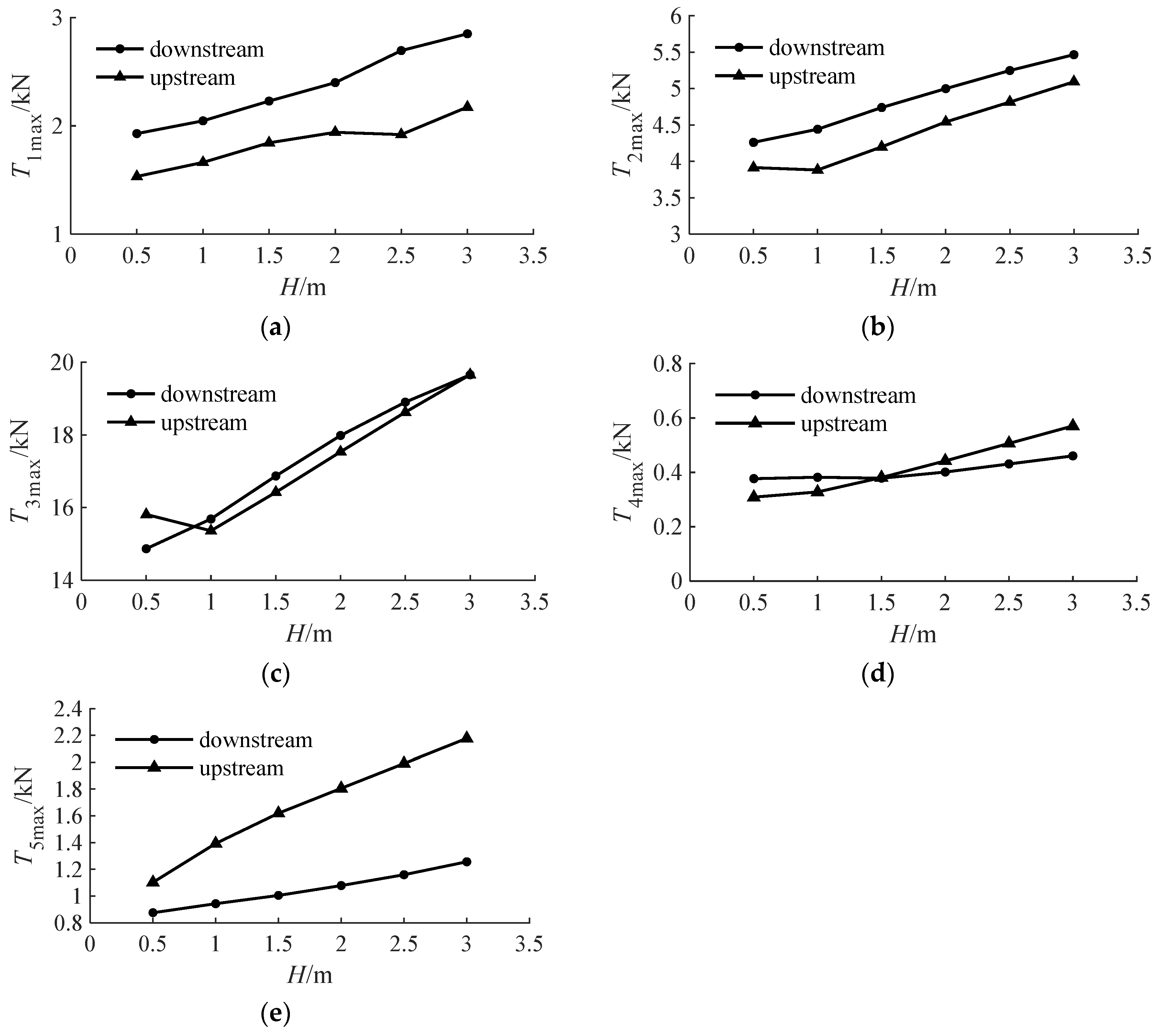
6.1. Influence of Wave Height on the Tension of Cable, Mooring Rope and Netting

T1max, T2max and T3max represent the maximum tension of the connecting cable, the auxiliary mooring rope and the main mooring rope, respectively, as shown in Figure 5a–c. All the above three increase with the increase in wave height when the wave steepness is fixed at 0.05 and the wave and current are in the same direction. The change of wave height has little effect on T1max when the wave height is fixed at 1.5 m and the wave and current are in the opposite direction. Moreover, T2max and T3max reach the minimum when the wave height is 1 m. In addition, the maximum tension of the outer cable and the auxiliary mooring rope when the wave follow the current is greater than the maximum tension when the wave is opposite the current.
T4max and T5max denote the maximum tension of the upper and lower layers of the layered floating reef, respectively. The direction of wave propagation is defined as positive, and the maximum tension of the fixing point of the net is defined as negative, when the wave and current are in the same direction, as shown in Figure 5d,e. The maximum tension of the upper netting fixing point is less affected by the wave height, as shown in Figure 5d. The maximum tension of the lower netting fixing point increases with the increase in wave height. The difference between the two is 0.9 kN when the wave height reaches 3 m. In addition, T5max is always greater than T4max. There are two main reasons for this effect: First, the force of the net is related to the number of net mesh, the length of the net and the size of the net line. The length of the lower net of the selected layered floating reef structure is about three times the length of the upper net. Second, the total upstream area of the lower net line is larger than the total upstream area of the upper net line, resulting in a larger wave force on the lower net.

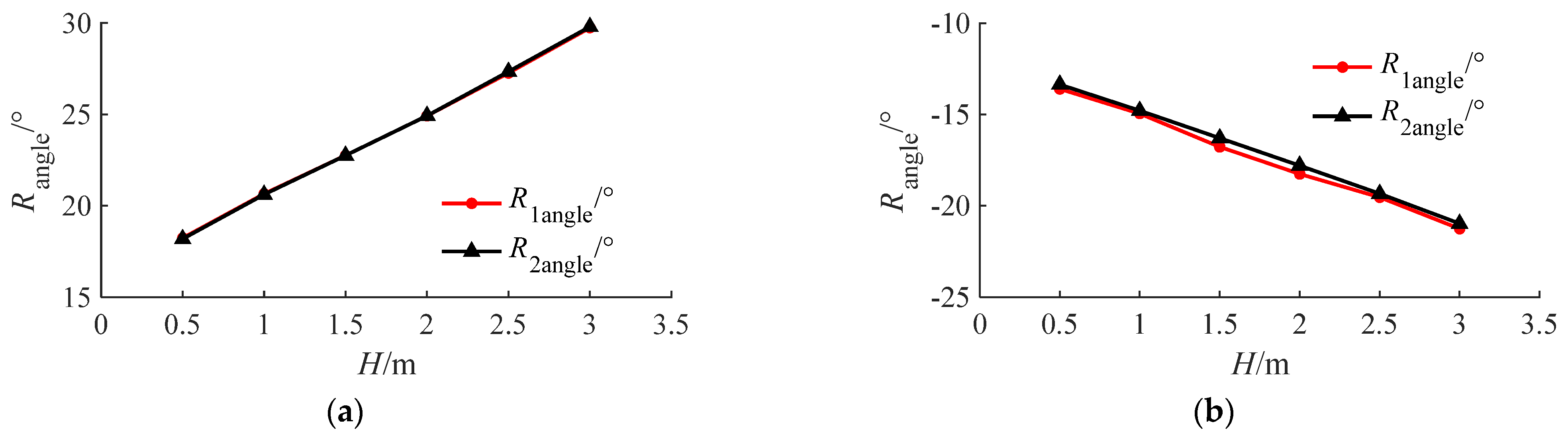
6.2. Influence of Wave Height on Reef Movement

In Figure 6, R1angle and R2angle denote the maximum roll angle of the upper reef and the maximum roll angle of the lower reef, respectively. The above two variables coincide completely and increase linearly with the increase in wave height, which indicates that the stratified floating reef has good consistency and stability under the action of wave and current. The R1angle and R2angle are about 18 degrees when the wave height is 0.5 m. Nevertheless, the R1angle and R2angle are about 30 degrees when the wave height is 3 m. This phenomenon indicates that the roll angle of the reef is greatly affected by the wave height, resulting in a significant tilt change.
In addition, the rolling direction of the reef is opposite to the wave propagation, as shown in Figure 6b, where the negative sign in the figure only indicates the rolling direction of the reef. R1angle and R2angle increase with the increase in wave height under the condition of countercurrent. The R1angle and R2angle are about 13 degrees when the wave height is 0.5 m. The R1angle and R2angle are about 21 degrees when the wave height is 3 m. In general, the maximum roll angle of the reef increases with the increase in wave height under the two conditions of downstream and upstream, which is linearly increasing. The maximum roll angle of the reef under the condition of downstream is greater than that under the condition of upstream.

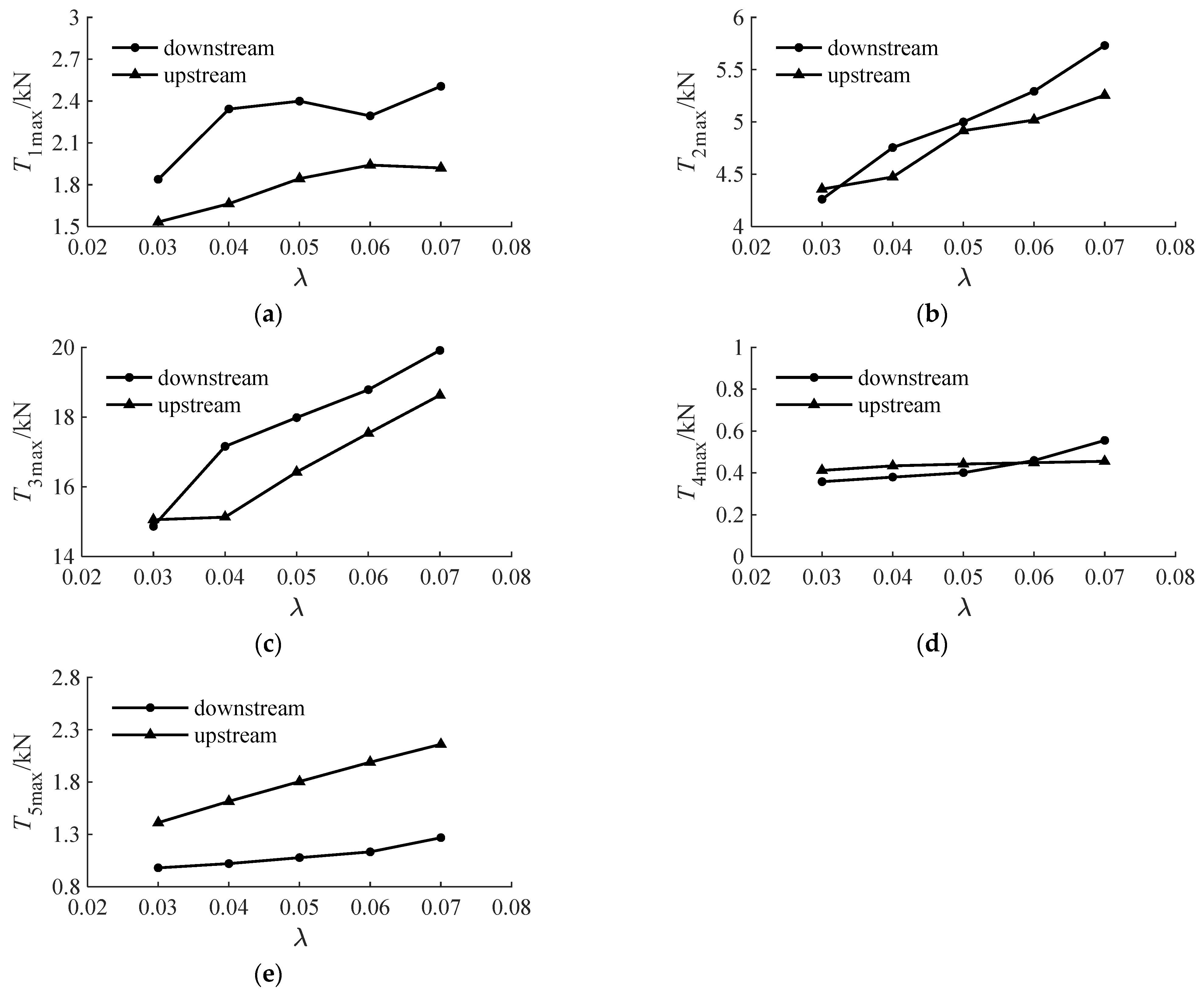
6.3. Influence of Wave Steepness on the Tension of Cable, Mooring Rope and Netting

As an artificial structure providing fish breeding and survival in the sea area, the stability and safety of the floating reef structure are very important in the process of launching and using the floating reef. Some basic elements in the wave, such as wavelength, wave height and wave steepness, have a certain influence on the stability of the floating reef. The above considers the influence of wave height under the action of wave and current. The influence of wave steepness on the force and motion of stratified floating reef is mainly considered. The optimal structural ratios L2 = 4 m, L4 = 4 m, L1 = 2 m and L3 = 8 m of the stratified floating reef under the combined action of wave and current are selected to study the influence of wave steepness change (wave steepness λ = 0.03–0.07, increment is 0.01) on the hydrodynamic characteristics of the stratified floating reef under the combined action of wave and current.
T1max, T2max and T3max represent the maximum tension of the connecting cable, the auxiliary mooring rope and the main mooring rope, respectively, as shown in Figure 7a–c. The maximum tension of the cable and the mooring rope increases with the increase in the wave height when the wave steepness is fixed at 2.0 m. The curve of T2max with wave steepness is basically consistent, as shown in Figure 7a–c. It shows that the auxiliary mooring tension is almost not affected by the direction of wave current. Meanwhile, the maximum tension difference of T3max reaches the maximum when the wave steepness is 0.03, and the maximum tension of the main mooring under the downstream flow is slightly larger than that under the upstream.
In Figure 7d,e, T4max and T5max correspond to the maximum tension of the fixing point of the upper and lower layers of the layered floating reef, respectively. T4max is less affected by wave steepness while T5max increases with the increase in wave steepness. The maximum tension of the total fixing point of the netting in the lower layer is greater than the maximum tension of the downstream flow, which is similar to the influence of the wave height on the tension of the netting.

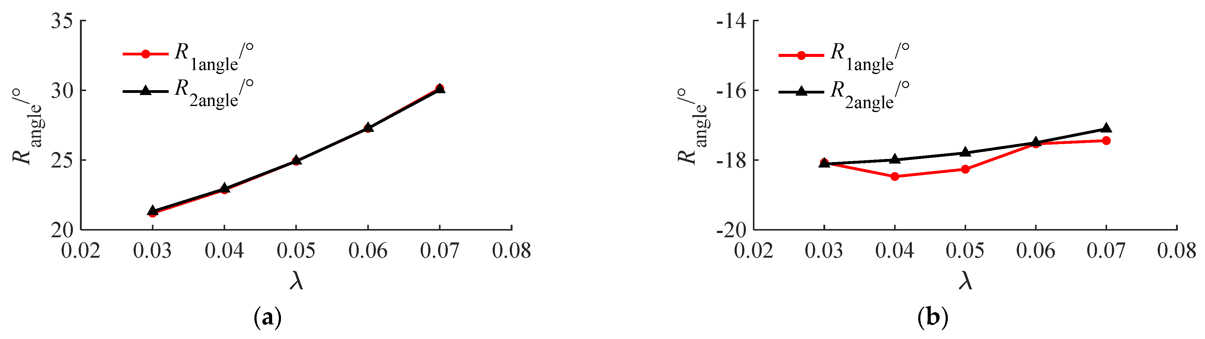
6.4. Influence of Wave Steepness on Reef Movement

The maximum rolling angle of the reef varies with the wave steepness, as shown in Figure 8. R1angle and R2angle are proportional to wave steepness, which is similar to the effect of wave height on the roll angle of stratified floating reefs. The Rangle reaches a minimum of 21 degrees when the wave steepness is 0.03, and the Rangle reaches a maximum of 30 degrees when the wave steepness is 0.07. This difference indicates that the wave steepness has little effect on the roll angle of the floating reef. Furthermore, the maximum negative roll angle difference of the upper and lower reefs is not more than 1 degree under the same wave steepness. It shows that the rolling angle of the stratified floating reef under the condition of countercurrent is less affected by the wave steepness, and the designed stratified floating reef also has good stability.

7. Conclusions

In this paper, a new type of layered floating reef applied to the habitat construction of marine ranching under the condition of large water depth is established. The upper and lower reef structure can improve the utilization space of resource and effectively expand the living space of fish. Based on the field tidal current data, the dynamic conditions of tidal current are set by fitting the vertical distribution formula of tidal current. In this paper, based on the single-layer floating reef model established in reference [19], this paper studies the structural optimization of layered floating reefs and further optimizes and reconstructs the numerical model of floating reefs. The force and motion of the layered floating reef under tidal current are calculated. The effects of different structural heights on the force and motion of the upper and lower reefs, connecting cables, auxiliary mooring ropes and main mooring ropes of the layered floating reef under the action of tidal current are explored. According to the optimal structural ratio obtained under the action of tidal current, the influence of wave height and wave steepness on the force and motion of layered floating reef under the combined action of wave and current is explored. The main conclusions are summarized as follows:
  • Under the specific tidal current, the change of the proportion of the layered floating reef structure has little effect on the roll angle of the reef. The inclination angles of the upper and lower reefs are basically consistent, and the maximum roll angle of the reef does not exceed 15°, indicating that the designed layered floating reef has good stability and current resistance.
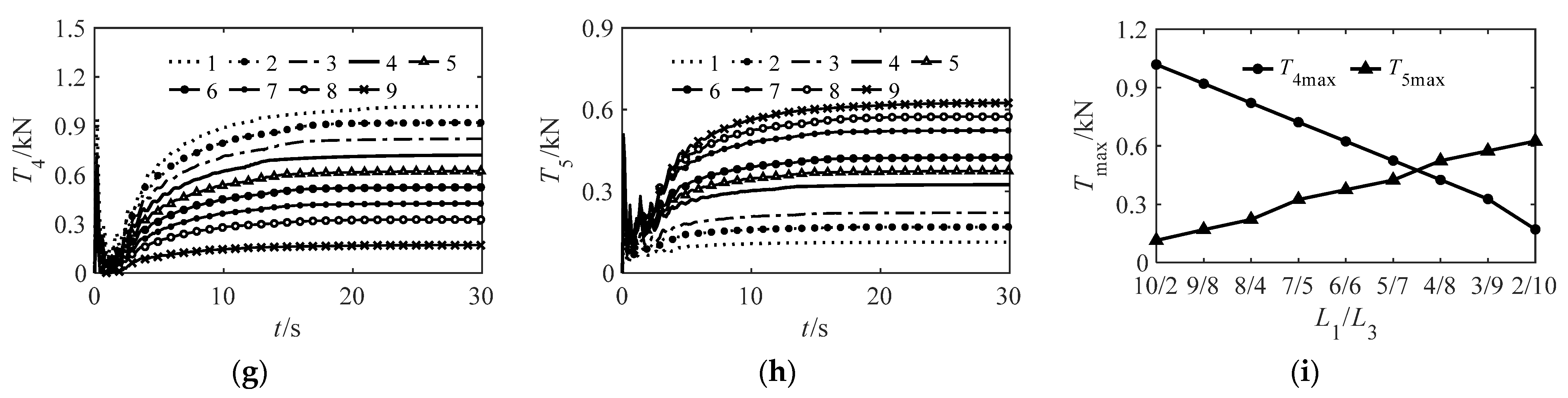
  • Under the action of tidal current, when the stratified floating reef connecting cable is at a specific height of L2 (1 m, 2 m, 3 m, 4 m) and L4 (4 m), the tension of the connecting cable decreases with the decrease in L1/L3 ratio, showing a linear relationship. The maximum tension of the auxiliary mooring rope tends to be stable when L3 is greater than 5 m. The tension of the main mooring rope is not obviously affected by the proportion of layered floating reef structure. The upper net tension and the lower net tension are greatly affected by the length of L1 and L3, respectively, and the net tension is the smallest in the overall floating reef.
  • The structural design of layered floating reefs suggests that the ratio of the sum of the height of the lower reef and the length of the connecting mooring line to the height of the upper reef is not greater than one. It can improve the utilization rate of water space and ensure the stability and safety of layered floating reefs under the influence of tidal current.
  • The tension of layered floating reef structure is greatly affected by wave height and wave steepness. The maximum tension of connecting cable, auxiliary mooring, main mooring and upper and lower net fixing points increases with the increase in wave height and wave steepness when the wave current direction is consistent and opposite. The overall stability of the floating reef mainly depends on the force of the mooring rope. Therefore, the strength coefficient of the mooring rope should be increased when the floating reef is put into the actual sea area.
  • On the one hand, the wave height has a great influence on the rolling of the upper and lower reefs. The maximum rolling angle of the upper and lower reefs increased linearly when the wave height increased. On the other hand, the wave steepness has a great influence on the rolling of the reef when the wave and current are in the same direction. On the contrary, the impact of wave steepness is smaller when the wave and current are in the opposite direction. Generally, the roll angle of the reef is larger under the combined action of wave and current. Thereby, the maximum rolling angle of the floating reef should be fully considered to avoid the mutual influence between the floating reefs.

Author Contributions

Conceptualization, methodology and writing—original draft preparation, Y.P. and L.Y.; writing—review and check, L.L.; project administration and funding acquisition, L.L.; visualization, D.X. All authors have read and agreed to the published version of the manuscript.

Funding

This research was funded by the National Natural Science Foundation of China (China) (No. 52101330), the basic scientific research business expenses of provincial universities in Zhejiang Province (China) (2022J004) and the Fundamental Research for Zhejiang Provincial Universities and Research Institutes (China) (JX6311181723).

Data Availability Statement

Not applicable.

Acknowledgments

We would like to thank Zhao Xizeng of Zhejiang University for the measured data of tidal current in the Zhoushan sea area.

Conflicts of Interest

The authors declare no conflict of interest.

References

  1. Shu, A.; Qin, J.; Rubinato, M.; Sun, T.; Wang, M.; Wang, S.; Zhu, F. An Experimental Investigation of Turbulence Features Induced by Typical Artificial M-Shaped Unit Reefs. Appl. Sci. 2021, 11, 1393. [Google Scholar] [CrossRef]
  2. Pan, Y.; Tong, H.; Wei, D.; Xiao, W.; Xue, D. Review of Structure Types and New Development Prospects of Artificial Reefs in China. Front. Mar. Sci. 2022, 9, 1190. [Google Scholar] [CrossRef]
  3. Gunn, D.; Rudman, M.; Cohen, R. Wave Interaction with a Tethered Buoy: SPH Simulation and Experimental Validation. Ocean Eng. 2018, 156, 306–317. [Google Scholar] [CrossRef]
  4. Altomare, C.; Tafuni, A.; Domínguez, J.M.; Crespo, J.C.; Giron, X.; Sospedr, J. SPH simulations of real sea wavesimpacting a large-scale structure. J. Mar. Sci. Eng. 2020, 8, 826. [Google Scholar] [CrossRef]
  5. Domínguez, J.M.; Crespo, A.J.C.; Hall, M.; Altomare, C.; Wu, M.; Stratigaki, V.; Troch, P.; Cappietti, L.; Gómez-Gesteira, M. SPH simulation of floating structures with moorings. Coast. Eng. 2019, 153, 103560. [Google Scholar] [CrossRef]
  6. Ma, C.; Zhao, Y.; Bi, C. Numerical Study on Hydrodynamic Responses of a Single-Point Moored Vessel-Shaped Floating Aquaculture Platform in Waves. Aquac. Eng. 2022, 96, 102216. [Google Scholar] [CrossRef]
  7. Touzon, I.; Nava, V.; Gao, Z.; Petuya, V. Frequency Domain Modelling of a Coupled System of Floating Structure and Mooring Lines: An Application to a Wave Energy Converter. Ocean Eng. 2021, 220, 108498. [Google Scholar] [CrossRef]
  8. Zhu, X.; Yoo, W.S. Dynamic Analysis of a Floating Spherical Buoy Fastened by Mooring Cables. Ocean Eng. 2016, 121, 462–471. [Google Scholar] [CrossRef]
  9. Park, S.; Lee, J.; Lee, C.-W. Accuracy improvement of numerical simulation with the determination of drag coefficients of floating collars. Aquac. Eng. 2020, 90, 102105. [Google Scholar] [CrossRef]
  10. Mohapatra, S.C.; Bernardo, T.A.; Soares, C.G. Dynamic wave induced loads on a moored flexible cylindrical net cage with analytical and numerical model simulations. Appl. Ocean Res. 2021, 110, 102591. [Google Scholar] [CrossRef]
  11. Selvan, S.A.; Gayathri, R.; Behera, H.; Meylan, M.H. Surface wave scattering by multiple flexible fishing cage system. Phys. Fluids 2021, 33, 037119. [Google Scholar] [CrossRef]
  12. Bai, X.; Yang, C.; Luo, H. Hydrodynamic performance of the floating fish cage under extreme waves. Ocean Eng. 2021, 231, 109082. [Google Scholar] [CrossRef]
  13. Shaik, A.S.; Thuvanismail, N.; Vijayakumar, M.; Kumar, P. Numerical Investigation on Different Configurations of Offshore Fish Cages in Submerged Conditions Subjected to Regular Waves. J. Mar. Sci. Appl. 2023, 22, 445–455. [Google Scholar] [CrossRef]
  14. Yu, Q.; Ma, J.; An, Y.; Ni, T. The reliminary study of design advantages and problems on artificial floating fish reef of floating rope cage. J. Anhui Agric. Sci. 2013, 41, 8194–8195, (In Chinese with English abstract). [Google Scholar]
  15. Zhang, L.; Wang, J.; Hu, Q.; Shen, T. Design and application of offshore middle-upper-layer flexible floating reefs. J. Shanghai Ocean Univ. 2016, 25, 613–619, (In Chinese with English abstract). [Google Scholar]
  16. Han, C.; Liu, K.; Kinoshita, T.; Guo, B.; Zhao, Y.; Ye, Y.; Liu, Y.; Yamashita, O.; Zheng, D.; Wang, W.; et al. Assessing the Attractive Effects of Floating Artificial Reefs and Combination Reefs on Six Local Marine Species. Fishes 2023, 8, 248. [Google Scholar] [CrossRef]
  17. Wan, R.; Zhou, T.; Zhou, C.; Zhao, F.; Wang, W. Experimental and numerical investigations of hydrodynamic response of biodegradable drifting Fish Aggregating Devices (FADs) in waves. Ocean Eng. 2022, 244, 110436. [Google Scholar] [CrossRef]
  18. Liu, C.; Dong, Z.; Pan, Y.; Tong, H.; Yang, J. An Improved Approach for Interaction of Wave with Floating Spheres and Its Applications. China Ocean Eng. 2023, 37, 115–130. [Google Scholar] [CrossRef]
  19. Pan, Y.; Yang, F.; Bi, C.; Li, L.; Zhou, Y. Study of optimal mooring mode of single mooring for middle and upper layer floating fish attractor. J. Dalian Univ. Technol. 2021, 61, 172–179, (In Chinese with English abstract). [Google Scholar]
  20. Pan, Y.; Tong, H.; Zhou, Y.; Liu, C.; Xue, D. Numerical Simulation Study on Environment-Friendly Floating Reef in Offshore Ecological Belt under Wave Action. Water 2021, 13, 2257. [Google Scholar] [CrossRef]
  21. Wang, S.; Feng, D.; Gun, F.; Xu, Z. Dynamic Behavior of the Net of a Pile-Net-Gapped Enclosure Aquaculture Facility. J. Mar. Sci. Eng. 2022, 10, 1166. [Google Scholar] [CrossRef]
  22. Gao, J.; He, Z.; Huang, X.; Liu, Q.; Zang, J.; Wang, G. Effects of free heave motion on wave resonance inside a narrow gap between two boxes under wave actions. Ocean Eng. 2021, 224, 108753. [Google Scholar] [CrossRef]
  23. Gao, J.; Jing, L.; Wang, J.; Zhang, J.; Liu, Q.; Zang, J.; Tao, Z. Study on transient gap resonance with consideration of the motion of floating body. China Ocean Eng. 2022, 36, 994–1006. [Google Scholar] [CrossRef]
  24. Gao, J.; Chen, H.; Zang, J.; Chen, L.; Wang, G.; Zhu, Y. Numerical investigations of gap resonance excited by focused transient wave groups. Ocean Eng. 2020, 212, 107628. [Google Scholar] [CrossRef]
Figure 1. Structural diagram of layered floating reef. (a) Upper floating frame unit division and force diagram. (b) Lower floating reef unit division and force diagram.
Water 15 03892 g001
Figure 2. Program class library and example creation diagram of layered floating reef. (a) Layered floating reef class library diagram. (b) Layered floating reef example diagram.
Water 15 03892 g002aWater 15 03892 g002b
Figure 3. The effect of the proportion structure of layered floating reef on the tension of cable, mooring and netting. (a) Time-varying of the connecting cable tension; (b) time-varying of the auxiliary mooring tension; (c) time-varying of the main mooring tension; (d) effect of structural proportion on the maximum tension of connecting cable; (e) effect of structural proportion on the maximum tension of auxiliary mooring; (f) effect of structural proportion on the maximum tension of main mooring; (g) time-varying of total tension of the upper netting fixing points; (h) time-varying tension of lower netting fixing points; (i) effect of structural proportion on the maximum tension of upper and lower nettings.
Water 15 03892 g003aWater 15 03892 g003b
Figure 4. The effect of structural proportion of layered floating reef on reef movement. (a) Kinestate of the layered floating reef and force distribution of netting at the moment of maximum rolling angle; (b) time-varying of the upper reef rolling angle; (c) time-varying of the lower reef rolling angle; (d) effect of structural proportion on the maximum rolling angle of upper and lower reefs.
Water 15 03892 g004
Figure 5. The maximum tension of cable, mooring rope and netting fixing point varies with wave height. (a) The maximum tension of the connecting cable varies with the wave height; (b) the maximum tension of the auxiliary mooring varies with the wave height; (c) the maximum tension of the main mooring varies with the wave height; (d) the maximum tension of the upper netting fixing points varies with the wave height; (e) the maximum tension of the lower netting fixing points varies with the wave height.
Water 15 03892 g005
Figure 6. The maximum rolling angle of the reef varies with the wave height. (a) The maximum rolling angle of the upper and lower reefs varies with the wave height (downstream); (b) the maximum rolling angle of the upper and lower reefs varies with the wave height (upstream).
Water 15 03892 g006
Figure 7. The maximum tension of cable, mooring rope and netting fixing point varies with wave steepness. (a) The maximum tension of the connecting cable varies with the wave steepness; (b) the maximum tension of the auxiliary mooring varies with the wave steepness; (c) the maximum tension of the main mooring varies with the wave steepness; (d) the maximum tension of the upper netting fixing points varies with the wave steepness; (e) the maximum tension of the lower netting fixing points varies with the wave steepness.
Water 15 03892 g007
Figure 8. The maximum rolling angle of the reef varies with the wave steepness. (a) The maximum rolling angle of the upper and lower reefs varies with the wave steepness (downstream); (b) the maximum rolling angle of the upper and lower reefs varies with the wave steepness (upstream).
Water 15 03892 g008
Table 1. Parameters of layered floating reef.
StructureMaterialsSize (m)Diameter (m)Density (kg/m3)Coefficient of Drag Force
CD
Coefficient of
Elasticity
C1
Coefficient of
Elasticity
C2
Upper floating frameHDPE1.69 × 1.69 × L10.2646.570.8//
Upper nettingPE6.76 × L10.0039530.6345.3 × 1061.0121
Connecting cablePEL20.029530.6345.3 × 1061.0121
Lower floating frameHDPE1.69 × 1.69 × L3/1.590.2646.570.8//
Lower nettingPE6.76 × L3/1.590.0039530.6345.3 × 1061.0121
Auxiliary mooring ropePEL3/1.59 × 0.590.029530.6345.3 × 1061.0121
Main mooring ropePE4.0 (L4)0.049530.6345.3 × 1061.0121
Notes: HDPE is high-density polyethylene; PE is polyethylene; CD is drag coefficient; C1 and C2 are elastic coefficients.
Table 2. The grouping working conditions table of stratified floating reef structure proportion.
Working ConditionsL2/mL1/L3L4/m
12345678910
k1111/210/39/48/57/66/75/84/93/102/114
k2210/29/38/47/56/65/74/83/92/10 4
k339/28/37/46/55/64/73/82/9 4
k448/27/36/45/54/63/72/8 4
Table 3. Maximum flow rate (m/s) and flow direction (°) during field tide period.
StationTidal CurrentSurface Layer0.2 d0.4 d0.6 d0.8 dBottom LayerVertical Average
RateDirection
1#Rising tidal current1.193261.223121.303171.303311.213201.053021.23322
Falling tidal current1.101531.161321.101581.171491.181450.991291.13140
2#Rising tidal current1.233161.243331.243091.203231.163201.073091.20320
Falling tidal current1.151291.141281.161391.151301.131291.041481.14133
3#Rising tidal current1.223121.223181.163291.153301.113161.013291.15323
Falling tidal current1.141401.141571.151571.171321.141291.051571.14145
4#Rising tidal current1.213231.293281.283311.263211.233091.133281.25323
Falling tidal current1.141561.201331.201351.221331.201291.111321.19135
5#Rising tidal current1.283111.283321.273111.231341.203241.113111.24318
Falling tidal current1.161341.141461.161351.121401.081521.001281.12141
Table 4. The least square fitting coefficient of possible maximum flow velocity distribution function.
ConditionsThe Possible Maximum Flow Velocity
1#2#3#4#5#
a ( × 10−7)42,36932,74940,00628,09032,732
b ( × 10−4)10,16010,13010,18910,01910,157
R2 ( × 10−4)72,48483,42675,44273,54278,808
Table 5. The working condition k1 (L2 = 1 m, L4 = 4 m) includes layered floating reef stress condition and movement state.
Layered Floating Reef Tension
and Movement
L1/L3
11/2
1
10/3
2
9/4
3
8/5
4
7/6
5
6/7
6
5/8
7
4/9
8
3/10
9
2/11
2
Maximum tension of connecting cable3.02.92.72.52.32.11.91.71.51.2
Maximum tension of auxiliary mooring7.96.55.64.84.54.34.24.03.93.7
Maximum tension of main mooring16.816.716.316.315.915.515.515.014.613.8
Maximum tension of upper netting1.11.00.90.80.70.60.50.40.30.2
Maximum tension of lower netting0.10.20.20.30.40.40.50.60.60.7
Maximum rolling of upper reef14.413.913.713.513.313.112.912.712.512.2
Maximum rolling of lower reef14.413.913.713.513.313.112.912.712.512.2
Table 6. The working condition k2 (L2 = 2 m, L4 = 4 m) includes layered floating reef stress condition and movement state.
Layered Floating Reef Tension
and Movement
L1/L3
10/2
1
9/3
2
8/4
3
7/5
4
6/6
5
5/7
6
4/8
7
3/9
8
2/10
9
Maximum tension of connecting cable2.82.72.52.32.11.91.81.61.2
Maximum tension of auxiliary mooring7.56.25.34.64.34.14.03.83.5
Maximum tension of main mooring15.815.915.515.515.114.714.714.312.8
Maximum tension of upper netting1.00.90.80.70.60.50.40.30.2
Maximum tension of lower netting0.10.20.20.30.40.40.50.60.6
Maximum rolling of upper reef14.413.813.613.313.112.812.712.411.9
Maximum rolling of lower reef14.313.713.513.31312.812.712.512.1
Table 7. The working condition k3 (L2 = 3 m, L4 = 4 m) includes layered floating reef stress condition and movement state.
Layered Floating Reef Tension
and Movement
L1/L3
9/2
1
8/3
2
7/4
3
6/5
4
5/6
5
4/7
6
3/8
7
2/9
8
Maximum tension of connecting cable2.52.52.32.11.91.71.51.2
Maximum tension of auxiliary mooring7.15.95.04.44.13.93.73.4
Maximum tension of main mooring14.715.014.714.714.213.813.812.4
Maximum tension of upper netting0.90.80.70.60.50.40.30.2
Maximum tension of lower netting0.10.20.20.30.40.40.50.6
Maximum rolling of upper reef14.213.713.313.112.912.612.411.8
Maximum rolling of lower reef14.213.613.313.012.912.612.412.0
Table 8. The working condition k4 (L2 = 4 m, L4 = 4 m) includes layered floating reef stress and movement state.
Layered Floating Reef Tension
and Movement
L1/L3
8/2
1
7/3
2
6/4
3
5/5
4
4/6
5
3/7
6
2/8
7
Maximum tension of connecting cable2.32.32.11.91.71.51.2
Maximum tension of auxiliary mooring6.75.54.84.13.93.73.6
Maximum tension of main mooring13.814.013.713.813.412.812.1
Maximum tension of upper netting0.80.70.60.50.40.30.2
Maximum tension of lower netting0.10.20.20.30.40.40.5
Maximum rolling of upper reef1413.413.112.812.512.211.7
Maximum rolling of lower reef13.913.413.012.812.512.311.9
Disclaimer/Publisher’s Note: The statements, opinions and data contained in all publications are solely those of the individual author(s) and contributor(s) and not of MDPI and/or the editor(s). MDPI and/or the editor(s) disclaim responsibility for any injury to people or property resulting from any ideas, methods, instructions or products referred to in the content.

