Abstract
The water distribution castellum at the terminal end of the Pont du Gard aqueduct serving the Roman city of Nemausus in southern France is analyzed for its water engineering design and operation. By the use of modern hydraulic engineering analysis methods applied to analyze the castellum, new aspects of Roman water engineering technology are discovered not previously reported in the archaeological literature. Analysis of the castellum’s 10 basin wall flow distribution pipelines reveals that when a Roman version of modern critical flow theory is utilized in their design, the 10 pipelines optimally transfer water to city precincts at the maximum flow rate possible with a total flow rate closely approximating the input flow rate from the aqueduct. The castellum’s three drainage floor ports serve as additional fine-tuning to precisely match the input aqueduct flow rate to the optimized 10 pipeline output flow rate. The castellum’s many hydraulic engineering features provide a combination of advanced water engineering technology to optimize the performance of the water distribution system while at the same time enhancing the castellum’s aesthetic water display features typical of Roman values. While extensive descriptive archaeological literature exists on Roman achievements related to their water systems both in Rome and its provinces, what is missing is the preliminary engineering knowledge base that underlies many of their water system’s designs. The present paper is designed to provide this missing link by utilizing modern hydraulic engineering methodologies to uncover the basis of Roman civil engineering practice—albeit in Roman formats yet to be discovered.
Keywords:
Roman; Pont du Gard; water engineering; castellum; aqueduct; CFD analysis; hydraulic design; critical flow 1. Introduction
The Pont du Gard aqueduct, built during the reign of Claudius (40–60 AD), involves many unique hydraulic engineering components and strategies [1,2,3,4] (pp. 181–188 [1]) that collectively worked to deliver water to the Roman city of Nemausus [2,3,5]—now the city of Nîmes in southern France. Water from the Fontaine d’Eure spring at Uzès was conducted to a regulation basin at Lafoux with an overcapacity diversion channel to the Alzon River (Figure 1); the aqueduct was designed to deliver 40,000 m3/day through the ~50 km long aqueduct channel [2]. The Pont du Gard aqueduct/bridge spanning the Gardon River (Figure 2A–C) is located ~25 km from the spring source; a further 25 km extension of the aqueduct channel constructed partway through a tunnel delivered water to the basin distribution center (castellum) located ~17 m above the city of Nemausus. Changes to the original Roman aqueduct were made over the centuries: Figure 2B shows a 1743–1747 pedestrian walkway addition to the original Roman structure devised by French engineer Henri Pitot; further restoration was done in 1850–1855 by Napoleon III to reinforce the original structure. Figure 3 shows structural details of the original aqueduct base; the triangular base structure incorporates Roman knowledge to reduce the flowing water pressure on the foundation base. As the included angle of the aqueduct base exceeds the separation angle, turbulent, large-scale water rotational vortices keep sediment particles in suspension during passage under the bridge thus preventing sediment deposits under the bridge. Water delivered through the castellum basin tunnel opening (Figure 3, Figure 4 and Figure 5) was further conducted through multiple pipelines to city reservoirs and site locations. The ~5.5 m diameter, ~1.0 m high castellum basin wall supported 10 centenum-vicenum ~30 cm terracotta inner diameter pipelines (Figure 6) with three additional pipelines of similar diameter (Figure 6) originating from the basin floor to complete the 13 pipeline distribution system. A sluice plate located at the tunnel opening to the basin regulated basin water height—this feature would prove vital to the design and function of the castellum as later discussion reveals.
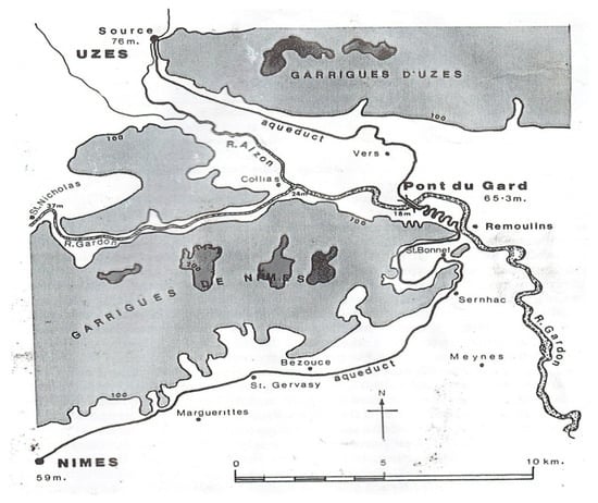
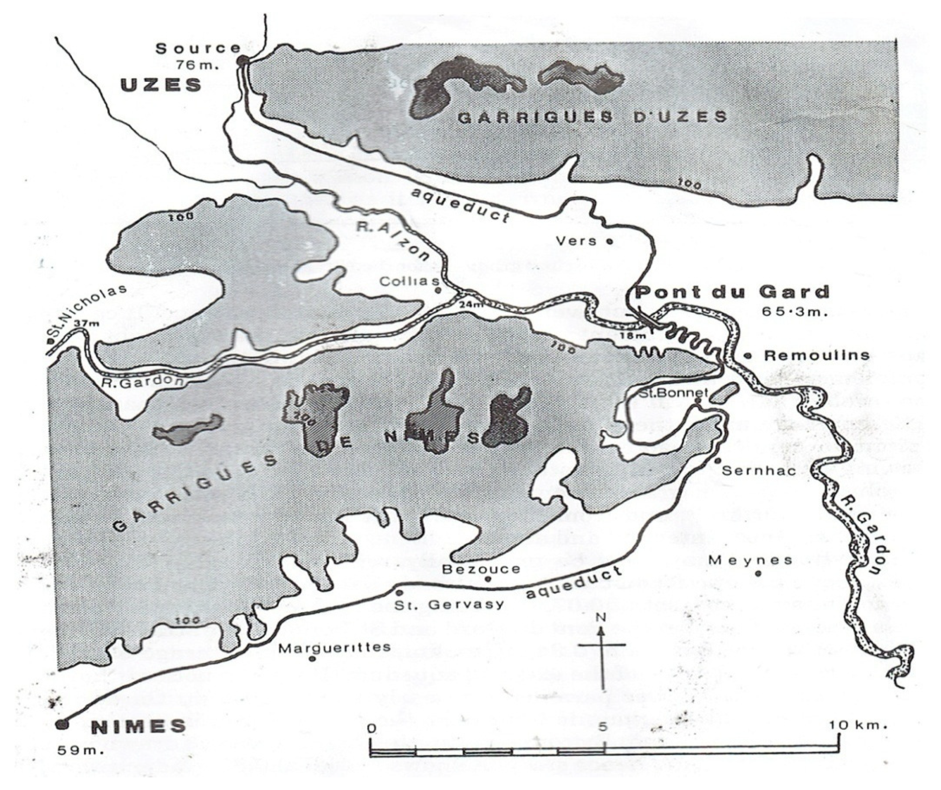
Figure 1.
Map of the Pont du Gard aqueduct water system path from the Fontaine d’Eure source spring at Uzes to the destination castellum.

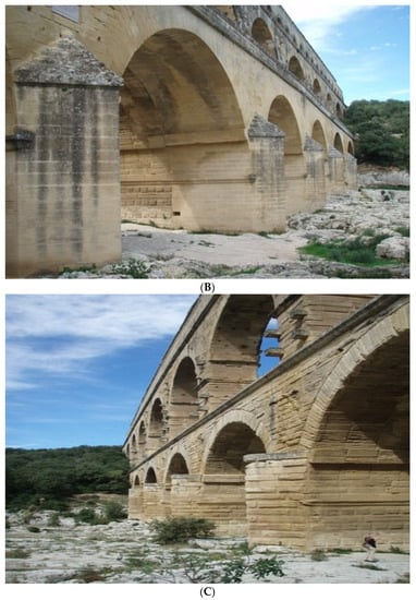
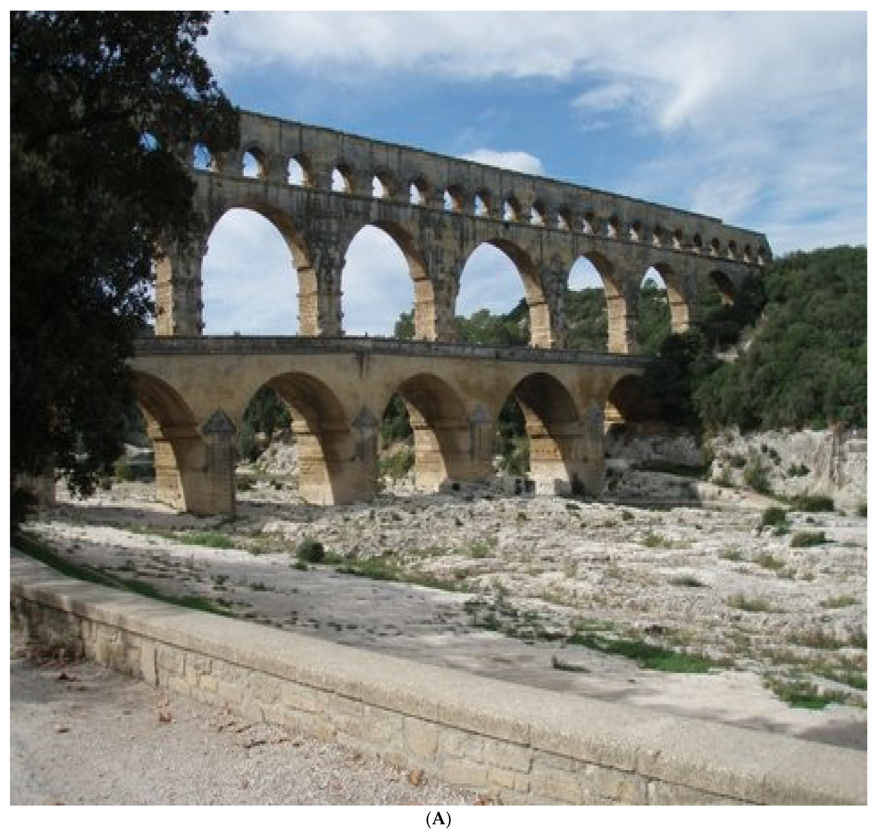
Figure 2.
(A) The Pont du Gard aqueduct/bridge. (B) Later (1743–1747) roadway passage addition to the original Roman Aqueduct. (C) Base structure of the Aqueduct. Note foundation triangular structures to reinforce the aqueduct base and lower river water hydrodynamic pressure forces on the base structure.
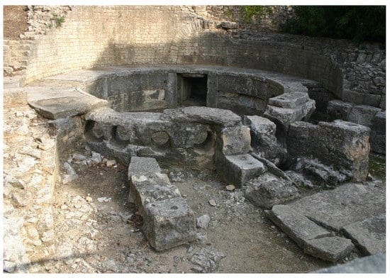
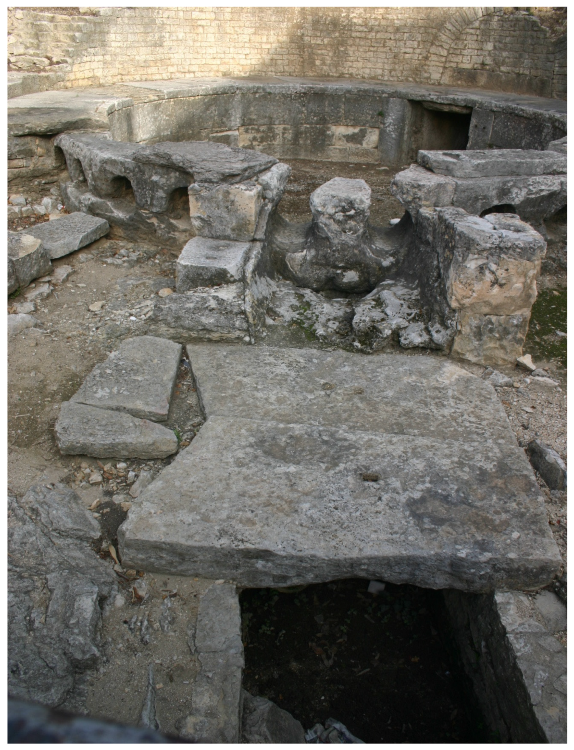
Figure 3.
Front view of the Nîmes castellum.
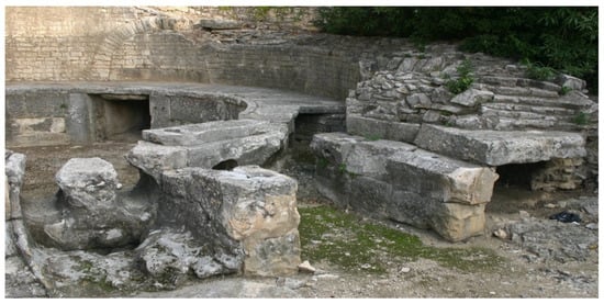
Figure 4.
View of the front of the Nîmes castellum.

Figure 5.
View of structures in front of the Nîmes castellum.
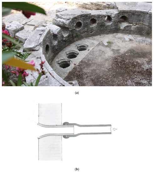
Figure 6.
(a) Interior view of the Nîmes castellum showing three floor drainage ports. Port covers can be moved to adjust flow drainage flow rate output to match aqueduct input flow rate. (b) Typical calyx insert adjoining a pipeline marked with a flow rate value (in quinaria) for attachment to a pipeline to limit its flow rate to a prescribed value.
The Pont du Gard aqueduct/bridge crossed the Gardon River near the town of Vers-Pont du Gard and was a vital element of the ~50 km long aqueduct providing water to Nemausus. The straight-line distance between the Fontaine d’Eure spring source and the terminal distribution castellum was ~25 km; the final channel path selected by Roman engineers was a winding route measuring ~50 km because of construction difficulties associated with the mountainous Garrigues de Nîmes direct route. Roman surveyors selected the longer channel path to avoid difficulties associated with building numerous tunnels and bridges through mountainous terrain that would accompany the shorter length path that led directly from the spring source to the castellum. In addition to construction difficulties associated with the mountainous and deep gorge terrain in the northern section of the proposed aqueduct channel path, further routing changes were necessary to circumvent the southernmost foothills of the Massif Central known as the Garrigues de Nîmes. These foothills, covered in dense vegetation and indented by deep valleys, would prove difficult to cross with the shortest length water channel as they required construction of many small bridges and tunnels through a long section of hills and ravines that required a tunnel between 8 and 10 km long depending on the starting point. A diversion course around the eastern end of the Garrigues de Nîmes mountain range (Figure 1) proved to be the only practical way of transporting water from the origin spring to the city to reduce construction time and minimize labor costs. Ahead of the aqueduct/bridge, a covered continuation channel and terminal tunnel led water to the castellum basin through the sluice gate port shown in Figure 3, Figure 4, Figure 5 and Figure 6. The aqueduct was designed and built to carry a given maximum flow rate of 40,000 m3/day—the challenge to Roman engineers was to efficiently design the castellum to transport the input flow rate through a minimum number of pipelines to city destinations in the most hydraulically efficient manner. The innovative castellum design devised by Roman engineers to accomplish this end is described in sections to follow and gives a penetrating look into Roman hydraulic engineering practice.
In the first century AD, Nemausus was a prosperous Roman colony whose resource base consisted of Rhone Valley agricultural fields and vineyards to support trade and export to central Rome. The colony’s prosperity reflected population growth from 20,000 to 40,000 over a short time span leading to designation of official city status by the central Roman administration. The original Nemausus fountain the base of Mount Cavalier did not provide the expanded city population city with its daily need of potable drinking water nor provide additional water for the baths, fountains, temples, theaters, government and commercial sector buildings and garden areas that Roman cities incorporated as standard city design practice. Based upon the need for increased water supply for the expanding population of the city, planning of an advanced design aqueduct from the Eure Uzés spring source to Nemausus anticipated the future water needs of the city. It is estimated that approximately 70% of the aqueduct channel pathway consisted of excavated stone-lined trenches with slab or arched roof covering with the remainder channel pathway in the form of short length tunnels and small bridges. As a major construction challenge, the Gardon River valley crossing required engineering design and construction innovations on a scale exceeding previous aqueduct designs to transport water across the extensive width of the river gorge area.
The planning and construction of the aqueduct during the ~19 BC time period is credited to Augustus‘ son-in-law and aide, Marcus Vipsanius Agrippa then serving as the senior magistrate aedile responsible for managing the water supply of Rome and its colonies. Espérandieu [3] writing in 1926 linked the construction of the aqueduct with Agrippa’s visit to Narbonensis; later excavations [2,5,6] suggest the construction may have taken place between 40 and 60 AD. Earlier built tunnels bringing water from several local springs to the city were not considered in modification plans originated by the builders of the new aqueduct due to the greatly increased water needs required by the growing city population. Coins discovered in Nemausus’ outflow pipeline catchments are no older than the reign of the emperor Claudius (41–54 AD) to more securely date construction time. On this basis, a team led by Guilhem Fabre [3] argued that the aqueduct must have been completed in the middle of the first century AD and have taken approximately fifteen years to build, employing between 800 and 1000 workers.
2. The Pont du Gard Aqueduct/Bridge Design
The Pont du Gard aqueduct/bridge has three tiers of arches, stands 48.8 m high and descends only 2.5 cm over its length of 274 m (a gradient of 1 in 18,241). The water channel from the Fontaine d’Eure spring source to the castellum descends by only 17 m height over its entire ~50 km length—this is indicative of the challenge in surveying precision that Roman water engineers utilized in the aqueduct design. Average slopes in meters per kilometer (and degrees per kilometer) over long sections of the channel from the Fontaine d’Eure spring at Uzès (Figure 7) to the castellum indicate mean constant slopes over long stretches of the aqueduct channel; local slope variations along channel path lengths were necessary due to local landscape surface irregularities and accuracy limits of surveyor’s instruments [1]. The water supply system may have been in use as late as the sixth century, with some parts used for significantly longer times, but lack of maintenance after the fourth century led to accumulation of channel sinter deposits that eventually limited the water flow rate [2]. Construction details (Figure 3, Figure 4 and Figure 5) of the castellum indicate 10 castellum basin wall ports from which 10 terracotta pipelines directed water to individual fountains, nymphea, baths, temples, gardens, theaters, commercial sector and administrative buildings, private homes and intermediate reservoirs around the city. Three pipeline ports (Figure 6) on the floor of the castellum basin served for adjustable basin drainage, flow diversion during repairs and cleaning of the castellum and, when partially opened by movable cover plates, served as an adjustment mechanism to guarantee that the ~40,000 m3/day aqueduct delivery rate closely matched the design output flow rate from the 10 basin wall pipelines.
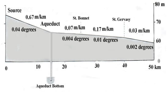
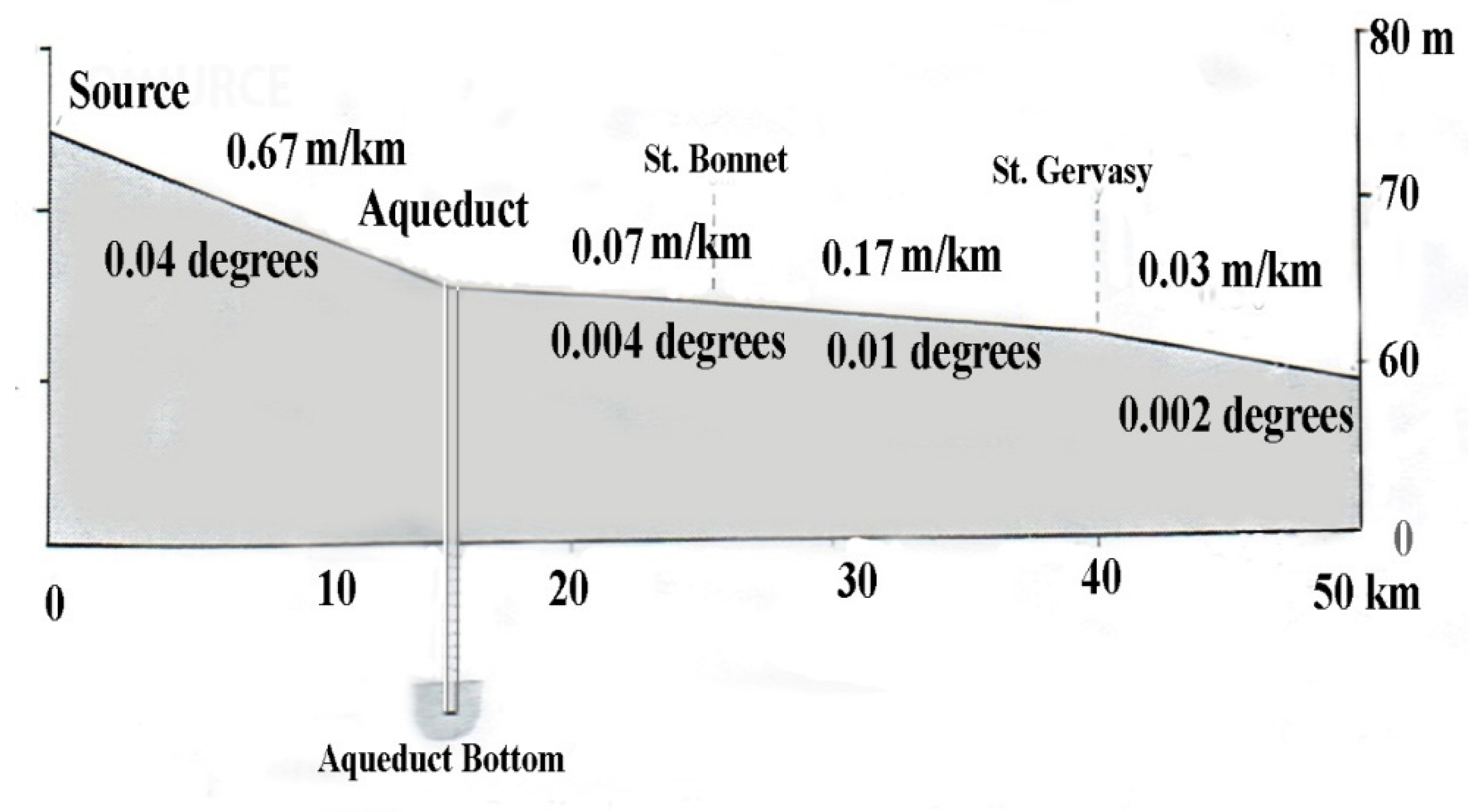
Figure 7.
Average slopes of sections of the Pont du Gard aqueduct in m/km and equivalently in degrees.
The Fontaine d’Eure spring, at 76 m above sea level, is 17 m higher than the castellum above the city of Nemausus; this provided sufficient gradient to sustain gravity flow of aqueduct water to Neamausus. The aqueduct’s average gradient is ~1/3000 but the local channel slope varies widely along its course [2,3] being as small as ~1/20,000 in some sections (Figure 7). The average gradient between the start and end of the aqueduct (0.34 m/km) is far shallower than usual for Roman aqueducts being only approximately one-tenth of the average gradient of some of the eleven aqueducts supplying Rome. The reason for the change in gradients along the water system’s route is that a uniform gradient would have meant that the Pont du Gard aqueduct/bridge would have an extreme height and thus present a formidable construction challenge given the limitations of Roman construction technology. By maintaining a steeper gradient along the channel path ahead of the aqueduct/bridge (Figure 7), Roman engineers were able to lower the height of the aqueduct/bridge by 6 m to a total height of 48.7 m above the Gardon River bed. This height limit governed both the up- and downstream channel gradients of the aqueduct as well as limiting the weight of the aqueduct. Despite the weight saving design, the substantial as-constructed weight of the multi-tiered stonework created a slight depression in the middle of the aqueduct/bridge that created a slightly increased water depth in the center of the aqueduct channel. The initial gradient profile originating from the spring source before the aqueduct/bridge is relatively steep descending 0.67 m/km but descends by only 6 m over the remaining channel length to the castellum (Figure 7). In one channel section, the winding route between the Pont du Gard aqueduct/bridge and St. Bonnet (Figure 1) required an extraordinary degree of accuracy from Roman engineers who had to survey for a channel decline of only 7 mm per 100 m of the aqueduct.
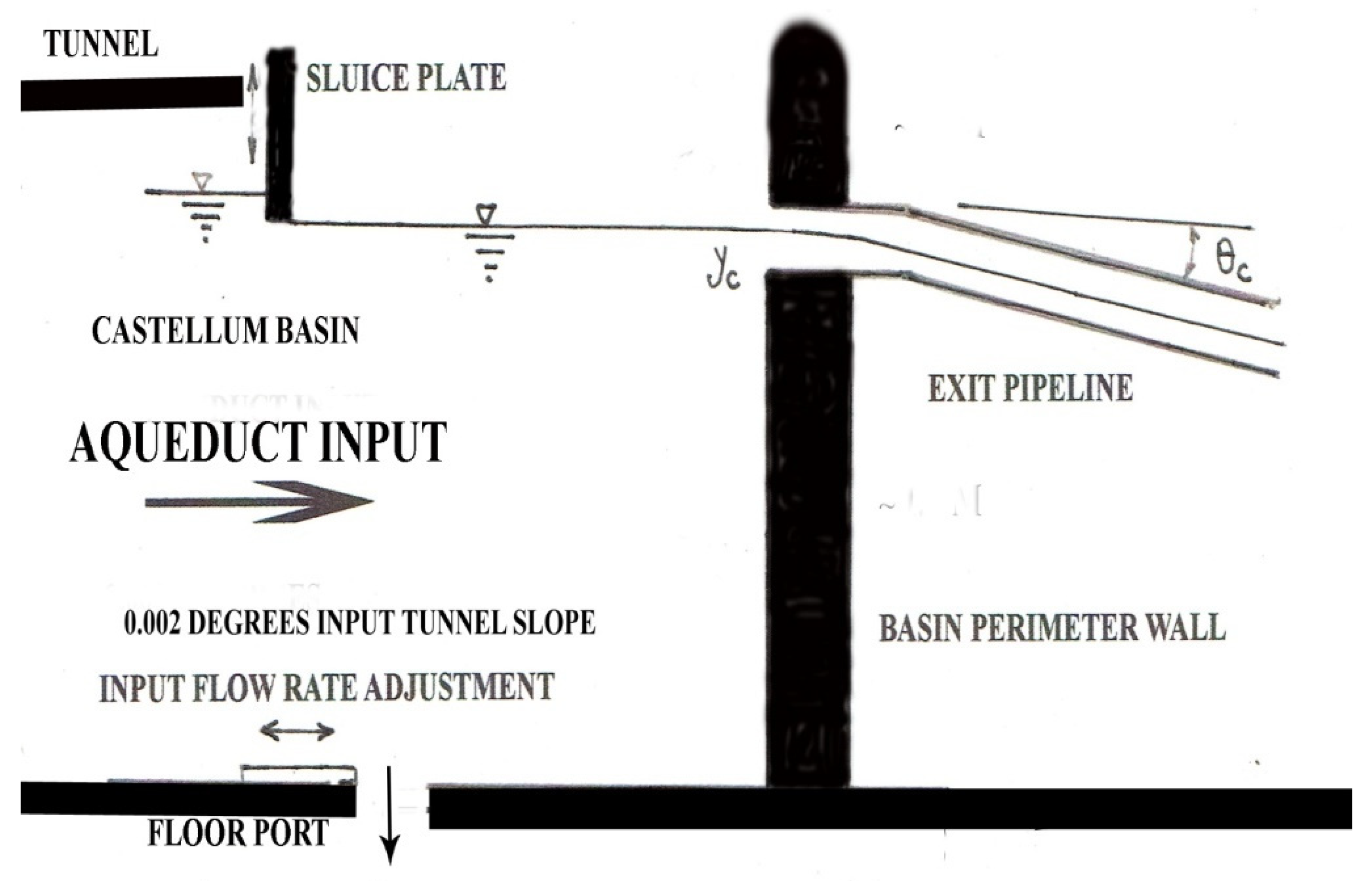
It is estimated that the aqueduct supplied the city with a minimum of 20,000 m3/24 h to a maximum of ~40,000 m3/24 h and that water took 28 to 32 h to flow from the Uzés spring source to the city [2,5]. The different limits in aqueduct flow rate reflect the seasonally variable spring discharge rate dependence upon groundwater recharge from infiltrated rainwater and received groundwater from surrounding infiltration areas. The castellum was designed for use at the maximum 40,000 m3/day flow rate that the Uzés spring source could supply on a steady basis—this being necessary to provide sufficient water for the large city population. Average water velocity was on the order of ~0.5 m/s according to one estimate [2] corresponding to the total maximum flow rate of ~40,000 m3/day. Aqueduct water arrived to the castellum—an open, shallow, circular basin ~5.5 m in diameter by ~1.0 m deep (Figure 3, Figure 4, Figure 5 and Figure 6)—and was surrounded by a (now lost) balustrade within an enclosure under a small, but elaborate, pavilion. When the castellum was first excavated, traces of a tiled roof, Corinthian columns and a fresco decorated with fish and dolphins were discovered in fragmentary condition. As to details of the construction of the castellum, adjoining curved stone slabs (Figure 3, Figure 4, Figure 5 and Figure 6) lined the receiving basin inner rear wall and, for the 10 basin wall pipeline ports, large arced adjoining stone blocks were pierced by 10 circular openings to accommodate pipeline insertion with leakage prevention cementing. The three floor ports were carved through the stone floor with right angle turn passageways below the floor permitting horizontal pipelines to emerge from outside the basin (Figure 5 and Figure 6). The basin floor has an outer rim upon which the arched basin wall blocks were placed. Although not apparent from the current state of the castellum remains, likely a thin layer of bitumen (or cement) between basin blocks provided leakage protection. The entry slope of the supply tunnel (0.002°, Figure 7) was vital to lower aqueduct water velocity and raise its height prior to basin entry; further flow area expansion from the narrow tunnel entrance opening into the wide basin further lowered the water entry velocity to the multiple basin wall pipelines. A (now lost) movable sluice gate (Figure 3, Figure 4 and Figure 5) regulated the basin water height into the 10 basin wall pipelines and played a vital design role in the operation of the castellum. Conjecture as to the design and function of the entrance sluice gate structure [2,3] prevails with no current resolution as to the design intent of its function to regulate castellum water height and velocity—the resolution of this issue is addressed in subsequent sections. A series of holes penetrating the top plate of the entrance structure exist [2,3] but as to the sluice plate lifting mechanism controlling the water entrance opening height, no current information exists.
The precise control and regulation of the maximum design flow rate from the aqueduct to the castellum was an important Roman design consideration to avoid basin spillage from the low wall height of the castellum basin and overflows from the aqueduct and supply channels. As the cross section of all channels was rectangular with a constant base width, local variations in flow rate from intercepted local rain storm runoff that would cause water height changes in the low slope channels were anticipated by Roman engineers by local height increases in the channel walls where spillage was likely to occur. Although water containment in channels during rainfall events was anticipated by the channel wall height design, the use of the three castellum basin floor ports to dispense excess water arriving to the castellum over the design flow rate kept the basin from overflowing thus maintaining its aesthetics even during rainfall events.
3. The Castellum Floor Ports: Hydraulic Design Considerations
Aqueduct water entered the castellum through a rectangular tunnel opening, 1.2 m wide by 1.1 m high (Figure 3, Figure 4, Figure 5 and Figure 6), and circular holes in the basin wall, each ~40 cm in diameter, give indication of the pipeline dimensions that directed water into the 10 basin wall pipelines. The three floor pipeline ports (Figure 6) if fully open, presuming a continuous aqueduct water supply, would induce a vortex over each floor entrance port inducing rotation of water in the basin [7]. This effect would alter the equal distribution of the water flow into the 10 wall ports. As this effect would influence the 10 pipeline design, the three-floor port opening cover plates would have been used sparingly for input flow rate regulation to produce near equalization of flow into the 10 separate pipelines. This requirement then mandated a castellum design that would closely regulate the aqueduct input flow rate to closely match the sum of output flow rates from the 10 basin wall pipelines with only minor flow rate corrections provided by the three-floor port opening areas. The rotating flow in each floor pipeline, given its passage through elbows below the basin floor (as Figure 5 indicates) would transition pipeline entry full flow to partial flow within the sloped pipeline extensions due to gravitational acceleration increasing pipeline flow velocity and lowered pipeline water height. Here a pipeline cross-sectional area fully occupied with water is denoted as full flow; a pipeline cross-sectional area partially occupied with water is denoted as partial flow. For high speed flow in highly sloped pipelines emanating from the castellum with significant internal pipeline wall roughness, a hydraulic jump may occur downstream in the pipeline. Between entry full-flow and downstream post-hydraulic jump full-flow regions, a partial vacuum region exists in the intermediate partial flow region. Unless these regions within pipelines are relieved by upper pipeline holes to admit air at atmospheric pressure, flow delivery instabilities arise as air enters the floor pipeline inlet by means of an air-entraining vortex extending from the water basin surface [7] together with air entering from the pipeline exit (for either submerged or free overfall conditions) to relieve the partial vacuum region. A further source of flow instability arises from large internal pipeline roughness slowing flow velocity and raising its height to transition partial to full flow. As upstream water length buildup occurs ahead of the full-flow hydraulic jump water region, accumulated water mass weight suddenly overcomes frictional resistance and causes the elongated water mass to rapidly transfer out of the pipeline to freefall into a reservoir. This clearing effect then restarts the creation of another full-flow region leading to periodic flow delivery to a reservoir. These effects for both high and low speed entry flow to wall pipelines cause transient, oscillatory water motion in pipelines resulting in castellum basin water level oscillations and unstable flow entering into pipelines. These effects are largely governed by pipeline water entry velocity, pipeline slope and diameter, internal pipeline wall roughness, pipeline segment connection joint roughness and hint of the complexity that Roman engineers contended with to produce a castellum design providing stable flow to city destinations. As Roman engineers had concerns about flow instabilities that induced pipeline vibrations [8] that loosened connection joints between pipeline elements to cause leakage, flow stability concerns related to castellum design were a major problem to be addressed and eliminated by an advanced castellum design. As the elimination of transient flow instability effects was an important consideration in castellum design, Roman engineers required design considerations to eliminate pipeline flow instabilities that could propagate upstream to the castellum basin and disturb the aesthetics of the basin water surface. The design considerations would therefore involve in some way the use of the controllable three-floor port opening size selection together with solutions associated with pulsating flow delivery and uneven flow rate delivery to the 10 basin wall pipelines. Further design considerations involve design of specific pipeline slopes selected by Roman engineers to limit unsteady hydraulic jump formation and transient pressure pulses to induce steady flow in pipelines.
How a design solution was accomplished by Roman water engineers to deal with and eliminate these complex interacting hydraulic effects by innovative castellum and pipeline designs is described in following sections. Although it has been previously suggested that the three floor ports were mainly used for flooding the amphitheater for mock naval battles (naumachia) [3,6], the allowable flow rate through three bottom ports alone is far lower than the input flow rate from the aqueduct as derived in a later section. The three floor ports may additionally have served the purpose of continuous flows to important sites but are inadequate, by themselves, to carry the 40,000 m3/day aqueduct flow rate without several (or all) of the 10 basin wall pipelines simultaneously in use as a later section details. If aqueduct flow is diverted by blockage and flow diversion to the Alzon River for aqueduct cleaning and repair functions, then the bottom ports would well serve to completely drain the castellum basin after the water level falls below the 10 basin ports pipeline openings. Among the reasons for the use of the floor ports, the main function of the floor ports, used with partially open covers (Figure 6) during normal daily operation of the aqueduct, was to drain away excess aqueduct supply water to exactly maintain the design 40,000 m3/day input aqueduct flow rate as apparently this rate was critical to the hydraulic design of the pipeline system of the castellum.
4. The 10 Castellum Wall Ports: Hydraulic Engineering Design Options
Candidates for the pipeline types emanating from the basin wall ports are the (120A) centenum-vicenum with a diameter of 22.83 cm and inner cross-sectional area of 409.4 cm2 and the larger (120B) centenum-vicenum with an inner diameter of 29.5 cm and a cross-sectional area [3,4,9] of 686.6 cm2. To include known Roman pipelines allowing for pipeline wall thickness of at least ~2.54 cm, then several standard Roman pipeline sizes [3] are basin entrance flow candidates. In the discussion to evaluate their merits of different flow rate measurement devices available to Roman water engineers, calices mounted in a horizontal pipeline section are considered as they are typical of Roman practice for flow rate measurement and can be used to regulate and/or limit flow rates when used as chokes (Figure 6b). In this figure, a typical calyx placed on the left is adjoined to a pipeline shown to the right. Flow direction is from left to right.
A table of calyx sizes and the use of a calyx–pipeline connection [3,10] in the 50, 80 and 100 digit sizes with diameters of 27.8, 45.5 and 57.4 cm, respectively, may have been considered by Roman water engineers to regulate the amount of water flowing in different pipelines to different destinations with different prescribed water needs. While Roman pipeline types have known standards [3,4,9], large bronze calices placed directly into the 10 basin wall entrance holes were a design option to match the sum of pipeline flow rates to the aqueduct flow rate input. Given that calices work only under full-flow conditions, their use by Roman engineers in the castellum pipeline entry ports may have appeared useful for precise flow rate delivery to destination sites given that full flow at basin wall pipeline entrances could be maintained by means of a horizontal pipeline elements before pipeline declination slope continuance converted full to partial flow in pipeline extensions to the lower city. This design option would require that the sluice gate was fully open and that basin wall height exceeded the observed wall height shown (Figure 3, Figure 4, Figure 5 and Figure 6) to ensure full-flow entry into basin wall pipelines. The higher basin wall height design would require a higher elevation of the tunnel supply line and an even lower aqueduct slope leading to the tunnel. Sustaining entry full flow into basin wall pipelines would rely on constant water height in the elevated wall height basin just to support full-flow calyx usage. The advantages of full entry flow incorporating calices placed at the start of horizontal piping branches with markings to indicate that the output flow rate (in quineria) had yet a further disadvantage beyond height reconfiguration of the inlet tunnel. Calices used at the entrances of all 10 basin wall pipelines theoretically provided the sum of their flow rates and therefore were vital to match the aqueduct design flow rate. As calyx sizes appropriate for the ~30 cm inner diameter pipelines give erroneous flow rates based on the nozzle diameter rather than the square of the diameter appropriate to the cross-sectional area of the nozzle, the correct flow rate prediction would ultimately be a problem if installed due to the inaccuracy of calyx flow rate measurement. An analysis of calyx use [10] describes inaccuracies associated with large flow rate measurements. Since accurate flow rate measurements were necessary in a system design to balance aqueduct input exactly to 10 pipeline water transfer output, calyx flow rate inaccuracies would compromise the castellum design that requires precise measurements of flow rates particularly if the use of only calices for flow rate determination precluded the use of the three floor ports as a flow rate adjustment. If the calyx design option were pursued then major redesign and reconstruction of the castellum would follow upon flow rate proof tests using the full aqueduct design flow rate. As the existing castellum design is vastly different from that utilizing this design option, this indicates that Roman engineers were aware of the precision difficulty of calyx water measurement devices and the near impossible reduction in the lead-in aqueduct slope and tunnel elevation underlying calyx usage. As the existing tunnel entry slope is already small (0.002°, Figure 7), an even lower slope design would severely challenge surveying accuracy measurement capability as well as requiring significant modification of the aqueduct slopes upstream of the tunnel.
Apparently the concept of water velocity and its measurement were recognized as important to determine flow rates but such considerations were not readily available to Roman engineers due to lack of precise time measurement devices [1,3]. From these considerations, it was apparent that a calyx-based design option was not practical and Roman engineers would need to choose a more refined design option that eliminated problems associated with the calyx design option as well as flow instability problems. What then was the final Roman castellum design that solved all the problems mentioned to match aqueduct input and pipeline output flow rates exactly?
As no traces of actual pipelines or calices exist at the present castellum site, pipeline connection details, as well as the exact pipeline diameter used, remain conjectural. Nevertheless a reasonable estimate of pipeline diameter may be made for flow rate estimation based upon the castellum retaining wall diameters shown (Figure 3, Figure 4 and Figure 5) and the three-floor port geometry (Figure 6). Based upon the above discussion, for the three castellum floor ports used to rapidly flood the nearby amphitheater for naumachia, this function would require the addition of several (or all) of the 10 wall outlet ports to work in conjunction with the floor ports to accommodate the 40,000 m3/day aqueduct flow rate. The naumachia function would necessitate that valves were available in basin wall pipelines to redirect additional flow to the amphitheater. That such large valves were in the Roman engineer’s purview has been demonstrated [9]. For the present analysis, however, it is assumed that all 10 side wall ports were in continuous use but not the three floor ports (except for fine adjustment of the input 40,000 m3/day flow rate to wall pipelines)—this conclusion underlies pipeline flow rate results to follow.
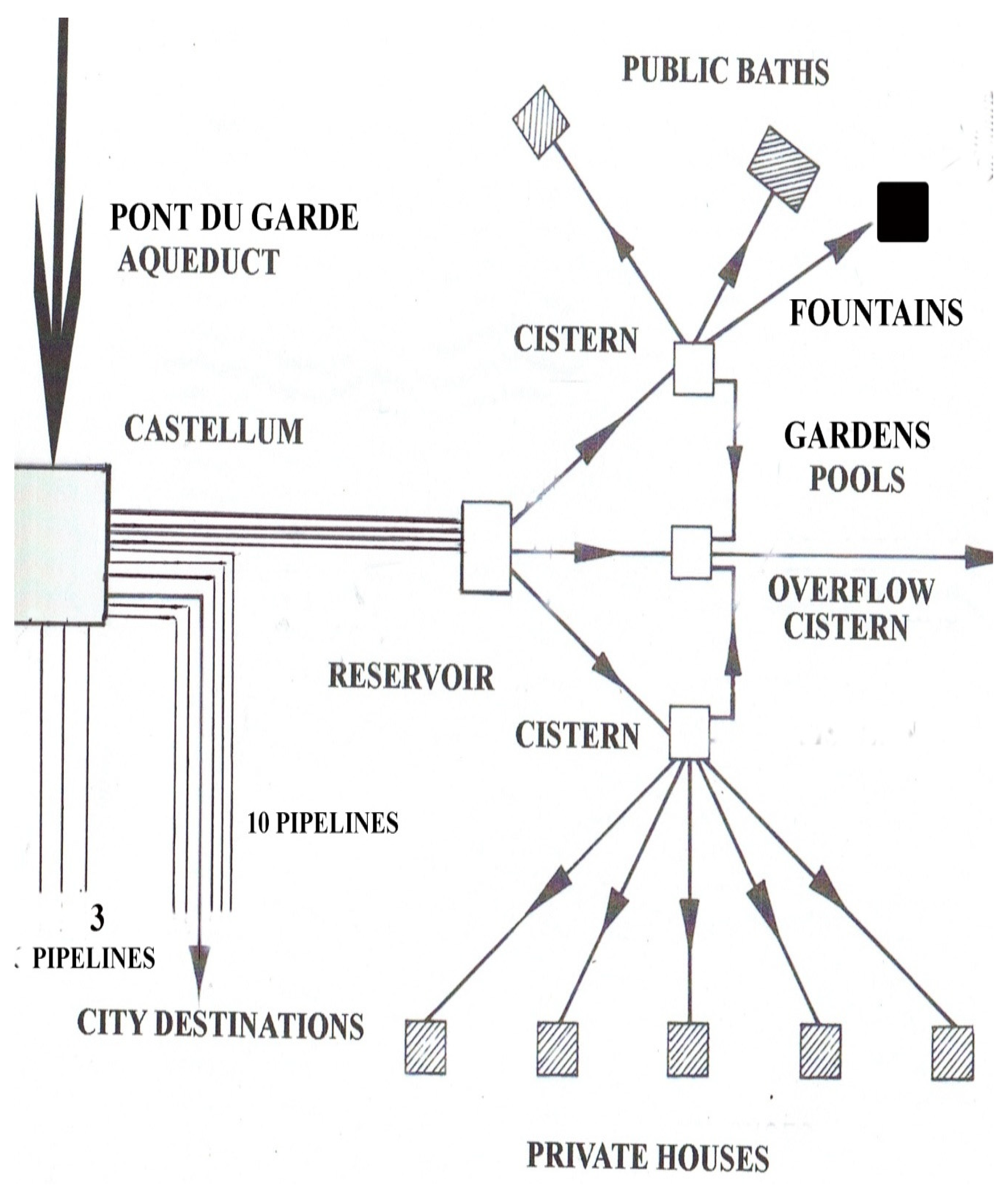
Since the castellum was elevated well above the Roman city and few traces of the multiple water destinations and connection pipelines now exist, it may be assumed that pipeline lengths were on the order of a fraction (or more) of a kilometer from the castellum to different city destinations. A typical Roman arrangement of pipelines from the castellum to a lower reservoir (Figure 8) would be designed to regulate flow to destination sites. Each city destination may have had time variable flow rate requirements (particularly baths and private houses) from cisterns and stilling basins so that overflow cisterns were necessary to captures excess water flows and direct water to collection basins serving gardens, pools and storage basins that did not require steady water input. Similar designs to those shown (Figure 8) were in use at the Roman site of Pompeii [4,11]. Based on this design complexity for a city water distribution system, emphasis on stable pipeline flow delivery would be an important consideration that minimized maintenance and the use of supplemental downstream settling basins and thus was a prime consideration inherent to the castellum design.
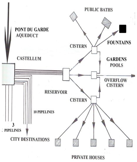
Figure 8.
Aqueduct supplied water to the castellum showing the redistribution network structure typical of Roman cities.
The early writings of Vitruvius and Frontinus on Roman hydraulic engineering practice [12] are replete with pre-scientific notations of hydraulic phenomena related to flow velocity, flow rates, time and hydrostatic pressure that were used for water flow rate measurement. On this basis, there is much to recommend Roman hydraulic engineering practice as largely based on an observational recording basis based on pipeline slope effects on flow delivery as opposed to results derived from theoretical calculations. The basic problem in determining flow rate was the accurate measurement of time and water velocity which eluded precise Roman definitions as indicated by Roman water administrator’s book descriptions. In this regard, Greek hydraulic engineers demonstrated progress in measuring average water velocity and flow rates appropriate to fountain and water outlet designs at Priene [13]. In this case, a large basin of known volume (V) was filled by water flow from a level pipeline; a time measuring device (water clock, candle burn time, as examples) provided an estimate of the time (T) to fill the basin. The flow rate (Q) for the pipeline is then Q = V/T. This same methodology could be used for different calices mounted on a pipeline to determine an estimate (or correction) of their quineria flow rate marking if indeed this was part of Roman technology yet to be elucidated.
To understand pipeline flow phenomena dependent upon pipeline slope and pipeline-basin attachment choices, discussion is next focused on the hydraulic positives of an alternate design choice for flow rate measurement. Here the castellum design contains elements of advanced Roman hydraulic technology thoughtful of the effects of pipeline slope choices and effects derived from knowing how to produce stable flow rates. From the analysis to follow, design elements noted in the actual castellum construction are revealed that demonstrate the design of an optimum water delivery system that effectively matched aqueduct input flow rate to the castellum output flow rate, produced maximum flow rates with pipelines to limit the number of pipelines used and eliminated flow instability problems.
5. Toward the Optimum Castellum Design
Many Roman pipeline designs transferring partial flow had top hole openings to eliminate partial vacuum regions [14,15] (pp. 314–320 [15]) but use of this feature for the present case is not known due to absence of pipeline remains. In the absence of pipeline top openings, transient air ingestion at the pipeline exit port, or from the basin water surface, occurs to counter a partial vacuum region that induces pulsating forces acting on pipeline joints that promote leakage. Such partial vacuum regions occur when subcritical entry full flow transitions to a partial critical (or supercritical) flow in the declination sloped pipeline continuance from an initial horizontal pipeline section; when a downstream hydraulic jump occurs due to inner pipeline roughness, then the partial vacuum region is trapped between these two separating flow conditions. This condition exists for either free or submerged pipeline exit conditions into a reservoir as for either case, atmospheric air enters the entrance and exit regions of the pipeline to counter the partial vacuum region inducing transient flow instabilities as the hydraulic jump location is unstable due to air ingestion rate differences and the transient, variable pressure and size of the partial vacuum region. A further contribution to flow instability occurs when the upstream size of the subcritical hydraulic jump region increases to a point where the weight of this region causes a flushing of the region out of the pipeline exit; when this flushing is done, the previous flow conditions restart once again inducing flow instabilities. When post-hydraulic jump subcritical pipeline flow delivery to a reservoir (Figure 8) is erratic, induced flow oscillations propagating upstream in a flow pipeline cause erratic motion of water flow to adjoining distribution basins as well to castellum basin water thus destabilizing smooth flow delivery and cancelling water basin aesthetics by surface wave occurrence. As flow stability considerations were known to Roman engineers, their castellum and pipeline designs must reflect a design that would eliminate erratic flow oscillations in pipelines and in the castellum basin and provide resolution of all flow instability problems through knowledge of preferential pipeline slopes in some manner. A further consideration known to Roman water engineers was that maximum pipeline flow rates are associated with critical partial flow—not full flow—conditions and that this is related in some way to the declination slope of a pipeline. Noting that the pipeline entrances are very close to the top rim of the castellum basin (Figure 6), this feature indicates that the castellum design reflects knowledge of inducing partial critical flow into pipeline entrances and this is related to achieving total maximum flow rate through the 10 pipelines equal the input aqueduct flow rate in an optimum manner. If pipelines could be designed to transmit the maximum flow rate possible, then this would reduce the need for additional pipelines emanating from the castellum.
As a first consideration of the observed castellum design, the water height entering pipelines is controlled by lowering the sluice gate to precisely control the basin entry water height to the pipelines (Figure 9). Provided this water height from the basin bottom comes up to half the pipeline diameter, then from the aqueduct input flow rate of ~40,000 m3/day to the castellum, the average flow rate for a single pipeline is 1.63 ft3/s; for 13 ports open, the average single pipeline flow rate is 1.26 ft3/s. From hydraulic engineering theory [16], for D the pipeline diameter (~30 cm) and g the gravitational constant (9.82 m/s2), Q/D2 (g D)1/2= 0.29 for 10 open pipelines and 0.22 for 13 open pipelines. From [11], Henderson’s Figure 2, Figure 3, Figure 4, Figure 5, Figure 6, Figure 7, Figure 8, Figure 9, Figure 10, Figure 11 and Figure 12, yc/D = 0.5. This means that the yc critical depth entering pipelines, regulated by the height position of the sluice gate, is equal to half of the pipe diameter (Figure 12). Thus water enters the 10 wall pipeline entry ports at half the pipeline diameter height at critical (Fr = 1) Froude number [11,16,17,18,19]. The Froude number is defined as Fr = V/(g Dm)1/2 where V is water velocity, g the gravitational constant and Dm the hydraulic depth [11,12,13,19]. From critical entry flow, the continuance of partial critical flow in pipelines is determined by pipelines set at the critical slope range (θc, Figure 12).
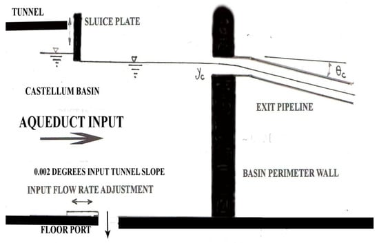
Figure 9.
Basin exit wall flow dynamics (not to scale).
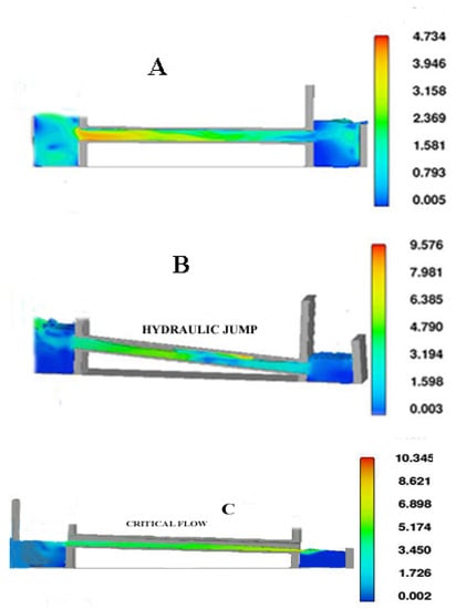
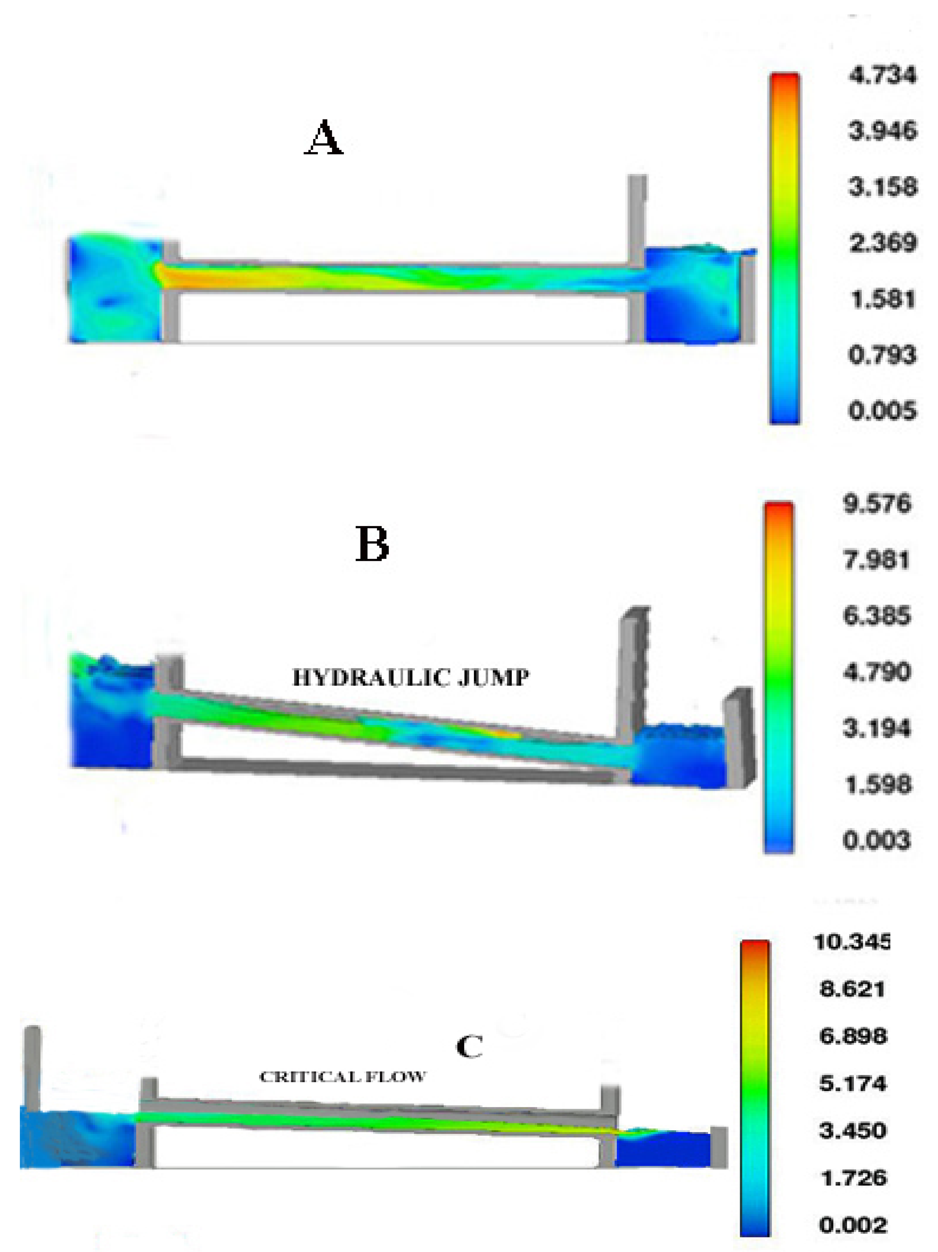
Figure 10.
FLOW-3D CFD calculation results for pipeline Cases (A–C). Velocity in m/s.

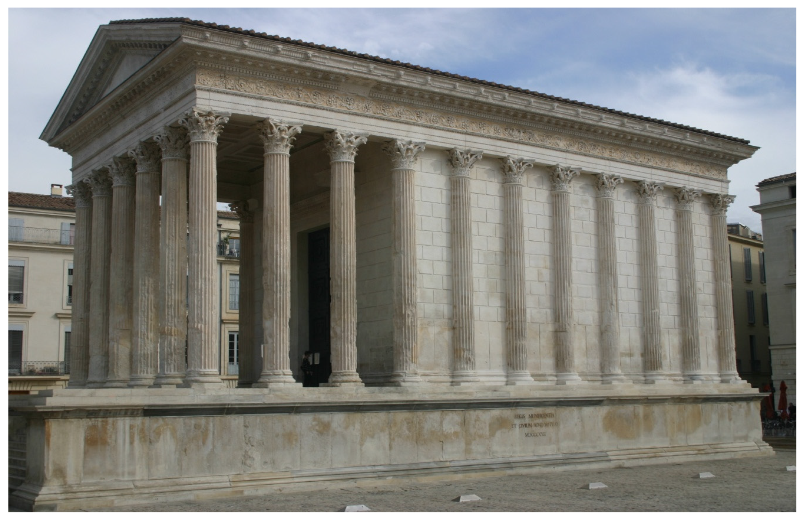
Figure 11.
The Maison Carré Roman Temple in central Nîmes.

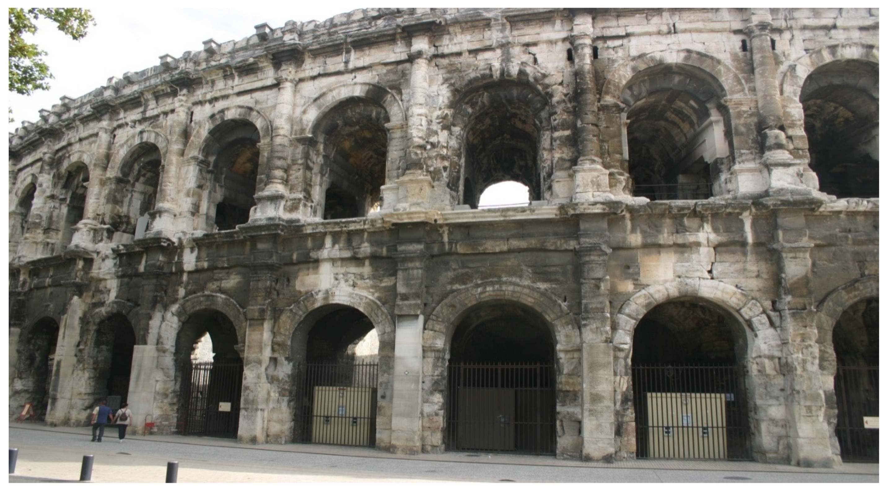
Figure 12.
The Roman amphitheater located in central Nîmes.
The physical significance of establishing critical flow conditions in pipelines [11,12,13,16,19] emanating from the castellum lies in the fact that when pipelines are set at a critical slope, this minimizes the energy expenditure to transport the flow at the highest flow rate. The lower the energy expenditure to transport pipeline flow, the less reliance on supplemental ways to increase flow rate such as an elevated castellum basin wall height and increased water height to provide additional hydrostatic pressure to increase flow rate. As partial critical flow can be maintained (or somewhat extended) over the entire pipeline length given smooth interior pipeline walls, atmospheric pressure exists over the partial flow from air entry into the open pipeline exit. Pipelines set at the critical slope are therefore free of hydrostatic pressure that would induce leakage under full-flow conditions. Most importantly, critical flow (Fr = 1) conditions throughout entire pipeline lengths produce the highest pipeline flow rate [10,15,16,17,18,19]. Pipeline designs that sustain flows equal to or close to partial critical flow (Fr = 1) over long distances would largely eliminate flow instability concerns from hydraulic jump creation as only a small water contact area with the interior pipeline wall roughness exists under partial flow conditions thus lowering flow resistance effects that would lead to internal hydraulic jump formation. As critical flow is maintained in critically sloped pipelines, no upstream influence from downstream resistance elements (pipe bends, contractions, bifurcations, hydraulic jumps) can propagate upstream to disturb basin water height and stability conditions [10,16,17,18,19]. Such considerations related to the effects of pipeline slope to produce stable flows must have been known to Roman engineers from observation of the many hydraulic engineering projects they implemented; in this regard, several elements of the pipeline system at Ephesus [14] constitute a prime example. With the advantage of flow stability derived from a critical flow design, the use of downstream accumulators, water towers, settling basins and open basin reservoirs and settling tanks (Figure 8) used to stabilize flow conditions between pipeline exit flows to different destinations with specific flow rate needs can be minimized. In the discussion to follow, the English unit system is used as this underlies many of the empirical hydraulic relations used in the analysis.
The critical, partial flow entry velocity for 10 pipes is Vc = (g yc)1/2 = 4.01 ft/s and 5.8 ft/s for the 13 ports open case. The Froude number is Fr10 ≈ 1 for the 10 port open case and Fr13 ≈ 1.3 for the 13 port open case. The important conclusion is that wall port entry Froude numbers are either near critical (Fr ≈ 1) or slightly supercritical (Fr > 1). Again, the importance of this design feature, as regulated by the sluice gate height position (Figure 12), is that with critical (Fr = 1) and near supercritical (Fr ≈ 1) entry port flows that continue critical (or near critical) in pipelines, this eliminates downstream resistance influence that may induce upstream flow instabilities and destabilize the input flow rates to the pipeline ports. This positive effect is induced with smooth interior wall pipelines with little if any connection joint roughness—an option likely available for optimum water transfer flow conditions to the city. This is a most important design feature of the actual castellum and its sluice gate regulation mechanism. In modern hydraulic terminology, upstream influence derived from downstream resistance obstacles does not occur for Fr = 1 critical or Fr > 1 supercritical flows [10,15,16,17,18,19]. The θc angle (Figure 10) is derived from the Manning equation [19] where n is an empirical resistance constant indicative of a likely worst case internal pipeline wall roughness (given here as n = 0.034) and connection joint roughness accumulated from the thousands of piping connection sections of ~0.5 m length that comprise long pipelines from the castellum to destination sites. Here Rh is the hydraulic radius given by the cross-sectional area of the critical flow (Ac) divided by its wetted perimeter. The critical pipeline angle θc is given by:
θc = tan−1 (n Vc/1.49 Rh2/3)2 = tan−1(n Q/1.49 AcRh2/3)2
Substituting, for the 10 basin wall ports open case, θc ≈ 4.6° and for the 13 port open case, θc ≈ 7.1° with an average value of ~ 5.8°. For the 3 basin floor pipelines closed, pipeline slopes emanating from the castellum should have declination slopes in the range of ~4.6° (or somewhat higher). For all 13 ports open, the pipeline declination slopes should be a bit higher at ~7.1° to maintain partial critical flow. As a later section demonstrates, the 10 basin wall pipelines set at θc are sufficient to transfer the 40,000 m3/day (1.41 × 106 ft3/day) aqueduct flow rate indicating the minimal use of basin floor pipelines for fine-tuning of the input flow rate to 40,000 m3/day. Thus the three basin floor ports are considered closed (or partially open) to fine tune the yc water height and design critical flow rate at pipeline entrances. When final destination site locations are distant from the castellum, pipelines emanating from the basin should have slopes in the ~4.6° < θc < ~7.1° range. The higher slope value is for high internal pipeline roughness over longer pipeline lengths that likely induce a downstream hydraulic jump (Case B, Figure 9) unless the use of smooth pipeline interior walls for longer pipelines is in place to maintain critical or near-critical flow advantages. Based on the surveying accuracies obtainable by Roman engineers [1,3,4,9] such slope accuracies are easily within their surveying capabilities.
6. Pipeline Destination Types Served by the Castellum
As critical pipeline slope configurations are observed as having flow stability and high flow rate benefits, the next task is to examine both critical and off-design, non-critical pipeline slopes that may occur if destination sites mandate higher or lower pipeline slopes to reach. As different pipeline slopes yield different flow rates, the task ahead is to determine what slope choices associated with different destination uses produce flow rates to match the 40,000 m3/day input aqueduct flow rate. Three possible pipeline configurations (A, B, C) determined by their slopes originating from the castellum basin wall are examined using FLOW-3D Computational Fluid Dynamics [20] CFD models (Figure 9). The use criteria involving different pipeline slopes are determined by computing the output flow rate (Table 1) from all 10 pipelines configured at different A, B or C slopes to determine whether the total output flow rate is lower, matches, or exceeds the input aqueduct flow rate.

Table 1.
Flow rate results for Cases A, B and C.
Figure 9 CFD model results show plane views of three-dimensional centerline interior pipeline flows for different pipeline slope conditions. The centenum-vicenum pipeline with a diameter of ~30 cm is used for the CFD model. The LHS model region represents the castellum entry port with a sluice gate position set to have critical entry flow to pipelines; the model RHS shows a submerged reservoir catchment at the end of a pipeline with a bottom drainage leading water by a further pipeline (or channel) to a destination site or intermediate reservoir. Although only a short pipeline length is illustrated in the models, the results are typical of flow patterns within longer pipelines as once a uniform flow profile is established, it continues over a long distance. Figures are characterized by an average full-flow 1.63 ft/s input velocity to a single basin wall pipeline; individual inlet velocities to pipelines are slightly different due to their relative locations with respect to the supply inlet.
The first figure (Case A, Figure 9) shows flow velocity conditions for a near level pipeline leading from the castellum. This configuration would provide water to hillside housing located at approximately the same height as the castellum) and water supply to upper-level reservoirs designed to store water at night to later discharge water through additional pipelines to sites with large, immediate water demands (such as baths) exceeding the continuous aqueduct supply rate over a given time period. Flow velocity is low in the near level pipeline due to full-flow wall friction effects and, for the low velocity subcritical (Fr < 1) flow, upstream influence exists so that distant exit reservoir flow stability conditions play a role in determining the delivery flow rate. This usage would require upper-level reservoirs to store water so that when fully charged, valves on pipelines to destination baths would open and have drainage rates higher than the aqueduct supply rate. Once water was delivered, then valves were closed and reservoirs refilled. This cyclical use could be made consistent with bath water change timing provided near-horizontal piping has the capability to transfer water at the aqueduct supply rate—a question addressed in the next section.
The second figure (Case B, Figure 9) represents pipeline slopes exceeding the optimum pipeline critical slope. Pipelines at these slopes are consistent with the height difference and the distance between the castellum and some of the nearby flat areas of present day Nîmes that once held the streets of Nemausus. Initial entry port flow is full subcritical flow and, at a downstream location, partial supercritical flow develops in the pipeline until a hydraulic jump (HJ) occurs due to large internal pipeline friction effects at high water velocity converting supercritical partial (Fr > 1) flow to subcritical (Fr < 1) full flow. As Figure 9, Case B indicates. A smooth internal pipeline wall would delay the appearance of a hydraulic jump but for the present example case, very rough pipeline internal walls and connection joints are assumed (for smooth wall roughness, θc values would decrease). For significant internal wall roughness, an internal hydraulic jump is created isolating a partial vacuum region between full entry and post-hydraulic jump flow regions as previously noted. If openings were placed along piping top regions over the partial vacuum region, then a stable flow rate would be enhanced. Again, as no extant pipelines exist, the presence of pipeline top openings is conjectural but well within Roman technology as observed on Ephesus pipelines and the Laeodocian site [3,4,15]. Pipeline designs with Case B flow characteristics without a terminal stilling basin would be devoted to lower priority sites that do not require a stable water delivery rate such as gardens, reservoirs, latrine flushing channels and intermittent household use. Other uses may include pipeline water transfer to fountain houses that have multiple chambers supporting different hydrostatic head values [4] to transfer water at different flow rates to different destinations; such terminal fountain houses were likely part of a city flow network. Figure 10 and Figure 11 show typical Roman flow destinations still existing in present day Nîmes served by one or more of the castellum’s 10 pipelines. The Maison Carré Roman Temple to Apollo (Figure 11) constructed in the period 10–16 BC required a later water supply addition for ritual and ceremonial purposes; the second century AD Roman amphitheater (Figure 12) also required ample water supply for large public gatherings for events and spectacles and likely required the output of several of the castellum pipelines for this purpose. This could be accomplished by water storage in lower reservoirs elevated above the amphitheater level with suitable valve systems to control the flow rate to drinking fountains and water basins within and adjacent to the amphitheater.
For display fountains, nymphaea, high-status administrative buildings, and elite residential areas, critical flow designs (Figure 9, Case C) are preferred as all destinations would benefit from a stable, high delivery flow rate without the use of intermediate distribution reservoirs and stilling basins (Figure 8) and thus have an immediate economic benefit to reduce construction costs and system complexity. Case C represents the optimum critical slope condition for which the volumetric flow rate is the maximum possible and, as an air space exists over a long stretch of the pipeline length, pressurized pipeline leakage is largely eliminated thus producing lower maintenance requirements. This pipeline choice can be used for city sites reachable in the slope range ~4.6° < θc < ~7.1° depending on the number of basin ports open. This consideration helps city planners place structures requiring large flow rates and helps determine the placement of main reservoirs (Figure 8) from which additional pipeline branches emanate to destination sites. Given that deliberate use of the Case C pipeline design was within Roman hydraulic engineer’s knowledge base, it may be surmised that the lower priority pipeline slopes of the Case B type required a stilling basin attachment before distribution to other destinations (Figure 8) and would be of secondary use while the higher priority pipelines requiring a high, steady flow rate directly to a destination site of the Case C type were preferable. As the slope difference between Cases B and C is small and direct use of a Case C design with a precise slope has the constraint of direct access to a destination site by a pipeline of that slope, most probably Roman engineers constructed pipelines as close as possible to a critical slope design to obtain the many benefits listed.
Based upon CFD results, an estimate of the volumetric flow rate is next made for each of the Case A, B, and C pipeline designs for 10 basin ports open and results compared to the aqueduct input flow rate of 40,000 m3/day. If the input aqueduct flow rate exceeds any of the Case A, B and C 10 pipeline outlet flow rates, then such pipeline configurations are not feasible as castellum basin overflow would result. If the input aqueduct flow rate is equal to the total out flow from 10 pipelines for pipeline configurations given in Cases A, B or C, this gives indication of a probable pipeline slope usage. Here the pipeline slopes range from ~1.0 degree (near horizontal) for Case A, ~7.1° slope for Case B, to a critical angle slope for Case C of ~4.6°. Table 1 summarizes the CFD computed output flow rates for A, B and C pipeline configurations.
For Case A, full flow exists (Figure 9) in near-horizontal pipelines with a submerged exit into a reservoir. For Case B, full flow into the pipeline entrance transitions to supercritical, partial flow on a steep pipeline slope; a hydraulic jump is formed within the pipeline induced by the deceleration of flow by pipeline wall frictional effects together with submerged exit flow into a reservoir. For Case C, critical flow exists in a pipeline at a ~4.6° slope yielding the maximum pipeline flow rate. The high water velocity is consistent with low partial flow height thus lessening the water contact area with the rough interior surface of the pipeline—this largely minimizes the creation of a hydraulic jump from water-wall frictional effects. The pipeline exit flow is assumed to be free fall into a receiving reservoir.
From Table 1, Case A low-slope pipelines appear to be of minor (or no) use as the total of 10 pipelines open (three bottom ports closed) permit a much lower output flow rate (17,200 m3/day) through all pipelines than the input aqueduct input flow rate of ~40,000 m3/day. Even with all 13 ports open, the output flow rate of 22,400 m3/day is well below the input 40,000 m3/day aqueduct flow rate. The interpretation is that the input aqueduct flow rate far exceeds the capability of Case A near-horizontal pipelines to transport such high flow rates. The use of many near-horizontal pipelines filling high-level reservoirs then appears not to be the principal design intent of the castellum.
For three bottom ports closed, the calculated Case B flow rate is ~39,600 m3/day which is close to the estimated aqueduct flow rate of ~40,000 m3/day. This close flow rate matching produces a steady water height in the castellum that guarantees steady flow throughout the water distribution system; here partially open floor ports are useful to exactly match flow rates (Figure 10). This close match signals the Roman engineer’s design intent of the castellum to provide water to city distribution locations by pipelines of slopes in the ~4.6° < θc < ~ 7.1° range. Although a hydraulic jump may occur due to wall roughness effects, it may largely discounted if Roman engineers utilized smooth inner wall pipelines to promote flow stability. The near flow rate match indicates the hydraulic technology to make a castellum design to closely match the input aqueduct flow rate in advance of the building and flow rate testing of installed pipelines. For a 0.25 km long pipeline sloped at ~4.6°, the altitude drop from the castellum to the city area is ~18 m which is a reasonable value given a personal downhill walking tour from the castellum to the city center.
Case C critical flow pipelines appear to have the delivery capacity close to the ~40,000 m3/day aqueduct flow rate and preferably would be in use as there is only a minor slope difference between Cases B and C. Since Case C slopes would reduce the occurrence of an internal pipeline hydraulic jump, this design would be preferable, but not always achievable, due to surveying accuracy constraints or destination site requirements that dictate pipeline lengths and slopes. The critical slope on the order of ~4.6° may have played a role in locating city structures that demanded rapid, stable transfer of water, such as nymphaea and elite housing with internal water display structures. Given the ~4.6° pipeline slope and considering a height difference from the castellum to a potential city level reservoir, the pipeline lengths would be on the order on ~0.25 km; this may influence the placement of intermediate reservoirs.
From Table 1, the likely pipeline candidates in use were Cases B and C examples used in conjunction with three partially open (or closed) floor ports. The Case B flow delivery capacity approximates the aqueduct water supply water of ~40,000 m3/day. Case B and C designs are practical for 10 basin wall entrances operating continuously as pipeline slopes on the order of ~4.6° to ~7.1° guarantee stable (or close to stable) water transfer from the high elevation castellum to lower city level sites. The remaining three floor ports, if open, would rapidly drain the castellum as flow from all 13 ports exceeds the input aqueduct flow rate as Table 1 indicates. It is important to note that for Case B and Case C the pipeline transfer flow rate approximates the input aqueduct flow rate and that a steady, smooth water height is maintained in the castellum basin close to the basin top rim which was the aesthetic design intent of Roman engineers. For situations for which several (but not all) of the pipelines are at the critical slope, then a mixed array of pipeline slopes with more than, less than, and equal to the critical slope exist. Here the use of the three floor ports for flow rate adjustment would be critical to match the aqueduct input flow rate to the sum of output flow rates from the castellum to maintain constant castellum water height.
7. Off-Design Hydraulic Function
To this point, flows exceeding the input design flow rate are adjusted back to the design flow rate by adjustable floor port openings. For cases for which the flow rate is somewhat less than the design maximum, flow into the castellum basin will back up in height until the water height reaches the basin wall lower pipeline port openings. This discharge causes an upstream transient water height wave to propagate upstream in the low slope aqueduct channel upstream of the entry port to the castellum basin. As the transient water height begins to discharge into the castellum basin wall ports, oscillatory wave motion on the basin water surface will follow and propagate upstream into the supply aqueduct channel. This effect induces a periodic discharge into the basin wall pipelines, destroying the desired aesthetic effect of a smooth castellum basin water surface as well as inducing periodic flow into the pipelines that, given their long length, may transition partial to full flow due to pipeline interior wall roughness. This flow condition then has transient flow instabilities that affect the stability and aesthetics of the water in the receiving castellum basin and the downstream reservoir. Provided baffles are installed in the reservoir, them flow oscillations can be damped thus providing a stable flow rate to further downstream destinations. On this basis, the importance of maintaining the design flow rate is of prime importance as lower flow rates flow rates fail to accomplish the main purpose to provide adequate water supply to the city.
For cases for which aqueduct flow into the castellum basin is significantly less than the design flow rate, again upstream flow backup occurs until basin water height reaches the lower parts of the basin wall port openings. In this case, a stable trickle flow occurs into the pipelines with no instabilities occurring. Thus for either of the off-design situations, the castellum still functions to provide limited water supply to final destinations but at an aesthetic disadvantage.
8. Conclusions
The challenge to Roman engineers was to eliminate sources of flow instability by a castellum and pipeline design that transferred input aqueduct water at the highest stable flow rate possible through the 10 basin wall pipelines. The castellum design demonstrates Roman hydraulic knowledge at work in many ways—particularly in the use of a shallow, wide-diameter basin with the retaining basin wall slightly higher than the top of the pipeline entrance ports. This design initiates basin input flow from the aqueduct water entrance port into pipeline entrances at critical, partial flow conditions; its continuance as critical or near-critical flow is guaranteed by appropriately sloped pipelines to important city destinations. Given Roman experience with flow instabilities associated with pipeline internal wall roughness, it is likely that selection of smooth interior walls was the design preference. As the 10 pipeline cumulative flow rate approximates the maximum aqueduct input flow rate for Cases B and C, it is clear that the design intent of the castellum recognized advantages in selecting pipeline slopes to largely limit or eliminate hydraulic jump occurrence—this occurs when Case B near-critical flow conditions apply. As the basin wall height is close to the top of the pipelines; partial entry flow into the 10 wall pipelines was the design intent of Roman engineers; this made possible by the positioned height opening of the sluice gate. Given the pipeline critical or near-critical slope range of ~4.6° to ~7.1°, CFD results indicate that the 40,000 m3/day aqueduct flow rate is transferred at the near maximum pipeline flow rate by Case B and C designs. Note that this θc range is only 2.5° difference to ensure critical or near-critical pipeline flow. This matching is necessary to maintain a constant water height in the castellum and minimize the number of pipelines that can successfully transmit the aqueduct input flow rate. If critical and near-critical designs were not considered, then a castellum design with more than 10 basin wall pipelines would be necessary thus increasing the size and cost of the present design.
The conclusion of the present analysis is that Roman hydraulic engineers designed the castellum to match the input aqueduct flow rate to the 10 basin wall pipeline transfer flow rate by employing a critical and/or near-critical flow conditions. This option presumes a series of lower-level reservoirs at pipeline termination locations that support pipeline branches to different sites (Figure 8). As different pipeline flow rates occur within different pipelines with slopes at critical, near-critical and higher and lower slopes to supply spatially dispersed sites with different water demands, this necessitates partial opening of the floor ports to match the design water output to the given aqueduct input flow rate. For situations where the flow rate may exceed 40,000 m3/day, again the floor ports’ cover openings can be adjusted to eliminate excess flow over the design maximum of 40,000 m3/day that the critical and near-critical pipelines can convey.
Provided the 10 basin wall pipeline slopes can be maintained in the ~4.6° to ~7.1° slope range, this design option provides the most efficient and stable way to match the aqueduct input flow rate and eliminate maintenance problems associated with flow instabilities inducing pipeline joint leakage. The totality of the Pont du Gard aqueduct and castellum design demonstrates a coordinated engineering design of all subsidiary hydraulic components that supply the castellum.
In summary, the total Pont du Gard aqueduct and castellum design includes (1) flow rate regulation through a far upstream intersecting side channel to drain away flows exceeding the design intent aqueduct input of a ~40,000 m3/day flow rate. (2) The partially open bottom three castellum floor drains that can be used to remove excess aqueduct input water to achieve the 40,000 m3/day design input flow rate to the castellum. (3) Use of the low aqueduct slope preceding the castellum tunnel chosen so that pipelines emanating from the basin wall can be appropriately sloped to provide the pipeline maximum flow rate consistent with the supply aqueduct flow rate to the city below—this slope range is on the order of ~4.6° to ~7.1°, and this condition largely explains why the terminal channel slope to the castellum entrance port tunnel is very low to facilitate critical pipeline slopes to destination city sites. (4) Aqueduct channel width, depth, side wall height and slope dimensions were designed to contain the design intent of a ~40,000 m3/day flow rate without spillage as well as rainfall-induced temporary water flow rate overages. (5) The low channel slope entry (0.002°) to the castellum is designed to slow water velocity and raise its height to the near top of the supply tunnel (Figure 3 and Figure 4). (6) The sluice gate (Figure 10) height adjustment is used to produce the desired basin entry pipeline water critical height to permit critical (or near-critical) entry flow to pipelines. (7) The ~40,000 m3/day aqueduct input flow rate closely matches the 10 basin wall pipelines output flow rate (with floor ports closed) under Case B near- and Case C exact-critical flow conditions, Table 1). This flow rate match condition is necessary to maintain a smooth, constant operational water height in the castellum basin. (8) Critical flow conditions at 10 pipeline entrances are produced by making the sluice gate opening height equal to half the pipeline diameter (Figure 10), and this ensures critical entry flow to pipelines [16,17,18,19]. Critical and near-critical flow in pipelines is continued by pipeline slopes of ~4.6° to ~7.1°. Note that this pipeline slope range is approximately equal to the hill slope angle down to the main flat part of the city showing the design intent to place the tunnel at a specific height to achieve this result. (9) Production of critical or near-critical flow conditions in pipelines eliminates the influence of downstream flow resistance elements (bends, chokes, pipeline angle change, hydraulic jumps) that can propagate upstream to produce unstable, transient oscillations and unstable flow delivery from, the castellum basin. (10) The use of the critical and near-critical flow pipeline slope design produces the maximum, stable flow rate possible in pipelines and reduces pipeline joint leakage as an atmospheric airspace exists over the partial critical flow eliminating pressurized full-flow conditions that induce pipeline joint leakage; critical and near-critical flow are maintained in the pipeline to produce the benefits indicated above. Note that if the pipeline declination angle is lower than the θc range (~4.6° to ~7.1°) then downstream disturbances can propagate upstream to cause unstable basin oscillations that destabilize steady state behavior and cause spillage from the top of the castellum rim. For pipeline declination angles greater than the θc range, upstream disturbances cannot propagate upstream but the output flow from the 10 basin wall pipelines is less than 40,000 m3/day. Based upon these many technical considerations inherent to the castellum design, the integrated, coordinated design of all components of the Pont du Gard aqueduct reflect Roman engineer’s hydraulic engineering knowledge and thus serve to add to the compendium of Roman practices and water engineering inventions thus far described in the open literature.
Funding
This research received no external funding.
Conflicts of Interest
The author declares no conflict of interest.
References
- Lewis, M. Surveying Instruments of Greece and Rome; Cambridge University Press: Cambridge, UK, 2001; pp. 181–188. [Google Scholar]
- Hodge, T. Roman Aqueducts and Water Supply; Bristol Classical Press: London, UK, 2011. [Google Scholar]
- Green, M. Dictionary of Celtic Myth and Legend; Thames and Hudson Publishers: London, UK, 1997. [Google Scholar]
- Sage, M. Roman Conquests: Gaul; Pen and Sword Books Ltd.: London, UK, 2011. [Google Scholar]
- Hauck, G.; Novak, R. Water Flow in the Castellum at Nîmes. Am. J. Archaeol. 1988, 92, 393–407. [Google Scholar] [CrossRef]
- Lugt, J. Vortex Flow in Nature and Technology; John Wiley & Son: New York, NY, USA, 1983. [Google Scholar]
- Nielsen, M. Pressure Vibrations in Pipe Systems; NYT Nordisk Forlag: Copenhagen, Denmark, 1952. [Google Scholar]
- Bennett, C. Frontinus: Stratagems and the Aqueducts of Rome; Harvard University Press: Cambridge, MA, USA, 1961. [Google Scholar]
- Herschell, C. The Water Supply of the City of Rome; New England Water Works: Boston, MA, USA, 1973. [Google Scholar]
- Ortloff, C.R.; Crouch, D. Hydraulic Analysis of a Self-Cleaning Drainage Outlet at the Hellenistic City of Priene. J. Archaeol. Sci. 1998, 25, 1211–1220. [Google Scholar] [CrossRef]
- Henderson, F.M. Open Channel Flow; The Macmillan Company: New York, NY, USA, 1966. [Google Scholar]
- Morris, H.; Wiggert, J. Open Channel Hydraulics; The Ronald Press: New York, NY, USA, 1972. [Google Scholar]
- Bakhmeteff, B. Hydraulics of Open Channels; McGraw-Hill Book Company: New York, NY, USA, 1932. [Google Scholar]
- Ortloff, C.R.; Crouch, D. The Urban Water Supply and Distribution System of the Ionian City of Ephesos in the Roman Imperial Period. J. Archaeol. Sci. 2001, 20, 843–860. [Google Scholar]
- Ortloff, C.R. Water Engineering in the Ancient World: Archaeological and Climate Perspectives on Societies of Ancient South America, the Middle East and South-East Asia; Oxford University Press: Oxford, UK, 2010. [Google Scholar]
- Flow Science, Inc. FLOW-3D/Version 7.0 Users’ Guide; Flow Science, Inc.: Santa Fe, NM, USA, 2019. [Google Scholar]
- White, K. Greek and Roman Technology; Cornell University Press: New York, NY, USA, 1984. [Google Scholar]
- Rasmussen, C. A Comparative Analysis of Roman Water Systems in Pompeii and Nîmes. Master’s Thesis, University of Arizona, Tucson, AZ, USA, 2017. [Google Scholar]
- Ven, T.C. Open-Channel Hydraulics; McGraw-Hill Book Company: New York, NY, USA, 1959. [Google Scholar]
- Ortloff, C.R. The Hydraulic State: Science and Society in the Ancient World; Routledge Press: London, UK, 2020. [Google Scholar]


Publisher’s Note: MDPI stays neutral with regard to jurisdictional claims in published maps and institutional affiliations. |
© 2020 by the author. Licensee MDPI, Basel, Switzerland. This article is an open access article distributed under the terms and conditions of the Creative Commons Attribution (CC BY) license (http://creativecommons.org/licenses/by/4.0/).