Article

Bedform Morphology in the Area of the Confluence of the Negro and Solimões-Amazon Rivers, Brazil

by
Carlo Gualtieri
1,*,
Ivo Martone
1,
Naziano Pantoja Filizola Junior
2 and
Marco Ianniruberto
3
1
Department of Civil, Architectural and Environmental Engineering (DICEA), University of Naples Federico II, 80125 Naples, Italy
2
Department of Geosciences, Federal University of Amazonas, Manaus CEP 69077-000, Brazil
3
Institute of Geosciences, University of Brasilia, Brasilia CEP 70910-900, Brazil
*
Author to whom correspondence should be addressed.
Water 2020, 12(6), 1630; https://doi.org/10.3390/w12061630
Submission received: 6 May 2020 / Revised: 29 May 2020 / Accepted: 3 June 2020 / Published: 6 June 2020
(This article belongs to the Special Issue Turbulence and Flow–Sediment Interactions in Open-Channel Flows)

Abstract

:
Confluences are common components of all riverine systems, characterized by converging flow streamlines and the mixing of separate flows. The fluid dynamics of confluences possesses a highly complex structure with several common types of flow features observed. A field study was recently conducted in the area of the confluence of the Negro and Solimões/Amazon Rivers, Brazil, collecting a series of Acoustic Doppler Current Profiler (ADCP) transects in different flow conditions. These data were used to investigate the morphology of the bedforms observed in that area. First, the bedforms were mostly classified as large and very large dunes according to Ashley et al. (1990), with an observed maximum wavelength and wave height of 350 and 12 m, respectively. Second, a comparison between low flow and relatively high flow conditions showed that wavelength and wave height increased as the river discharge increased in agreement with previous literature studies. Third, the lee side angle was consistently below 10°, with an average value of about 3.0°, without flow separation confirming past findings on low-angle dunes. Finally, a comparison between the bedform sizes and past literature studies on large rivers suggested that while several dunes were in equilibrium with the flow, several largest bedforms were found to be probably adapting to discharge changes in the river.

1. Introduction

Bedforms are a very common feature in alluvial fluvial channels as a result of the unstable interaction between water flow, sediment transport and bed morphology [1,2]. Bedform analyses range from fundamental analytical descriptions [3], to detailed numerical simulations [4,5,6] and laboratory measurements [7,8,9,10,11], to large-scale field measurements [12,13,14,15]. In the engineering context, these analyses are fundamental in predicting discharge, flow resistance [16] and sediment transport in rivers. In geology, bedforms are studied as primary sedimentary structures that are forming at the time of deposition of the sediment and reflect the characteristics of the depositional environment [17,18].
Bedforms are often approximated by triangular shapes, but natural bedforms present a more complicated bi and three-dimensional morphology. The broadest classification of unidirectional flow bedforms is based on the flow regime under which the bedforms develop. Simons and Richardson [19] distinguished a lower flow regime, for subcritical flows, associated with ripples and dunes, and through a transitional flat bed, an upper flow regime, for supercritical flows, with standing waves and antidunes. The upper flow regime is uncommon in deep rivers, where the observed bedforms are mainly ripples and dunes [13,20]. Several criteria were proposed to identify ripples and dunes. Ripples range in length from approximately 0.05 to about 0.6 m and in height from 0.005 to just less than 0.05 m [17], but, according to Yalin [21], ripples have length and height less than 0.6 and 0.04 m, respectively. Ashley et al. [22] classified dunes into four groups based on height (Hbf) and wavelength (λbf), as listed in Table 1.
While ripple size is scaling with the size of the grains of the bed and it is independent of the flow depth [23], dunes size is related to flow conditions. Several equations were proposed in the literature to predict dune sizes and their adjustment to flow changes [9,10,11,13,23,24,25,26]. Dune development is controlled by the interaction among the flow, sediment transport, and dune form. Deformation and adaptation have been recognised as the main mechanisms responsible for dune development [9]. Even where the statistical descriptors of the dune population have converged (equilibrium state) and the reach-averaged bed shear stress is constant, variability in dune shape is caused by continuously deformation as they migrate. Additional variability is introduced by the adaptation of dunes to changes in flow. Dune adaptation is ubiquitous because river flow is typically both unsteady and non-uniform at the temporal and spatial scales that are needed for dunes equilibrium [9]. However, equilibrium conditions are not frequent because they require time and a sufficient rate of sediment transport. Bedforms increasing/decreasing in size over the time are called developing/diminishing dunes, while they may be considered in equilibrium if they migrate without any change in shape or mass, i.e., deformation [20]. The temporal lag of the development of dunes relative to their formative flow, i.e., dune hysteresis [9], directly depends on their size [13,27]. Dunes are generally seen to grow in size during the rising stage, reaching their maximum development after peak discharge. However, it was found that water depth and flow velocity have separate effects on dune adaptation. Dunes crests/troughs do not respond simultaneously to changes in flow and crest flattening, i.e., increasing bedform length while height is decreasing, is related to decreasing depth and increasing flow velocity [9]. During the falling stage, dunes may stretch and flatten with a rapid downstream migration of the lee side, remaining as large bedforms during the subsequent low-flow period [9,13,20].
According to Best [1], the fluid dynamics of asymmetric river dunes with an angle-of-repose lee side and generated in a steady, uniform unidirectional flow, is characterised by (1) accelerating flow over the dune stoss side; (2) flow separation or deceleration in the lee of the dune, with reattachment at from 4 to 6 dune heights downstream; (3) a shear layer bounding the separation zone, which divides this recirculating flow from the free stream fluid above; (4) an expanding flow region in the dune lee side; and (5) downstream of the reattachment point, a new boundary layer that grows beneath the wake along the stoss slope of the next dune downstream.
Such flow structure has many important implications for flow resistance [1]. The differential pressures generated by flow separation and flow acceleration/deceleration associated with the dune form generate a net force on the dune, called the ‘form drag’, which, together with the grain roughness drag, called the “skin drag”, determines dune morphology and flow resistance [28,29]. However, low-angle dunes (lee-side angle < 10°) do not possess a zone of permanent flow separation, and those with lee-side angles < 4° are believed to possess no flow separation at all, resulting in lower energy losses [15]. In this regard, a recent analysis of high-resolution bathymetry data demonstrated that the largest rivers on Earth are characterized by low-angle lee-sides (mean ~10°) [15].
Dune features are expected to show an even greater complexity at river confluences, as these are characterized by very complex hydrodynamics and morphodynamics located in the Confluence Hydrodynamic Zone (CHZ) [30,31]. The CHZ is often characterised as a stagnation zone, a velocity deflection and re-alignment zone, a separation region with recirculation, a maximum velocity and flow recovery region [32]. The central part of the CHZ ends where flow recovery starts, while the CHZ ends where the flow is no more significantly affected by the confluence. The hydrodynamics and morphodynamics within the CHZ are influenced by: the planform of the confluence; the momentum flux ratio of merging streams; the level of concordance between channel beds at the confluence entrance; and differences in the water characteristics (temperature, conductivity, suspended sediment concentration) between the incoming tributary flows lead to the development of a mixing interface and may impact local processes about the confluence [32,33]. Confluence bed morphology is characterized by the presence of a scour hole, bars (tributary-mouth, mid-channel and bank-attached bars), and a region of sediment accumulation near the upstream junction corner [30].
This paper presents and analyses the morphology of the bedforms observed during two field surveys carried out at the confluence between Rio Negro and Rio Solimões in the Amazon Basin. The surveys were carried out using Acoustic Doppler Current Profiler (ADCP) during low flow in 2014 and in relatively high flow in 2015. The objectives of this study are to (1) describe the bedforms characteristics at the Negro/Solimões confluence; (2) compare bedform characteristics in different flow conditions; and (3) compare bedform scales with those derived from literature theoretical/empirical equations and from past field studies conducted in large rivers.

2. Field Site and Campaigns. Basic Results on Hydrodynamics and Morphodynamics

2.1. Hydrological and Sedimentological Background

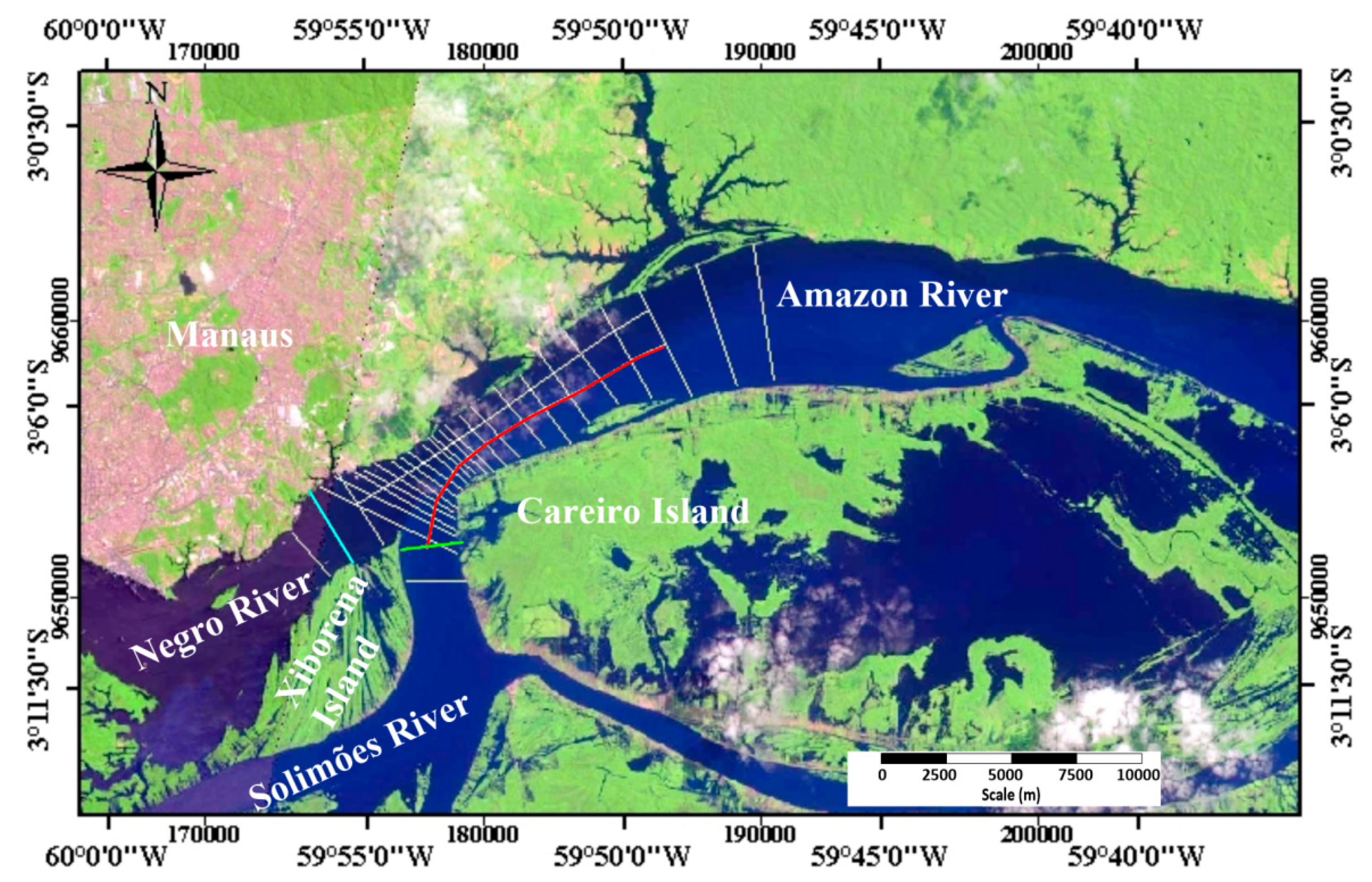
The study area is centered about the confluence of the Negro and Solimões Rivers, located near Manaus in Northern Brazil, where these rivers merge to form the Amazon River, (Figure 1). The Negro and Solimões confluence ranks among the largest on Earth and is famous for visibly revealing the meeting of the black (Negro) and white (Solimões) waters of the two rivers.
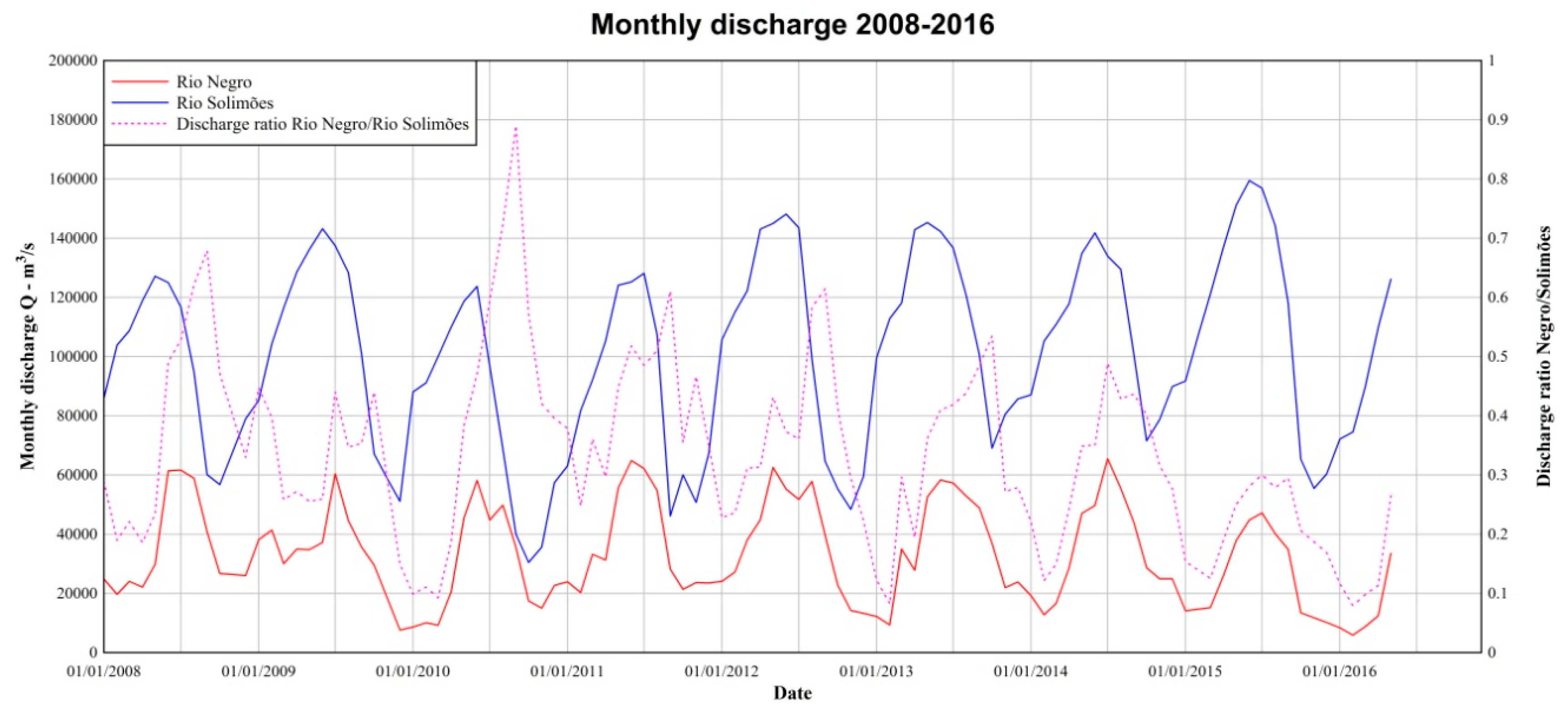
The distinct waters of these two rivers are related to the geology (soils, soil coverage, etc.) of the two respective catchments within the Amazon Basin. The Negro sub-basin is located in the North draining the western slopes of the Guyana Shield, which is characterised by gentle gradients and densely vegetated margin, which, in turn, implies a low sediment production [34], while the Solimões catchment includes the eastern margin of the Andes, where the combination of high declivity and erodible rocks gives origin to high sediment production [35,36]. The mean water discharge of the Negro and Solimões Rivers is about 30,000 and 100,000 m3/s, accounting for 14% and 49%, respectively, of the total freshwater discharge of the Amazon River into the Atlantic Ocean [34]. The two rivers have a different hydrological cycle: the Negro has two distinct discharge peaks along the year, the first of low-amplitude during the first three months of the year, and the second larger in the middle of the year; the Solimões has one peak between May and June [34]. Hydrologic data collected at the fluviometric stations, located in Tatu-Paricatuba (Negro River) and Manacapuru (Solimões River) (Figure 2), (www.ore-hybam.org/) show that low-flow conditions are occurring during the local Autumn, while the high-flow conditions occur during the local Winter season (June–July) (Figure 3). In terms of sediment load, the difference between the two rivers is even larger. The Solimões River has at the Manacapuru station an average load of suspended solids of 14,174 Kg/s, accounting for more than half of the total load of the Amazon River into the Atlantic Ocean, while the Negro River has at Paricatuba station an average suspended load of 254 Kg/s [37].

2.2. Field Campaigns

The field campaigns were carried out about the Negro/Solimões confluence in the Amazon River basin within the EU-funded Clim-Amazon Project, to study low flow (October 2014, FS−CNS1 campaign) and relatively high flow (April/May 2015, FS−CNS2 campaign) conditions [38,39,40,41,42,43]. The discharges measured during the campaigns were within the typical observed values for the seasons and daily differences were at most 5%. The surveys were carried out using an Acoustic Doppler Current Profiler (ADCP) as well as a multi-parameter probe for the measurement of water physico-chemical parameters (temperature, conductivity, turbidity, etc.) and total suspended sediment (TSS) concentration. During the surveys, a Teledyne RDI 600 kHz Rio Grande ADCP was used to collect flow velocity, water column backscattering [44] and water depth at key locations about the confluence. In total, 98 cross-sectional transects were collected. In addition, 2 and 3 longitudinal profiles along both sides of the Amazon River were collected in FS−CNS1 and FS−CNS2 surveys, respectively.

2.3. Basic Observations of Hydrodynamics and Morphodynamics about the Confluence

Table 2 lists the main flow properties of the Negro and Solimões rivers measured just upstream of the confluence (N-CNS and S-CNS, three for each river and each field campaign) during the two surveys. Large differences in discharge and flow velocities were observed in the Solimões River between the two surveys, whereas, on the Negro River, these differences were smaller.
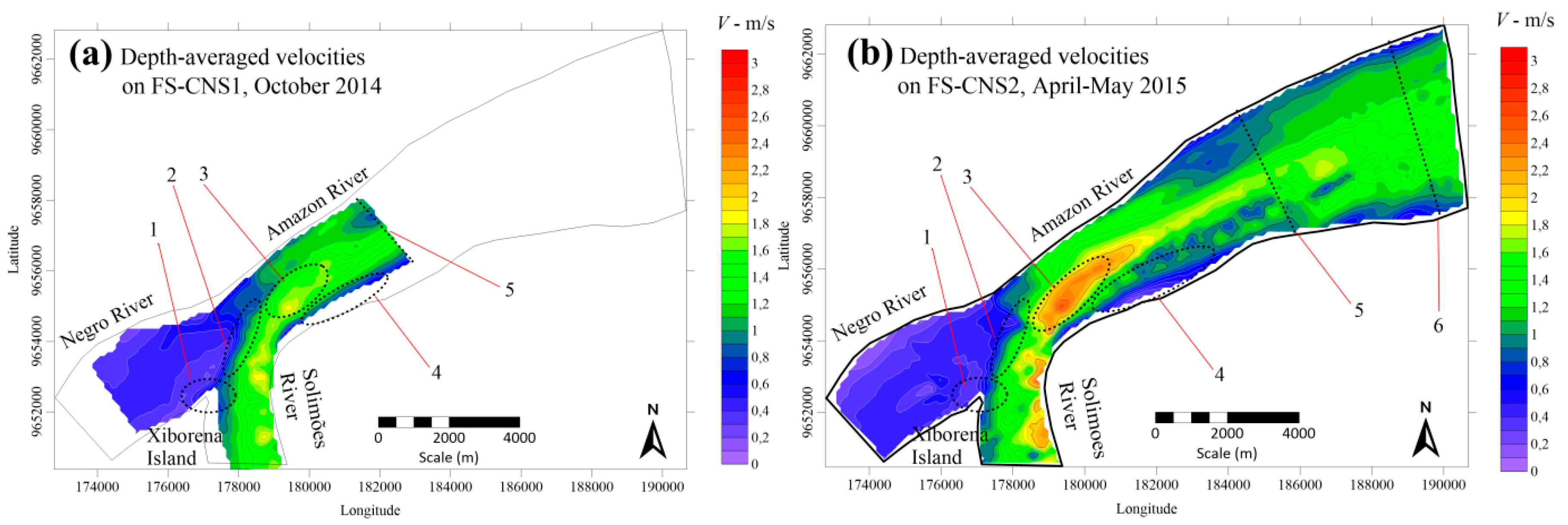
From FS−CNS1 to FS−CNS2, the maximum depth-averaged velocity was almost constant in the Negro River, but the Solimões River increased from 2.2 to 2.6 m/s. Furthermore, from low to high flow conditions, the Negro channel increased in depth, from 24 to 31 m, but not in width, whereas in the Solimões River the width increased from 1.6 to 1.9 km and the depth from 27 to 28 m. Finally, from FS−CNS1 to FS−CNS2, the median flow direction in the Negro River remained unchanged, whereas in the Solimões River a significant change in direction occurred. It is worth noting that the confluence junction angle is of about 65° (Figure 1). At the confluence entrance, the Negro channel is almost aligned with the Amazon channel, while the Solimões-Amazon waters must undergo a large change in flow direction (60°–70°) to enter in the Amazon channel. Common hydrodynamic features [32] already noted in past confluence studies were present even about the Negro/Solimões confluence. The approximate location of those features is shown in Figure 4, where they are numbered as: (1) the stagnation zone; (2) the region of deflection; (3) the region of maximum velocity; (4) the downstream separation zone; (5) the beginning of the region of flow recovery; and (6) the end of the CHZ. Further details about hydrodynamics are described in [41].
Ianniruberto et al. [43] identified that: upstream of the confluence, the Negro side is mostly characterized by a rocky bed with fine sand cover, whilst on the Solimões side the river bed consists predominantly of sand, and a sediment deposition region occurs at the junction corner in correspondence with the stagnation zone (Figure 4, feature 1); the central part of the CHZ is characterised by a sediment by-pass region exposing eroded Cretaceous bedrock, with a scour hole corresponding to the region of maximum velocity (Figure 4, feature 3); deposited sediment forming a bank-attached bar on the Solimões side of the CHZ (Figure 4, feature 4); avalanche faces of sediments at the Solimoes mouth; a bedrock terrace was observed towards the downstream end of the CHZ (Figure 4, feature 5), marking the transition from rocky to alluvial bed, where the bedforms were found.

3. Bedforms morphology. Results and Discussion

3.1. Hydrodynamics and Sediment Transport Parameters along the Longitudinal Transects. Results

The location and length of the two longitudinal transects collected in the area of the confluence during FS−CNS1 and FS−CNS2, approximately 900 m away from the Solimões/Amazon right bank, are presented in Table 3 and Figure 1.
The ADCP measurements provided data about water depth and velocity. The observed water depth ranged from 21 to 68 m, with an increase of about 6–7 m from low to relatively high flow conditions. Table 4 lists the minimum, average, median and maximum value of the depth-averaged velocity along the ADCP transects as well as its standard deviation. No large variations were observed from low flow to relatively high flow conditions on minimum and average velocity, but the maximum depth-averaged velocity increased from 2.2 to 2.8 m/s. Figure 5 and Figure 6 show the longitudinal distribution of the depth-averaged velocity in the ADCP transects collected in FS−CNS1 and FS−CNS2, respectively.
Downstream from the mouth of the Solimões, the longitudinal transect was initially located on the rocky scour hole, with a depth larger than 60 m. After the scour hole, it was observed a wide sandstone terrace at depth of about 35 m, gently sloping downstream, followed by sharp 30 m decrease in depth. Downstream of this large depression, the bedforms were found [43]. The starting point of the bedforms is located within the flow recovery region, where the Amazon channel is widening, at approximately 4.7 km downstream of the confluence junction. Interestingly, the bedform size seems to increase and the shape changes with downstream distance.
Some parameters related to sediment transport were calculated. In alluvial channels, friction is related both to the grain resistance and to the form of bedform and the total shear stress is [2,45]:
τ b = τ b + τ b
where τ′b and τ″b are the skin friction shear stress and the form-related shear stress, respectively.
The skin friction shear stress was calculated as [46]:
τ b = ρ C d V d e p t h a v g 2
where Cd is the drag coefficient, which was obtained as:
C d = κ 2 ln 2 ( h / e   z 0 )
where κ is the von Kármán constant, e is the Euler number and z0 is the zero−velocity height above the bed, which can be obtained as [47]:
z 0 = 0.1   d 84
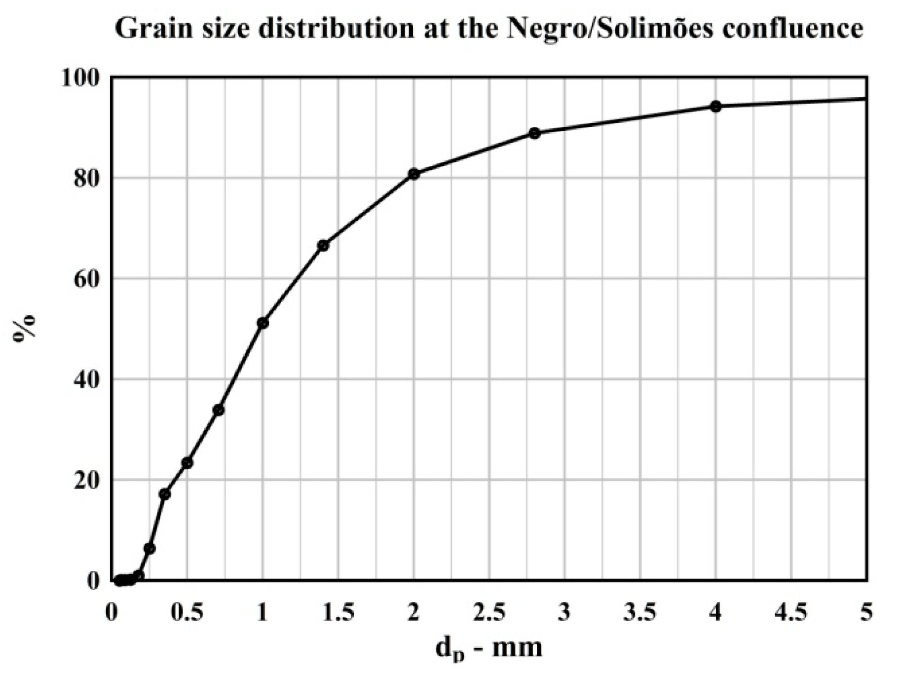
where d84 is bed grain diameter such that 84% of diameters are finer (Figure 7) [48]. The water density was calculated from the temperature T as:
ρ = −0.0054 T2 + 0.021 T + 1000 (kg/m3)
The form-related shear stress was computed as [2]:
τ b = 1 2 ρ V d e p t h a v g 2 H b f 2 L b f h
where Hbf and Lbf are bedforms height and length, respectively, and h is water depth.
Table 5 lists the minimum, average, standard deviation, median and maximum value of the bed shear stress along the ADCP transects calculated using Equation (1). No large variations were observed in the median value from low to relatively high flow conditions. Finally, the shear stress allows us to calculate the maximum suspended grain size dss [49]:
d s s = 18 ρ ν · 0.8 · τ b / ρ g ( ρ s     ρ )   ( m )
where ρs is the particle density, and ν is the water kinematic viscosity, that was calculated as:
ν = (5.85 10−10 ∗ T2) − (4.85 10−8 ∗ T + 1.74 10−6) (m2/s)
Table 6 lists the minimum, average, standard deviation, median and maximum value of the maximum suspended grain size along the ADCP transects calculated using Equation (7). The maximum suspended grain sizes were generally in the order of fine sand (0.125−0.250 mm) with a highest value in the range of medium sand (0.250−0.500 mm) in both flow conditions.

3.2. Bedform Morphology. Results and Discussion

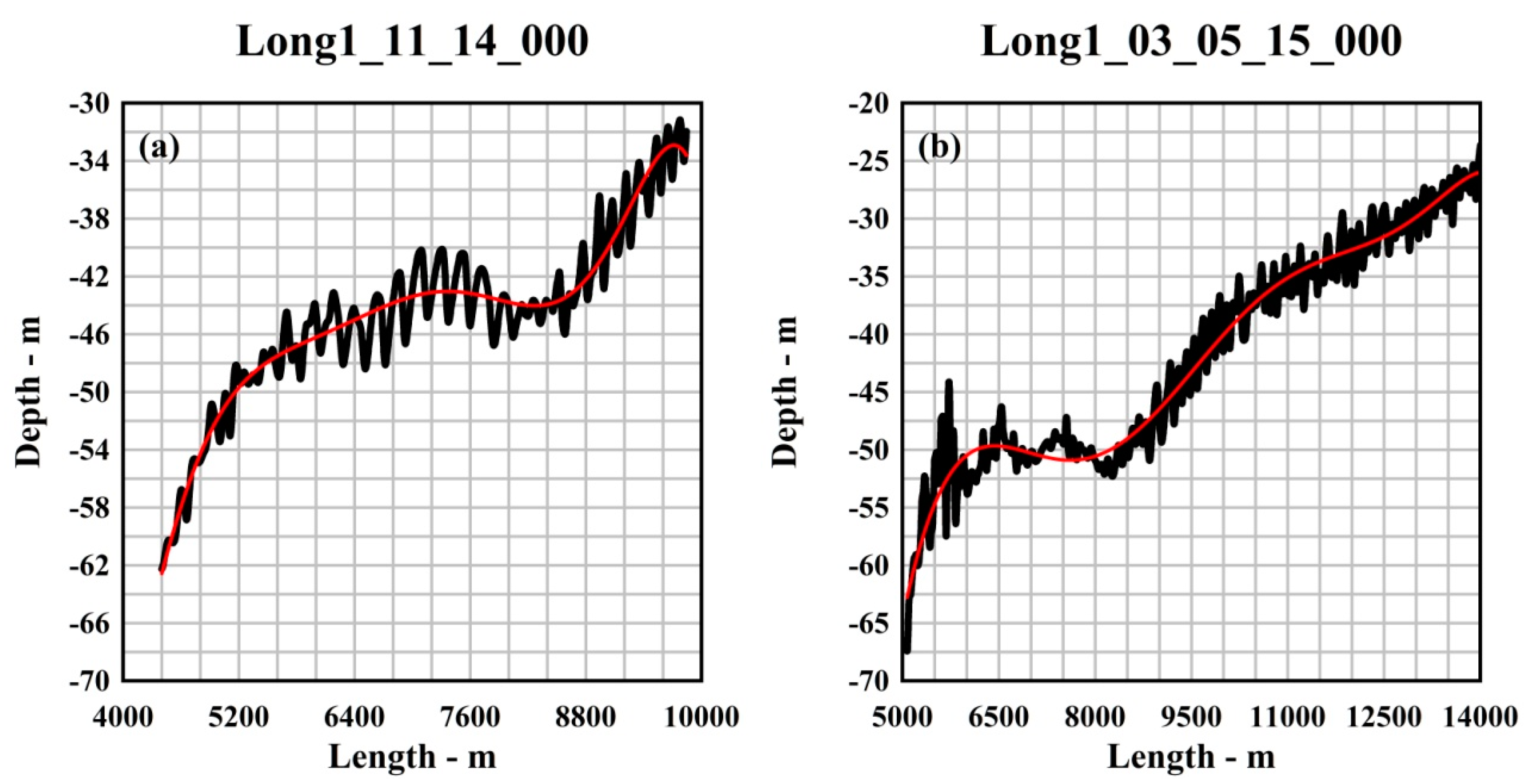
Bedform characteristics were derived through several steps. The raw ADCP data were first extracted with WinRiver II. Then, the ADCP data were processed to get depth-averaged vertical and streamwise velocities according to the procedure described in Bahmanpouri et al. [50] with the addition of a further low-pass filtering to remove spikes and noise. The next stage was to track the bottom profile to detect the bedforms as anomaly relative to a reference depth. To this aim, a Matlab code was implemented: a seventh-grade polynomial fit curve was chosen (Figure 8) to define a reference depth used to detect using visual analysis individual bedforms as a succession of trough–crest–trough and to estimate their wavelength and wave height. Using this procedure, further metrics such as wave steepness, lee side and stoss side lengths and angles were calculated.
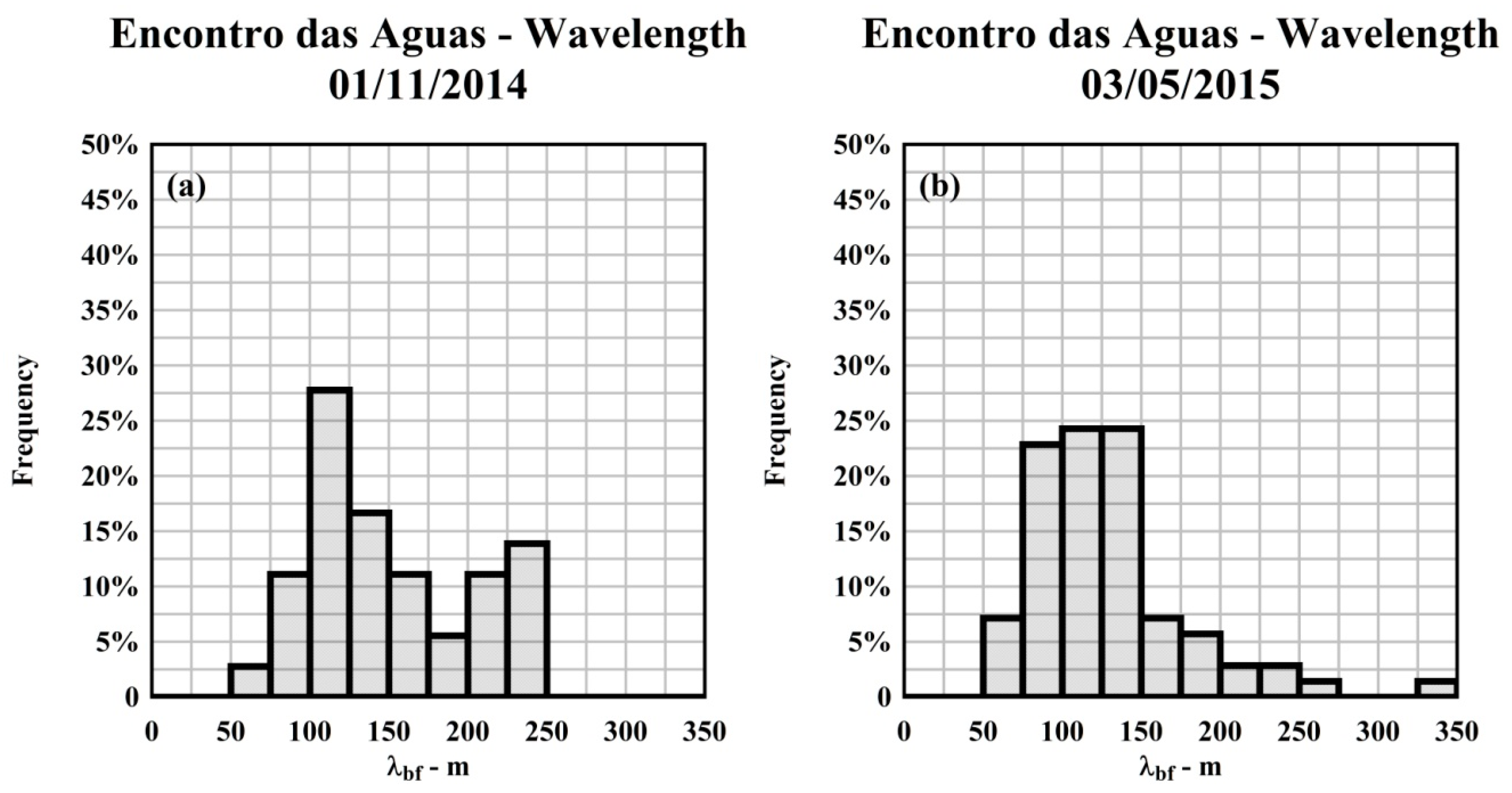
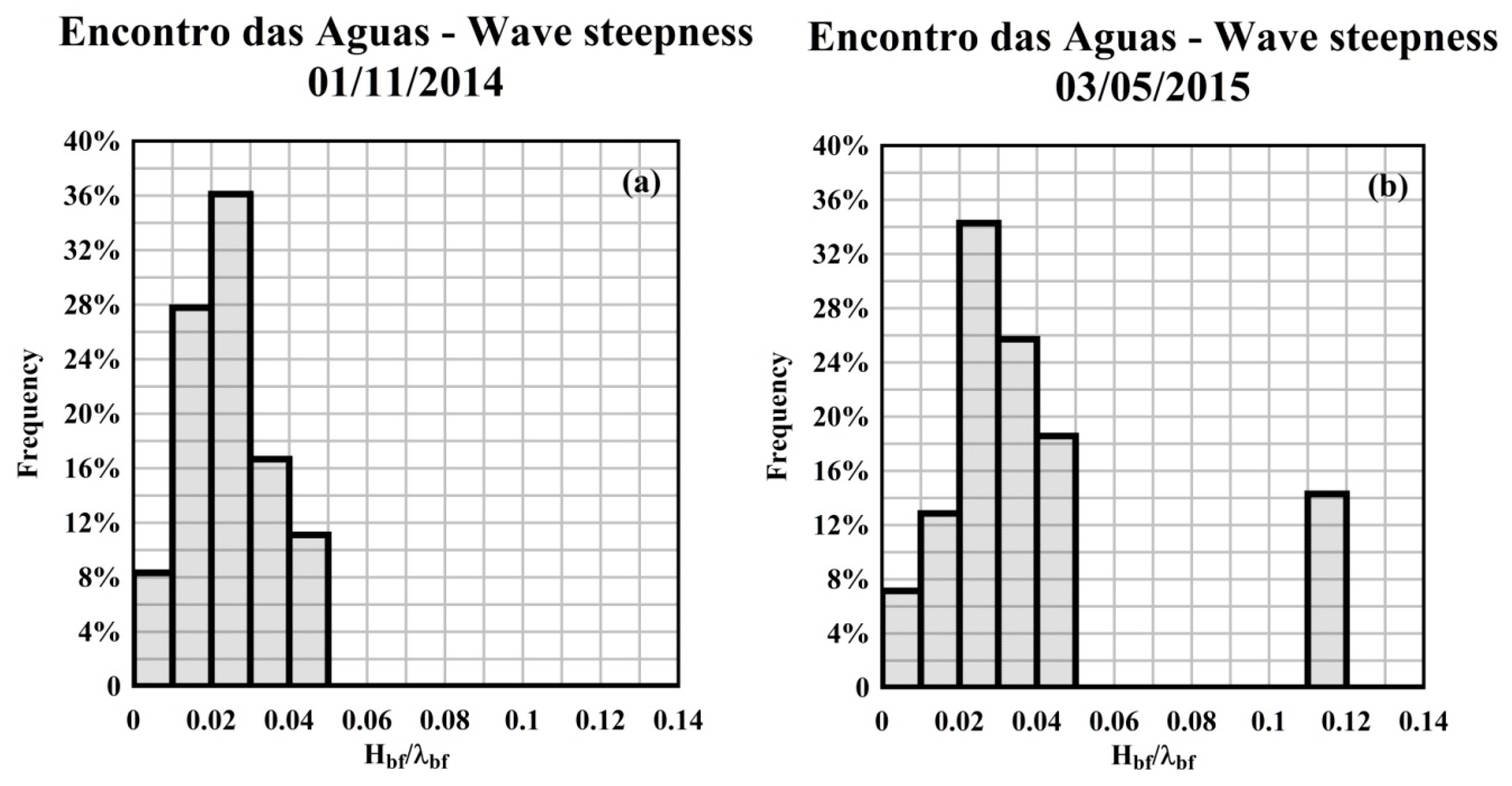
Table 7, Table 8 and Table 9 list the minimum, average, median and maximum value of the wavelength λbf, wave height Hbf and wave steepness Hbf/λbf as well as their standard deviation for the bedforms observed during this study. The datasets for FS−CNS1 and FS−CNS2 were termed “Encontro das Aguas—1 November 2014” and “Encontro das Aguas—3 May 2015”, respectively. Figure 9, Figure 10 and Figure 11 show the frequency distribution for these parameters. For each parameter 14 classes in size were considered. The 2D analysis identified 36 and 70 bedforms, which were all classified from Table 1 [22] at least as large dunes (λbf > 10 m), while very large dunes (λbf > 100 m) were 86% and 70%, in FS−CNS1 and FS−CNS2, respectively. The minimum wavelength λbf was equal to 55 m, observed in the FS−CNS2. The maximum wavelength was found in relatively high flow conditions and it was longer than 330 m. On average, the wavelength λbf was 150 and 128 m for FS−CNS1 and FS−CNS2, respectively, while the average wave height Hbf was 3.7 m in both cases. The average steepness Hbf/λbf was of 2.5% and 3.0% for FS−CNS1 and FS−CNS2, respectively. The distribution of the wavelength of the observed bedforms had a small percentage (14% and 30%) of bedforms shorter than 100 m.
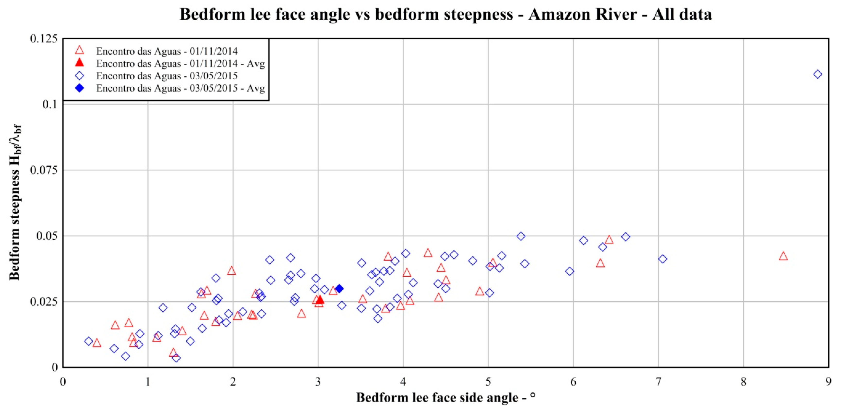
The lee side angle was constantly below 10°, with a maximum value of 8.47° and 8.87° and an average value of 3.02° and 3.25°, in FS−CNS1 and FS−CNS2, respectively. These values are generally consistent with those from large rivers where low-angle (<10°) lee-side slopes are predominant [15]. The asymmetry, defined as the ratio of stoss side length to the bedform length, was on average 0.56 and 0.47 in FS−CNS1 and FS−CNS2, respectively.
In the rising stage from October 2014 (FS−CNS1) to April/May 2015 (FS−CNS2), on average, the wavelength decreased, the steepness increased and the wave height remained unchanged, while the maximum sizes increased. Furthermore, a comparison between the frequency distribution of bedform size in low and relatively high flow conditions showed an increase in wavelength and wave height as the river discharge increased, in agreement with the past literature studies (Figure 9, Figure 10 and Figure 11). However, as the two ADCP transects are different in length of about 4 km and have a different number of bedforms, the comparison was repeated considering only the bedforms located on the same reach of the two longitudinal transects. The results confirmed the above findings. At the end, the bedforms observed in this study were generally characterised by large wavelengths, ranging from 55 to 335 m, with a median value of 133 and 120 m, respectively, and wave height on average larger than 3 m. The wave steepness was in the range from 0.3% to 11%.

3.3. Modeling Bedforms Morphology. A Comparison with Predictive Equations. Discussion

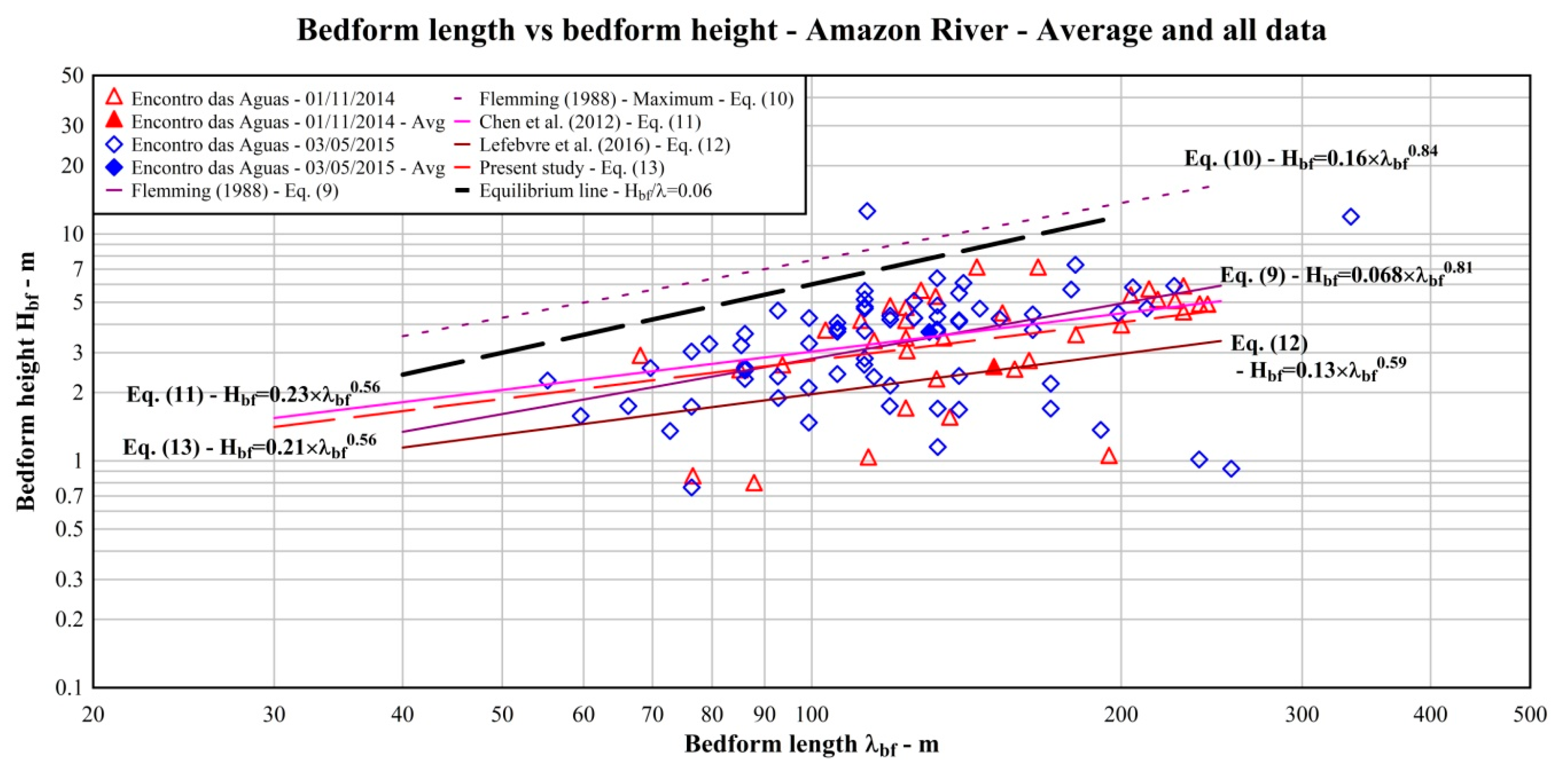
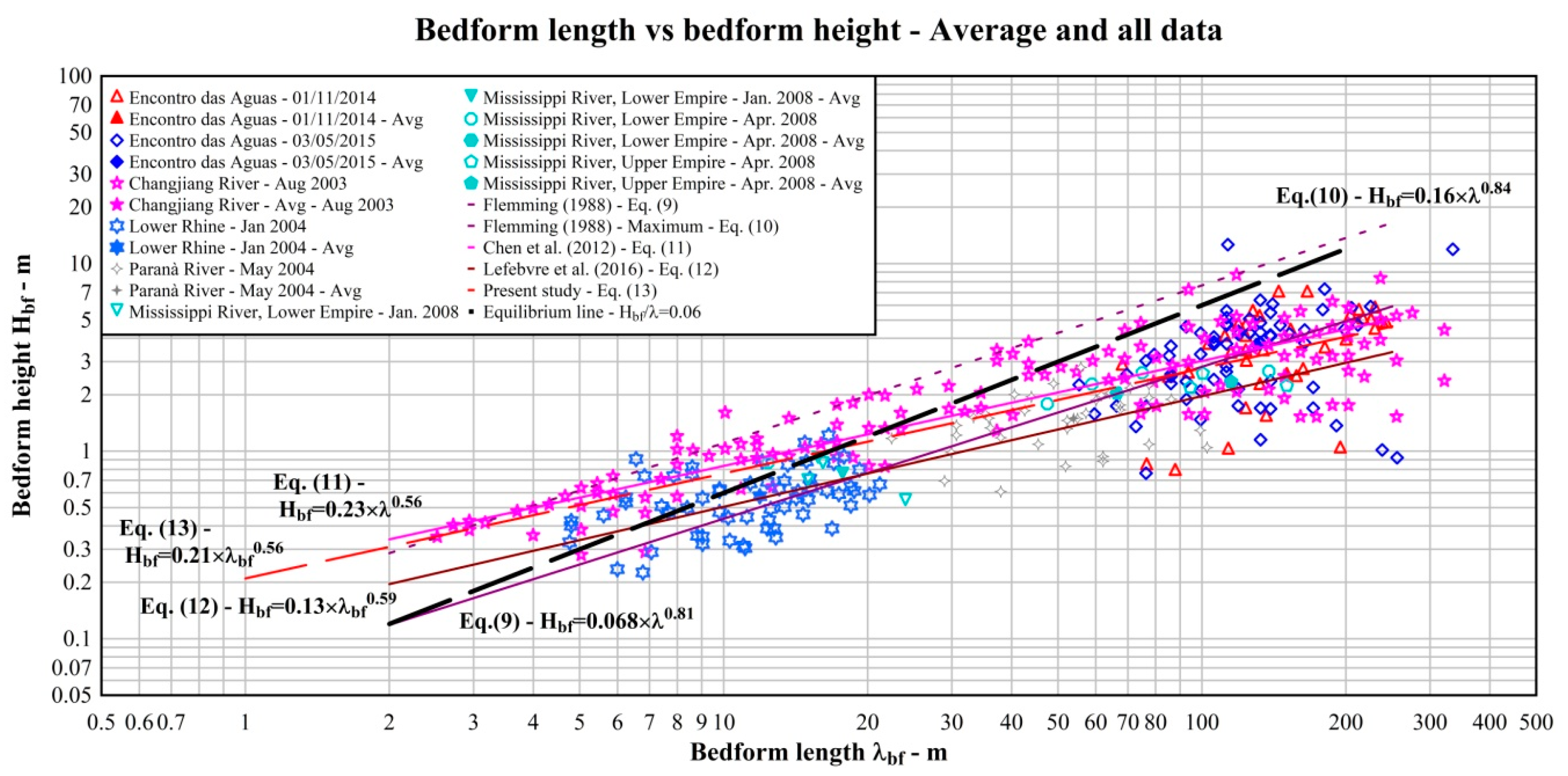
As already pointed out, dune development is related to both their deformation during migration and their adaptation to flow variations [9]. Dune adaptation has been extensively investigated as an important process in river morphodynamics, but there is not yet a universal model to predict changes in dune sizes in response to flow variations. This morphological response has been often related to sediment mobility, which itself is a product of flow depth and velocity [9], and dune size has been related to flow depth as a result of interaction between large eddies in the flow and the sediment bed [17,51,52], Bedform wavelength was plotted versus bedform wave height [13,20,26,53] and the data were compared with the empirical relationships proposed by Flemming, which were based on 1491 deep sea, tidal and river bedforms [22]:
H b f = 0.068   λ b f 0.81   ( m )
H b f - m a x = 0.16   λ b f 0.84   ( m )
where Equation (9) represents a range of steepness Hbf/λbf from 0.08 to 0.1 [20]. Figure 12 shows the results for the bedforms observed in the field surveys, including their respective averages. The data were also compared with the equation proposed by Chen et al. [13] using experimental data collected in the middle–lower Changjiang (Yangtze) River (China):
H b f = 0.23   λ b f 0.56   ( m )
Furthermore, the equation proposed by Lefebvre et al. [53], who used the data from the Rio Paranà (Argentina) [12] and those from the Lower Rhine (the Netherlands) [54], was included:
H b f = 0.13   λ b f 0.59   ( m )
Using the data from the two field surveys, it was possible to derive a new regression equation:
H b f = 0.21   λ b f 0.56   [ m ]
which is very close to Equation (11). Furthermore, theory and laboratory studies in uniform and steady flow suggest that dunes with a steepness Hbf/λbf less than 0.06 are either non-equilibrium bedforms or represent an equilibrium adjustment of the bed form, in which maximum steepness is precluded by hydraulic constraints, notably a depth limitation [20]. The equilibrium line corresponding to Hbf/λbf = 0.06 was also included in Figure 12. All the bedforms, but one, were below Flemming’s maximum line (Equation (10)). Only some of large dunes (10.0 > λbf > 100 m) were well aligned between Equation (11) and Equation (9) and close to the equilibrium line, while in many cases they showed a large scatter from these lines. On the other hand, most of the very large dunes (λbf > 100 m) were well aligned with both Chen et al. [13] (Equation (11)) and Flemming’s (Equation (9)) lines and close to the equilibrium line, but several bedforms from FS−CNS2 and also a number from FS−CNS1 had a low wave height, corresponding to a steepness in the order of 0.01–0.02, so they may represent bedforms in adaptation. It is worth noting that during FS-CNS1, the longitudinal transect was collected after seven days of near-constant low-flow discharges, while FS-CNS2 was conducted during a period of continuously rising flow discharges. This could explain why the dune field may have mostly obtained a stable equilibrium with the flow conditions during FS-CNS1, while dune field was in a transitional phase during FS-CNS2 as it adjusted to the increasing flow discharge.
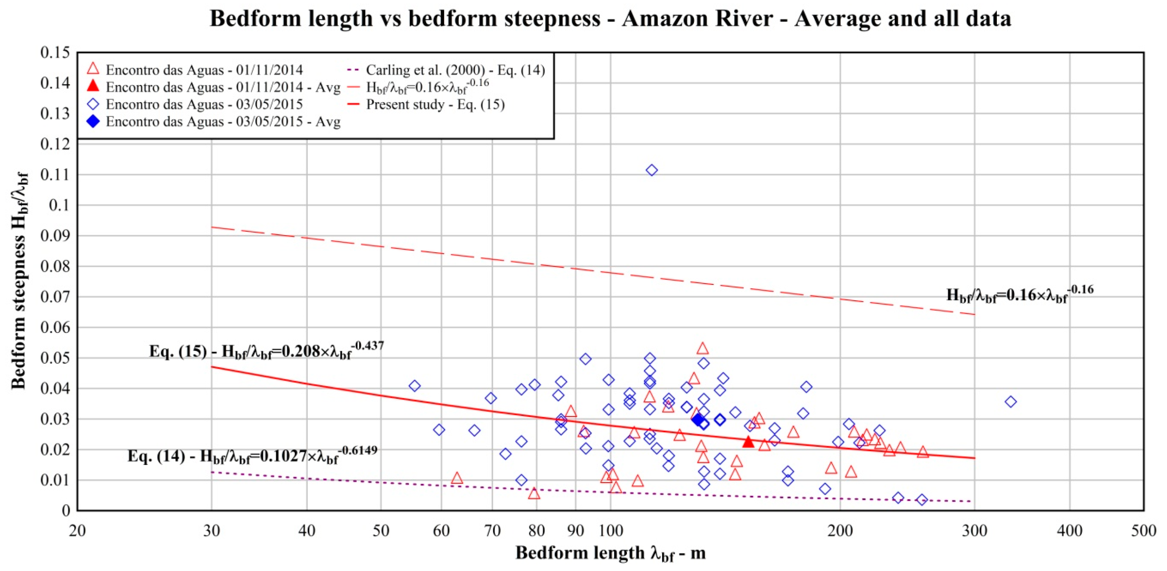
The length of the bedforms observed in the three field surveys were plotted against their steepness Hbf/λbf in Figure 13 and compared with the relationship proposed by Carling et al. [20]:
H b f λ b f = 0.1027   λ b f 0.615   ( - )
and a new regression equation was derived:
H b f λ b f = 0.208   λ b f 0.437   ( - )
Several bedforms, in both flow conditions, were characterised from steepness in the order of 0.01–0.2. This indicates that the bedforms with low steepness observed in FS−CNS2 were developing with the increasing discharge, while, on the other side, those in FS−CNS1 were in the process of crest flattening and elongation, having been formed during the previous high flow conditions [13].
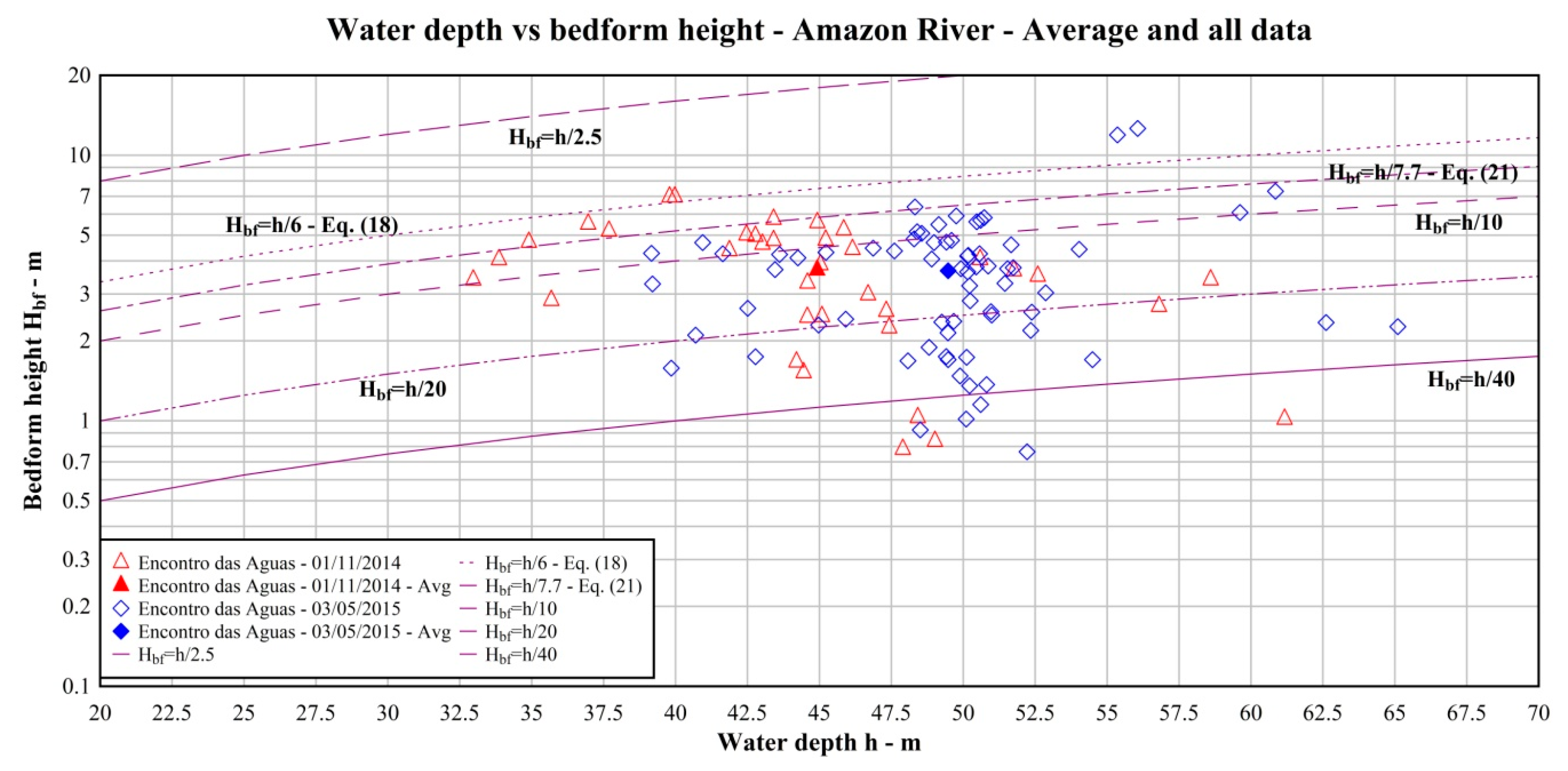
As already mentioned above, dune sizes are often thought to scale with flow depth [10,11,17,26,51,52,55], as developing dunes cannot emerge out of the water [26], but, in the literature, other scaling relationships based on depth and grain size [24], transport stage [23,56] and transport stage and Froude number [57] were proposed. Transport stage is generally defined as any metric that is composed of a ratio of the shear stress to a grain size [25,26], including the Shields number and the Rouse number, which is defined as:
R o = w s κ   u *  
where ws is particle settling velocity and u* is the shear velocity, which can be obtained from the total bed shear stress τb as u* = (τb/ρ)0.5. The most widely applied scaling equation for dune size is that of Yalin [51], where bedform wavelength and wave height are related to the flow depth as:
λ b f = 5   h   ( m )
H b f = h 6   ( m )
while Yalin [52] suggested a theoretical value of λbf = 5 h for equilibrium dunes in deep flows. Venditti [55] analyzed Allen’s [58] dataset and identified a range of variability between h and 16 h for bedform length and between 1/40 h and 1/6 h for the bedform height. He also argued that the reason for this variability is that bedform sizes are dependent on transport stage and lag changes in the flow conditions.
Bradley and Venditti [26] re-evaluated seven predictive equations, including those from Yalin, linking dune dimensions to other variables such as flow depth, grain size, transport stage and Froude number. The data compilation using 498 observations coming from 21 flume experiments and 20 field studies shows that dune height and length follow a power law:
H b f = 0.051   λ b f 0.77   ( m )
which is very similar to Flemming’s equation (Equation (9)). Most of the data for bedform length and height were ranging from h to 16 h and from h/20 to h/2.5, respectively. Bradley and Venditti [26] found that the predictive power of all the scaling relations was generally poor probably because these relations are not able to capture any effect of the flow variability over the time. They also observed that dunes in smaller channels conform to a different height scaling than dunes in larger channels, which reflects a change in dune morphology from strongly asymmetric dunes with high lee angles in flows <2.5 m deep to more symmetric, lower lee angle dunes in flows >2.5 m deep [26]. This implies a different process control rather than a continuum of processes as depth increases [26]. Hence, from the analysis of only data in channels with depth h > 2.5 m, they derived two different equations for wave height, a linear regression equation and a non-parametric scaling equation:
H b f = 0.13   h 0.94   ( m )
H b f = h 7.7   ( m )
while, for all the data, they derived for wavelength again a linear regression equation and a non-parametric scaling equation:
λ b f = 5.22   h 0.95   ( m )
λ b f = 5.9   h   ( m )
Bradley and Venditti [26] recommended to apply non-parametric scaling relations, i.e., Equations (21) and (23), concluding that if it is clear that dunes increase its sizes with the scale of the river system, a sound explanation for how flow depth rules the equilibrium sizes of dunes is still lacking. Rather, the apparent scaling of dunes with flow depth may be only indirect and emerge because shear stress/velocity, both depending on depth, play a key role in dune morphology [26].
Figure 14 and Figure 15 present the relationship between water depth and bedform wavelength and wave height, respectively, for the dunes observed in this study. The data were not exceeding the upper limits of scaling reported by [55]. On the other hand, while length data were quite well aligned between the curves for λbf = 5.9 h (Equation (23)) and λbf = h (Figure 14), height data ranged mostly from Hbf = h/6 to Hbf = h/40, with some values above and below these curves (Figure 15). The bedforms with low wave height, i.e., Hbf < h/20 or Hbf < h/40, observed mostly in FS−CNS2 were probably adapting to the raising stage to high flow conditions. Finally, most of the wave height data were below the curve for h/10, confirming the findings observed in large rivers where height is often only 10% of the local flow depth [15].
Bedform sizes were also related to the transport stage expressed by the suspension number u*/ws [25], which is the inverse of the Rouse number (Equation (15)) multiplied by the von Kármán constant. Figure 16 presents the distribution of the relative bedform wavelength λbf/h and wave height Hbf/h against the suspension number u*/ws, being in both flow conditions, in the range from 0.3 to 0.6. The lee side angle was below 10°, with an average value of 3.02° and 3.25° in 2014 and 2015 surveys, respectively. Lee side angles showed an interesting relationship to wave steepness (Figure 17). Bedform steepness grew gently with lee side angle and became constant above 6° at Hbf/λbf = 0.05, suggesting an interrelation between these parameters in this case [53]. Finally, the analysis of vertical velocity measured in the ADCP transects showed no flow separation due to the low lee side angles, as reported in past studies on low-angle dunes [1,15,59].

3.4. Comparison with Literature Data Sets from Large Rivers. Discussion

The field data collected is this study were compared with those from some literature data sets collected in large rivers. These data sets are: the side-scan sonar and sub-bottom profiler data collected in August 2003 in the middle–lower Changjiang (Yangtze) River (China) [13], and the multibeam echosounder data collected in January 2004 in the Lower Rhine (The Netherlands) [54], in May 2004 in the Rio Paraná (Argentina) [12], and in April 2008 in the Empire Reach of the lowermost Mississippi River (USA) [60]. Table 10 lists the main size parameters for these data sets.
Figure 18 presents the relationship between bedform wavelength and bedform wave height for the dunes observed in the present study and those reported in the above literature data sets along with the empirical regression laws in Equations (9)–(13). In the range of medium dunes (5.0 > λbf > 10 m) or more, the data from the Lower Rhine and Mississippi River were aligned with Equation (9), while the data from the Changjiang River were proximal to Flemming’s maximum line (Equation (10)) and their steepness was larger than 0.06. Moreover, several data from the Lower Rhine were below Flemming’s line (Equation (9)). In the range of large dunes (10.0 > λbf > 100 m), most of the dunes from Rio Paraná and several from the Changjiang River were aligned with Equation (13) and close to the equilibrium line, but a number of dunes from Rio Paraná were below Flemming’s line (Equation (9)). In the range of very large dunes (λbf > 100 m), most of the literature data were close to the Amazon River data and it is possible to observe that a number of data from the Changjiang River were characterised from low wave height and steepness in the order of 0.01, as they were probably adapting to changes in flow conditions.

4. Conclusions

In alluvial rivers, the geometry of the bed topography is the result of a complex interaction among several hydrodynamics and sedimentary processes acting under the constraint of varying boundary conditions. In sand-bedded alluvial channels, the bottom boundary consists of a labile bed comprising bedforms of many different scales and geometries. Bedforms are deformations of a sand bed that are smaller than channel-scale bar forms and that have specific geometric properties [26,55]. They also are subjected to deformation and adaptation to changes in river flow [9]. This paper presented the results of a study about the morphology of the bedforms observed in the area of the Negro/Solimões confluence. Two surveys using acoustic Doppler velocity profiling (ADCP) were carried out in low flow (FS-CNS1) conditions, after seven days of near-constant discharge, and in relatively high flow (FS-CN2) conditions, during a period of continuously rising flow discharges. The observed bedforms were mostly in the range of large and very large dunes according to Ashley [22] classification with a maximum wavelength and wave height of 350 and 12 m, respectively. Second, during (FS-CN2), maximum bedform sizes as well as in the frequency distribution of bedform size were comparatively larger, as could be expected from the literature studies. Third, most of the large dunes (10.0 > λbf > 100 m) and very large dunes (λbf > 100 m) were generally in equilibrium with flow conditions. On the other side, some bedforms observed in relatively high flow conditions were developing to adjust to the continuously increasing flow discharge, while only some in low flow conditions were in the process of crest flattening and elongation, having been formed during the previous high flow conditions. Fourth, the data were within the upper limits of scaling with water depth reported in the literature, but, while length data were quite well aligned with scaling curves, height data showed a scatter from these curves. Fifth, in both surveys, the lee side angle was below 10° with an average value of about 3.0° and no flow separation was observed confirming recent literature studies on large rivers [15], and wave steepness grew gently with lee side angle and became constant above 6° at Hbf/λbf = 0.05. Finally, a comparison between the data collected in this study and past literature studies on large rivers suggested that a number of the largest bedforms were probably adapting to discharge variations in the river.

Author Contributions

All the authors contributed to this study. Analysis and investigation, C.G., I.M., N.P.F.J. and M.I.; data processing, C.G. and I.M.; writing—original draft preparation, C.G.; writing—review and editing, I.M., N.P.F.J. and M.I.; visualization, C.G., I.M. and M.I.; funding acquisition, C.G., N.P.F.J. and M.I. All authors have read and agreed to the published version of the manuscript.

Funding

This research was carried out within the Clim-Amazon Research Project funded by grant agreement FP7 INCO-LAB n°295091 from the European Commission. Naziano Filizola acknowledges funding by CAPES-Procad Amazonia and CNPq-AmazonGeoSed Project.

Acknowledgments

The authors acknowledge Mark Trevethan for his valuable collaboration in the Clim-Amazon Project and the CPRM (Geological Survey of Brasil) for supplying the research vessel, instrumentation, technical assistance with sampling; Bosco Alfenas, Andrè Martinelli Santos, Daniel Moreira, Arthur Pinheiro, Paulo Melo, Nilda Pantoja, Andre Zumak and João Andrade for their assistance with sampling during the surveys; and finally Farhad Bahmanpouri for his assistance in the extraction of the ADCP data.

Conflicts of Interest

The authors declare no conflict of interest.

References

  1. Best, J.L. The fluid dynamics of river dunes: A review and some future research directions. J. Geophys. 2005, 110, F04S02. [Google Scholar] [CrossRef]
  2. Chanson, H. The Hydraulics of Open Channel Flow: An Introduction, 2nd ed.; Butterworth-Heinemann: Oxford, UK, 2004; p. 630. [Google Scholar]
  3. Andreotti, B.; Claudin, P.; Devauchelle, O.; Duràn, O.; Fourrière, A. Bedforms in a turbulent stream: Ripples, chevrons and antidunes. J. Fluid Mech. 2012, 690, 94–128. [Google Scholar] [CrossRef] [Green Version]
  4. Stoesser, T.; Braun, C.; Garcìa-Villalba, M.; Rodi, W. Turbulence Structures in Flow over Two-Dimensional Dunes. J. Hydraul. Eng. 2008, 134, 42–55. [Google Scholar] [CrossRef]
  5. Omidyeganeh, M.; Piomelli, U. Large-eddy simulation of three-dimensional dunes in a steady, unidirectional flow. Part 1. Turbulence statistics. J. Fluid Mech. 2013, 721, 454–483. [Google Scholar] [CrossRef] [Green Version]
  6. Omidyeganeh, M.; Piomelli, U. Large-eddy simulation of three-dimensional dunes in a steady, unidirectional flow. Part 2. Flow structures. J. Fluid Mech. 2013, 734, 509–534. [Google Scholar] [CrossRef] [Green Version]
  7. Bennett, S.J.; Best, J.L. Mean flow and turbulence structure over fixed, two dimensional dunes: Implications for sediment transport and bedform stability. Sedimentology 1995, 42, 491–513. [Google Scholar] [CrossRef]
  8. Ojha Satya, P.; Mazumder, B.S. Turbulence characteristics of flow over a series of 2-D bed forms in the presence of surface waves. J. Geophys. Res. Earth Surf. 2010, 115, F404016. [Google Scholar]
  9. Reesink, A.J.H.; Parsons, D.R.; Ashworth, P.J.; Best, J.L.; Hardy, R.J.; Murphy, B.J.; McLelland, S.J.; Unsworth, C. The adaptation of dunes to changes in river flow. Earth-Sci. Rev. 2018, 185, 1065–1087. [Google Scholar] [CrossRef] [Green Version]
  10. Bradley, R.W.; Venditti, J.G. Transport scaling of dune dimensions in shallow flows. J. Geophys. Res. Earth Surf. 2019, 124, 526–547. [Google Scholar] [CrossRef]
  11. Bradley, R.W.; Venditti, J.G. The growth of dunes in rivers. J. Geophys. Res. Earth Surf. 2019, 124, 548–566. [Google Scholar] [CrossRef]
  12. Parsons, D.R.; Best, J.L.; Orfeo, O.; Hardy, R.J.; Kostaschuk, R.; Lane, S.N. Morphology and flow fields of three-dimensional dunes, Rio Paranà, Argentina: Results from simultaneous multibeam echo sounding and acoustic Doppler current profiling. J. Geophys. Res. Earth Surf. 2005, 110, F04S03. [Google Scholar] [CrossRef] [Green Version]
  13. Chen, J.; Wang, Z.; Li, M.; Wei, T.; Chen, Z. Bedform characteristics during falling flood stage and morphodynamic interpretation of the middle-lower Changjiang (Yangtze) River channel, China. Geomorphology 2012, 147–148, 18–26. [Google Scholar] [CrossRef]
  14. Bialik, R.J.; Karpiński, M.; Rajwa, A.; Luks, B.; Rowiński, P.M. Bedform Characteristics in Natural and Regulated Channels: A Comparative Field Study on the Wilga River, Poland. Acta Geophys. 2014, 62, 1413–1434. [Google Scholar] [CrossRef]
  15. Cisneros, J.; Best, J.L.; van Dijk, T.; Paes de Almeida, R.; Amsler, M.; Boldt, J.; Freitas, B.; Galeazzi, C.; Huizinga, R.; Ianniruberto, M.; et al. Dunes in the world’s big rivers are characterized by low-angle lee-side slopes and a complex shape. Nat. Geosci. 2020, 13, 156–162. [Google Scholar]
  16. Julien, P.Y.; Klaassen, G.J.; Ten Brinke, W.B.M.; Wilbers, A.W.E. Case Study: Bed Resistance of Rhine River during 1998 Flood. J. Hydraul. Eng. 2002, 128, 1042–1050. [Google Scholar] [CrossRef] [Green Version]
  17. Cheel, R.J. Introduction to Clastic Sedimentology, Course Notes; Brock University: St. Catharines, ON, Canada, 2005. [Google Scholar]
  18. Almeida, R.P.; Galeazzi, C.P.; Freitas, B.T.; Janikian, L.; Ianniruberto, M.; Marconato, A. Large barchanoid dunes in the Amazon River and the rock record: Implications for interpreting large river systems. Earth Planet. Sci. Lett. 2016, 454, 92–102. [Google Scholar] [CrossRef]
  19. Simons, D.B.; Richardson, E.V. Resistance to Flow in Alluvial Channels; Technical Report for Geological Survey Professional Paper 422-J; United States Government Printing Office: Washington, DC, USA, 1961.
  20. Carling, P.A.; Gölz, E.; Orr, H.G.; Radecki-Pawlik, A. The morphodynamics of fluvial sand dunes in the River Rhine, near Mainz, Germany. I. Sedimentology and morphology. Sedimentology 2000, 47, 227–252. [Google Scholar] [CrossRef]
  21. Yalin, M.S. The Mechanics of Sediment Transport, 2nd ed.; Pergamon Press: Oxford, UK, 1977; p. 298. [Google Scholar]
  22. Ashley, G.M. Classification of large-scale subaqueous bedforms: A new look at an old problem. J. Sediment Res. 1990, 60, 160–172. [Google Scholar]
  23. Van Rijn, L.C. Sediment Transport, Part III: Bed forms and Alluvial Roughness. J. Hydraul. Eng. 1984, 110, 1733–1754. [Google Scholar] [CrossRef]
  24. Julien, P.Y.; Klaassen, G.J. Sand-dune geometry of large rivers during floods. J. Hydraul. Eng. 1995, 121, 657–663. [Google Scholar] [CrossRef]
  25. Naqshband, S.; Ribberink, J.S.; Hulscher, S.J. Using both free surface effect and sediment transport mode parameters in defining the morphology of river dunes and their evolution to upper stage plane beds. J. Hydraul. Eng. 2014, 140, 06014010. [Google Scholar] [CrossRef]
  26. Bradley, R.W.; Venditti, J.G. Reevaluating dune scaling relations. Earth-Sci. Rev. 2017, 165, 356–376. [Google Scholar] [CrossRef]
  27. Kostaschuk, R.; Best, J. Response of sand dunes to variations in tidal flow: Fraser Estuary, Canada. J. Geophys. Res. Earth Surf. 2005, 110, F04S04. [Google Scholar] [CrossRef] [Green Version]
  28. Maddux, T.B.; Nelson, J.M.; McLean, S.R. Turbulent flow over three-dimensional dunes: 1. Free surface and flow response. J. Geophys. Res. Earth Surf. 2003, 108, 6009. [Google Scholar] [CrossRef]
  29. Maddux, T.B.; Nelson, J.M.; McLean, S.R. Turbulent flow over three-dimensional dunes: 2. Free surface and flow response. J. Geophys. Res. Earth Surf. 2003, 108, 6010. [Google Scholar] [CrossRef]
  30. Best, J.L.; Rhoads, B.L. Sediment transport, bed morphology and the sedimentology of river channel confluences. In River Confluences, Tributaries and the Fluvial Network; Rice, S., Roy, A., Rhoads, B., Eds.; John Wiley & Sons, Ltd.: New York, NY, USA, 2008; pp. 45–72. [Google Scholar]
  31. Kentworthy, S.; Rhoads, B.L. Hydrologic control of spatial patterns of suspended sediment concentration at a stream confluence. J. Hydrol. 1995, 168, 251–263. [Google Scholar] [CrossRef]
  32. Best, J. Flow dynamics at river channel confluences: Implications for sediment transport and bed morphology. In Recent Developments in Fluvial Sedimentology; Ethridge, F., Flores, M., Harvey, M., Eds.; Society of Economic Paleontologists and Mineralogists: Tulsa, OK, USA, 1987; Volume 39, pp. 27–35. [Google Scholar]
  33. Biron, P.; Lane, S. Modelling hydraulics and sediment transport at river confluences. In River Confluences, Tributaries and the Fluvial Network; Rice, S., Roy, A., Rhoads, B., Eds.; John Wiley & Sons, Ltd.: New York, NY, USA, 2008; pp. 17–43. [Google Scholar]
  34. Filizola, N.; Spinola, N.; Arruda, W.; Seyler, F.; Calmant, S.; Silva, J. The Rio Negro and Rio Solimões confluence point—Hydrometric observations during the 2006/2007 cycle. In River, Coastal and Estuarine Morphodynamics: RCEM 2009, 1st ed.; Vionnet, C., Garcia, M.H., Latrubesse, E.M., Perillo, G.M.E., Eds.; Taylor & Francis Group: London, UK, 2009. [Google Scholar]
  35. Guyot, J.L. Hydrogéochimie des Fluves de L’Amazonie Bolivienne; ORSTOM: Paris, France, 1993. [Google Scholar]
  36. Laraque, A.; Guyot, J.; Filizola, N. Mixing processes in the Amazon River at the confluences of the Negro and Solimões Rivers, Encontro das Aguas, Brazil. Hydrol. Process. 2009, 23, 3131–3140. [Google Scholar] [CrossRef]
  37. Filizola, N.; Guyot, J.L. Suspended sediment yields in the Amazon basin: An assessment using the Brazilian national data set. Hydrol. Process. 2009, 23, 3207–3215. [Google Scholar] [CrossRef]
  38. Trevethan, M.; Martinelli, A.; Oliveira, M.; Ianniruberto, M.; Gualtieri, C. Fluid dynamics, sediment transport and mixing about the confluence of Negro and Solimões rivers, Manaus, Brazil. In Proceedings of the 36th IAHR World Congress, The Hague, The Netherlands, 28 June–3 July 2015; p. n80094. [Google Scholar]
  39. Trevethan, M.; Ventura Santos, R.; Ianniruberto, M.; Santos, A.; De Oliveira, M.; Gualtieri, C. Influence of tributary water chemistry on hydrodynamics and fish biogeography about the confluence of Negro and Solimões rivers, Brazil. In Proceedings of the 11th International Symposium on EcoHydraulics (ISE 2016), Melbourne, Australia, 2–7 February 2016; p. 25674. [Google Scholar]
  40. Gualtieri, C.; Ianniruberto, M.; Filizola, N.; Ventura Santos, R.; Endreny, T.A. Hydraulic complexity at a large river confluence in the Amazon Basin. EcoHydrology 2017, 10. [Google Scholar] [CrossRef]
  41. Gualtieri, C.; Filizola, N.; Oliveira, M.; Santos, A.M.; Ianniruberto, M. A field study of the confluence between Negro and Solimões Rivers. Part 1: Hydrodynamics and sediment transport. C. R. Geosci. 2018, 350, 31–42. [Google Scholar] [CrossRef]
  42. Gualtieri, C.; Ianniruberto, M.; Filizola, N. On the mixing of rivers with a difference in density: The case of the Negro/Solimões confluence, Brazil. J. Hydrol. 2019, 578. [Google Scholar] [CrossRef]
  43. Ianniruberto, M.; Trevethan, M.; Pinheiro, A.; Andrade, J.F.; Dantas, E.; Filizola, N.; Santos, A.; Gualtieri, C. A field study of the confluence between Negro and Solimões Rivers. Part 2: River bed morphology and stratigraphy. C. R. Geosci. 2018, 350, 43–54. [Google Scholar] [CrossRef]
  44. Szupiany, R.N.; Amsler, M.L.; Parsons, D.R.; Best, J.L. Morphology, flow structure and suspended bed sediment transport at large braid-bar confluences. Water Resour. Res. 2009, 45, W05415. [Google Scholar] [CrossRef] [Green Version]
  45. Kostaschuk, R.; Villard, P.; Best, J. Measuring velocity and shear stress over dunes with Acoustic Doppler Profiler. J. Hydraul. Eng. 2004, 130, 932–936. [Google Scholar] [CrossRef]
  46. Sime, L.C.; Ferguson, R.I.; Church, M. Estimating shear stress from moving boat acoustic Doppler velocity measurements in a large gravel bed river. Water Resour. Res. 2007, 43, W03418. [Google Scholar] [CrossRef] [Green Version]
  47. Wilcock, P.R. Estimating local shear stress from velocity observations. Water Resour. Res. 1996, 32, 3361–3366. [Google Scholar] [CrossRef]
  48. Nordin, C.F.; Meade, R.H., Jr.; Mahoney, H.A.; Delaney, B.M. Particle Size of Sediments Collected from the Bed of the Amazon River and Its Tributaries in June and July 1976; United States Department of the Interior Geological Survey: Denver, CO, USA, 1977.
  49. Trevethan, M.; Aoki, S. Initial Observations on Relationship between Turbulence and Suspended Sediment Properties in Hamana Lake Japan. J. Coast. Res. 2009, 56, 1434–1438. [Google Scholar]
  50. Bahmanpouri, F.; Filizola, N.; Ianniruberto, M.; Gualtieri, C. A new methodology for presenting hydrodynamics data from a large river confluence. In Proceedings of the 37th IAHR World Congress, Kuala Lumpur, Malaysia, 13–18 August 2017. [Google Scholar]
  51. Yalin, M.S. Geometrical properties of sand waves. J. Hydraul. Div. 1964, 90, 105–119. [Google Scholar]
  52. Yalin, M.S. River Mechanics, 1st ed.; Pergamon Press: New York, NY, USA, 1992. [Google Scholar]
  53. Lefebvre, A.; Paarlberg, A.J.; Winter, C. Characterising natural bedform morphology and its influence on flow. Geo-Mar. Lett. 2016, 36, 379–393. [Google Scholar] [CrossRef]
  54. Frings, R.M. From Gravel to Sand. Downstream Fining of Bed Sediments in the Lower River Rhine. Ph.D. Thesis, Utrecht University, The Netherlands Geographical Studies 368, Royal Dutch Geographical Society, Utrecht, The Netherlands, 2007. [Google Scholar]
  55. Venditti, J.G. Bedforms in sand-bedded rivers. In Treatise on Geomorphology; Shroder, J., Wohl, E., Eds.; Academic Press: San Diego, CA, USA, 2013; Volume 9, pp. 137–162. [Google Scholar]
  56. Karim, F. Bed configuration and hydraulic resistance in alluvial channel flows. J. Hydraul. Eng. 1995, 121, 15–25. [Google Scholar] [CrossRef]
  57. Karim, F. Bed-form geometry in sand-bed flows. J. Hydraul. Eng. 1999, 125, 1253–1261. [Google Scholar] [CrossRef]
  58. Allen, J.R.L. Sedimentary Structures: Their Character and Physical Basis, 1st ed.; Elsevier: Amsterdam, The Netherlands, 1982. [Google Scholar]
  59. Lefebvre, A.; Paarlberg, A.J.; Ernstsen, V.B.; Winter, C. Flow separation and roughness lengths over large bedforms in a tidal environment: A numerical investigation. Cont. Shelf Res. 2014, 91, 57–69. [Google Scholar] [CrossRef]
  60. Nittrouer, J.A. Sediment transport dynamics in the Lower Mississippi River: Non-uniform Flow and Its Effects on Tiver Channel Morphology. Ph.D. Thesis, University of Texas at Austin, Austin, TX, USA, 2010. [Google Scholar]
Figure 1. Map of area of the Negro/Solimões confluence. White and coloured solid lines represent transects surveyed with Acoustic Doppler Current Profiler (ADCP) during FS-CNS1 and FS-CNS2 (Long1: red line; N-CNS: blue line; S-CNS: green line). Background: Landsat 8 image. Map datum: WGS84; projection: UTM 21S.
Water 12 01630 g001
Figure 2. Location of the Tatu-Paricatuba and Manacapuru stations.
Water 12 01630 g002
Figure 3. Discharge time series from 2008 to 2016.
Water 12 01630 g003
Figure 4. Map of the depth-averaged velocities about Negro/Solimões confluence on (a) FS−CNS1 and (b) FS−CNS2, with the location of the hydrodynamics features. Legend: (1) stagnation zone; (2) region of deflection; (3) region of maximum velocity; (4) downstream separation zone; (5) beginning of the region of flow recovery; and (6) end of the confluence hydrodynamic zone.
Water 12 01630 g004
Figure 5. Depth-averaged velocity (blue) and bedline (black) for Long1_11_14_000 transect (FS−CNS1).
Water 12 01630 g005
Figure 6. Depth-averaged velocity (blue) and bedline (black) for Long1_03_05_15_000 transect (FS−CNS2).
Water 12 01630 g006
Figure 7. Grain size distribution [48].
Water 12 01630 g007
Figure 8. Polynomial seventh grade fit and longitudinal transects for (a) FS−CNS1 and (b) FS−CNS2.
Water 12 01630 g008
Figure 9. Frequency distribution of bedform wavelength λbf for (a) FS−CNS1 and (b) FS−CNS2.
Water 12 01630 g009
Figure 10. Frequency distribution of bedform wave height Hbf for (a) FS−CNS1 and (b) FS−CNS2.
Water 12 01630 g010
Figure 11. Frequency distribution of bedform steepness Hbf/λbf for (a) FS−CNS1 and (b) FS−CNS2.
Water 12 01630 g011
Figure 12. Bedform wavelength vs. bedform wave height.
Water 12 01630 g012
Figure 13. Bedform wavelength vs. bedform steepness.
Water 12 01630 g013
Figure 14. Bedform wavelength vs. water depth.
Water 12 01630 g014
Figure 15. Bedform wave heigth vs. water depth.
Water 12 01630 g015
Figure 16. Suspension number u*/ws vs. λbf/h (left) and vs. Hbf/h (right).
Water 12 01630 g016
Figure 17. Bedform lee face angle vs. bedform steepness.
Water 12 01630 g017
Figure 18. Bedform wavelength vs. bedform wave height, comparison with literature data from large rivers.
Water 12 01630 g018
Table 1. Classification of bedforms according to Ashley et al. [22].
Main GroupGroupHbf (m)λbf (m)
RipplesRipples (or small dunes)0.075–0.400.6–5.0
DunesMedium dunes0.40–0.755.0–10.0
Large dunes0.75–5.010.0–100.0
Very large dunes>5.0>100.0
Table 2. Main flow properties of Negro and Solimões Rivers during FS−CNS1/FS−CNS2/FS−CNS3. Q = median discharge; A = median cross-sectional area; W = channel median width; hmed = median depth; W/hrect = median of the aspect ratio; Vavg = median of the cross-section velocity (Q/A); Vdepth-avg = median of the depth-averaged velocity; Dir = median of flow direction degrees from North; Vmax = maximum depth-averaged velocity.
RiverField TripQ (m3/s)A (m2)W (m)hmed (m)W/hrect (-)Vavg (m/s)Vdepth-avg (m/s)Dir (°)Vmax (m/s)
NegroFS−CNS124,51064,784283024.41170.380.39590.69
FS−CNS233,50186,952287531.2950.380.40580.67
SolimõesFS−CNS163,38042,789158927.2591.491.332892.20
FS−CNS2105,20561,895192528.6601.701.522552.59
Table 3. Locations and length of the ADCP transects collected in FS−CNS1 and FS−CNS2.
Transect NameStart (Lat, Long)°End (Lat, Long)°Length (m)
Long1_11_14_000−3.141315, −59.89666−3.083647, −59.8283629843
Long1_03_05_15_000−3.147089, −59.895264−3.071548, −59.7875614,133
Table 4. Depth-averaged velocity in the ADCP transects collected in FS−CNS1 and FS−CNS2. Legend: Vmin = minimum depth-averaged velocity; Vmean = mean of the depth-averaged velocity; Vst.dev. = standard deviation of the depth-averaged velocity; Vdepth-avg = median of the depth-averaged velocity; Vmax = maximum depth-averaged velocity.
TransectVmin (m/s)Vmean (m/s)Vst.dev. (m/s)Vdepth-avg (m/s)Vmax (m/s)
Long1_11_14_0000.831.490.171.472.16
Long1_03_05_15_0000.961.710.351.632.84
Table 5. Bed shear stress τb. Legend: τb-min = minimum bed shear stress; τb-mean = mean of the bed shear stress; τb-median = median of the bed shear stress; τb-max = maximum bed shear stress.
Transectτb-min (Pa)τb-mean (Pa)τb-median (Pa)τb-max (Pa)
Long1_11_14_0001.664.444.1110.96
Long1_03_05_15_0002.296.525.3914.26
Table 6. Maximum suspended grain size dss. Legend: dss-min = minimum value of the maximum suspended grain size; dss-mean = mean of the maximum suspended grain size; dss-st.dev = standard deviation of the maximum suspended grain size; dss-median = median of the maximum suspended grain size; dss-max = maximum value of the maximum suspended grain size.
Transectdss-min (mm)dss-mean (mm)dss-st.dev (mm)dss-median (mm)dss max (mm)
Long1_11_14_0000.1810.2270.0020.2270.290
Long1_03_05_15_0000.1970.2450.0380.2440.448
Table 7. Wavelength λbf. Legend: λbf-min = minimum wavelength; λbf-mean = mean of the wavelength; λbf-st.dev = standard deviation of the wavelength; λbf-median = median of the wavelength; λbf-max = maximum wave length.
Datasetn.λbf-min (m)λbf-mean (m)λbf-st.dev. (m)λbf-median (m)λbf-max (m)
Encontro das Aguas—1 November 20143668.12150.4050.09133.30242.67
Encontro das Aguas—3 May 20157055.35128.3349.16119.15334.56
Table 8. Dune height Hbf. Legend: Hbf-min = minimum wave height; Hbf-mean = mean of the wave height; Hbf-st.dev. = standard deviation of the wave height; Hbf-median = median of the wave height; Hbf-max = maximum wave height.
Dataset.n.Hbf-min (m)Hbf-mean (m)Hbf-st.dev. (m)Hbf-median (m)Hbf-max (m)
Encontro das Aguas—1 November 2014360.783.701.653.786.97
Encontro das Aguas—3 May 2015700.763.672.123.7212.63
Table 9. Dune steepness Hbf/λbf (multiplied by 100). Legend: (Hbf/λbf)min = minimum wave steepness; (Hbf/λbf)mean = mean of the wave steepness; (Hbf/λbf)st.dev. = standard deviation of the wave steepness; (Hbf/λbf)median = median of the wave steepness; (Hbf/λbf)max = maximum wave steepness.
Datasetn.(Hbf/λbf)min(Hbf/λbf)mean(Hbf/λbf)st.dev.(Hbf/λbf)median(Hbf/λbf)max
Encontro das Aguas—1 November 2014360.532.541.092.524.82
Encontro das Aguas—3 May 2015700.363.001.502.9311.15
Table 10. Main parameters of bedforms from the literature data sets. Legend: λbf-mean = mean of the wavelength; Hbf-mean = mean of the wave height; (Hbf/λbf)mean = mean of the wave steepness.
Data Setn.λbf-mean (m)Hbf-mean (m)(Hbf/λbf)mean (%)
Changjiang River—August 200313879.192.355.95
Lower Rhine—January 20046111.890.585.31
Rio Paraná—May 20043653.921.503.05
Mississippi River—April 20081262.331.693.70