Article

Studying Inertia Effects in Open Channel Flow Using Saint-Venant Equations

1
Department of Civil Engineering, National Chung Hsing University, No. 145, Xingda Rd., South Dist., Taichung City 40227, Taiwan
2
Graduate Institute of Applied Geology, National Central University, No. 300, Jhongda Rd., Jhongli City 32001, Taoyuan, Taiwan
*
Author to whom correspondence should be addressed.
Water 2018, 10(11), 1652; https://doi.org/10.3390/w10111652
Submission received: 13 August 2018 / Revised: 28 September 2018 / Accepted: 12 November 2018 / Published: 14 November 2018
(This article belongs to the Special Issue Catchment Modelling)

Abstract

:
One-dimensional (1D) Saint-Venant equations, which originated from the Navier–Stokes equations, are usually applied to express the transient stream flow. The governing equation is based on the mass continuity and momentum equivalence. Its momentum equation, partially comprising the inertia, pressure, gravity, and friction-induced momentum loss terms, can be expressed as kinematic wave (KIW), diffusion wave (DIW), and fully dynamic wave (DYW) flow. In this study, the method of characteristics (MOCs) is used for solving the diagonalized Saint-Venant equations. A computer model, CAMP1DF, including KIW, DIW, and DYW approximations, is developed. Benchmark problems from MacDonald et al. (1997) are examined to study the accuracy of the CAMP1DF model. The simulations revealed that CAMP1DF can simulate almost identical results that are valid for various fluvial conditions. The proposed scheme that not only allows a large time step size but also solves half of the simultaneous algebraic equations. Simulations of accuracy and efficiency are both improved. Based on the physical relevance, the simulations clearly showed that the DYW approximation has the best performance, whereas the KIW approximation results in the largest errors. Moreover, the field non-prismatic case of the Zhuoshui River in central Taiwan is studied. The simulations indicate that the DYW approach does not ensure achievement of a better simulation result than the other two approximations. The investigated cross-sectional geometries play an important role in stream routing. Because of the consideration of the acceleration terms, the simulated hydrograph of a DYW reveals more physical characteristics, particularly regarding the raising and recession of limbs. Note that the KIW does not require assignment of a downstream boundary condition, making it more convenient for field application.

1. Introduction

The one-dimensional (1D) Saint-Venant equations founded by Adhémar Jean Claude Barré de Saint-Venant are usually applied to express gradually varying open channel flows [1]. The governing equation was originally derived from the Navier–Stokes equations and followed the assumptions of mass continuity and momentum equivalence. One continuity equation as well as the momentum equations must be solved. The momentum equation of the exact unsteady flow includes the local/convective inertia terms, pressure gradient, gravity effect, and friction losses [2]. To neglect the different components in the momentum equation, the solutions can be cast as quasi-steady dynamic wave, gravity wave, noninertia wave, and kinematic wave flows [3]. A fully dynamic wave (DYW) flow encompasses all the aforementioned momentum terms in the governing equation. The diffusion wave (DIW) flow contains the pressure effect and friction losses. A kinematic wave (KIW) flow only retains the gravity and friction effects.
To deal with hyperbolic type of partial differential equations such as Saint-Venant equations, high-order shock-capturing schemes, e.g., the total variation diminishing (TVD) McCormack scheme [4], the relaxation scheme [5], the non-oscillatory (ENO) and WENO (weighted ENO) scheme [6] and the four-point implicit Preissmann scheme [7] have been devised to eliminate spurious oscillations, numerical diffusion, and peak attenuations. However, they often require excessively small time-step sizes to satisfy numerical stability. Based on computational experiences, with very large values of the space step, there is a tendency for physically unrealistic negative outflows to occur [8]. This study uses the method of characteristics (MOCs) to solve the KIW, DIW, and DYW flows. The difference in the above approximations is in the adopted governing equation, in which the conservative form of the governing equations may be cast into either the advective form or the characteristic form. The characteristic form is derived in this study because it is amenable to solution with the particle tracking methods. It is known that as small distance steps are used, it is possible to use time steps with large Courant numbers with relatively little loss of accuracy [9]. For simultaneous consideration of simulation accuracy and efficiency, this study applies a high-order implicit approximation to retain simulation accuracy for time integration instead of the commonly used Runge–Kutta scheme. The proposed algorithm allows the larger time steps to speed up simulation, whereas the other approaches require smaller time steps to achieve numerical stability. The proposed sub-element tracking method has been verified for use in the cases of a large wave speed [10], and is superior to the semi-Lagrangian method [11]. The study also uses the monotonic shape-preserving method to calculate the characteristic variable at the root in order to avoid the interpolation oscillations [12]. The algorithm uses the scheme that not only allows a large time step size but also solves half of the simultaneous algebraic equations. The more complicated problems implemented are, the more tremendous the amount of Central Processing Unit (CPU) memory that is saved [10].
It is known that, although the Saint-Venant equations are not exact, they reasonably represent the transient fluvial water in an open channel [13]. Ponce et al. (1978) assessed the wave propagation characteristics using sinusoidal perturbations to the steady uniform flow by KIW, DIW, and DYW approaches. The study indicated that bed slope and wave period are important physical characteristics in determining the applicability of the approximate models [14]. Storm-induced flash flood routing and storm runoff in a surface flow are studied in 1D dam break problems. Other research topics include channel constriction and obstruction issues [15], the effect of gravity for waves reduced by sudden flow stoppage [16], and the movement of particles along potential flow streamlines through junctions [17]. These can be studied using 1D Saint-Venant equations. During the past few decades, several computer software packages of 1D channel flow have been proposed, e.g., FLUCOMP [18,19], LISFLOOD-FP [20], ISIS [21,22], MASCARET [23], WASH123D [24], HEC-RAS [25], MIKE 11 [26], SOBEK [27], MIKE-SHE [28], InfoWorks RS [29], and WASH1DF [10]. Each model has its simulation restrictions because of the selected governing approximation and adopted numerical method. A DYW model is valid for all unsteady open channel flows, e.g., HEC-RAS, InfoWorks, MIKE 11, SOBEK, ISIS, SWMM, and WASH1DF. A DIW model can be used when the acceleration terms are much smaller compared to the other terms of the momentum equation. The DIW model is also named the noninertia wave flow model, e.g., in MIKE SHE and LISFLOOD-FP. The KIW flow model is valid for uniform flow, and its friction loss is approximately equal to the channel slope.
The Computational and Applied Hydrology of Numerical Programming Laboratory (CAMP) developed an one dimensional open-channel flow model, CAMP1DF, which includes the KIW, DIW, and DYW approximations. The theoretical and numerical bases of CAMP1DF are introduced in Section 2. In Section 3, the analytical solutions of the 1D Saint-Venant equations provided by MacDonald et al. (1997) [30] are applied to test the accuracy of CAMP1DF. Moreover, the comparisons of a prismatic case and field nonprismatic case of the Zhuoshui River in central Taiwan for understanding the inertial effects of an open channel flow are discussed in Section 4.

2. Theoretical and Numerical Approximations

The theoretical basis of our governing equation is assumed to follow the mass continuity and the momentum equivalence in which fluid mass and momentum are conserved. The conservative form derived from the governing equations is rewritten in the characteristic wave expression. Moreover, the governing equations are numerically solved via the Lagrangian–Eulerian method with finite element meshes. A computer program, CAMP1DF, including the DYW, DIW, and KIW modules, is developed. More details are provided below.

2.1. Theoretical Basis

The conservation forms of governing equations of a 1D, unsteady, gradually varying open channel flow (see on Figure 1) can be expressed as follows [15,31].
A t + Q x = S  
Q t + V Q x = g A h x + g A ( S 0 S f )  
where t is the time [t], x is the axis along the river/stream/canal direction [L], A is the cross-sectional area of the river/stream [L2], Si is source/sink flow rate [L2/t], Q is the flow rate of the river/stream/canal [L3/t], V is the river/stream/canal velocity [L/t], h is the water depth [L], g is the gravity [L/t2], S0 is the slope of the bottom elevation, and Sf is the friction loss.
All the terms of Equation (2) are retained of the dynamic wave approach. In this study, its conservative form is transformed into a characteristic form. The solution of using particle tracking methods is adopted, among which the most natural and amenable approach is employing advective numerical methods [10]. For a river network, cross-sectional areas with respect to the water depth and river distance are derived. Subsequently, the cross-sectional area differentiated with respect to the flow direction and time can further cast the advection form. Next, the eigenvalues and eigenvectors of the fluvial cross sections are obtained. The characteristic forms of Equations (1) and (2) yield
( V + ω ) t + ( V + c ) ( V + ω ) x = g c { V B A # x } + ( g Z 0 x ) ,
( V ω ) t + ( V c ) ( V ω ) x = g c { V B A # x } + ( g Z 0 x ) ,
where A# is a function of the water depth (h) along the river/stream/canal direction x; and B = ∂A#/∂h is the top width of the cross-section [L]. The wave speed (c) and its transformed value (ω) are expressed as
c = g A B ;   ω = 0 h g c ( s ) d s ,
For transient simulations, Equation (3) implies that the positive gravity wave (V + ω) is advected by speed, whereas Equation (4) presents a negative wave (Vω). This wave has advantages in its amenability to innovative advective numerical methods, such as a semi-Lagrangian scheme [32]. Theoretically, a boundary assignment is only required in the case of wave flowing into the domain. It is not necessary to specify a boundary condition for a wave flowing out of the simulated domain. At an upstream node, for example, boundary conditions of the given discharge and water depth/stage need to be assigned according to whether the fluvial conditions are supercritical or subcritical. At a downstream point, no boundary condition is required if the wave is of subcritical flow. Analytical correction for the special case of the gravity waves induced by a sudden downstream discharge stoppage is proposed [16].
In the DIW approach, the inertial terms are assumed negligible in the momentum equation. The velocity of the river is expressed as follows [33]:
V = a n [ R 1 + ( Z 0 x ) 2 ] 2 3 1 | H x | ( H x )  
where coefficient a is 1 for SI units and 1.49 for U.S. customary units. n is Manning’s roughness [tL−1/3], R is hydraulic radius [L] to be assigned, and H is the water stage [L]. The cross-sectional discharge calculated by the average velocity multiplied by its areas is used to substitute Equation (6) into Equation (1) to obtain
A t x ( K H x ) = 0  
where
K = a A R 2 3 n [ 1 + ( Z 0 x ) 2 ] 2 3 ( | ( h + Z 0 ) x | ) 1 2  
To perform transient simulations, both upstream and downstream boundary conditions must be assigned in the DIW simulation.
In the KIW approximation, all assumptions for the diffusive approach are hold. However, the velocity is given by modifying Equation (6) with ( Z 0 ) / x replacing ( H ) / x . That means the friction and gravity forces balance each other (S0 = Sf) [2]. Advective transport of cross sections is expressed as
K = a A R 2 3 n [ 1 + ( Z 0 x ) 2 ] 2 3 ( | ( Z 0 ) x | ) 1 2  
The upstream boundary conditions are required for transient simulation. To assign a stage/depth, no boundary conditions at the downstream node are applicable. In short, DYW considers all the acceleration and pressure terms in the momentum equation; DIW neglects the local and convective acceleration terms but incorporates the pressure term; and KIW neglects the local acceleration, convective acceleration, and pressure terms.

2.2. Numerical Approximations

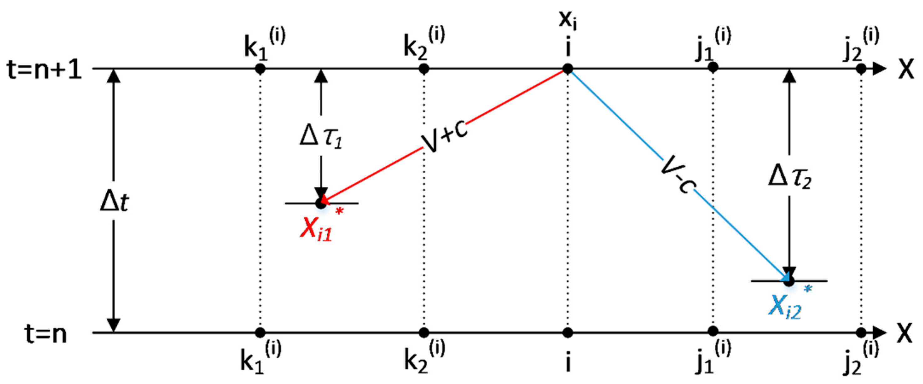
CAMP1DF uses the hybrid Lagrangian-Eulerian (semi-Lagrangian) method to solve the DYW module. Unstructured meshes generated by finite element method are implemented. The backward track procedure is illustrated in Figure 2. We integrate Equations (3) and (4) along their respective characteristic lines from xi, which is the coordinate of node i, at the new time level to x*i1 and x*i2, which show the location of a fictitious particle tracked backward from xi along the first and second characteristics. The derivation is illustrated in detail in the work of Shih and Yeh (2018) [10]. Tracking time can be obtained via a backward track method along their first ( Δ τ 1 ) and second ( Δ τ 2 ) respective characteristics. To ignore the eddy diffusion effects, Equations (3) and (4) can be further expressed as follows:
( V i + ω i ) ( V i 1 * + ω i 1 * ) Δ τ 1 = 1 2 ( ( K + ) i V i + ( K + ) i 1 * V i 1 * ) + 1 2 ( ( S + ) i + ( S + ) i 1 * ) ,
( V i ω i ) ( V i 2 * ω i 2 * ) Δ τ 2 = 1 2 ( ( K ) i V i + ( K ) i 2 * V i 2 * ) + 1 2 ( ( S ) i + ( S ) i 2 * ) ,
where subscript (i) represents a node, and superscript (n) denotes the time level; Vi and ωi are the values of V and ω at xi at a new time level, respectively; Vi1* and ωi1* are the values of V and ω at point xi1*, respectively; (K+)i and (S+)i are the values of K+ and S+, respectively, at node i at a new time level; (K+)i1* and (S+)i1* are the values of K+ and S+, respectively, at node xi1*; Vi2* and ωi2* are the values of V and ω at point xi2*, respectively; (K)i and (S)i are the values of K and S, respectively, at node i at a new time level; and (K)i2* and (S)i2* are the values of K and S, respectively, at node xi2*. The primary variables are calculated through interpolations at both their new and previous time levels.
V i 1 * = a 1 ( i ) V k l ( i ) ( n ) + a 2 ( i ) V k 2 ( i ) ( n ) + a 3 ( i ) V k l ( i ) + a 4 ( i ) V k 2 ( i ) ,
ω i 1 * = a 1 ( i ) ω k l ( i ) ( n ) + a 2 ( i ) ω k 2 ( i ) ( n ) + a 3 ( i ) ω k l ( i ) + a 4 ( i ) ω k 2 ( i ) ,
V i 2 * = b 1 ( i ) V j l ( i ) ( n ) + b 2 ( i ) V j 2 ( i ) ( n ) + b 3 ( i ) V j l ( i ) + b 4 ( i ) V j 2 ( i ) ,
ω i 2 * = b 1 ω j l ( i ) ( n ) + b 2 ω j 2 ( i ) ( n ) + b 3 ω j l ( i ) + b 4 ω j 2 ( i ) ,
where k1(i) and k2(i) are the two nodes of the element in which the backward tracking from node i, along the first characteristic, stops; j1(i) and j2(i) are the two nodes of the element in which the backward tracking from node i, along the second characteristic, stops; and a1(i), a2(i), a3(i), a4(i), b1(i), b2(i), b3(i), and b4(i) are the interpolation parameters associated with the backtracking of the i-th node, all within the range [0,1].
It is noted that either tracking time or distance should be employed to determine whether to stop the tracking sequence. Simulation coefficients and forcing terms (source and sink terms) have a functional dependency on the above varying variables. These terms can be calculated because the primary variables are obtained through backward tracked. More details regarding the numerical approximation can be obtained from Shih and Yeh (2018) [10].
A hybrid Lagrangian–Eulerian method adopting finite element meshes is also employed for the case of DIW and KIW flows. Using the definition of the cross-sectional average discharge, Equation (2) can be described in the following Lagrangian form:
D V A D τ + V A x = 0 ,
The characteristic line from the new time level is obtained from the previous time level or boundary. It can be formulated as
( 1 + Δ τ 2 K i ( n + 1 ) ) A i ( n + 1 ) = ( 1 Δ τ 2 K i * ) A i * .
The tracking time should be equal to the calculated time step as the characteristic root is obtained. It may be less than time step as the tracking reaches the boundary. The above equation is considered a linear hyperbolic problem with the nonlinear effects evaluated using the cross-sectional area at a previous time. Therefore, it can be essentially treated as a nonlinear hyperbolic problem. The cross-sectional area will be iteratively obtained. The water depths at all interior nodes are interpolated via the implemented function.
For using the Lagrangian method to solve the KIW equation, all the assumptions in the DIW approach are retained, except Sf = S0.

3. Model Calibrations

Analytic benchmark solution for open-channel flows derived by MacDonald et al. (1997) [30] are applied to evaluate the accuracy of the proposed CAMP1DF model. MacDonald et al. (1997) [30] illustrated four open-channel flow cases with a fixed upstream discharge and Dirichlet-type downstream boundary conditions. Cases 1 and 2 are rectangular channels, and cases 3 and 4 are trapezoidal. The subcritical fluvial condition is designed in cases 1 and 3, but case 3 presents the frequent oscillations of wave propagation. Cases 2 and 4 are subcritical and supercritical changed flows, whereas case 4 illustrates a hydraulic jump. More details are presented in MacDonald et al. (1997) [30].

3.1. Calibration of the Fully Dynamic Wave Module

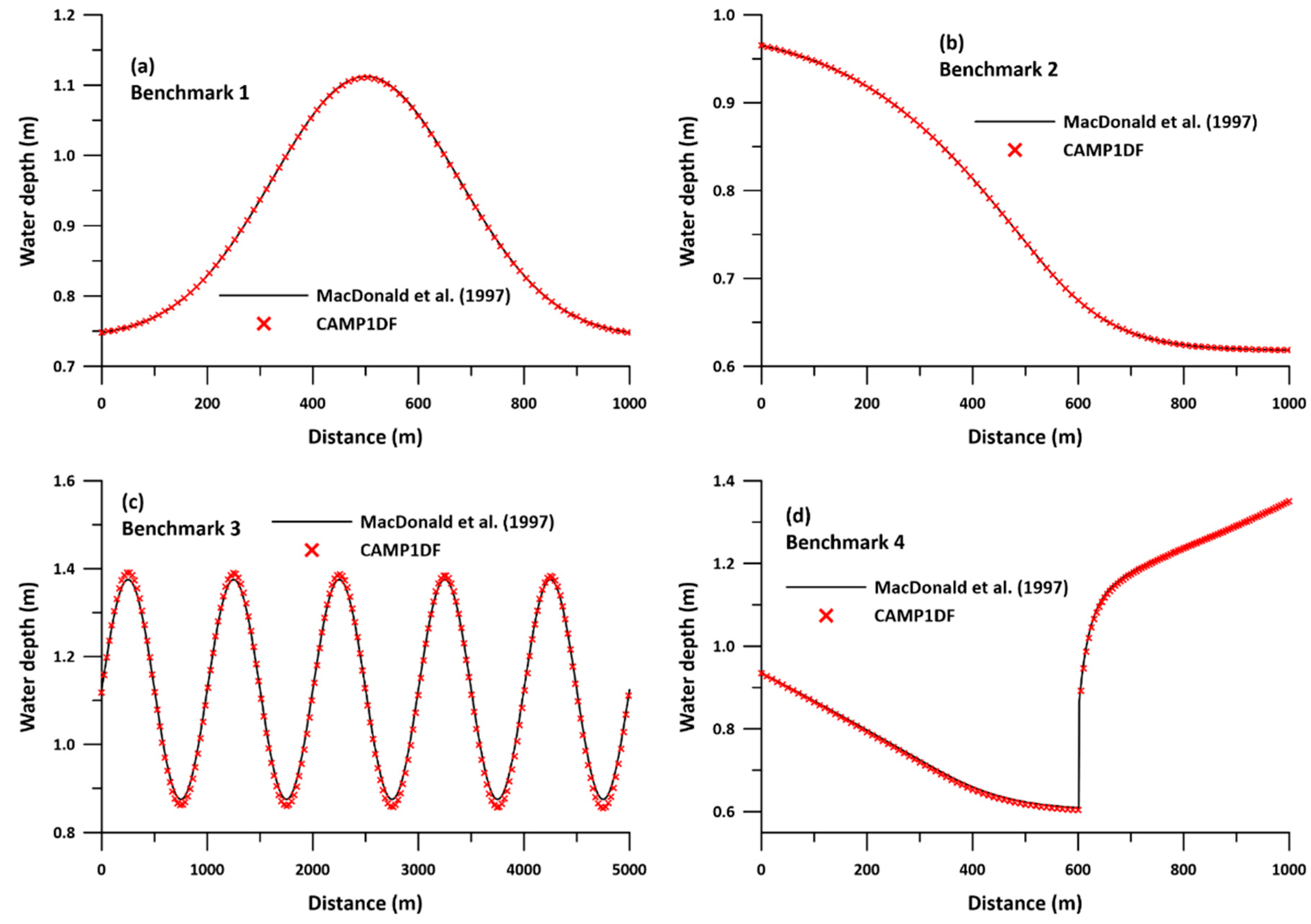
The calculation errors of the DYW model relative to the analytic results are shown in Table 1, and the simulations of hydrograph are revealed in Figure 3. The abscissa represents the distance along the river, and the ordinate represents the water depth. The black line shows the benchmark solutions calculated by MacDonald et al. (1997) [30], and the crosses indicate the DYW simulations by CAMP1DF. Error analysis to evaluate mean errors (εmean) and to enlarge error discrepancy via weighting quadratic terms (root mean square error, RMSE) is performed. The variability on relations (Pearson’s coefficient, C2), goodness-of-fit efficiency (Nash–Sutcliffe efficiency, R2), and Theil’s prediction/inequality coefficient (U2) of paired simulations and analytics are performed.
Figure 3 shows that the simulated hydrograph agrees with analytical solutions very well in all benchmark cases. Practically identical hydrographs are revealed. Table 1 also indicated that the discrepancy between CAMP1DF simulations and benchmark values is very small. First, the benchmark case is a subcritical flow problem. CAMP1DF very well captures the sharp front, both in peak time and in value. The model has a very good potential to solve subcritical fluvial propagation problem. Case 2 is a fluvial condition that changes from subcritical to supercritical. Nearly the same results of the simulations and the analytics are identified because the CAMP1DF uses the sub-element tracking method with monotonic shape-preserving interpolation [12,34]. The result verified that the mixed subcritical and supercritical fluvial problem can be solved by CAMP1DF without difficulty. CAMP1DF demonstrated a good capability to perform good matches to the frequent wave oscillations problem of case 3. The error calculation yields a very small difference between the simulations and analytics in terms of peak error (εp = −0.0125). The indicators of the wave propagation trend, i.e., C2, R2, and U2, display the agreement between the CAMP1DF simulation and analytical data. For the fluvial transition problem of case 4, in which the subcritical to supercritical flow with a hydraulic jump, CAMP1DF also exhibits a significant agreement with the benchmark results and precisely captures the hydraulic jump. In short, the above DYW simulation results show a near perfect match to those of the analytical solutions in all the cases. The results indicate that the CAMP1DF model can accurately consider all types of transient fluvial problems between subcritical and supercritical flows in these benchmark problems.

3.2. Calibration of Diffusion Wave Module

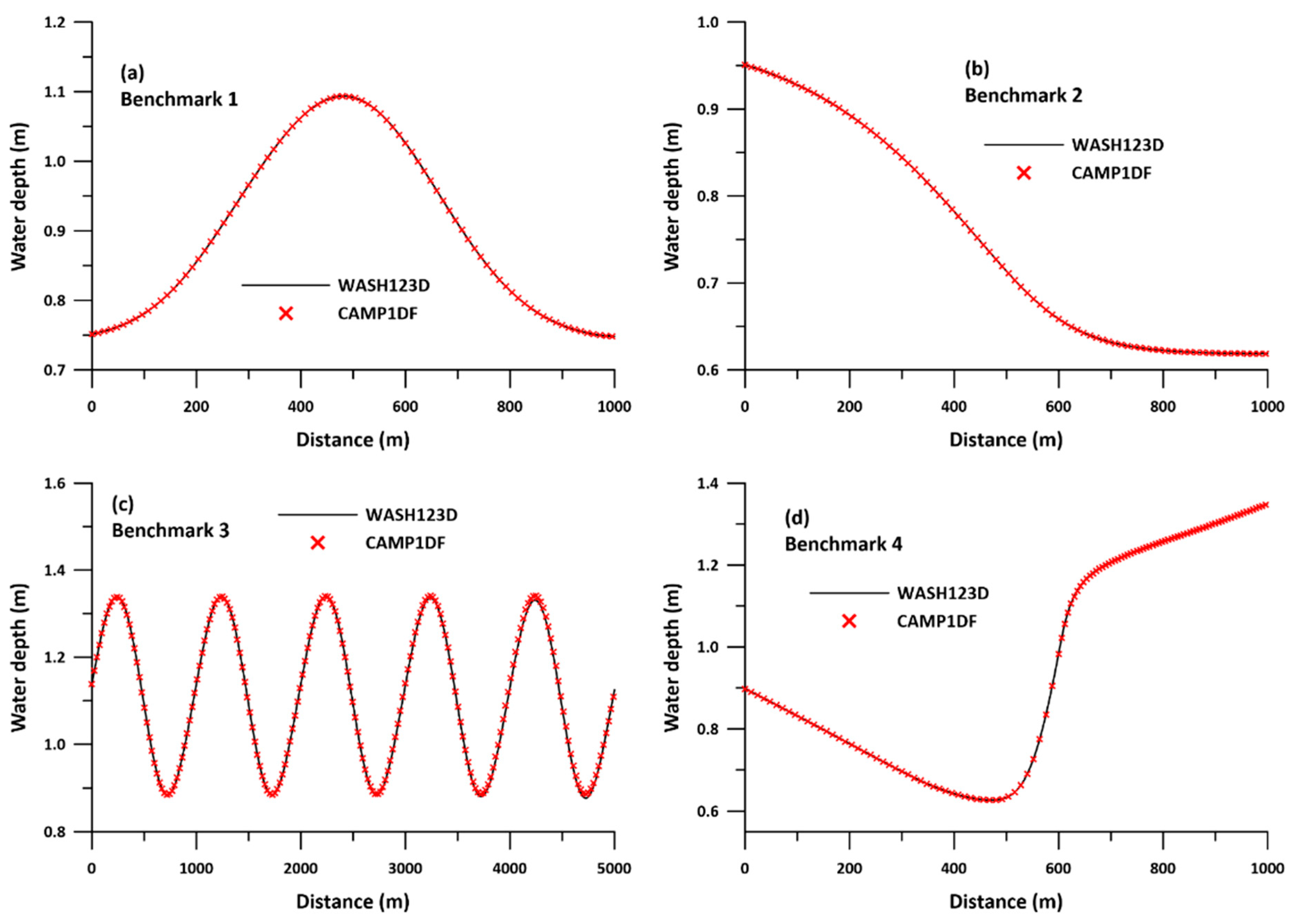
Because there is no analytical derivation of the DIW flow, the numerical results simulated by WASH123D are selected to validate the accuracy of the CAMP1DF DIW module. The WASH123D was originally developed by Yeh G. T. in 1998. WASH123D has been applied for many issues, for example in everglade restoration, flood forecasts, wetland protection, ecosystem restoration, coast inundation, groundwater resources, etc. [10,35,36,37,38]. The WASH123D model has been verified for numerous applicable cases; its DIW routing module can be considered reliable.
The same benchmark problems of MacDonald et al. (1997) [30] are examined in this study. The comparisons between the CAMP1DF DIW module and WASH123D simulations are shown in Figure 4, where the x-axis, y-axis, and plotting notations are as same as those in Figure 3. The errors for these two models simulations are listed in Table 2. Figure 4 shows a very good agreement between these two simulations for all the cases. For benchmark problems 1 and 2, all the error indicators of the mean errors and their biases are shown to be almost identical for the paired CAMP1DF DIW and WASH123D modeling results. Both εmean and RMSE indicate the presence of very minor errors, within 1.0D-3 m, for the rest of the cases. Moreover, the error indicators of C2, R2, and U2 all suggest that the values from the CAMP1DF DIW and WASH123D simulations are nearly identical. Thus, the CAMP1DF simulation is demonstrated to offer the same simulation trend as the WASH123D simulations for all four open-channel flow problems. Briefly, the DIW simulation module shows a nearly perfect match to the WASH123D simulations in all the cases, where the true values are assumed. The results indicate that the CAMP1DF model can accurately implement DIW routing results of transient flow between subcritical and supercritical flows in these benchmark problems.

3.3. Calibration of Kinematic Wave Module

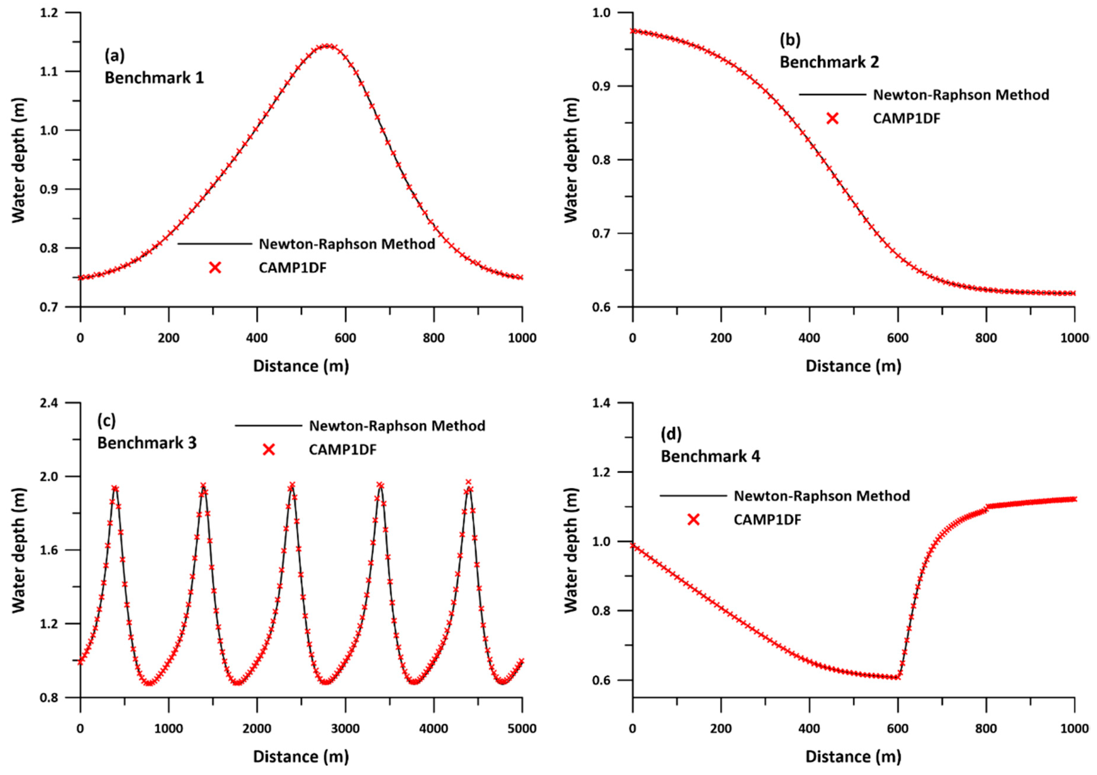
The assumption in the KIW approach is that the hydraulic gradient is equal to the gradient of the riverbed, i.e., S0 = Sf. MacDonald et al. (1997) [30] examined two types of cross-sectional geometries: a rectangular channel in cases 1 and 2 and a trapezoidal channel in cases 3 and 4. Therefore, we used Manning’s equation, expressed as follows, solved by the Newton–Raphson method to estimate the analytic solutions.
Q = A 1 n R 2 3 S 0 1 2 ,
where n is Manning’s coefficient, R is the hydraulic radius, and S0 is the hydraulic gradient.
For the case of a rectangular cross-section, Equation (18) could be extended to differential forms as follows:
  f ( h ) = Q n B ( S 0 ) 1 2 ( 1 h + B 2 ) 2 3 h  
  f ( h ) = Q n B ( S 0 ) 1 2 [ 2 3 ( 1 h + B 2 ) 1 3 ( 1 h 2 ) ] 1  
where f(h) is a function of shifting all terms to the right hand side; and its differential result is expressed as f’(h). For benchmark case 3, a 5-km long trapezoidal channel (T = 10 + 4y, P = 10 + 2y 5 ) was designed. Its differential form is derived as
  f ( h ) = ( Q n S 0 ) 3 5 ( B + 2 5 h ) 2 5 ( B + 2 h ) h  
  f ( h ) = ( Q n S 0 ) 3 5 [ 4 5 5 ( B + 2 5 h ) 3 5 ( B + 2 h ) 2 ( B + 2 5 h ) 2 5 ( B + 2 h ) 2 ] 1  
For case 4 of a trapezoidal channel with an angle of 45° between the ground and hypotenuse, the derivations are
  f ( h ) = ( Q n S 0 ) 3 5 ( B + 2 2 h ) 2 5 ( B + h ) h  
  f ( h ) = ( Q n S 0 ) 3 5 [ 4 2 5 ( B + 2 2 h ) 3 5 ( B + h ) ( B + 2 2 h ) 2 5 ( B + h ) 2 ] 1  
Then we used the Newton–Raphson method to solve f(h) = 0 for h via the convergence of iterations. The solutions can be obtained when the updated error of the water stage is less than the convergence criterion during the nonlinear iterations. These results are fine approximations of the analytical solutions of the KIW approximation.
The cases provided by MacDonald et al. (1997) [30] are examined for evaluating the accuracy of the CAMP1DF KIW module. The comparisons between the CAMP1DF KIW simulations and solutions of Manning’s equation obtained by the Newton–Raphson method are shown in Figure 5, and the errors in the CAMP1DF numerical simulations and Newton-Raphson approximation are listed in Table 3. In Figure 5, the x-axis, y-axis, and plotting notations are the same as those in Figure 3. It is can be obviously seen in Figure 5 that the results of these two approximations are almost identical in all the cases. For all the benchmark problems, not only the mean errors (εmean) or quadratic errors (RMSE) but also their variabilities and prediction trends (C2, R2, and U2) revealed nearly fitting estimations of the paired CAMP1DF KIW and Newton–Raphson approximation results. In short, in all the cases, the KIW simulation module shows a near perfect match to the numerical approximation results obtained by the Newton-Raphson method. The results demonstrate that the CAMP1DF model can implement an accurate KIW routing for the nonprismatic cross-section, nonuniform bed slope, and transient flow scenarios between subcritical and supercritical flows in the benchmark problems.

4. Result and Discussions

In this section, the inertia effects of open channel flow are discussed. The examples provided by MacDonald et al. (1997) [30] are examined as prismatic cases, and the Zhuoshui Creek basin located in central Taiwan is taken as a nonprismatic example. More detailed discussions are presented below.

4.1. Discussion on Prismatic Cases

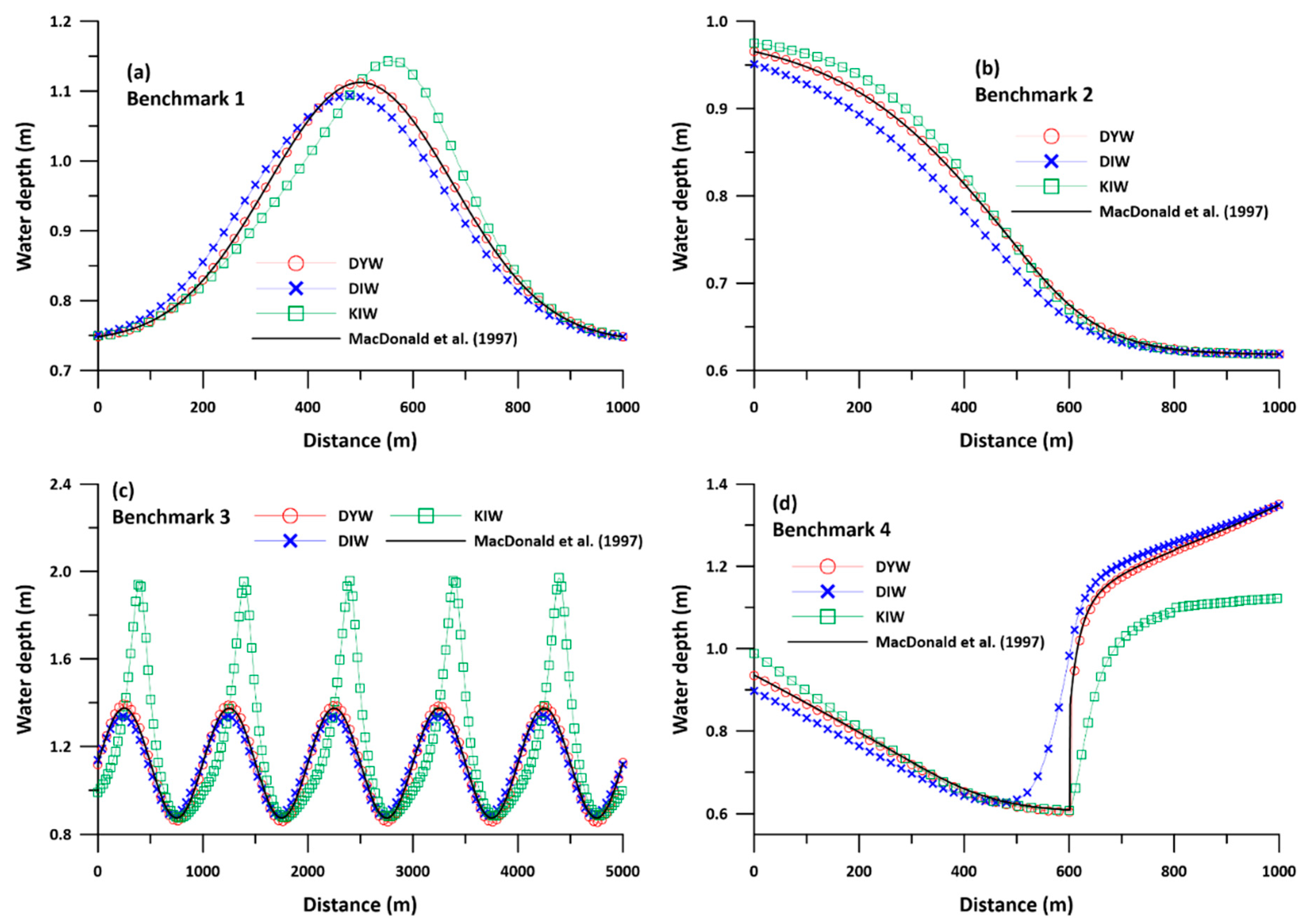
The accuracy of the DYW, DIW, and KIW flow modeling by CAMP1DF is demonstrated by the abovementioned calibrations. In this section, the comparisons between the simulation results and analytics solutions of DYW, DIW, and KIW approximations are plotted in Figure 6, where the x- and y-axis are defined in a manner similar to the previous figure. The black line represents the analytical solutions calculated by MacDonald et al. (1997) [30], the circle dots with a red line represent the DYW simulations, the cross dots with a blue line depict the DIW simulations, and the rectangular dots with green line represent the KIW simulations of CAMP1DF. The modeling errors in DYW/DIW/KIW and the analytic derivation are listed in Table 4. Both the hydrograph and the error calculations clearly indicate that the DYW simulation achieves the most accurate results, whereas the KIW flow has the largest discrepancies. The simulation results in Figure 6a clearly exhibit that the KIW flow simulation overestimates the flow peak by 3%, whereas the DIW wave underestimates it by 2%. However, the KIW flow predicts peaks with a 5% discrepancy along the x-direction. The hydrograph of KIW reveals a positive skew pattern compared with the analytical solution. The DIW simulation slightly underestimates the results, and a negative skew is obtained from the analytics. Only the DYW approximation can simulate the flow peak and its occurrence without difficulty. Thus, only considering the friction loss and gravity effects easily tend to misestimate the hydrograph. Combining the pressure effects in the momentum equation will improve the simulation accuracy and extensively ameliorate the peak time. Including the inertial terms, such as in the DYW approximation, can catch flow peak and its occurrence without difficulty. On further examination of the error estimations, the error indicators εmean and RMSE indicate that the inertial effects are important to subcritical routing. The flow pattern related errors, i.e., C2 and R2, suggest that the acceleration term plays an important role in this example. It is also noted that the simulation time of DYW is 1.3 times that of KIW and almost as the same as the DIW routing. Therefore, using DYW to solve this case can provide both efficiency and accuracy in achieving the solution.
Case 2 reveals that the bed slope is steep at 500 m from the upstream, and the fluvial conditions are changed from subcritical to supercritical. The result shown in Figure 6b suggests that the DYW simulations yield the most accurate results, the KIW results in a slight overestimation, and the DIW underestimates at the upstream boundary. It is noted that the DIW simulations has twice the εmean and RMSE of the KIW simulations. Therefore, the upstream boundary effects play an important role in this case. The error indicators of the flow pattern, i.e., C2, R2, and U2, yield similar trends for the two modules. The DYW flow clearly provides the most accurate simulations among the three approximations; however, it also spends 1.42 times the calculation time of the KIW flow and 1.23 times that of the DIW flow. In short, these three approaches can all achieve good simulations of the subcritical and supercritical transform problems because the proposed approximation utilizes sub-element tracking with monotonic shape-preserving interpolation, and the inertial effects are not obvious in this case.
Case 3 presents a subcritical flow with sequent oscillations in the entire fluvial flow. The result shown in Figure 6c demonstrates that the DYW/DIW simulations have a slight discrepancy from the analytical solutions despite the KIW simulation. The KIW flow has almost twice the depth errors compared with the analytical solution. Both DYW and DIW yield reasonable hydrographs, with negative mean bias differences (εmean) at slightly lower water levels obtained relative to the analytics. Error indicators of C2 and R2 depict the agreement between the simulations and analytics for these two approaches. The simulations are confirmed to reveal a good flow pattern in this oscillating open-channel problem. However, the water depths reveal a large discrepancy in the KIW routing. Therefore, the inertia and gravity terms are important in this wave oscillation problem.
Case 4 is a flow that transitions from supercritical to subcritical with an occurrence of hydraulic jump. The result is shown in Figure 6d. The simulated hydrograph of DYW exhibits good agreement with the analytical solutions. It is also noted that the εmean and RMSE indicate the DYW has smaller errors among the three options. The KIW flow has a significant error in the downstream jet, whereas the DIW flow yields an inaccurate result around the hydraulic jump. Only the DYW flow reveals a near exact agreement at the location of the hydraulic jump. Error indicators of the mean errors and biases or variabilities all reveal slightly discrepancies between the simulations and analytical derivations. Therefore, the fluid condition of a subcritical/supercritical fluid transfer with a hydraulic jump confirms that only considering the inertial effect can yield accurate results.
The above simulations confirm that the DYW flow can precisely consider any transition flows between the subcritical and supercritical flow benchmark problems. The DIW approximation, which neglects the inertial acceleration, can reasonably simulate the fluvial flow, except for an abrupt condition, such as a hydraulic jump problem. The KIW flow based on the simplest assumption tends to yield the most discrepancy in the results. However, KIW costs the least simulation time, and there is no need to assign a downstream boundary; therefore, it may be more feasible for field applications.

4.2. Discussion of Nonprismatic Cases

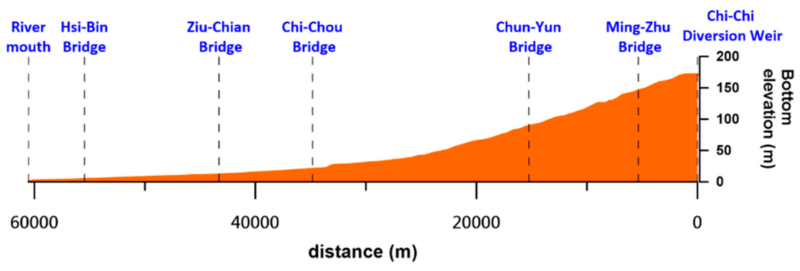
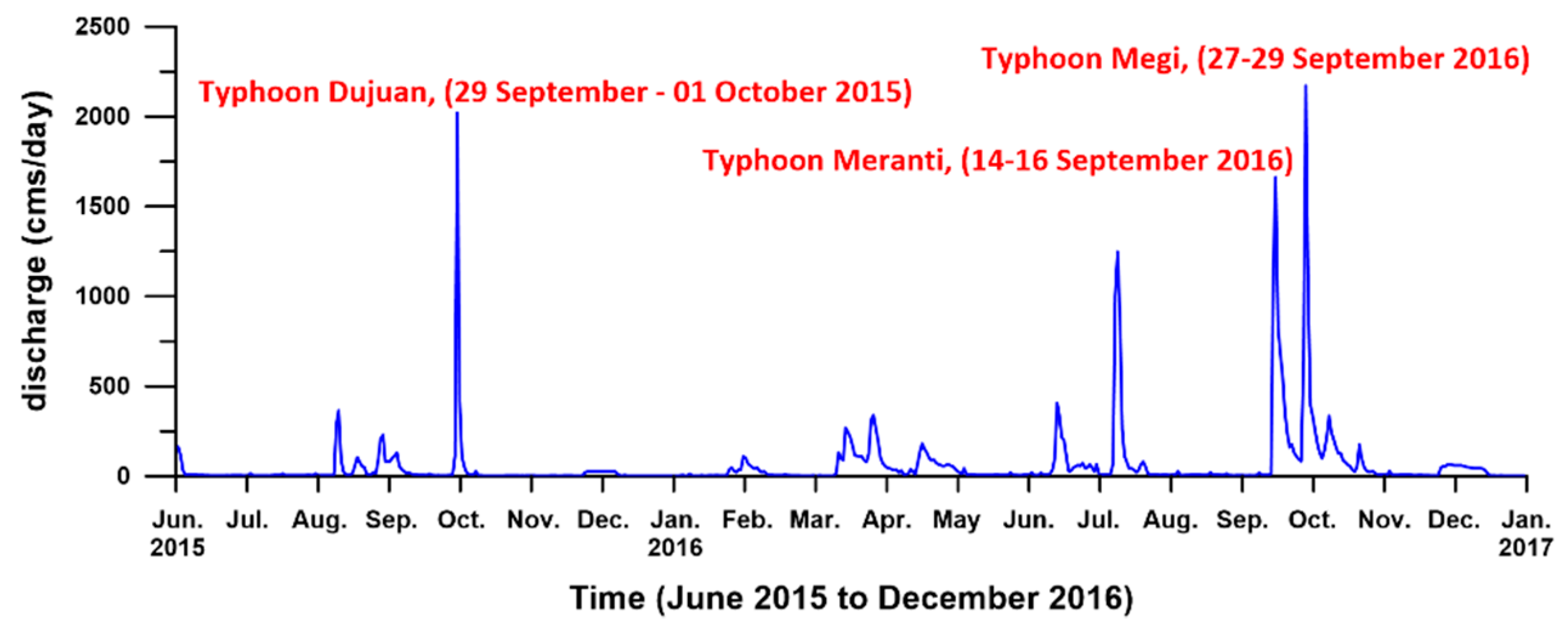
In the study, the Zhuoshui River was selected to test the inertial effects of the field fluvial problem. The Zhuoshui River alluvial fan located in central Taiwan formerly had abundant groundwater resources and was labeled one of the most important feeding areas in agriculture. Because of the over-pumping of groundwater in the past few decades, critical issues of land subsidence and degradation of groundwater environments, such as seawater intrusion and contamination, have arisen in the Zhuoshui River alluvial fan. The rainfall distribution in the river alluvial fan has large spatial and temporal variations, causing significant wet and dry season differences that limit the development of new water resources, and thus, leads to significant challenges in their management. The Chi-Chi diversion weir located in the Zhuoshui River was constructed to better control the discharges and efficiently support sustainable development in the water resources. The Zhuoshui River is considered as a good example to study inertial effects for a nonprismatic cross-sectional transient flow because the Chi-Chi diversion reasonably controls the discharges from the upstream side, and it has a total of five gauge stations with observation stages for tracking the fluvial flow, as shown in Figure 7. In addition, three heavy typhoon-induced floods that occurred in the recent years were selected for study, as shown in Figure 8. The models of the cross-sections of the Zhuoshui River are constructed from the latest field geometry measurement, and Manning’s coefficients (Mn) are obtained from the official investigations conducted by the Fourth River Management Office, Water Resource Agency of Taiwan. A total of 137 cross-sections and five Manning’s coefficients, varying from 0.040 to 0.027, are obtained.
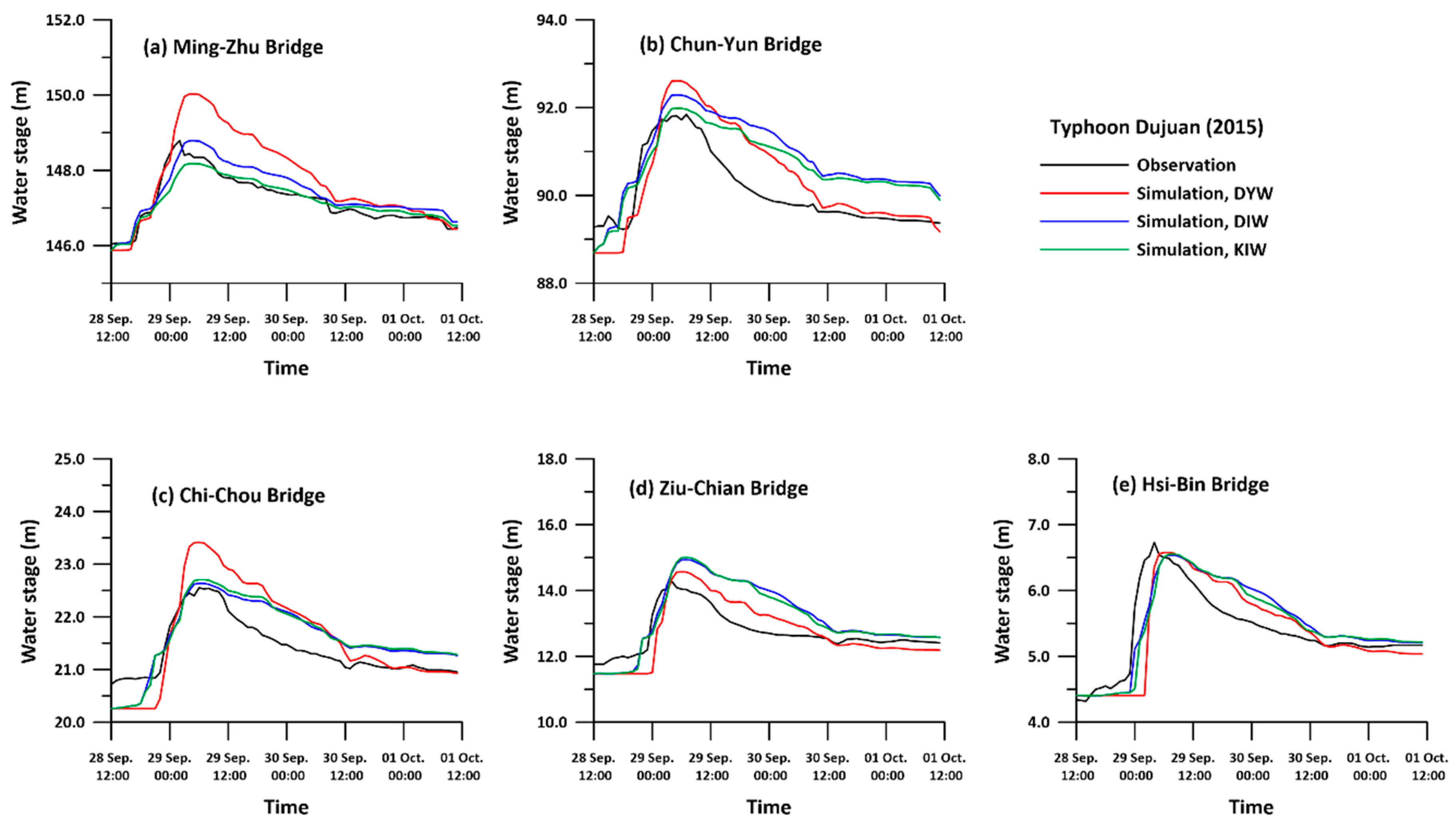
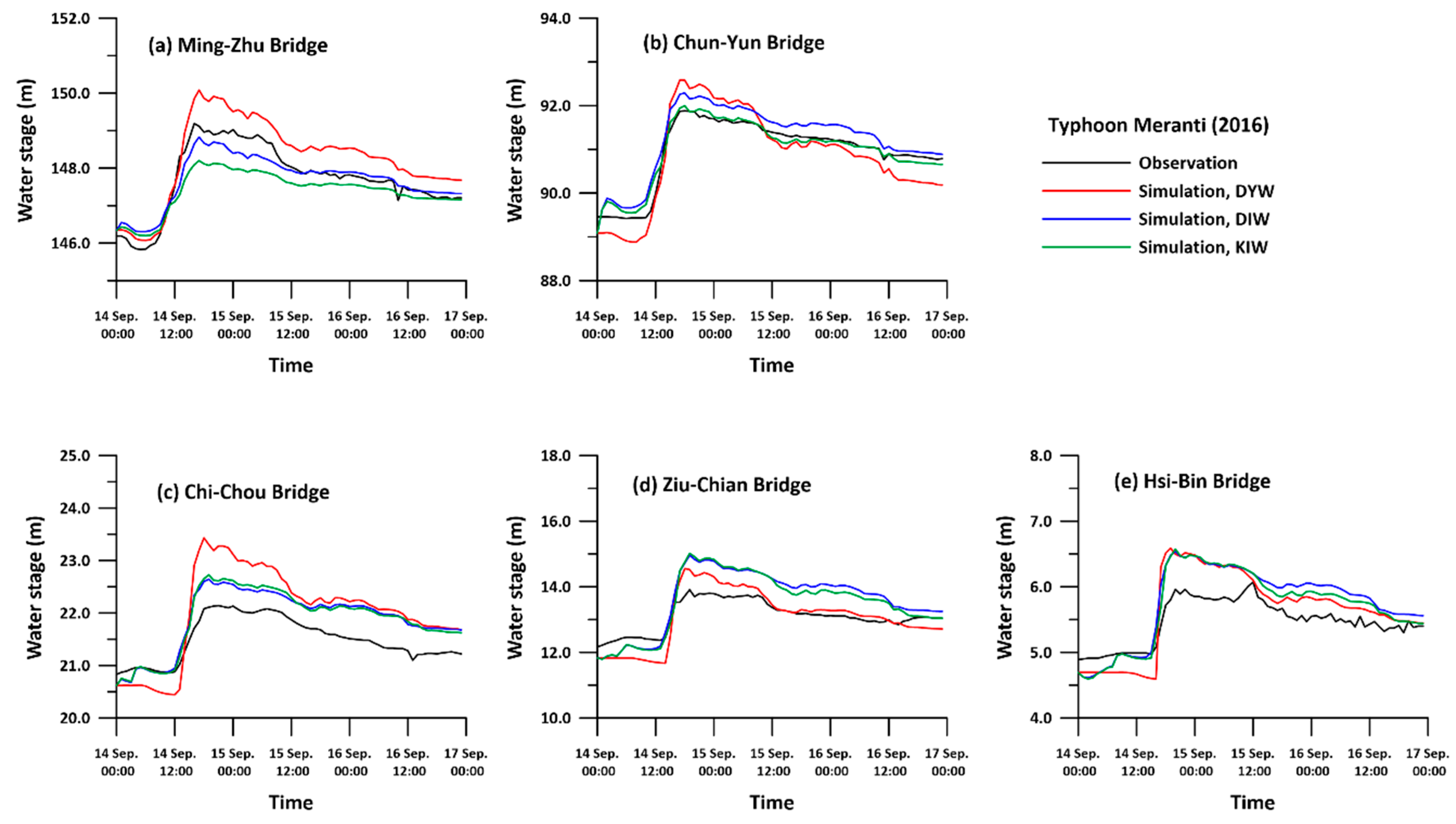
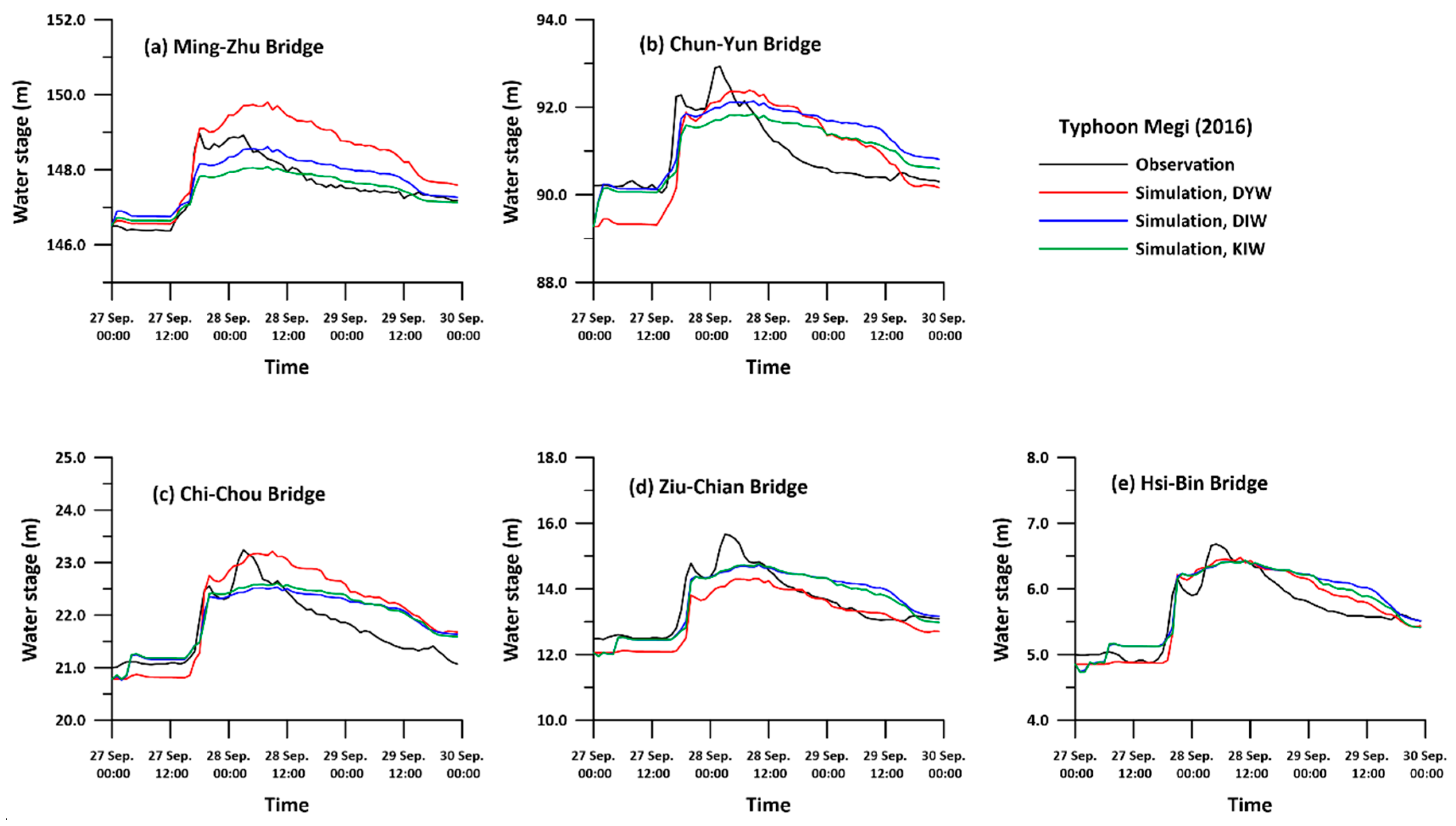
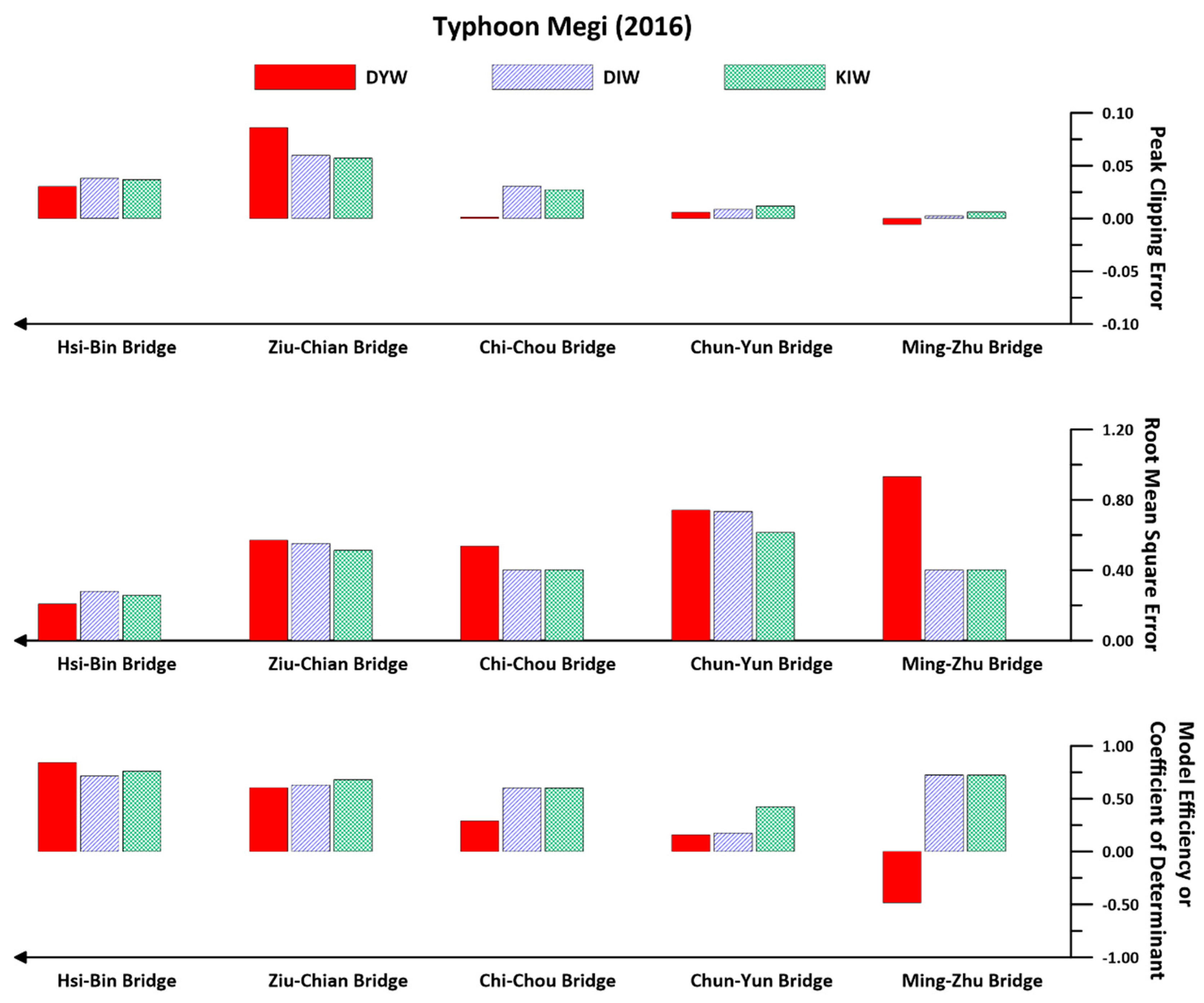
The three extreme typhoons of Dujuan (2015), Meranti (2016), and Megi (2016) are simulated. The results of the DYW/DIW/KIW flows are compared with the observation stage results in Figure 9, Figure 10 and Figure 11, in which the abscissa is the simulation time and the ordinate axis is the water stage. The black line represents the observations, and the red/blue/green lines represent the simulations of DYW/DIW/KIW. Figure 9 shows the simulations of Typhoon Dujuan (2015). The simulations reveal a reasonable hydrograph among all the approaches. It is noted that all the simulations are in good agreement with the observations for both the rising and receding limbs. The flow peak is also captured well along the river. The flow patterns of DIW and KIW are similar; however, the flow peak is overestimated by DYW in some upstream stations. Figure 10 and Figure 11 also show that the DIW and KIW simulations have a similar pattern and smaller discrepancies for the various bridges. This result indicates that the pressure term influence on the water stage in the nonprismatic, nonuniform riverbed problem is minor. The DYW flow, however, reveals a more sensitive vibration in the water stage. The water stage rises and recesses more dramatically than in the other two approaches. Therefore, the inertial acceleration tends to cause a sensitive water stage variation. This phenomenon is understandable from a physical perspective. However, the simulation of DYW does not ensure the most accurate results, despite it having the most physical relevance, because the Zhuoshui River in Taiwan is labeled as meandering and its riverbed is stepped. However, because of the limited investigations, each cross-sectional geometry is measured at approximately 500–1000 m intervals every 5 years. This result implies that using field-investigated cross-sections to implement channel routing may lead to some uncertainties. The modeling uncertainty will be exaggerated with the complexity of the geometries between two cross-sections. Thus, Manning’s coefficients are utilized as a strategy to rationalize the answers, even though they should have a physical meaning in the routing. In the example of the His-Bin Bridge, a station located at the downstream of the Zhuoshui River is much flatter compared to others. Therefore, its acceleration-induced inertial effects are minor. Thus, the three approaches have similar simulated water stages at the His-Bin Bridge. In comparison, stepped riverbeds, such as those at the Ming-Zhu Bridge, Chun-Yun Bridge, and Chi-Chou Bridge, tend to have obvious inertial effects.
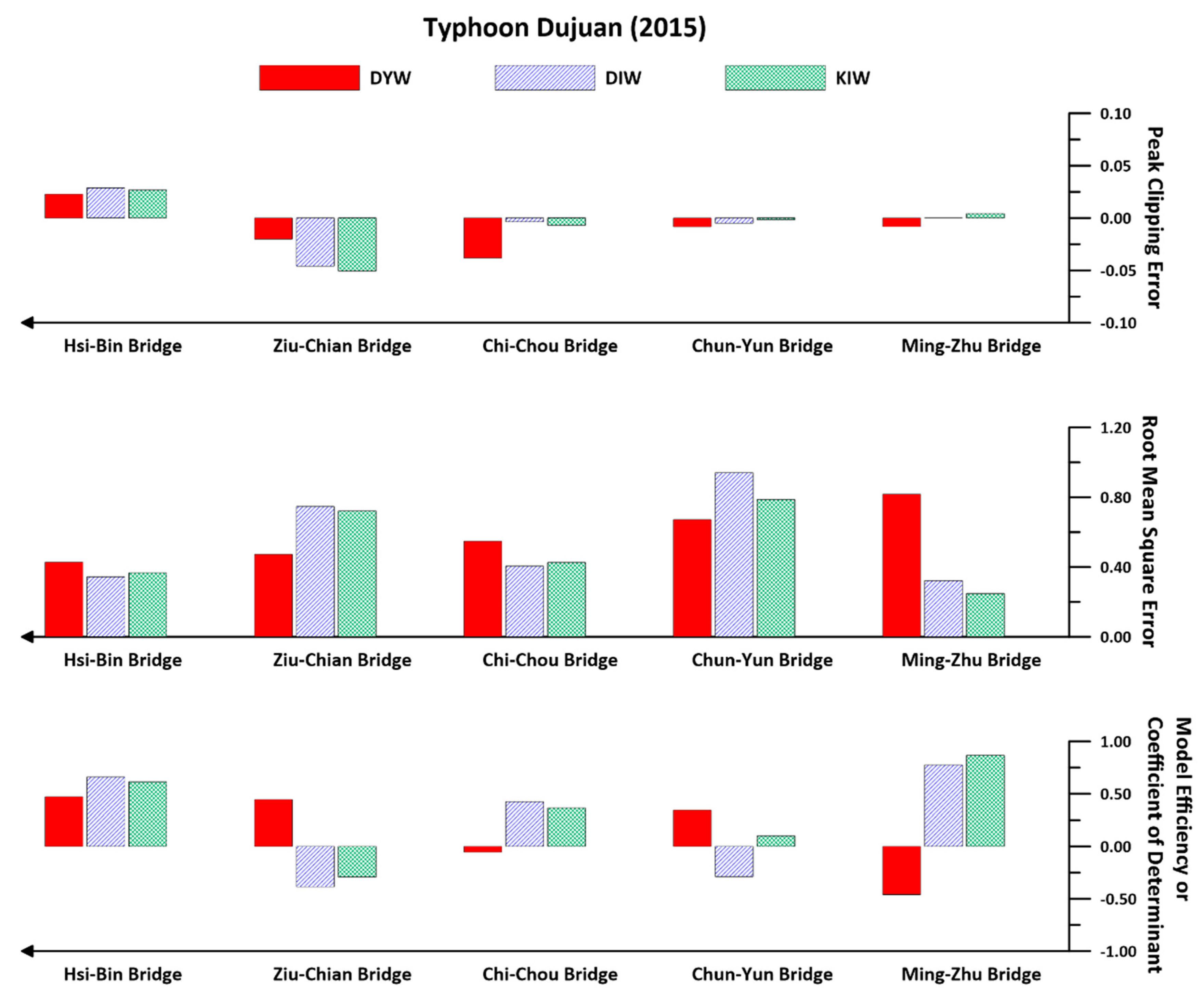
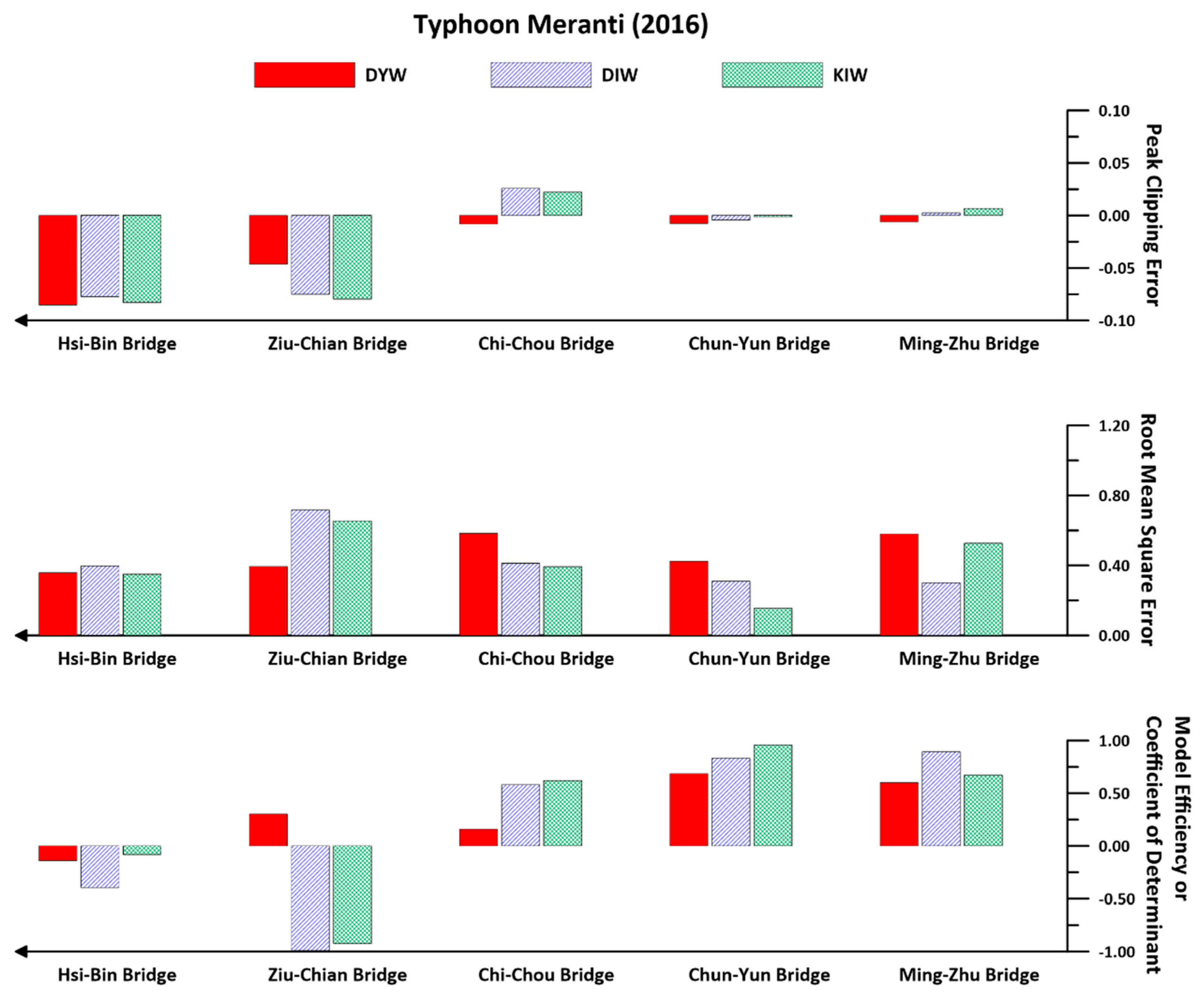
Figure 12, Figure 13 and Figure 14 display the DYW/DIS/KIW simulation errors related to the observations of the study events. The errors are found to be chaotic. For example, the Ziu-Chian Bridge performs poorly with DYW routing, whereas the Ziu-Chian Bridge exhibits good results. There is significant uncertainty in the rivers of Taiwan. Regarding the numerical approximation, it is clear that DYW requires the most computation time to achieve numerical convergence, i.e., it spends the longest simulation time among the three approaches. Therefore, DYW may not fit the requirement of real-time simulations such as flood forecasting or disaster mitigation. According to the above simulation, the time difference in the calculations from the three approximations is within a couple of seconds. Thus, the calculation is not an issue for convergence integration. Even though the DYW wave cannot ensure achievement of the most accurate results, it yields the most reasonable response hydrograph, including the inertial effects. The simulation accuracy may then be adjusted by tuning the Manning’s coefficients. Another important point to consider is that the DYW wave does not ensure achievement of numerical convergence for nonprismatic and nonuniform field riverbed problems if the physical assumptions are not satisfied. The KIW flow satisfies the uniform flow assumption, and the absence of the requirement of a downstream boundary is an advantage for field cases.

5. Conclusions

This study developed a numerical model, CAMP1DF, to use the characteristics-based particle tracking method to solve one-dimensional fully dynamic wave, diffusion wave, and kinematic wave flow problems. The solutions to benchmark problems confirmed the accuracy of CAMP1DF in this study. The proposed scheme not only allows a large time step size but also solves half of the simultaneous algebraic equations. Simulations of accuracy and efficiency are both improved. The simulations further indicated that the dynamic wave approach clearly yielded the most accurate results among all the approximations. The inertial effects (particularly in sharp riverbeds), such as hydraulic jumps, were identified to be important. In an oscillation problem, the kinematic wave flow was found to have twice the depth errors as that of the others. A field nonprismatic case of the Zhuoshui River in central Taiwan showed that the dynamic wave approach did not ensure a better performance than the other two approximations. However, the dynamic wave approach clearly yielded a reasonable response because of the inclusion of the inertial effect; its simulation accuracy could be improved by adjusting Manning’s coefficients. The kinematic wave flow was found to satisfy the uniform flow assumption and did not require a downstream boundary, making it advantageous for field cases.

Author Contributions

D.-S.S. conceived and designed the study, performed the model simulations, and wrote the paper. G.-T.Y. provided the comments of theoretical and numerical approximations.

Funding

This research is founded by the Ministry of Science and Technology, Taiwan, under Grant no. MOST-106-2621-M-005-006.

Conflicts of Interest

The authors declare no conflict of interest.

References

  1. Chow, V.T. Open Channel Hydraulics; McGraw Hill: New York, NY, USA, 1959. [Google Scholar]
  2. Chow, V.T.; Maidment, D.R.; Mays, L.W. Applied Hydrology; McGraw-Hill: New York, NY, USA, 1988. [Google Scholar]
  3. Yen, B.C.; Tsai, C.W.-S. On noninertia wave versus diffusion wave in flood routing. J. Hydrol. 2001, 244, 97–104. [Google Scholar] [CrossRef]
  4. García-Navarro, P.; Alcrudo, F.; Savirón, J.M. 1-D Open-Channel Flow Simulation Using TVD-McCormack Scheme. J. Hydraul. Eng. 1992, 118, 1359–1372. [Google Scholar] [CrossRef]
  5. Aral, M.M.; Zhang, Y.; Jin, S. Application of Relaxation Scheme to Wave-Propagation Simulation in Open-Channel Networks. J. Hydraul. Eng. 1998, 124, 1125–1133. [Google Scholar] [CrossRef]
  6. Vukovic, S.; Soptab, L. ENO and WENO Schemes with the Exact Conservation Property for One-Dimensional Shallow Water Equations. J. Comp. Phys. 2002, 179, 593–621. [Google Scholar] [CrossRef]
  7. Zhu, D.; Chen, Y.; Wang, Z.; Liu, Z. Simple, Robust, and Efficient Algorithm for Gradually Varied Subcritical Flow Simulation in General Channel Networks. J. Hydraul. Eng. 2011, 137, 766–774. [Google Scholar] [CrossRef]
  8. Ponce, V.M.; Theurer, F.D. Accuracy Criteria in Diffusion Routing. J. Hydraul. Div. 1982, 108, 747–757. [Google Scholar]
  9. Sivaloganathan, K. Channel Flow Computations Using Characteristics. J. Hydraul. Div. 1979, 105, 899–910. [Google Scholar]
  10. Shih, D.S.; Yeh, G.T. Using a characteristic-based particle tracking method to solve one-dimensional fully dynamic wave flow. Comput. Geosci. 2018, 22, 439–449. [Google Scholar] [CrossRef]
  11. Suk, H.; Yeh, G.T. A multi-dimensional finite element particle tracking method for solving complex transient flow problems. J. Hydrol. Eng. 2009, 14, 759–766. [Google Scholar] [CrossRef]
  12. Williamson, D.L.; Rasch, P.J. Two-dimensional semi-Lagrangian transport with shape-preserving interpolation. Mon. Weather Rev. 1989, 117, 102–129. [Google Scholar] [CrossRef]
  13. Yen, B.C. Open-Channel Flow Equations Revised. J. Eng. Mech. Div. ASCE 1973, 99, 979–1009. [Google Scholar]
  14. Ponce, V.M.; Simons, D.B.; Li, R.M. Applicability of Kinematic and Diffusion Models. J. Hydraul. Div. 1978, 104, 353–360. [Google Scholar]
  15. Cozzolino, L.; Pepe, P.; Morlando, F.; Cimorelli, L.; D’Aniello, A.; Morte, R.D.; Pianese, D. Exact Solution of the Dam-Break Problem for Constrictions and Obstructions in Constant Width Rectangular Channels. J. Hydrol. Eng. 2017, 143. [Google Scholar] [CrossRef]
  16. Chamorro, L.P.; Porté-Agel, F. Channel Bed Slope Effect on the Height of Gravity Waves Produced by a Sudden Downstream Discharge Stoppage. J. Hydrol. Eng. 2010, 135. [Google Scholar] [CrossRef]
  17. Sridharan, V.K.; Monismith, S.G.; Fong, D.A.; Hench, J.L. One-Dimensional Particle Tracking with Streamline Preserving Junctions for Flows in Channel Networks. J. Hydrol. Eng. 2018, 144. [Google Scholar] [CrossRef]
  18. Price, R.K.; Samuels, P.G. A computational hydraulic model for rivers. Proc. Inst. Civ. Engrs. 1980, 69, 87–96. [Google Scholar] [CrossRef]
  19. Samuels, P.G.; Gary, M.P. The Flucomp River Model Package—An Engineers Guide; Report No EX 999; HR Wallingford Ltd.: Swindon, UK, 1982. [Google Scholar]
  20. Bates, P.; De Roo, A.P.J. A simple raster-based model for flood inundation simulation. J. Hydrol. 2000, 236, 54–77. [Google Scholar] [CrossRef]
  21. Knight, D.W. Conveyance in 1D Models. Annex of Scoping Study on Reducing Uncertainty in River Flood Conveyance; Rand&D Technical Report to DEFRA/Environment Agency; HR Wallingford Ltd.: Swindon, UK, 2001. [Google Scholar]
  22. Lin, B.; Wicks, J.M.; Falconer, R.A.; Adams, K. Integrating 1D and 2D hydrodynamic models for flood simulation. Proc. Inst. Civ. Eng. Water Manag. 2006, 159, 19–25. [Google Scholar] [CrossRef]
  23. Goutal, N.; Maurel, F. A finite volume solver for 1D shallow-water equations applied to an actual river. Int. J. Numer. Meth. Fluids 2002, 38, 1–19. [Google Scholar] [CrossRef]
  24. Yeh, G.T.; Huang, G.B.; Zhang, F.; Cheng, H.P.; Lin, H.C. WASH123D: A Numerical Model of Flow, Thermal Transport, and Salinity, Sediment, and Water Quality Transport in WAterSHed Systems of 1-D Streamriver Network, 2-D Overland Regime, and 3-D Subsurface Media; Technical Report Submitted To EPA; Department of Civil and Environmental Engineering, University of Central Florida: Orlando, FL, USA, 2006. [Google Scholar]
  25. Brunner, G.W. HECRAS-River Analysis System, Hydraulic Reference Manual Version 4.0, U.S; Army Corps of Engineers, Hydrologic Engineering Center: Davis, CA, USA, 2008.
  26. Huthoff, F.; Roos, P.C.; Augustijn, D.C.M.; Hulscher, S.J. Interacting divided channel method for compound channel flow. J. Hydraul. Eng. 2008, 134, 1158–1165. [Google Scholar] [CrossRef]
  27. Deltares: SOBEK Suite. 2011. Available online: https://www.deltares.nl/en/softwaresolutions/ (accessed on 15 June 2013).
  28. Danish Hydraulic Institute. 2016. Available online: http://www.mikepoweredbydhi.com/products/mike-she (accessed on 18 May 2018).
  29. Innovyze. 2016. Available online: http://www.innovyze.com/about/ (accessed on 15 May 2018).
  30. MacDonald, I.; Baines, M.J.; Nichols, N.K.; Samuels, P.G. Analytic benchmark solution for open-channel flows. J. Hydrol. Eng. 1997, 123, 1041–1045. [Google Scholar] [CrossRef]
  31. Singh, V.P. Kinematic Wave Modeling in Water Resources—Surface Water Hydrology; Wiley-Interscience: New York, NY, USA, 1996. [Google Scholar]
  32. Yeh, G.T.; Shih, D.S.; Cheng, J.R.C. An integrated media, integrated processes watershed model. Comput. Fluids 2011, 45, 2–13. [Google Scholar] [CrossRef]
  33. Hergarten, P.S.G.; Neugebauer, H.J. An integrated model for the surface runoff and the infiltration of water, EOS, transc. Am. Geophys. Union. 1995, 76, F320. [Google Scholar]
  34. Suk, H.; Yeh, G.T. 3D, three-phase flow simulations using the Lagrangian-Eulerian approach with adaptively zooming and peak/valley capturing scheme (LEZOOMPC). J. Hydrol. Eng. 2007, 12, 14–32. [Google Scholar] [CrossRef]
  35. Hsu, T.W.; Shih, D.S.; Chen, W.J. Destructive Flooding Induced by Broken Embankments along Linbian Creek, Taiwan, during Typhoon Morakot. J. Hydrol. Eng. 2015, 20, 05014025. [Google Scholar] [CrossRef]
  36. Hsu, T.W.; Shih, D.S.; Li, C.Y.; Lan, Y.J.; Lin, Y.C. A Study on Coastal Flooding and Risk Assessment under Climate Change in the Mid-Western Coast of Taiwan. Water 2017, 9, 390. [Google Scholar] [CrossRef]
  37. Shih, D.S.; Chen, C.H.; Yeh, G.T. Improving our understanding of flood forecasting using earlier hydro-meteorological intelligence. J. Hydrol. 2014, 512, 470–481. [Google Scholar] [CrossRef]
  38. Shih, D.S.; Hsu, T.W.; Chang, K.C.; Juan, H.L. Implementing Coastal Inundation Data with an Integrated Wind Wave Model and Hydrological Watershed Simulations. Terr. Atmos. Ocean. Sci. 2012, 23, 513–525. [Google Scholar] [CrossRef]
Figure 1. Schematic diagram of river illustrates in (a) top view, (b) longitudinal view, and (c) the hydraulic section.
Water 10 01652 g001
Figure 2. Illustration of the respective characteristics’ lines in one-dimensional backward tracking.
Water 10 01652 g002
Figure 3. Calibration result of the DYW model for (a) benchmark 1, (b) benchmark 2, (c) benchmark 3, and (d) benchmark 4 of MacDonald et al. (1997) [30].
Water 10 01652 g003
Figure 4. Calibration result of the diffusion wave (DIW) of (a) benchmark 1, (b) benchmark 2, (c) benchmark 3, and (d) benchmark 4 of MacDonald et al. (1997) [30].
Water 10 01652 g004
Figure 5. Calibration result of KIW of (a) benchmark 1, (b) benchmark 2, (c) benchmark 3, and (d) benchmark 4 of MacDonald et al. (1997) [30].
Water 10 01652 g005
Figure 6. Comparison between the DYW, DIW, and KIW flows simulated by CAMP1DF of (a) benchmark 1, (b) benchmark 2, (c) benchmark 3, and (d) benchmark 4 of MacDonald et al. (1997) [30].
Water 10 01652 g006
Figure 7. Bottom elevation of the Zhuoshui River.
Water 10 01652 g007
Figure 8. Study events.
Water 10 01652 g008
Figure 9. DYW/DIW/KIW simulations of Typhoon Dujuan (2015).
Water 10 01652 g009
Figure 10. DYW/DIW/KIW simulations of Typhoon Meranti (2016).
Water 10 01652 g010
Figure 11. DYW/DIW/KIW simulations of Typhoon Megi (2016).
Water 10 01652 g011
Figure 12. DYW/DIW/KIW simulation errors for Typhoon Dujuan (2015).
Water 10 01652 g012
Figure 13. DYW/DIW/KIW simulation errors for Typhoon Meranti (2016).
Water 10 01652 g013
Figure 14. DYW/DIW/KIW simulation errors of Typhoon Megi (2016).
Water 10 01652 g014
Table 1. Error calculations in the CAMP1DF fully dynamic wave (DYW) simulations of the benchmark problems relative to the analytical results by MacDonald et al. (1997) [30]. RMSE: root mean square error; εmean: mean error; U2: Theil’s prediction/inequality coefficient; C2: Pearson´s coefficient; R2: Nash–Sutcliffe efficiency; εp: peak error.
Case 1Case 2Case 3Case 4
εmean−0.00060.0000−0.0046−0.0052
εp0.00120.0001−0.0125−0.0004
RMSE0.00090.00010.01230.0185
C21.00001.00000.99950.9955
R21.00001.00000.99520.9949
U20.00000.00000.00010.0003
Table 2. Error calculations in the CAMP1DF DIW and WASH123D simulations of the benchmark problems.
Case 1Case 2Case 3Case 4
εmean0.00000.00000.0033−0.0009
εp0.00000.0000−0.00180.0004
RMSE0.00000.00010.00510.0011
C21.00001.00000.99941.0000
R21.00001.00000.99901.0000
U20.00000.00000.00000.0000
Table 3. Error calculations for the CAMP1DF kinematic wave (KIW) simulations of the benchmark problems and Newton–Raphson approximations.
Case 1Case 2Case 3Case 4
εmean0.0006−0.00030.00980.0003
εp−0.00050.0004−0.0136−0.0008
RMSE0.00080.00040.01150.0011
C21.00001.00000.99971.0000
R21.00001.00000.99881.0000
U20.00000.00000.00010.0000
Table 4. Error calculations obtained from the CAMP1DF DYW/DIW/KIW simulations and analytical results by MacDonald et al. (1997) [30].
Case 1Case 2Case 3Case 4
DYWDIWKIWDYWDIWKIWDYWDIWKIWDYWDIWKIW
εmean−0.0006−0.00280.00250.0000−0.01680.0059−0.0046−0.01020.0837−0.00520.0135−0.1023
εp0.00120.0168−0.02790.00010.0151−0.0099−0.01250.02430.4328−0.00040.00000.1686
RMSE0.00090.02020.03060.00010.02030.01080.01230.02750.25800.01850.05690.1449
C21.00000.97700.94781.00000.99560.99910.99950.98730.46890.99550.95580.8912
R21.00000.97510.94261.00000.97530.99300.99520.9758−1.13110.99490.95180.6870
U20.00000.00050.00110.00000.00070.00020.00010.00060.04240.00030.00290.0242