Article

The Weather Conditions for Desired Smoke Plumes at a FASMEE Burn Site

Center for Forest Disturbance Science, USDA Forest Service, 320 Green St., Athens, GA 30602, USA
*
Author to whom correspondence should be addressed.
Atmosphere 2018, 9(7), 259; https://doi.org/10.3390/atmos9070259
Submission received: 27 April 2018 / Revised: 5 July 2018 / Accepted: 7 July 2018 / Published: 12 July 2018
(This article belongs to the Special Issue Fire and the Atmosphere)

Abstract

:
Weather is an important factor that determines smoke development, which is essential information for planning smoke field measurements. This study identifies the synoptic systems that would favor to produce the desired smoke plumes for the Fire and Smoke Model Evaluation Experiment (FASMEE). Daysmoke and PB-Piedmont (PB-P) models are used to simulate smoke plume evolution during the day time and smoke drainage and fog formation during the nighttime for hypothetical prescribed burns on 5–8 February 2011 at the Stewart Army Base in the southeastern United States. Daysmoke simulation is evaluated using the measured smoke plume heights of two historical prescribed burns at the Eglin Air Force Base. The simulation results of the hypothetical prescribed burns show that the smoke plume is not fully developed with low plume height during the daytime on 5 February when the burn site is under the warm, moist, and windy conditions connected to a shallow cyclonic system and a cold front. However, smoke drainage and fog are formed during the nighttime. Well-developed smoke plumes, which rise mainly vertically, extend to a majority portion of the planetary boundary layer, and have steady clear boundaries, appear on both 6 and 7 February when the air is cool but dry and calm during a transition between two low-pressure systems. The plume rises higher on the second day, mainly due to lighter winds. The smoke on 8 February shows a loose structure of large horizontal dispersion and low height after passage of a deep low-pressure system with strong cool and dry winds. Smoke drainage and fog formation are rare for the nights during 5–8 February. It is concluded that prescribed burns conducted during a period between two low-pressure systems would likely generate the desired plumes for FASMEE measurement during daytime. Meanwhile, as the fire smolders into the night, the burns would likely lead to fog formation when the burn site is located in the warm and moist section of a low-pressure system or a cold front.

1. Introduction

Smoke models are numerical tools for simulating smoke and the air quality impacts of wildland fires. Various types of smoke models (box, Gaussian, puff, particle, Eulerian, full physics) have been developed based on atmospheric transport and dispersion theory and chemical mechanisms or statistical relationships [1]. Local smoke models such as VSMOKE, SASEM, WFDS, Daysmoke, and PB-P [2,3,4,5,6] provide spatial patterns and temporal evolutions of the smoke plume and concentrations of fire emitted gases and particles near a burn site for assessing the fire impacts on visibility, traffic, air quality, human and ecosystem health, etc. They also provide smoke information such as plume height for regional air quality models and comprehensive operational smoke prediction systems such as CMAQ, CalPuff, HYSPLIT, and BlueSky [7,8,9,10] to simulate smoke transport and the downwind air quality impacts. The characteristic feature of the aftermentioned tools is that they utilize one-way coupling between the fire behavior, plume rise, and dispersion. They rely on a series of executed modules estimating the fire emissions and heat release, and parameterize the plume rise based on meteorological data, fuel conditions and assumed fire progression. A similar task can be performed by integrated systems such as WRF-SFIRE-Chem [11,12], which take advantage of the two-way coupling between the fire and atmosphere, and resolve the plume rise, dispersion, and chemical transformations directly on the model grid, but at higher computational cost. Despite the number of available tools, significant gaps in smoke modeling remain [1,13]. The evolution of strongly buoyant plumes is poorly described in most smoke models. Some operational air quality models still estimate smoke plume rise, a key modeling outcome that determines the relative impacts on local and regional air quality, using the Briggs scheme [14], originally developed for power plant stacks based on similarity theory. Recent smoke models modify this scheme, but evaluations have been made mainly against wildfires. The presence of multiple plume updrafts makes plume rise modeling more complex [15]. Many smoke models are decoupled from dynamical fire behavior modeling and do not utilize high-resolution and time varying spatial distribution of heat release across the landscape, which are critical for smoke structure and properties such as multiple updrafts and plume rise.
A comprehensive field campaign, the Fire and Smoke Model Evaluation Experiment (FASMEE) was planned to create a dataset that would result in an improved understanding and prediction of wildland fire generated smoke to support better land and fire management [16]. FASMEE is aimed specifically at both modeling systems in use today and the next generation of modeling systems expected to become operationally useful in the next 5 to 10 years. Such systems would address the modeling gaps in modeling complex smoke plume structure and dynamics, coupling between dynamical fire behavior and smoke plume, and interactions with atmospheric processes.
FASMEE consists of two phases, that is, development of a study plan (Phase I), which has been implemented, and the field campaign to measure fuel, fire, smoke, meteorology, emissions and chemistry of prescribed burns in the southeastern and southwestern United States (Phase II). Included in Phase I were modeling efforts to support the FASMEE field campaign by analyzing model capacity, identifying the major modeling issues, and defining the most critical observational needs to fill modeling gaps with a suite of fire behavior and smoke models. Furthermore, simulations and experiments were conducted for historical and hypothetical burns at the future FASMEE burn sites to determine the desired burn and weather conditions. The FASMEE modeling efforts are summarized in a recent review paper [13].
The desired smoke plumes during daytime would appear with clearly defined smoke boundaries with various plume heights during a dormant season (e.g., the late winter and early spring). On the other hand, burning processes and atmospheric conditions during nighttime are different from those during daytime. Often flaming lasts for a while after ignition during the daytime and then turns to smoldering in the nighttime. A major concern with nighttime smoke is the formation and distribution of drainage flows and resultant super-fog, which can affect local visibility and traffic and are among the smoke properties that would be measured during the FASMEE campaign.
Weather conditions in the southeastern United States are extremely variable during the late winter and early spring. This makes it difficult to conduct a prescribed burn with specific fuel conditions and ignition technique that would produce the desired plume for FASMEE field measurement. The purpose of this study is to identify certain weather conditions that favor the generation of the desired smoke plumes. Daysmoke and PB-P are used to simulate smoke plumes from hypothetical burns at a future FASMEE burn site in the southeastern United States for a period with various synoptic systems and meteorological fields. The results are intended to help in planning smoke measurements of FASMEE as well as similar field campaigns.

2. Methods

2.1. Burn Sites and Cases

FASMEE-recommended prescribed burn sites for the field campaign are Fort Stewart and/or the Savannah River Site in the southeastern U.S. and Fishlake National Forest and/or North Kaibab Ranger District in the southwestern U.S. The two eastern sites have similar fuel and burn conditions with the field campaign planned for late winter to early spring. The two western sites are mainly planned for wildfire-like forest replacement burn and/or a regular prescribed burn with a long smoldering period in spring and fall.
This study focuses on hypothetical prescribed burns at Fort Stewart (31.87° N, 81.61° W, near Hinesville in southeastern Georgia). The burn site is Block 3 with 868 acres, located several kilometers east of the boundary between military land (uniform forest) and private land (patchwork of fields). The terrain is basically flat. Four hypothetical burns on consecutive days on 5–8 February 2011 are simulated for the daytime using Daysmoke and the nighttime using PB-P. The Daysmoke domain is 60 (x) × 60 (y) × 20 (z) with a horizontal resolution of 0.2 km and a vertical resolution of 0.1 km. Fuel conditions were specified based on field measurements. The major FCCS Fuelbed types [17] were longleaf pine—slash pine/gallberry forest (44.9%), longleaf pine/turkey oak forest with prescribed fire (30.9%), and turkey oak—blackjack oak forest (15.2). The corresponding surface fuel loads were 31.3, 5.95, and 31.04 Mg/ha. PM2.5 emissions were calculated using the Fire Emission Production Simulator (FEPS) [18].
In addition, Daysmoke simulations were conducted for two historic prescribed burns on 6 and 8 February 2011 at the Eglin Air Force Base (30.15° N, 86.55° W, near Niceville in northwestern Florida) to evaluate model performance.

2.2. Models

Daysmoke [5] is a unique smoke plume dispersion and transport model for simulating local three–dimensional distributions and temporal variations of smoke concentrations. First, Daysmoke was developed specially for prescribed burning and has been extensively applied and evaluated in simulating smoke dispersion from prescribed burning in the southeastern United States [19]. Secondly, Daysmoke has relatively simple physics and no chemistry and thus needs much less computational resources in comparison with complex and interactive dynamical smoke models. Thirdly, Daysmoke includes algorithms to simulate the role of some special smoke properties and processes such as multiple plumes.
Daysmoke consists of four sub-models: an entraining turret model, a detraining particle model, a large eddy parameterization for the mixed boundary layer, and a relative emission model that describes the emission history of the prescribed burn. The entraining turret model handles the convective lift phase of plume development and represents the updraft within a buoyant plume. This updraft is not constrained to remain within the mixed layer. A burn in Daysmoke may have multiple, simultaneous updrafts. Compared to single-core updrafts, multiple-core updrafts have smaller updraft velocities and are smaller in diameter and more affected by entrainment. Thus, they are less efficient in the vertical transport of smoke. The number of updraft cores is a critical factor for describing plume rise [20].
PB-Piedmont (PB-P) [6] is a very high-resolution meteorological and smoke model designed for simulating near-ground smoke transport at night over complex terrain. PB-P runs at resolutions on the order of 30–90 m to capture terrain features driving the development of local drainage flows. Similar to Daysmoke, PB-P is a Lagrangian particle model specifically designed for fire applications with a focus on operating in data-poor environments, using just a handful of weather stations and a single sounding location.
Besides Daysmoke and PB-P models, FASMEE also utilized other models to support the planning field campaign, including WFDS [4] and FIRETEC [21] fire models that resolve combustion and small-scale plume dynamics, WRF-SFIRE-CHEM hybrid and integrated fire-atmosphere-chemistry models [11,12] that parameterize fire spread and resolve emissions, plume rise and chemical smoke transformations, and CMAQ [7] chemical transport model that is focused on chemical smoke transformations using external parameterizations for plume rise and emission computations. In comparison with these models, Daysmoke is focused on local smoke, especially from prescribed burns, while PB-P targets local smoke drainage and fog formation during the nighttime.

2.3. Meteorological and Smoke Data

The Weather Research and Forecasting (WRF) model [22] was used to simulate three-dimensional meteorology for Daysmoke simulations. The WRF model domain covers the southeastern U.S. with a horizontal resolution of 4 km, 27 vertical layers, and a time step of 30 s. The model’s physical specifications are listed in Table 1. The North American Regional Reanalysis (NARR) data [23] were used as the initial and lateral boundary conditions. The number of vertical layers is relatively small in comparison with a number used in most WRF simulation and forecast applications. Considering that this WRF application was for simulation of smoke plumes from prescribed burns which are mostly retained in the planetary boundary layer (PBL), a large portion of the vertical model layers were in the PBL, with the first 12 layers within the lowest 1 km. This is comparable to the resolution in the first 1 km of the observed radiosonde meteorological data in Jacksonville, FL (about 170 km south of Fort Stewart) (available online: http://weather.uwyo.edu/upperair/sounding.html), which were used to evaluate the WRF simulations. The domain size for PB-P simulations is 20 km E-W and 15 km N-S with 60 m grid spacing.
The Remote Automated Weather Stations (RAWS) (available online: https://raws.dri.edu/) observation data (hourly temperature, humidity, and winds) near Ft Stewart were used for the PB-P simulations.
The smoke data used to evaluate Daysmoke simulation were plume heights of prescribed burns at the Eglin Air Force Base measured with a ceilometer [24].

3. Results and Discussion

3.1. Synoptic Patterns

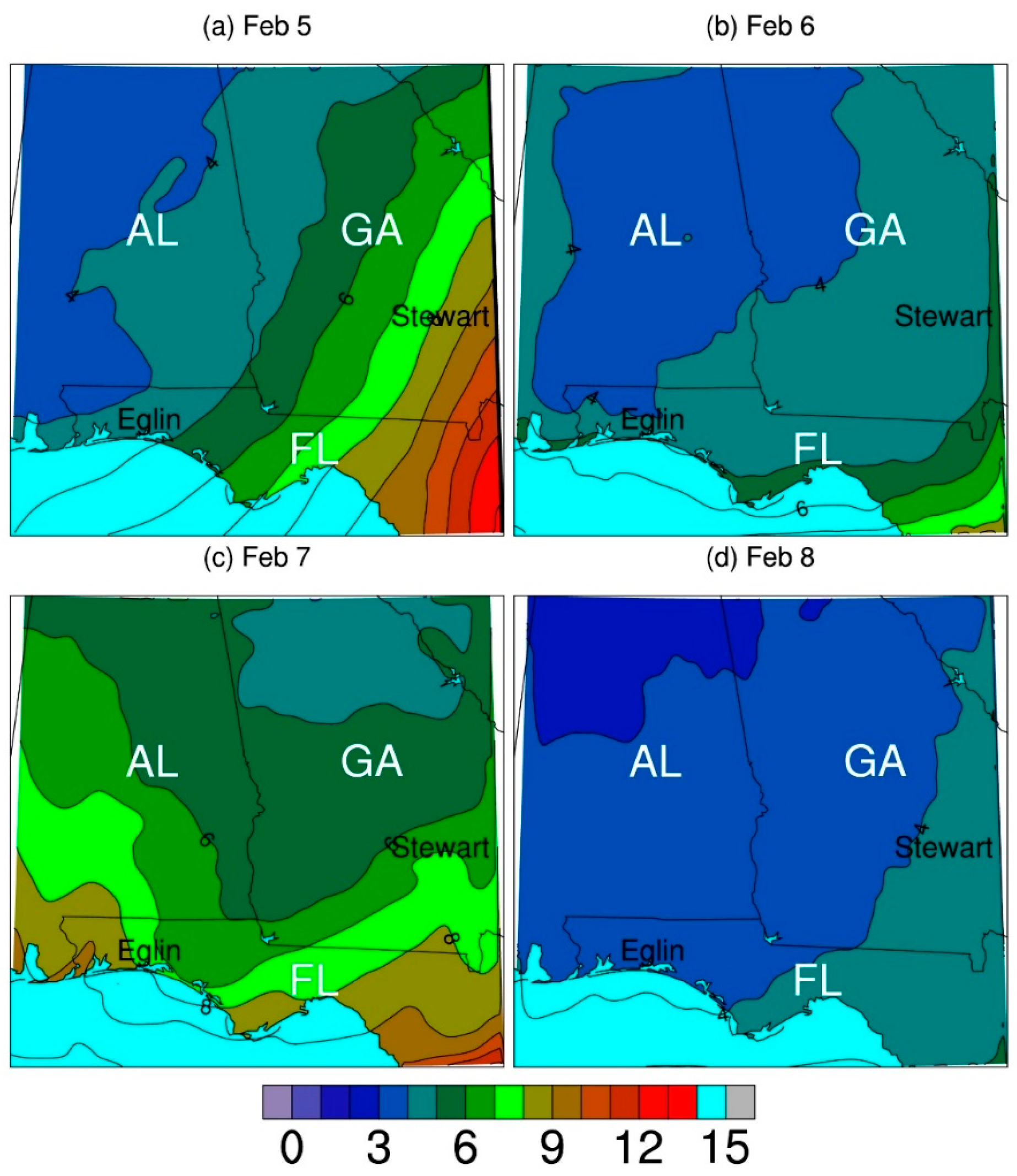
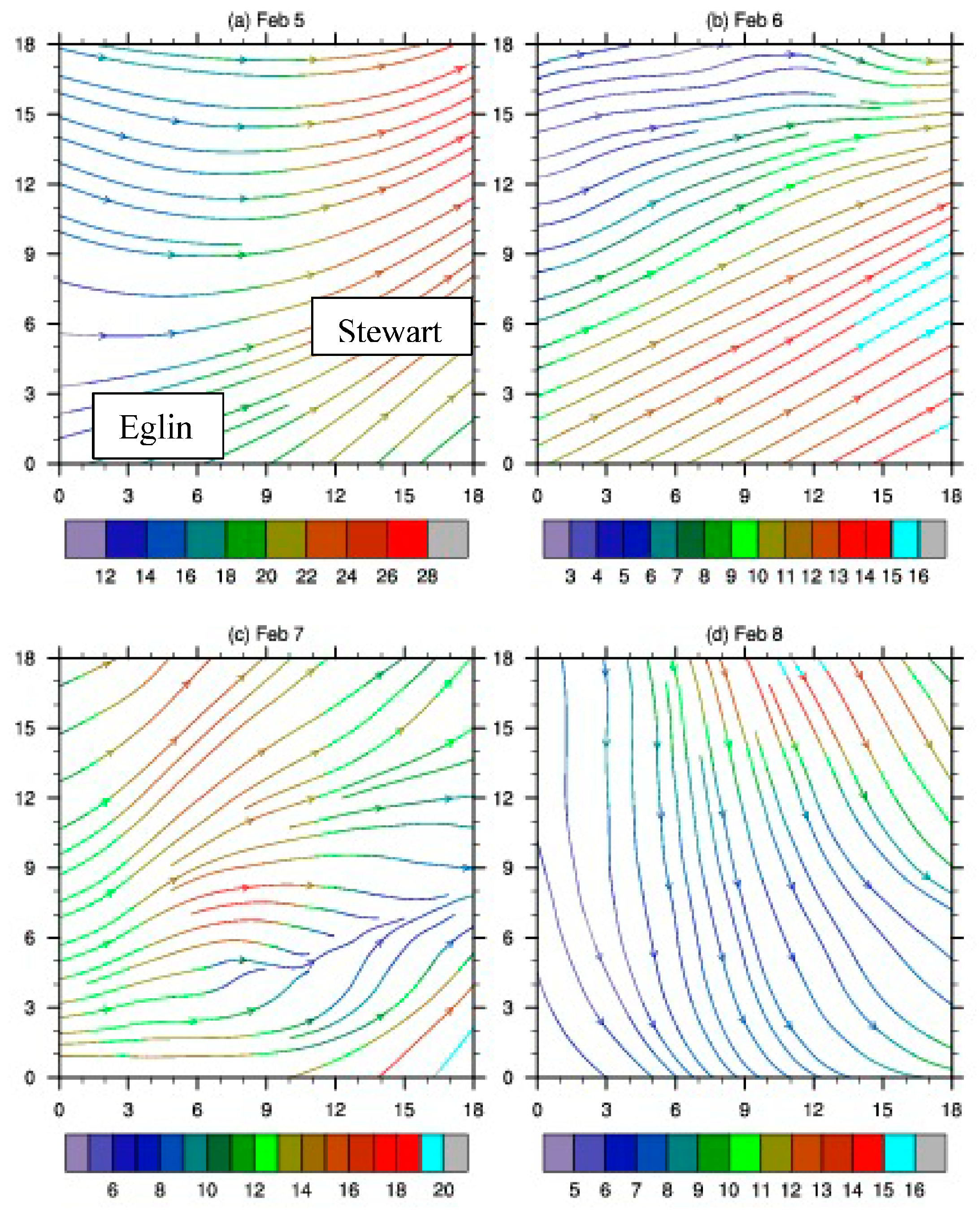
On 5 February, the surface temperature, which is about the same as potential temperature on the ground, simulated with WRF increases from about 3 °C in northwestern Alabama (AL) to about 20 °C in southeastern Georgia (GA) and northeastern Florida (FL) (Figure 1a). The simulated surface specific humidity shows the same spatial distribution, increasing from about 3 to 15 g/kg (Figure 2a). The simulated gradient is the largest for both fields near the GA-FL border. Westerly winds prevail at about 850 hPa (1.5 km) elevation (Figure 3a). Winds change from slightly northwesterly at about 15 m/s in northern AL to southwesterly at about 25 m/s in northern GA. The weather pattern on this day is characterized by a cold front oriented from southwest to northeast near the GA-FL border on the ground, as indicated by the noticeable changes from the northwest to southeast of the simulation domain in surface temperature and humidity, and a shallow trough in northern AL and GA at 850 hPa. As shown below, the spatial changes are much smaller on the other three days with the cold front moving out of this region. On February 6th, the temperature increases in northwestern AL but slightly decreases in southeastern GA and northern FL (Figure 1b). The specific humidity is reduced remarkably in southeastern GA and northern FL (Figure 2b). Thus, both the temperature and humidity gradients are reduced. The westerly winds at 850 hPa remain, but the direction is now from southwesterly in northern AL to northwesterly in northern GA (Figure 3b). The spatial distributions of the weather elements indicate the cold front on 5 February moved out of the simulation domain and the shallow trough is replaced by a weak ridge.
On 7 February, the temperature decreases slightly from 6 February (Figure 1c), but the specific humidity increases (Figure 2c). The winds are southwesterly (Figure 3c). All these changes indicate that the simulation domain is located in the eastern section of another trough system with a trough line located west to the domain. On 8 February, the temperature reduces slightly again (Figure 1d), and the specific humidity decreases dramatically (Figure 2d). The winds are northerly (Figure 3d). The domain is located behind the trough line.
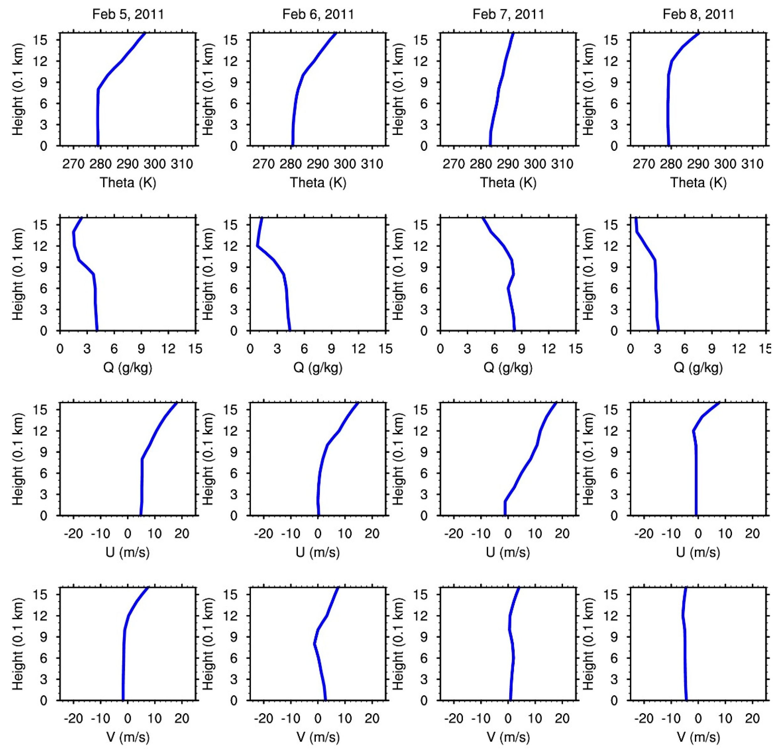
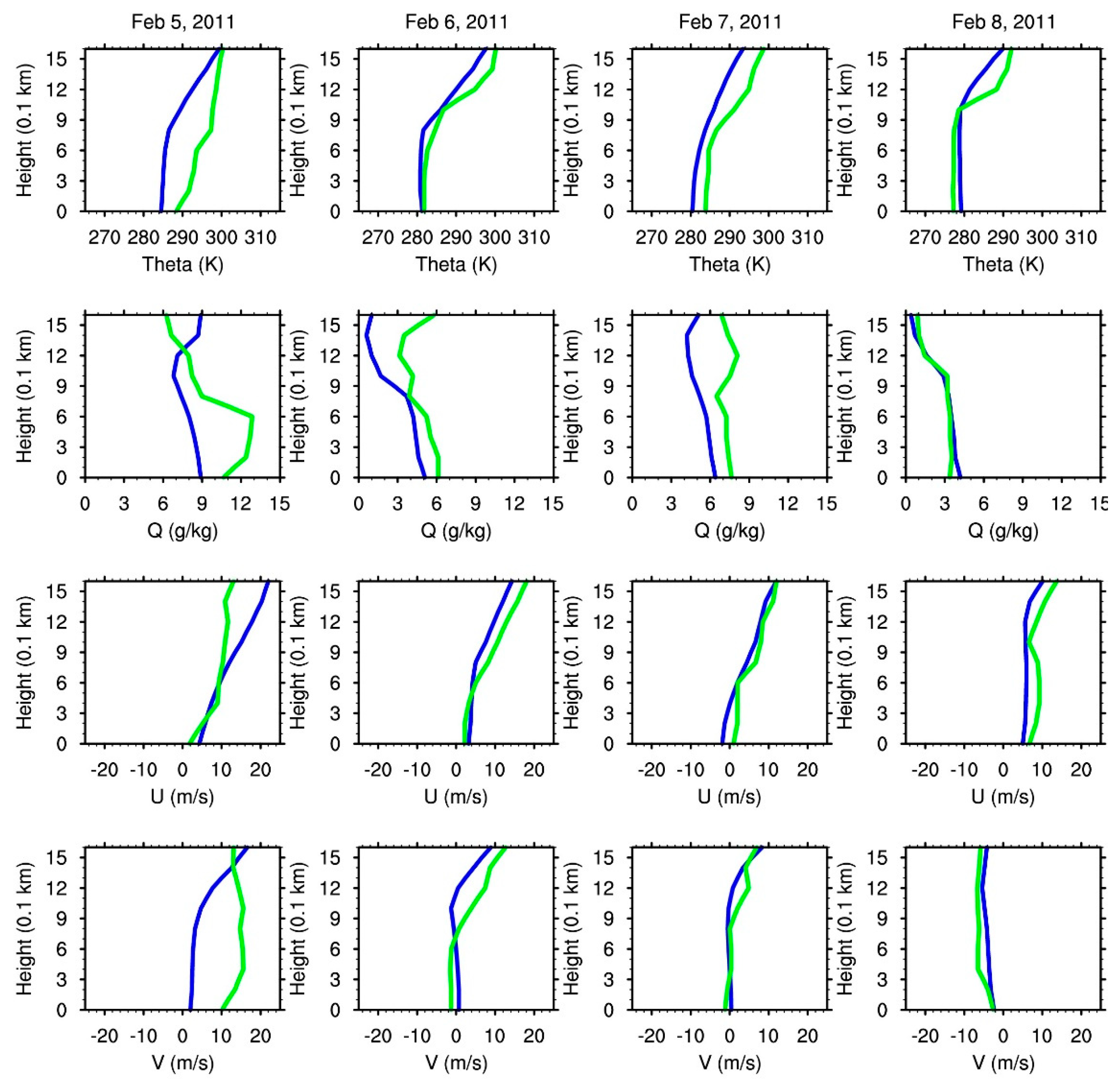
Thus, a weak trough and a strong trough move though the domain on the first and last day of the simulation period, respectively, with a weak ridge in between the two days. Weather at Eglin has little changes from 6 to 8 February except a shift of surface winds from weak southwesterly to large northerly (Figure 4). In contrast, weather at Stewart changes remarkably from warm and moist to cool and dry conditions throughout the 4-day period (Figure 5). The simulated vertical profiles of potential temperature and wind components are in agreement with the observed profiles in Jacksonville, FL on 5 thru 8 February. On 4 February, however, the simulated potential temperature, humidity, and the south to north component wind speed are too low. The difference is created by the distance between the two sites within the cold front system. Fort Stewart is very close to the frontline, while Jacksonville is in the warm side of the front where the air is warmer and moister with winds coming mostly from the south. The simulated humidity is also smaller in comparison with the observation on 5 and 6 February but comparable to the observation on 8 February.

3.2. Evaluation of Daysmoke Simulations at Eglin

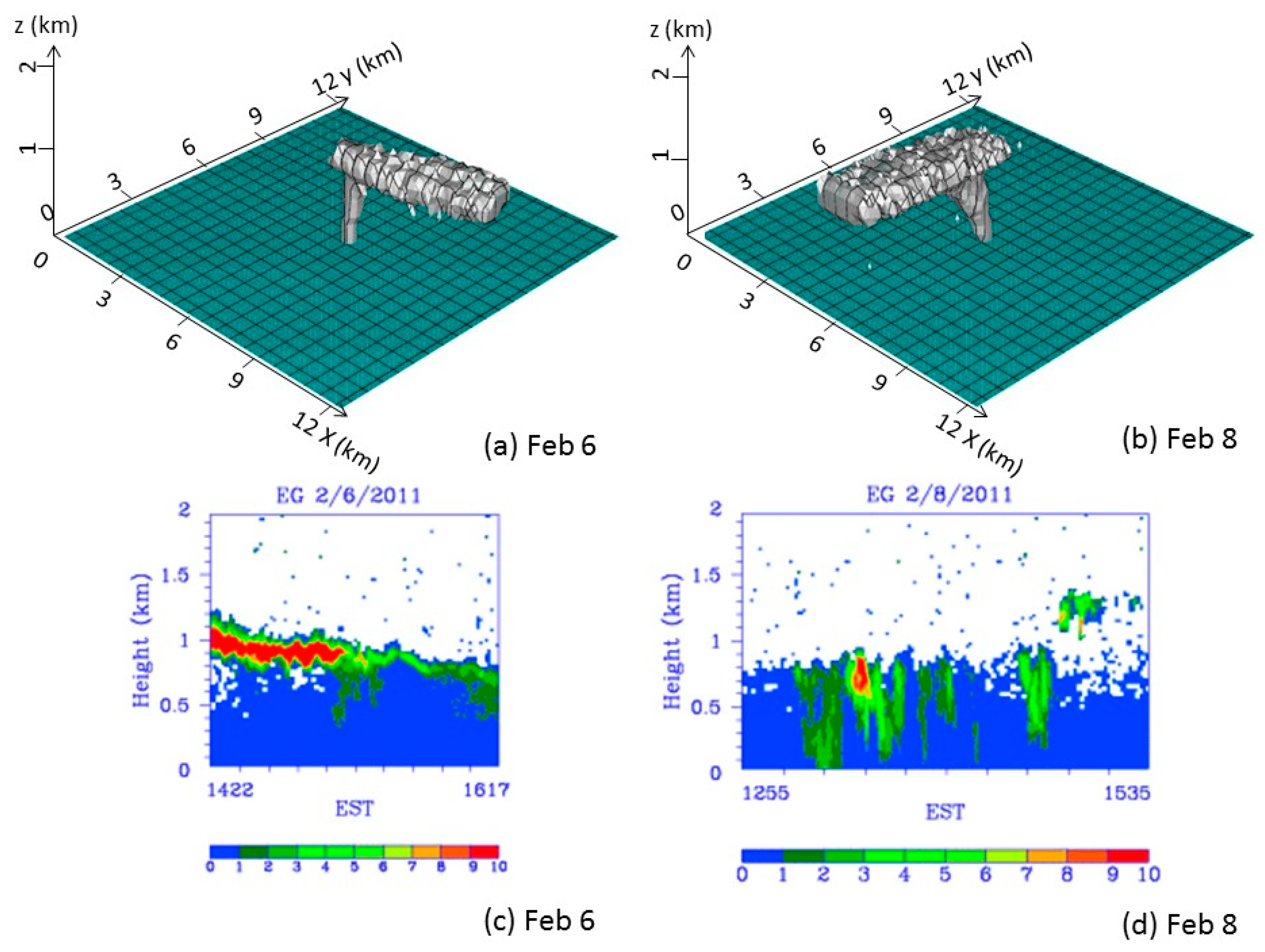
The Daysmoke simulation of a prescribed burn at Eglin on 6 February (Figure 6) shows a smoke plume that first rises locally and then moves eastward. The plume height is about 1.25 km. The model produces a similar plume on 8 February, but the plume moves southward with a lower plume height of about 0.95 km. In comparison, the measured smoke plume on 6 February shows a well-developed smoke plume with a height at about 1.2 km at the beginning and slowly decreases with time. The photos as well as visual views at the burn site showed eastward smoke movement. The measured plume on 8 February shows fluctuations with time. The measured plume height was about 0.9 km (the signals above 1.2 km after 1500 EST were from clouds). A southward movement of the smoke plume was seen at the scene. Thus, the simulated plume rise and transport direction are comparable to those of the measurements. However, the model does not reproduce the measured smoke fluctuation structure on 8 February. Also note that smoke plume rise simulated with Daysmoke decreases slightly with an increasing number of updrafts [19], which are physically separated sub-smoke plumes on the ground. Some models such as WRF-SFIRE-CHEM [12] simulate multiple updrafts, but Daysmoke uses a specified number of updrafts. The updraft number used in the simulations is 4, obtained from smoke photos at the burn site [24].
The potential temperature simulated with WRF increases very slowly within about the first 1 km on 6 February but rapidly thereafter (Figure 4). These changes suggest that the simulated PBL height (the height where potential temperature begins to increase rapidly) is about 1.0 km. The potential temperature on 8 February is unchanged until about 1.1 km. The difference between the two days indicates a more stable boundary layer on February 6th which contributes to the formation of a smoke cap. It seems that the plume rises above and below the PBL height on these two days, respectively.
The simulated winds on 6 February are weak on the ground in both west-east and south-north directions, but westerly winds increase rapidly with height, which contributes to the eastward smoke movement. The simulated winds on 8 February are from the north, which contributes to the southward smoke movement and the measured temporary fluctuations.

3.3. Daysmoke Simulation of Prescribed Burning at Stewart

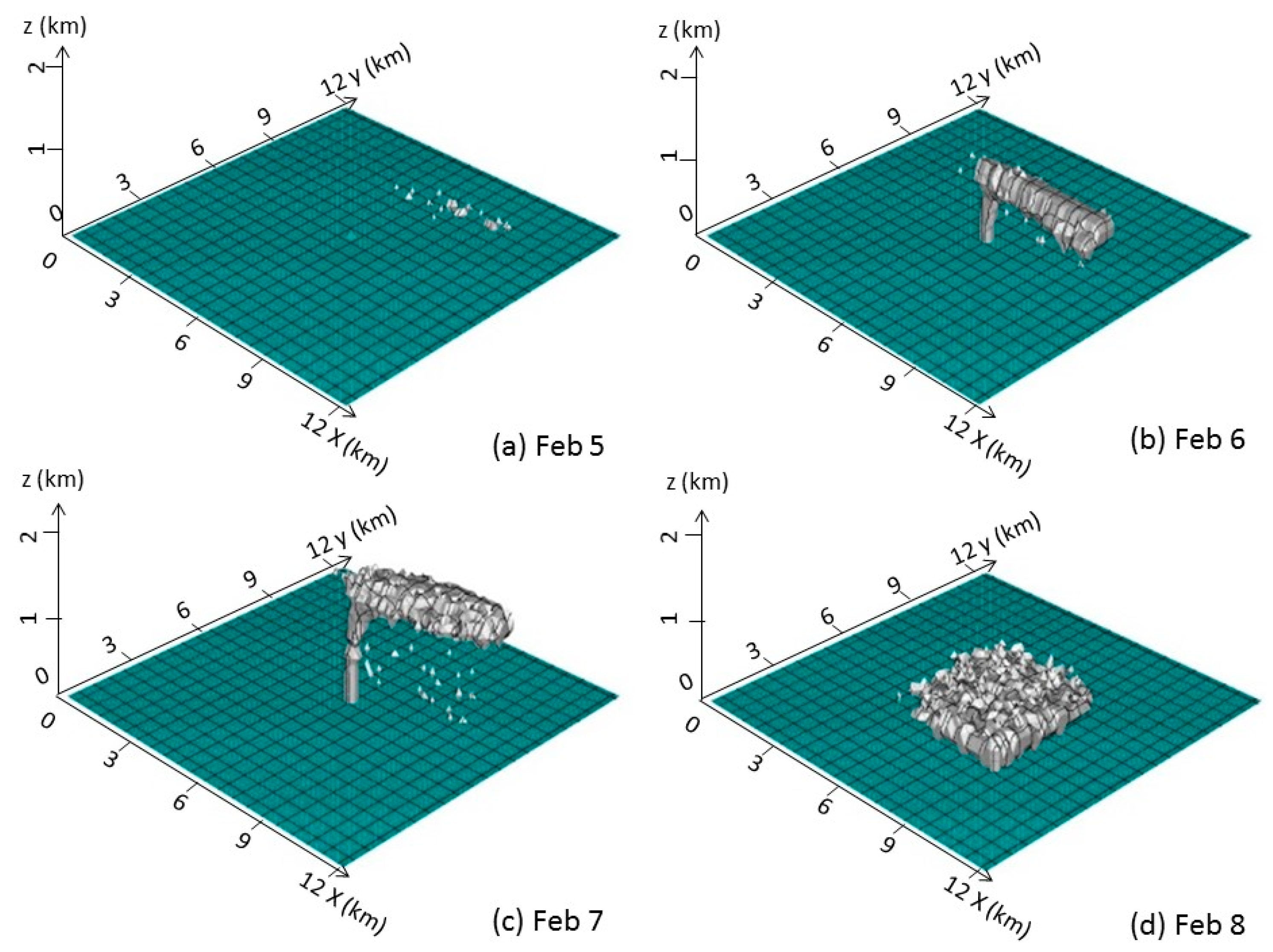
The simulated smoke does not form a typical plume on 5 February (Figure 7a). The smoke moves eastward. This situation changes noticeably on February 6th when a well-developed plume is formed (Figure 7b). Smoke also moves eastward. This form of plume remains the same the next day except larger height (Figure 7c). The simulated plume on 8 February is totally different from those in the previous two days. The smoke rises lower, disperses widely in horizontal directions, and moves southeasterly (Figure 7d). The plume heights on 5 thru 8th February with 4 updraft cores are about 1.0, 1.1, 1.5, and 1.2 km, respectively.
The warm, moist, and windy weather on 5 February reduces smoke plume height in general. The warm surface means dry fuels and therefore large heat release. However, the stable PBL depresses plume development. The moist condition means wet fuels and therefore decreases fuel combustion and heat release. The large winds, especially in the upper PBL, make the smoke bend horizontally instead of ascend vertically. On February 6th, the weather becomes cooler with surface air temperature reduced by about 4 K and drier with surface specific humidity reduced from about 9 to 5 g/kg, which decreases and increases smoke plume height, respectively. Meanwhile, the ambient is calmer with the u and v wind components reduced by 2~5 m/s throughout the PBL, which favors smoke plume development. The well-developed smoke plume on this day indicates the dominant roles of wind and humidity. On 7 February, potential temperature and v wind components change little; specific humidity increases by about 1.5 g/kg but u wind component decreases by about 1~3 m/s throughout the PBL, which decreases and increases smoke plume height, respectively. The fact that smoke plume rises higher than the previous day indicates that the wind is a more important factor than humidity. The weather on 8 February is the coldest and driest among the four days and as windy as 5 February. The dry fuels lead to large emissions but the windy condition leads to the development of irregular smoke plume and low plume rise.

3.4. PB-P Simulations of Prescribed Burning at Stewart

The simulated winds at 1700 LST on 5 February blow from the west (Figure 8a). Red dots at midnight (Figure 8b) indicate that PB-P has identified possible conditions of collocation of smoke and fog. By 0400 LST (Figure 8c), fog conditions are lifted. No changes in plume structure are noted at 0700 LST (Figure 8d).
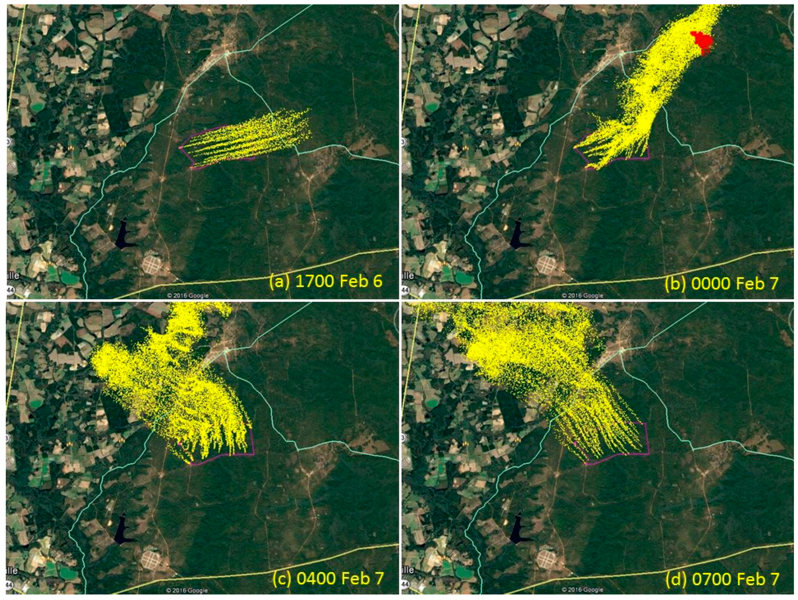
The simulated winds blow from the west as shown by the 1700 LST on 6 February (Figure 9a). By midnight (Figure 9b) the winds shift to blow from the southwest. Winds diminish and shift to blow from the southeast by 0400 LST, 7 February (Figure 9c). Relative humidity is below the model threshold to warn of the potential of a smoke/fog mixture. Smoke drainage can be seen on the right side of the plume. By 0700 LST (Figure 9d), southeasterly winds strengthen.
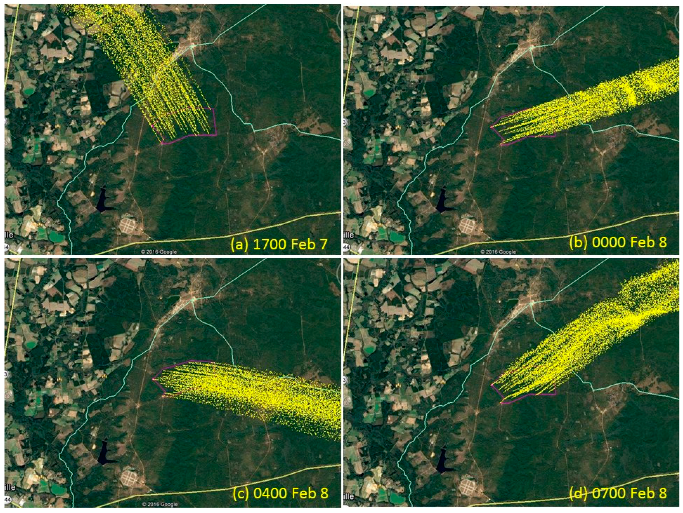
The southeasterly winds continue at 1700 LST on 7 February (Figure 10a). The wind direction slowly shifts by midnight (Figure 10b), blowing strongly from the southwest as indicated by the lack of spread in the plume. By 0400 LST, 8 February, the winds are blowing from the west-northwest (Figure 10c). The southwesterly winds return by 0700 LST (Figure 10d). There is no indication of fog during this night nor is there an indication of plume capture by local drainages.
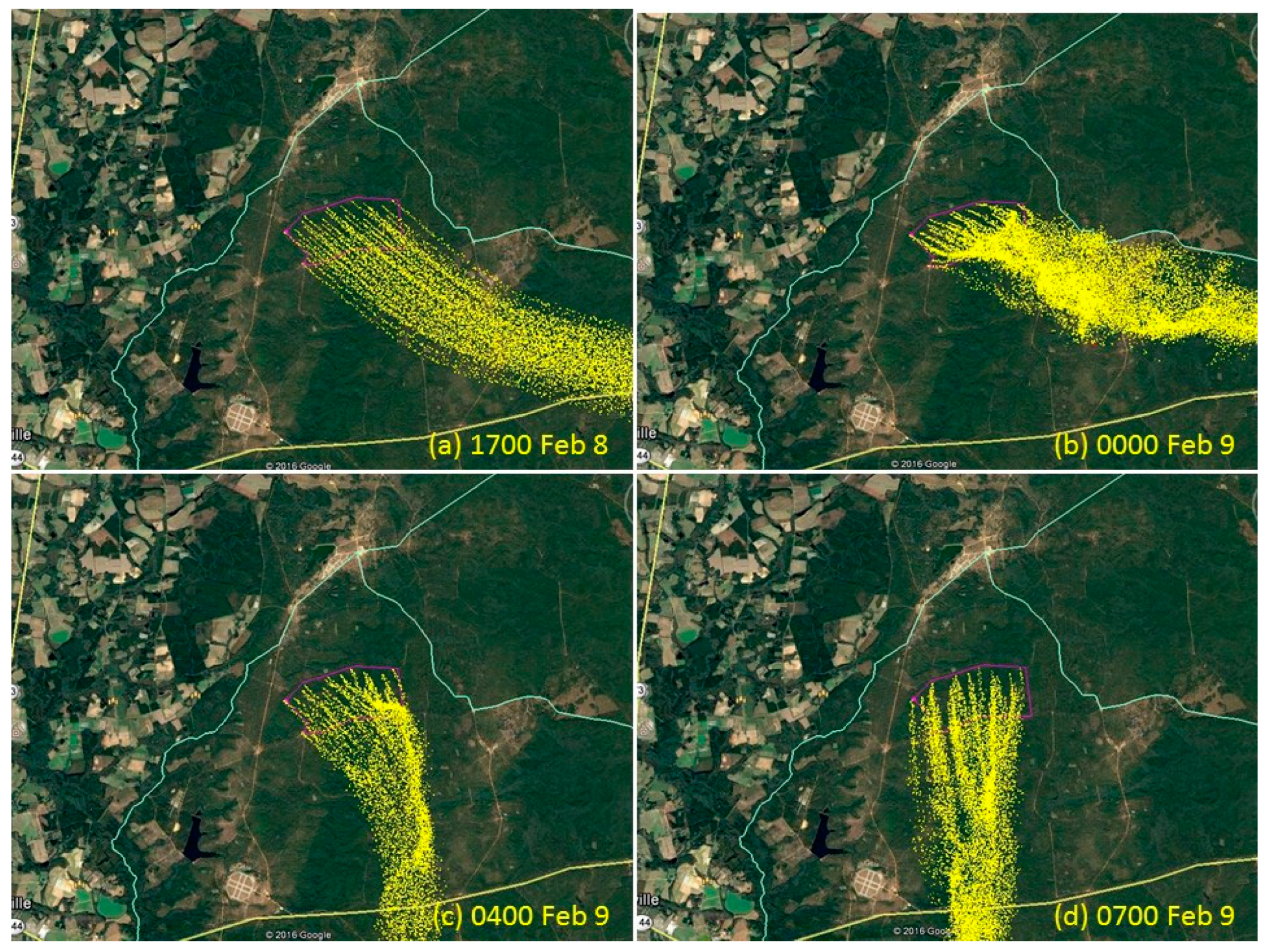
The winds blow from the northwest at 1700 LST, 8 February (Figure 11a). By midnight (Figure 11b), the winds are still blowing from the northwest albeit with reduced speeds. The plume is distorted by the surrounding terrain; however, there is no indication of drainage flow entrapment. The winds have shifted to blow from the north by 0400 LST, 9 February (Figure 11c). There is some evidence for valley steering of the plume as suggested by the bright band of particles. The winds continue blowing from the north for the remainder of the night (Figure 11d). The plume of particles near the ground blows across highway SR-144. Conditions never become favorable for collocation of fog.
The PB-P simulations show the occurrence of nighttime drainage and super-fog, potentially impacting local visibility and traffic. The local wind field can transport smoke near the ground to distant locations—some near or within urban areas and others across roadways some distance from the locations of the burns. The atmosphere in southeastern United States is often moist favoring formation of super-fog. The fog can affect traffic on roads that are often close to residential areas.
The fundamental assumption behind PB-P is that smoldering combustion takes place at randomly located places within the area burned throughout the night following the burn. In some cases, fuels are consumed quickly and there is little or no smoldering in the aftermath of the burn. Thus predictions from PB-P in these cases would not be valid. This needs to be considered when planning FASMEE measurements of nighttime smoke. Also, currently Daysmoke and PB-P are two separate models. Accordingly, the flaming and smoldering phases of the burns for the two models are separate smoke events.

4. Conclusions

Simulations have been conducted with Daysmoke and PB-P for prescribed burns in the southeastern United States. The results show large variability for the hypothetical prescribed burns at Stewart over a period of 4 days. Well-developed smoke plumes are found on two out of these days. Plume height changes from about 1.1 km on one day to 1.5 km next day. Nighttime smoke drainage and super-fog are formed on one night but not on another night. Wind is probably the most important single meteorological element for plume form and height. Thus, weather conditions on the FASMEE experimental burn days at Stewart are critical for obtaining desired smoke plumes for field measurements and could vary on a daily basis.
The simulations at Stewart provided useful information on the weather systems that would produce the desired smoke plumes with clearly defined boundaries during daytime and smoke drainage and super-fog during nighttime for the FASMEE field campaign and the major contributing meteorological elements. One ideal weather condition for the daytime smoke plumes would be a period between two low-pressure systems, and the condition for the nighttime smoke induced fog would be the warm and moist section of a low-pressure system and a front surrounding the burn site.

Author Contributions

Y.L., S.G., and G.A. worked on a project that led to this research paper. Y.L. conducted Daysmoke simulations and drafted the manuscript. G.A. conducted PB-P simulations and prepared description of the results.

Funding

Joint Fire Science Program (JFSP) under agreement JFSP16-4-05-2.

Acknowledgments

The authors wish to thank the reviewers for very constructive and insightful comments and detailed editorial suggestions. We also would like to thank the FASMEE leadership team for directing the FASMEE (Phase I) project and Shela Mou for English editing. This study was supported by the Joint Fire Science Program (JFSP) under agreement JFSP16-4-05-2.

Conflicts of Interest

The authors declare no conflicts of interest.

References

  1. Goodrick, S.A.; Achtemeier, G.L.; Larkin, N.K.; Liu, Y.-Q.; Strand, T.M. Modelling smoke transport from wildland fires: A review. Int. J. Wildl. Fire 2012, 22, 83–94. [Google Scholar] [CrossRef]
  2. Lavdas, L.G. Program VSMOKE—Users Manual; USDA Forest Service, Southeastern Forest Experiment Station, General Technical Report SRS-6. (Macon GA); US Department of Agriculture, Forest Service, Southern Research Station: Asheville, NC, USA, 1996.
  3. Sestak, M.L.; Riebau, A.R. SASEM, Simple Approach Smoke Estimation Model; Technical Note 382; US Bureau of Land Management: Denver, CO, USA, 1988.
  4. Mell, W.; Jenkins, M.A.; Gould, J.; Cheney, P. A physics-based approach to modeling grassland fires. Int. J. Wildl. Fire 2007, 16, 1–22. [Google Scholar] [CrossRef]
  5. Achtemeier, G.L.; Goodrick, S.A.; Liu, Y.-Q.; Garcia-Menendez, F.; Hu, Y.; Odman, M.T. Modeling smoke plume-rise and dispersion from southern United States prescribed burns with Daysmoke. Atmosphere 2011, 2, 358–388. [Google Scholar] [CrossRef]
  6. Achtemeier, G.L. Planned Burn—Piedmont. A local operational numerical meteorological model for tracking smoke on the ground at night: Model development and sensitivity tests. Int. J. Wildl. Fire 2005, 14, 85–98. [Google Scholar] [CrossRef]
  7. Appel, K.W.; Napelenok, S.L.; Foley, K.M.; Pye, H.O.; Hogrefe, C.; Luecken, D.J.; Bash, J.O.; Roselle, S.J.; Pleim, J.E.; Foroutan, H.; et al. Description and evaluation of the Community Multiscale Air Quality (CMAQ) modeling system version 5.1. Geosci. Model Dev. 2017, 10, 1703–1732. [Google Scholar] [CrossRef]
  8. Scire, J.S. CALPUFF: Overview of capabilities. In Proceedings of the Technical Highlights of EPA’s 7th Conference on Air Pollution Modeling, Raleigh, NC, USA, 1 August 2000; Available online: www.epa.gov/scram001/7thconf/information/t029day1.pdf (accessed on 11 July 2018).
  9. Draxler, R.R.; Rolph, C.D. HYSPLIT (HYbrid Single-Particle Lagrangian Integrated Trajectory) Model Access via NOAA ARL READY Website; NOAA Air Resources Laboratory: Silver Spring, MD, USA, 2003. Available online: http://www.arl.noaa.gov/ready/hysplit4.html (accessed on 11 July 2018).
  10. Larkin, N.K.; O’Neill, S.M.; Solomon, R.; Raffuse, S.; Strand, T.; Sullivan, D.C.; Ferguson, S.A. The BlueSky Smoke Modeling Framework. Int. J. Wildl. Fire 2010, 18, 906–920. [Google Scholar] [CrossRef]
  11. Mandel, J.; Beezley, J.D.; Kochanski, A.K. Coupled atmosphere-wildland fire modeling with WRF 3.3 and SFIRE. Geosci. Model Dev. 2011, 4, 591–610. [Google Scholar] [CrossRef] [Green Version]
  12. Kochanski, A.K.; Jenkins, M.A.; Yedinak, K.; Mandel, J.; Beezley, J.; Lamb, B. Toward an integrated system for fire, smoke, and air quality simulations. Int. J. Wildl. Fire 2015, 25, 558–568. [Google Scholar] [CrossRef]
  13. Liu, Y.-Q.; Kochanski, A.; Baker, K.; Mell, R.; Linn, R.; Paugam, R.; Mandel, J.; Fournier, A.; Jenkins, M.A.; Goodrick, S.; et al. Fire behavior and smoke modeling: Model improvement and measurement needs for next-generation operational smoke prediction systems. Int. J. Wildl. Fire 2018. to be submitted. [Google Scholar]
  14. Briggs, G.A. Plume Rise Predictions. In Lectures on Air Pollution and Environmental Impact Analyses; American Meteorological Society: Boston, MA, USA, 1975; pp. 72–73. [Google Scholar]
  15. Achtemeier, G.L.; Goodrick, S.A.; Liu, Y.-Q. Modeling Multiple-Core Updraft Plume Rise for an Aerial Ignition Prescribed Burn by Coupling Daysmoke with a Cellular Automata Fire Model. Atmosphere 2012, 3, 352–376. [Google Scholar] [CrossRef] [Green Version]
  16. Ottmar, R.; Brown, T.J.; French, N.H.F.; Larkin, N.K. Fire and Smoke Model Evaluation Experiment (FASMEE) Study Plan, Joint Fire Science Program Project #15-S-01-01. 2017. Available online: https://www.fasmee.net/study-plan/ (accessed on 11 July 2018).
  17. Prichard, S.J.; Sandberg, D.V.; Ottmar, R.D.; Campbell, P.W. FCCS User’s Guide (Version 2.0). 2015. Available online: https://www.researchgate.net/publication/254495982_FCCS_User’s_Guide_Version_20 (accessed on 11 July 2018).
  18. Anderson, G.K.; Sandberg, D.V.; Norheim, R.A. Fire Emission Production Simulator (FEPS) User’s Guide (Version 1.0). 2004. Available online: https://www.fs.fed.us/pnw/fera/feps/FEPS_users_guide.pdf (accessed on 11 July 2018).
  19. Liu, Y.-Q.; Goodrick, S.; Achtemeier, G.; Jackson, W.A.; Qu, J.J.; Wang, W. Smoke incursions into urban areas: Simulation of a Georgia prescribed burn. Int. J. Wildl. Fire 2009 18, 336–348. [CrossRef]
  20. Liu, Y.-Q.; Achtemeier, G.; Goodrick, S.; Jackson, W.A. Important parameters for smoke plume rise simulation with Daysmoke. Atmos. Pollut. Res. 2010, 1, 250–259. [Google Scholar] [CrossRef] [Green Version]
  21. Linn, R.R.; Reisner, J.; Colmann, J.J.; Winterkamp, J. Studying wildfire behavior using FIRETEC. Int. J. Wildl. Fire 2002, 11, 233–246. [Google Scholar] [CrossRef] [Green Version]
  22. Powers, J.G.; Klemp, J.B.; Skamarock, W.C.; Davis, C.A.; Dudhia, J.; Gill, D.O.; Coen, J.L.; Gochis, D.J. The Weather Research and Forecasting Model: Overview, System Efforts, and Future Directions. Bull. Am. Meteorol. Sci. 2017, 98, 1717–1737. [Google Scholar] [CrossRef]
  23. Mesinger, F.; DiMego, G.; Kalnay, E.; Mitchell, K.; Shafran, P.C.; Ebisuzaki, W.; Jović, D.; Woollen, J.; Rogers, E.; Berbery, E.H.; et al. North American Regional Reanalysis. Bull. Am. Meteorol. Soc. 2006, 87, 343–360. [Google Scholar] [CrossRef] [Green Version]
  24. Liu, Y.-Q.; Goodrick, S.; Achtemeier, G.; Forbus, K.; Combs, D. Smoke plume height measurement of prescribed burns in the south-eastern United States. Int. J. Wildl. Fire 2012, 22, 130–147. [Google Scholar] [CrossRef]
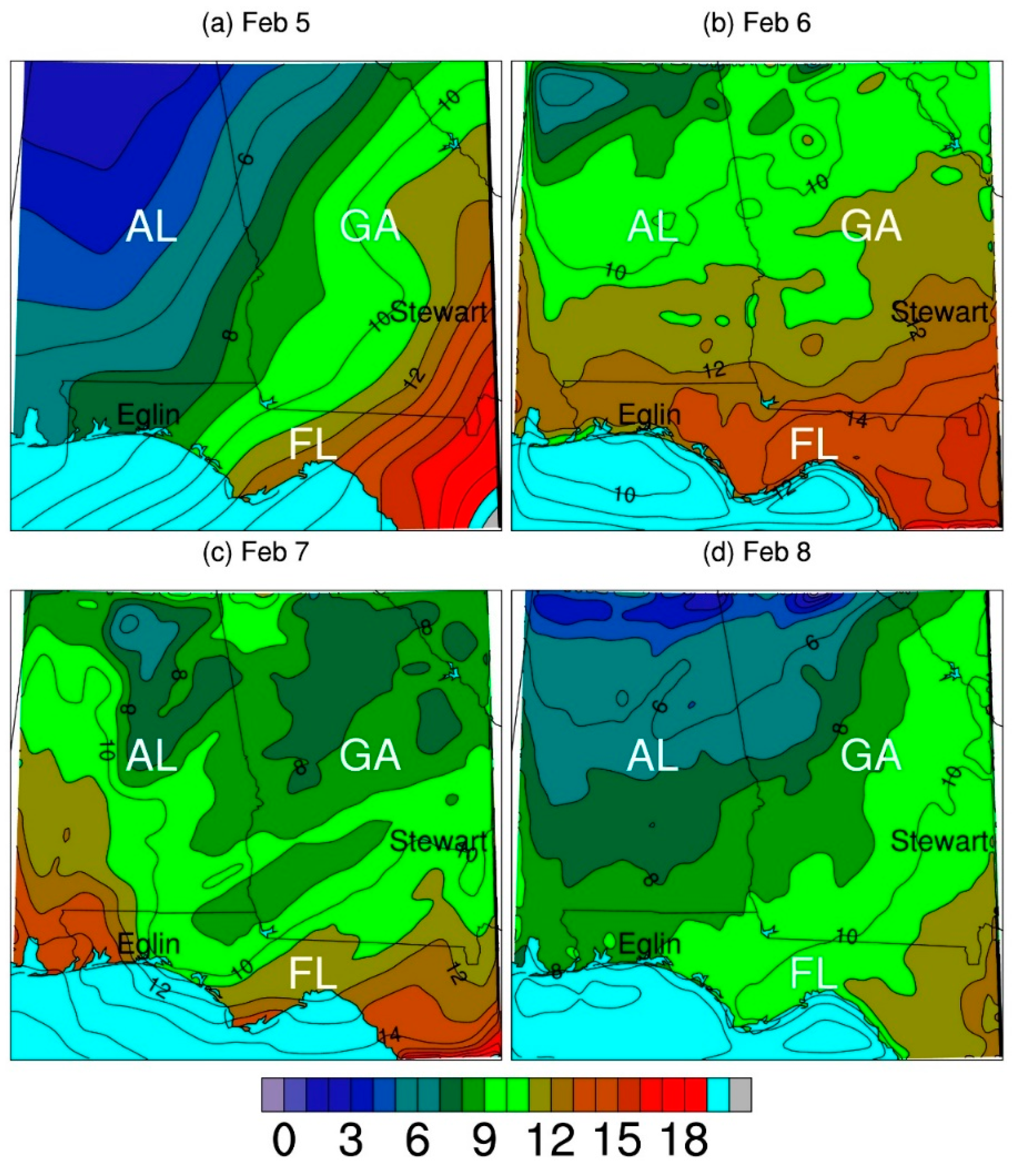
Figure 1. Surface temperature (°C) simulated with WRF. (ad) are 5–8 February 2011 at noon local time. GA, FL, and AL stand for Georgia, Florida and Alabama. Stewart and Eglin are hypothetical FASMEE burn site and historical burn site, respectively.
Atmosphere 09 00259 g001
Figure 2. Surface specific humidity (g/kg) simulated with WRF. (ad) are 5–8 February 2011 at noon local time. GA, FL, and AL stand for Georgia, Florida and Alabama. Stewart and Eglin are hypothetical FASMEE burn site and historical burn site, respectively.
Atmosphere 09 00259 g002
Figure 3. Streamlines and wind speed (m/s) at 850 hPa simulated with WRF. (ad) are 5–8 February 2011 at noon local time. Wind speed is indicated by color.
Atmosphere 09 00259 g003
Figure 4. Vertical profiles of potential temperature (K) (top), specific humidity (g/kg) (second row), westerly and southerly wind components (m/s) (third and fourth rows) at Eglin simulated with WRF. The columns from left to right are 5–8 February 2011 at noon local time.
Atmosphere 09 00259 g004
Figure 5. Vertical profiles of potential temperature (K) (top), specific humidity (g/kg) (second row), westerly and southerly wind components (m/s) (third and fourth rows) at Fort Stewart simulated with WRF (blue) and Jacksonville, FL observed from radiosonde (green). The columns from left to right are 5–8 February 2011 at noon local time.
Atmosphere 09 00259 g005
Figure 6. Smoke plumes at Eglin on 6 and 8 February at 1400 local time. (a,b) are Daysmoke simulations. (c,d) are the corresponding ceilometer detections with the horizontal axis indicating local time (from [24]).
Atmosphere 09 00259 g006
Figure 7. Smoke plumes at Stewart on 5–8 February at 1200 local time (ad) simulated with Daysmoke. The burn site is located at the center grid cell.
Atmosphere 09 00259 g007
Figure 8. PB-P simulation of smoke during night of 5 February 2011 at four times (ad). Yellow indicates smoke particles. Red indicates formation of fog. The blue/pink area is the hypothetical burn site of Block 3.
Atmosphere 09 00259 g008
Figure 9. PB-P simulation of smoke during night of 6 February 2011 at four times (ad). Yellow indicates smoke particles. Red indicates formation of fog. The pink area is the hypothetical burn site of Block 3.
Atmosphere 09 00259 g009
Figure 10. PB-P simulation of smoke during night of 7 February 2011 at four times (ad). Yellow indicates smoke particles. The pink area is the hypothetical burn site of Block 3.
Atmosphere 09 00259 g010
Figure 11. PB-P simulation of smoke during night of 8 February 2011 at four times (ad). Yellow indicates smoke particles. The pink area is the hypothetical burn site of Block 3.
Atmosphere 09 00259 g011
Table 1. Physical schemes used in the WRF simulations.
Physical ProcessSchemeProperty
Short-wave radiationDudhia schemeSimple downward integration allowing efficiently for clouds and clear-sky absorption and scattering
Long-wave radiationRapid Radiative Transfer ModelAn accurate scheme using look-up tables for efficiency. Accounts for multiple bands, and microphysics species.
ConvectionKain-Fritsch schemeDeep and shallow convection sub-grid scheme using a mass flux approach with downdrafts and CAPE removal time scale
PBLYonsei University schemeNon-local-K scheme with explicit entrainment layer and parabolic K profile in unstable mixed layer
Surface layerMM5 similarityBased on Monin-Obukhov with Carslon-Boland viscous sub-layer and standard similarity functions from look-up tables
Land surfaceThermal diffusionSoil temperature only scheme. Five layers.