Article

Effect of Multiple Injection Strategy Under High Ammonia Ratio on Combustion and Emissions of Liquid Ammonia/Diesel Dual DI Engine

Mechanical and Electrical Engineering College, Hainan University, Haikou 570228, China
*
Author to whom correspondence should be addressed.
Atmosphere 2025, 16(1), 94; https://doi.org/10.3390/atmos16010094
Submission received: 4 December 2024 / Revised: 23 December 2024 / Accepted: 14 January 2025 / Published: 16 January 2025
(This article belongs to the Special Issue Renewable Strategies for Emission Reduction: A Multisectoral Approach)

Abstract

:
With the increasingly prominent environmental and energy issues, emission regulations are becoming more stringent. Ammonia diesel dual fuel (ADDF) engine is one of the effective ways to reduce carbon emissions. This study investigated the effect of multiple injection strategy on the combustion and emission characteristics of liquid ammonia/diesel dual direct injection (DI) engines through numerical simulation. The results showed that under the condition of maintaining the same pre injection diesel fuel and high ammonia energy ratio (80%), with the introduction of multiple injection, the peak cylinder pressure decreased and the peak phase advanced, the combustion start angle (CA10) advanced, the heat release showed a multi-stage pattern. The times of injection (TSOI) has a significant effect on combustion and emissions. As TSOI increased, ignition delay decreased, the combustion duration is shortened, and the combustion is accelerated. Notably, overall emissions of NOx and N2O have decreased, but the emissions of unburned NH3 have increased. Optimized the state of ammonia injection (SOAI) timing and ammonia injection pressure (AIP), showed that advancing SOAI timing and increasing AIP improved combustion. Advanced the SOAI timing to −8 °CA ATDC, resulted in a significant NOx emissions decrease with an increase in TSOI, reaching over 50%. Although increasing injection pressure can improve combustion, it also results in higher N2O emissions.

1. Introduction

In the contemporary era, the finite nature of fossil fuels has driven the need to address energy shortages, spurring innovations in engine technology and the exploration of alternative fuels [1]. In response to global environmental challenges such as the greenhouse effect, the International Maritime Organization has convened the 80th Meeting of the Marine Environmental Protection Committee with the goal of achieving net zero greenhouse gas (GHG) emissions from international shipping by 2050 [2]. At the same time, China has introduced strategies for carbon peaking and neutrality [3]. One of the most effective approaches to reducing emissions is replacing fossil fuels with low-carbon or zero-carbon alternatives. In recent years, the use of zero carbon or low-carbon fuels in internal combustion engines provides enormous potential for reducing carbon emissions [4,5,6]. Ammonia (NH3) is a zero carbon fuel that easily liquefies at low pressure (around 1 MPa) at room temperature, making storage simpler [7]. Additionally, it has safety advantages over hydrogen, including a lower risk of explosion and a distinct odor that aids in leak detection [8]. However, ammonia’s application in engines faces challenges due to its poor ignition characteristics, such as high auto-ignition temperature, low calorific value, and slow flame propagation speed. These factors make it difficult to use ammonia alone in compression ignition (CI) engines to achieve efficient combustion [8,9]. To overcome these limitations, researchers have explored using highly reactive fuels as combustion aids in ammonia-powered engines [10].
Ammonia-diesel dual-fuel (ADDF) engines have gained attention for their potential to reduce emissions. Shin et al. [11] explored the combustion characteristics of ammonia-diesel DI engines, discovering a reduction in NO emissions by 13.5% and GHG emissions by approximately 91% when compared to engines operating solely on diesel. Niki et al. [12] maintained an ammonia energy ratio (AER) of 15% in their study, investigating the emissions of unburned ammonia and nitrous oxide (N2O) by altering the diesel injection strategy. Their findings indicated that while pre-injection of diesel mitigates the release of unburned ammonia, it concurrently elevated emissions of nitrogen oxides (NOx), carbon monoxide (CO), and N2O.
ADDF engines typically fall into two categories: those injecting gaseous ammonia into the intake manifold and those using direct in-cylinder injection of liquid ammonia [13,14,15,16]. Liu et al. [17] conducted an experimental investigation into an ADDF system, confirming that the ignition process of diesel in an ammonia-air mixture is extended, enhancing premixed combustion. However, a higher ammonia substitution rate reduced the proportion of mix-controlled combustion, diminishing the diesel flame propagation area. Ammonia oxidation predominantly occurred near the diesel flame, and the overly dilute ammonia-air mixture failed to sustain stable flame propagation, resulting in substantial unburned ammonia emissions. Zhu et al. [18] numerically examined the carbon reduction potential of a low speed two-stroke engine employing low-pressure port injection of ammonia, ignited by direct diesel injection. Their study suggested that NOx emissions decreased when the ammonia substitution rate was kept below 40%. Beyond this threshold, however, there was a significant rise in NOx emissions. Additionally, the study observed a linear reduction in CO2 emissions with an increase in ammonia substitution. They also noted the challenge in simultaneously controlling NOx and GHG emissions. Li et al. [14,15] conducted a comparative analysis of a dual-fuel engine’s performance and emissions, utilizing either gaseous or liquid ammonia at varying speeds. Their findings indicated that injecting gaseous ammonia into the engine enhances indicated thermal efficiency (ITE), while the use of liquid ammonia injection markedly lowers emissions of NOx, NH3, and GHG.
The AER, which indicates the proportion of ammonia replacing diesel in combustion, plays a critical role in maximizing ammonia’s decarbonization potential [19]. Currently, research primarily focuses on ADDF engines operating at lower AER levels, yielding promising results. Yousefi et al. [20] observed through experiments and simulations on a heavy-duty single-cylinder diesel engine that as AER rises from 0 to 40%, emissions of NH3 and N2O increase, while NOx emissions decline. Nadimi et al. [21] investigated the ammonia/biodiesel dual-fuel combustion mode with liquid ammonia direct injection, noting that ammonia’s significant cooling effect lowers the cylinder’s local temperature. Although an AER of up to 50% was achieved, this was accompanied by a reduction in ITE. However, by adjusting the injection timings of both ammonia and biodiesel, substantial reductions in NOx, CO, and NH3 emissions were achieved, enhancing engine performance.
However, high-pressure ammonia experiments remain relatively scarce, and conditions with high AER are less common. Additionally, the development of ammonia injection strategies has been somewhat limited, with a primary focus on single-stage injection [22].
Sun et al. [23] employed optical methods to reveal that for ADDF engine combustion at an AER of 80%, the flame area percentage and peak flame natural luminosity decreased by 60% and 92%, respectively. Førby et al. [24] achieved a maximum AER of 98.5% by utilizing a gasoline DI injector. Their findings indicated that as AER increased from 80% to 98.5%, emissions of NH3 and N2O decreased, yet NO emissions rose, highlighting the complex interplay of AER with engine emissions under different operating conditions.
Yousefi et al. [25] maintained an AER of 40% and examined the impact of implementing a diesel secondary injection strategy in an ADDF engine. Through the use of a diesel split injection strategy, they managed to enhance the ITE. Moreover, by adapting this strategy, they achieved a significant reduction in GHG emissions, approximately 30.6%. Liu et al. [26] explored the effects of diesel secondary injection technology on the combustion process and flame propagation in an optical engine. Their findings indicated that as the AER increased to 60%, combustion efficiency decreased. In addition, they pointed out that by adjusting the diesel split ratio, the interaction between fuel and air can be optimized, thereby improving combustion efficiency and potentially achieving significant reduction in particulate matter.
Overall, although there has been extensive research on the combustion and emissions of ADDF engines, there is little research on the effects of introducing secondary injection or even multiple injection on combustion and emissions. This article addresses the gap in previous research and investigates the effects of multiple injection on the combustion and emission characteristics of liquid ammonia/diesel DI engines through numerical simulation. The influence of ammonia times of injection (TSOI) on combustion and emissions was discussed, and based on this, the start of ammonia injection (SOAI) timing and ammonia injection pressure (AIP) were optimized.

2. Numerical Model and Method

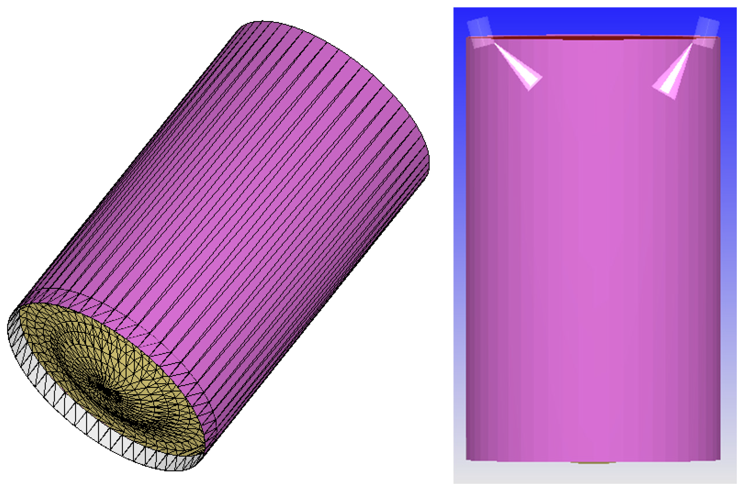
2.1. Engine Specifications and Computational Model Selection

In this study, CONVERGE v3.0 was used to model and set parameters for a two-stroke single cylinder engine. The engine parameters are shown in Table 1. The engine is equipped with two injectors that inject liquid ammonia and diesel at a given injection pressure. During engine operation, diesel is injected as a highly active fuel near the top dead center (TDC) of the piston, followed by liquid ammonia injection. The pilot diesel starts to burn soon after being injected into the cylinder, and then the liquid ammonia is added, and the combustion continues.
The engine cylinder was modeled, and Figure 1 shows the structure and mesh division of the model. Simulate a crank angle (CA) of 195 degree starting from −85 °CA after the top dead center (ATDC).
Table 2 lists the selected sub models. The physical models do a great effect on the simulation results. The RNG k-ε model is used to simulate turbulence inside the cylinder [27]. The KH-RT model adopts the traditional Lagrange method, which can accurately simulate the secondary fragmentation process of fuel droplets [28]. O’Rourke is used to describe the collision between droplets and cylinder wall [29]. The NTC model is used to represent the collision between droplets [30]. The Frosting model is used to represent the evaporation of droplets [31]. The SAGE model uses a transient chemical kinetics solver, ensuring the accuracy of the calculation [32]. The Extend Zeldovich model [33] is used to predict NOx emissions.
This study uses the mixing mechanism of ammonia diesel developed by Wang et al. [34], which has been proven to have satisfactory predictive accuracy. The N-heptane mechanism has been proven to be applicable for predicting diesel combustion, so N-heptane is used to replace of diesel in the reaction mechanism [14]. The mechanism includes a total of 495 reactions and 74 substances.

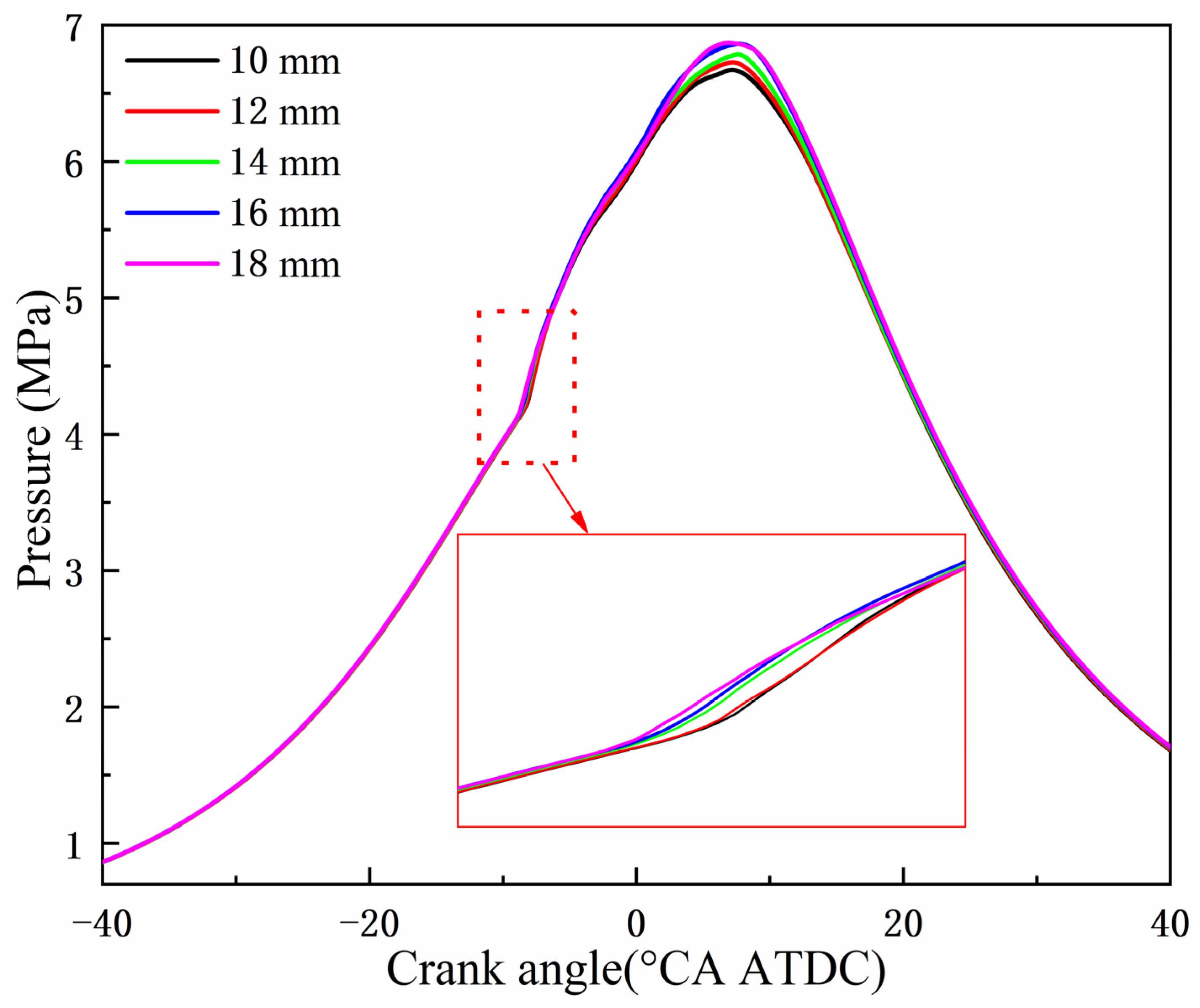
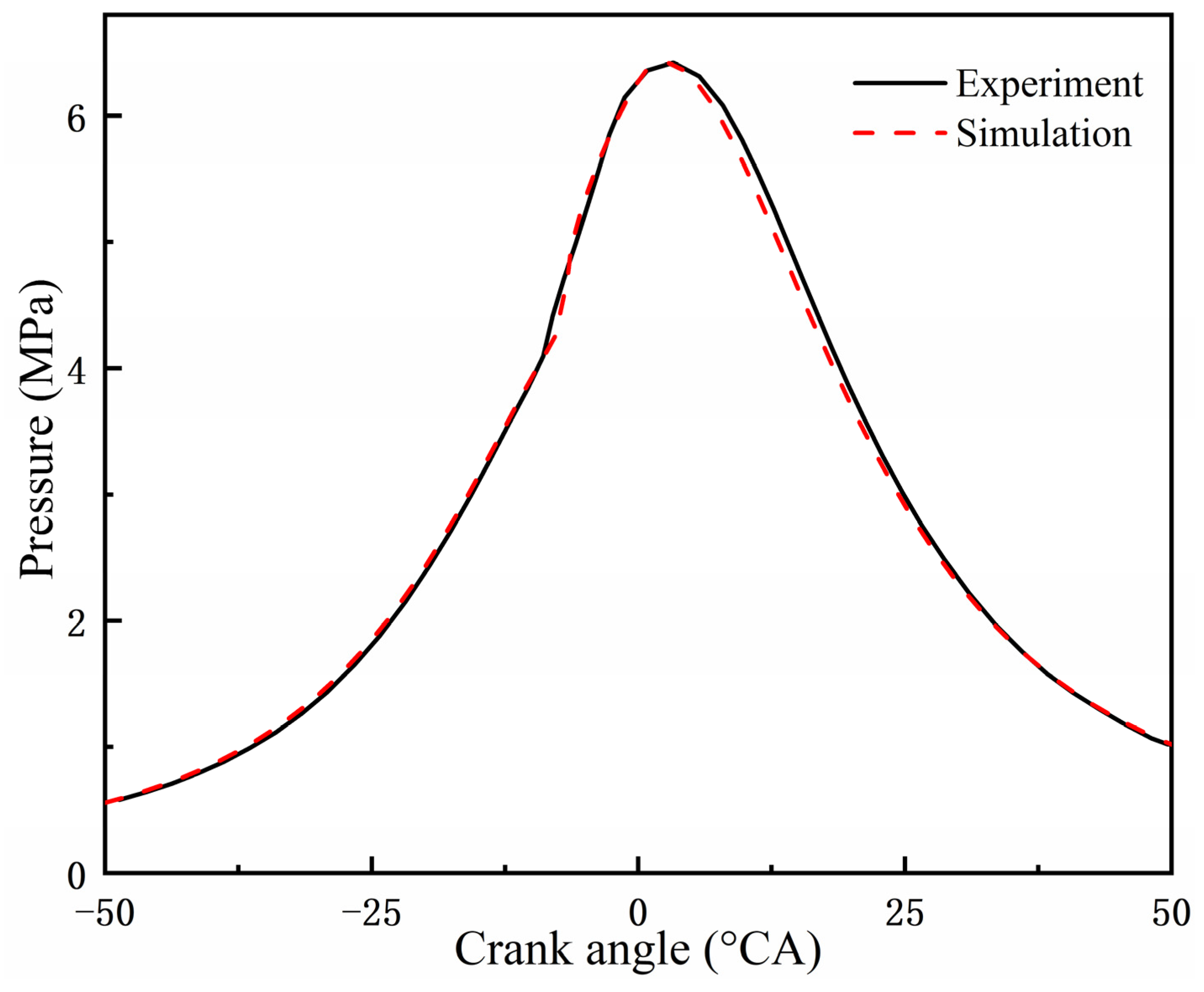
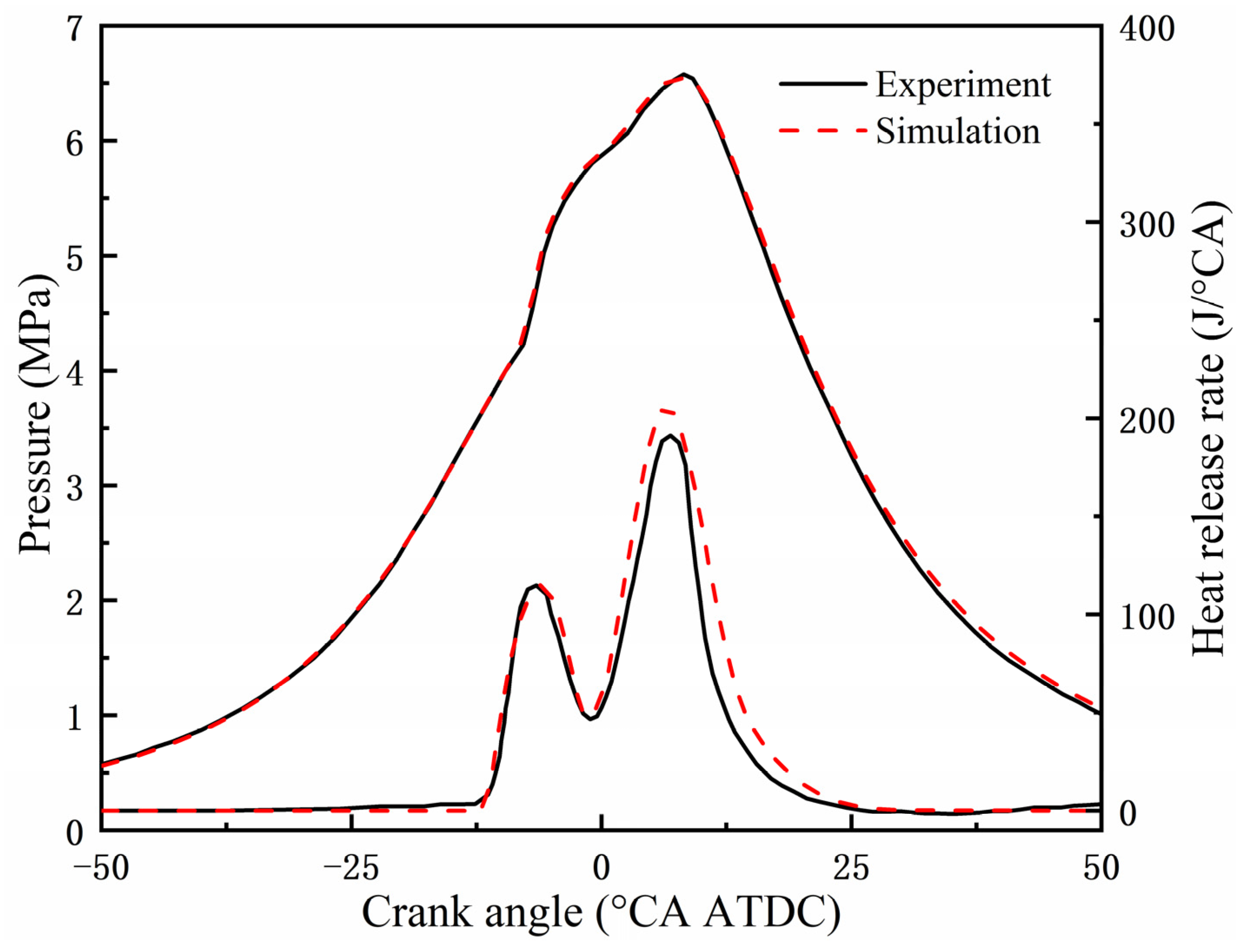
2.2. Grid Sensitivity and Model Validation

The size of the basic grid used in simulation has a great effect on the accuracy of the simulation [35,36]. Figure 2 shows the grid sensitivity analysis of the engine. In this study, five different basic grid sizes (10 mm, 12 mm, 14 mm, 16 mm, 18 mm) were selected to simulate combustion, with hexagonal prisms as the basic unit of simulation. From Figure 2, the trend of the cylinder pressure curve is consistent when different grid sizes are used, and as the basic grid size decreases, the peak cylinder pressure gradually decreases. The similarity of the cylinder pressure simulation results is high at grid sizes of 10 mm and 12 mm, with a maximum difference of 0.9%. Moreover, the pressure curves of the two basically overlap after the first inflection point. Therefore, the basic grid size of the calculation model is selected as 12 mm to ensure sufficient simulation accuracy and save computing resources. Among them, the number of grids for the engine combustion chamber model at the grid size of 12 mm is 85,669. The calculation is transient, with a maximum calculation step size of 1 × 10⁻⁴ s and a minimum calculation step size of 1 × 10⁻⁸ s.
Figure 3 and Figure 4 show the comparison of cylinder pressure experimental and simulation data under different AER conditions (0% and 50%, respectively), with the engine cylinder pressure experimental data sourced from Zhang et al. [13]’s study. The simulated start of diesel injection (SODI) timing is −14 °CA ATDC, and the simulated start of ammonia injection (SOAI) timing is −0.5 °CA ATDC. From Figure 3 and Figure 4, the simulated cylinder pressure at AER of 0% and 50% are consistent and basically consistent with the experimental data, with a maximum error of less than 5%. The experimental values of NOx emissions at AER of 0% and 50% are 215.02 ppm and 408.94 ppm, respectively. The simulated NOx emissions are 214.98 ppm and 408.71 ppm, respectively, and the errors are within an acceptable range. This indicates that the accuracy of the combustion chamber model simulation calculation for this engine is high and can ensure calculation accuracy.

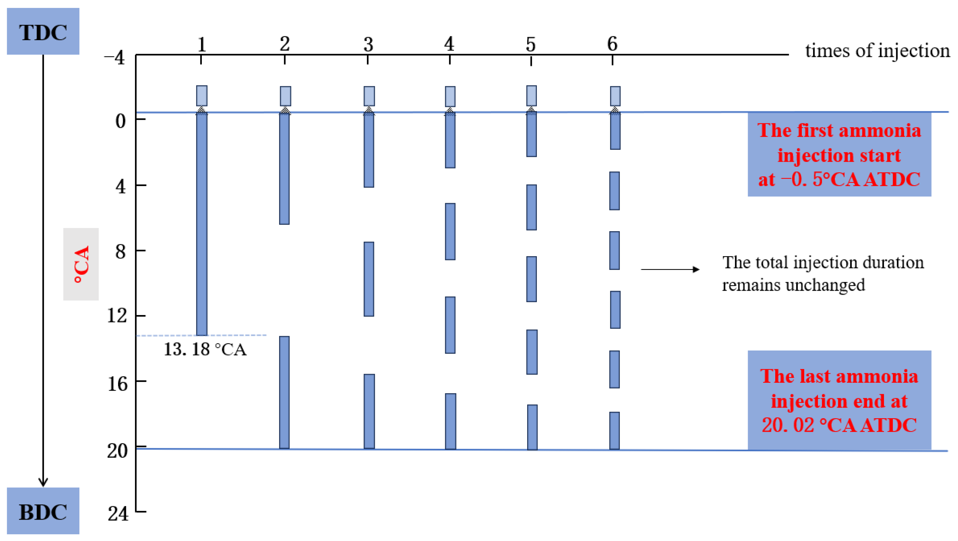
2.3. Multiple Injection Control Method

The numerical model includes two fuel injectors: one for injecting diesel and the other for liquid ammonia. Diesel, as a highly active fuel, is first injected into the cylinder, and then liquid ammonia is injected into the cylinder through different multiple injection schemes. Figure 5 shows a control method for multiple injection. At present, research on ADDF engines with direct injection of liquid ammonia mostly focuses on the case of a single ammonia injection. To achieve multiple injection while keeping the injection pressure constant, the duration of liquid ammonia injection will be extended. In order to eliminate interference as much as possible, only the effect of multiple injection of liquid ammonia on engine performance was studied. The solution adopted in this study is to control the total duration of multiple injection to remain unchanged, with crank angle equivalent to 1.5 times the duration of 1 times of injection, and to maintain the total period of liquid ammonia injection equal to the duration of 1 times of injection regardless of changes in the times of injection. It can be understood that, with a fixed ammonia injection pressure (AIP), introducing multiple injection actually increases the overall injection duration. When ammonia times of injection (TSOI) = 1, the injection duration is 13.68 °CA. Taking TSOI = 2 as an example, injection is divided into two stages. In the first stage, liquid ammonia injection starts from −0.5 °CA ATDC and lasts for 6.84 °CA. After an interval of 6.84 °CA, the second liquid ammonia injection starts from 13.18 °CA ATDC and lasts for 6.84 °CA until 20.02 °CA ATDC, and the entire injection process ends. By increasing TSOI to x, the duration of each segment of liquid ammonia injection is 13.68/x °CA, and the interval between each segment of liquid ammonia is 6.84/(x − 1) °CA. Precise control of each segment of liquid ammonia injection can be achieved by setting the injection pattern.

3. Results and Discussion

In this section, the influence of multiple injection on the combustion and emissions of liquid ammonia/diesel dual DI was discussed, mainly focusing on the times of injection for multiple injection, and optimizing the start of ammonia injection timing (SOAI) and ammonia injection pressure (AIP). Under all operating conditions in this study, the AER and diesel energy ratio were kept constant at 80% and 20%, respectively, and the diesel injection pressure (DIP) was kept constant at 100 MPa.

3.1. Effects of Times of Injection

3.1.1. Combustion Characteristics

Figure 6 and Figure 7 show the effect of ammonia times of injection (TSOI) on cylinder pressure and heat release rate (HRR) at 80% AER. With the increase of TSOI, the peak cylinder pressure gradually decreases and the peak phase advances. When TSOI > 2, there is a significant decrease in cylinder pressure in the later stage, indicating that the overall ammonia injection time is prolonged, which will affect the combustion after the top dead center and suppress the combustion in the later stage. However, this situation will be improved to some extent with the increase of TSOI. The instantaneous HRR can be seen from Figure 7. The overall heat release is divided into two parts. The first part is the pre injection diesel combustion heat release, which does not change with the different of TSOI. The second part is the combustion heat release dominated by liquid ammonia injection into the cylinder. With the increase of TSOI, the instantaneous HRR shows multiple peaks, but there are also unexpected situations. It can be seen that when TSOI = 2, liquid ammonia is supplied to the cylinder twice. Ideally, the heat release should be bimodal, but from Figure 7, the heat release is only unimodal actually. Similarly, when TSOI = 3, the heat release exhibits a bimodal pattern, and the second heat release peak is lower. Surprisingly, the peak heat release in the first stage is slightly higher than that when TSOI = 1, indicating that shorter liquid ammonia injection can promote higher quality combustion.
Figure 8 shows the phases of different combustion stages, including CA10, CA50, and combustion duration. CA10 represents the crank angle corresponding to when the heat release reaches 10% of the total heat release, while CA50 and CA90 are similar. Using multiple injection will result in earlier CA10 phase and shorter combustion duration, indicating that overall combustion becomes faster. As TSOI increases, both CA10 and CA50 show varying degrees of advancement, which may be due to a decrease in overall heat release. The combustion duration CA10–CA90 increases with the increase of TSOI, which is also easy to understand. Liquid ammonia is injected into the cylinder multiple times, and due to the existence of diffusion combustion, there will be some high-temperature areas in the cylinder, causing some ammonia to be oxidized and release heat, prolonging the overall combustion time. This situation will become more obvious with the increase of TSOI. However, the low laminar flame velocity and high latent heat of vaporization of ammonia, coupled with the downward stage of the piston, cannot meet the requirements of large-scale ignition.

3.1.2. Emission Characteristics

Figure 9 shows the CO2 and N2O emissions under different TSOI. CO2 and N2O are both GHG, and N2O has a greenhouse effect about 300 times that of CO2. The sensitivity of CO2 to TSOI is very low, although there are slight changes, the maximum change is less than 1%, and the effect of TSOI on it can be ignored. The emissions of N2O basically determine the emissions of GHG. When TSOI = 2, the total emissions of GHG are the lowest, with CO2 emissions of 216.22 ppm and N2O emissions of 1.38 ppm. As a whole, adding multiple injection will reduce N2O emissions, which is more pronounced when TSOI = 2, 3 and TSOI is large. Figure 10 shows the NOx and NH3 emissions under different TSOI. The overall NOx emissions show a trend of first decreasing and then increasing with the increase of TSOI, while the emissions of unburned ammonia show a significant increase. Similar results were obtained in Nyongesa’s study [37]. As mentioned earlier, multiple injection lead to combustion deterioration after the top dead center. In this case, after the liquid ammonia injected into the cylinder vaporizes, the portion involved in oxidation heat release becomes less, and the amount of unburned ammonia escaping increases. It is interesting that when TSOI = 3, NH3 and NOx emissions reach a relatively low state, with NH3 emissions of 52.77 ppm and NOx emissions of 107.61 ppm, which is likely due to more NH3 participating in chemical reactions related to NOx, ultimately leading to a decrease in both. In addition, the CO2 emissions in pure diesel mode are 451.25 ppm, and the NOx emissions are 214.98 ppm. After multiple injection of liquid ammonia, the emissions of both are reduced to varying degrees.

3.2. Optimization of Spray Strategy

3.2.1. Advance Ammonia Injection Timing

In the above study, the SOAI timing was kept constant at −0.5 °CA ATDC, and in order to control the AIP, the ammonia injection under multiple ammonia injection strategies stopped at 20.02 °CA ATDC. From the simulation results, it is not difficult to see that only the ammonia injected into the cylinder in the first two times can participate in a large amount of oxidation heat release, and the ammonia injected into the cylinder in the later stage cannot participate well in combustion, only undergoing chemical reactions under complex working conditions inside the cylinder. Advance the SOAI timing, on the one hand, allows the ammonia initially supplied to the cylinder to participate in combustion earlier, which is beneficial for increasing the cylinder temperature and providing a more favorable chemical thermal atmosphere for the subsequent liquid ammonia entering the cylinder. On the other hand, advancing the SOAI timing can control combustion to a greater extent near the top dead center, increase cylinder pressure through a smaller volume, and promote combustion.
Figure 11 shows the effect of different TSOI on cylinder pressure when SOAI timing is advanced to −8 °CA ATDC. As the SOAI timing advances, the peak cylinder pressure increases significantly and the peak phase advances, which is consistent with the expected results. This indicates that advancing the SOAI timing is beneficial for promoting combustion. Similar to Figure 6, as TSOI increases, the peak cylinder pressure decreases and the peak phase advances. However, the difference is that this change is not linear, but more like a repetition within a certain range. Figure 12 shows the effect of different TSOI on the HRR when SOAI timing is advanced to −8 °CA ATDC. Unlike Figure 7, when TSOI = 2, the HRR shows a double peak, indicating that advancing the SOAI timing can indeed improve the combustion of liquid ammonia injected into the cylinder for the second time. But when TSOI > 3, the HRR will not show multiple peaks corresponding to TSOI. For example, when TSOI = 3, liquid ammonia is supplied into the cylinder in three stages. Ideally, the HRR should exhibit three peaks, but Figure 12 also shows only two distinct peaks. This indicates that under the simulation conditions of this study, while keeping other parameters constant, it is difficult to achieve ideal multi-stage heat release by simply adjusting the SOAI timing.
Figure 13 shows the effect of different TSOI on CO2 and N2O emissions with advancing the SOAI timing to −8 °CA ATDC. Advancing the SOAI timing will lead to an overall increase in N2O emissions, with the largest increment exceeding 50% at TSOI = 2. This is because more ammonia participates in the oxidation reaction, resulting in an increase in N2O emissions. Similar to Figure 9, even if SOAI is advanced, TSOI still has little impact on CO2 emissions. Figure 14 shows the effects of different TSOI on NOx and NH3 emissions with advancing the SOAI timing to −8 °CA ATDC. Advancing the SOAI timing results in an overall increase in NOx emissions and a decrease in unburned NH3 emissions, which is consistent with the above results. As TSOI increases, NOx emissions show a trend of first decreasing and then increasing, while unburned NH3 emissions show the opposite trend of first decreasing and then increasing. When TSOI = 3, NOx emissions are the lowest, reducing by more than 50% compared to when TSOI = 1. In addition, although NOx emissions have increased, it still meets Tier III standards.

3.2.2. Effect of Ammonia Injection Pressure

In the above study, the diesel injection pressure and ammonia injection pressure were kept constant at 100 MPa and 65 MPa, respectively. In addition, the study by Xu et al. [38] optimized the ammonia energy fraction and injection strategy of a dual-fuel engine. The findings indicated that the increased injection pressure improved the combustion process and performance of the engine and reduced the unburned ammonia and N2O emissions. In Section 3.2.2, only the case of TSOI = 2 is discussed, and its effect on cylinder combustion and emissions is studied by changing the injection pressure of ammonia.
Figure 15 shows the effect of different AIP on cylinder pressure when TSOI = 2. With the increase of AIP, the peak cylinder pressure increases and the peak phase shifts forward, indicating that increasing the pressure of liquid ammonia DI has a significant promoting effect on combustion in the cylinder. On the premise of maintaining AER = 80% unchanged, increasing the injection pressure of liquid ammonia will shorten its injection duration, which is also the direct reason for the earlier peak cylinder pressure. In addition, increasing the injection pressure of liquid ammonia can improve its atomization effect, which to some extent compensates for the high latent heat of ammonia vaporization and helps promote combustion [39]. Figure 16 shows the effect of different AIP on the HRR when TSOI = 2. The heat release of diesel is basically the same, while the heat release dominated by ammonia oxidation is only unimodal, and with the increase of AIP, the peak heat release increases and the peak heat release phase advances. Increasing the injection pressure of liquid ammonia can greatly improve the combustion of liquid ammonia injected into the cylinder for the first time, but has little effect on the combustion of liquid ammonia injected into the cylinder for the second time.
Figure 17 shows the effect of different AIP on CO2 and N2O emissions at TSOI = 2. Since the main source of CO2 is diesel, changing the AIP has little effect on CO2 emissions. As the AIP increases, N2O emissions also increase, most likely due to higher AIP resulting in a larger contact surface between ammonia and the mixture, with more ammonia participating in the oxidation reaction. Figure 18 shows the effect of different AIP on NOx and NH3 emissions at TSOI = 2. The emissions of unburned NH3 decrease with the increase of AIP, while the overall NOx emissions show a trend of first increasing and then decreasing. However, from the perspective of quantitative relationship, changing the AIP has little effect on NOx and unburned NH3 emissions.

4. Conclusions

This paper simulated the effects of multiple injection strategy on engine combustion and emissions based on a validated ammonia diesel dual fuel model. On this basis, the study was conducted by advancing the start of ammonia injection (SOAI) timing to −8 °CA ATDC and increasing the ammonia injection pressure (AIP) with the times of injection (TSOI) = 2. The research conclusion is as follows:
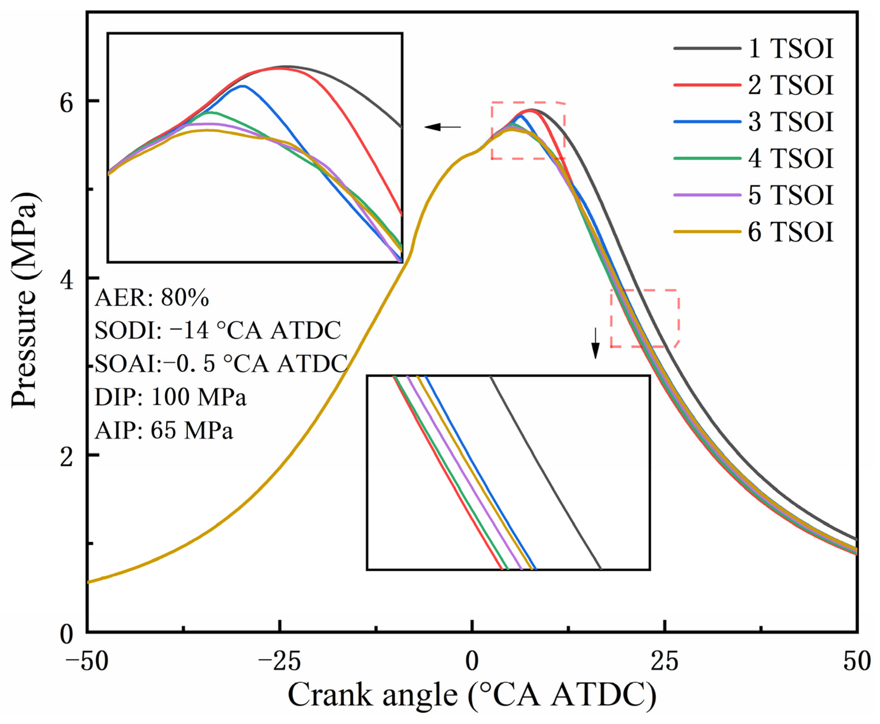
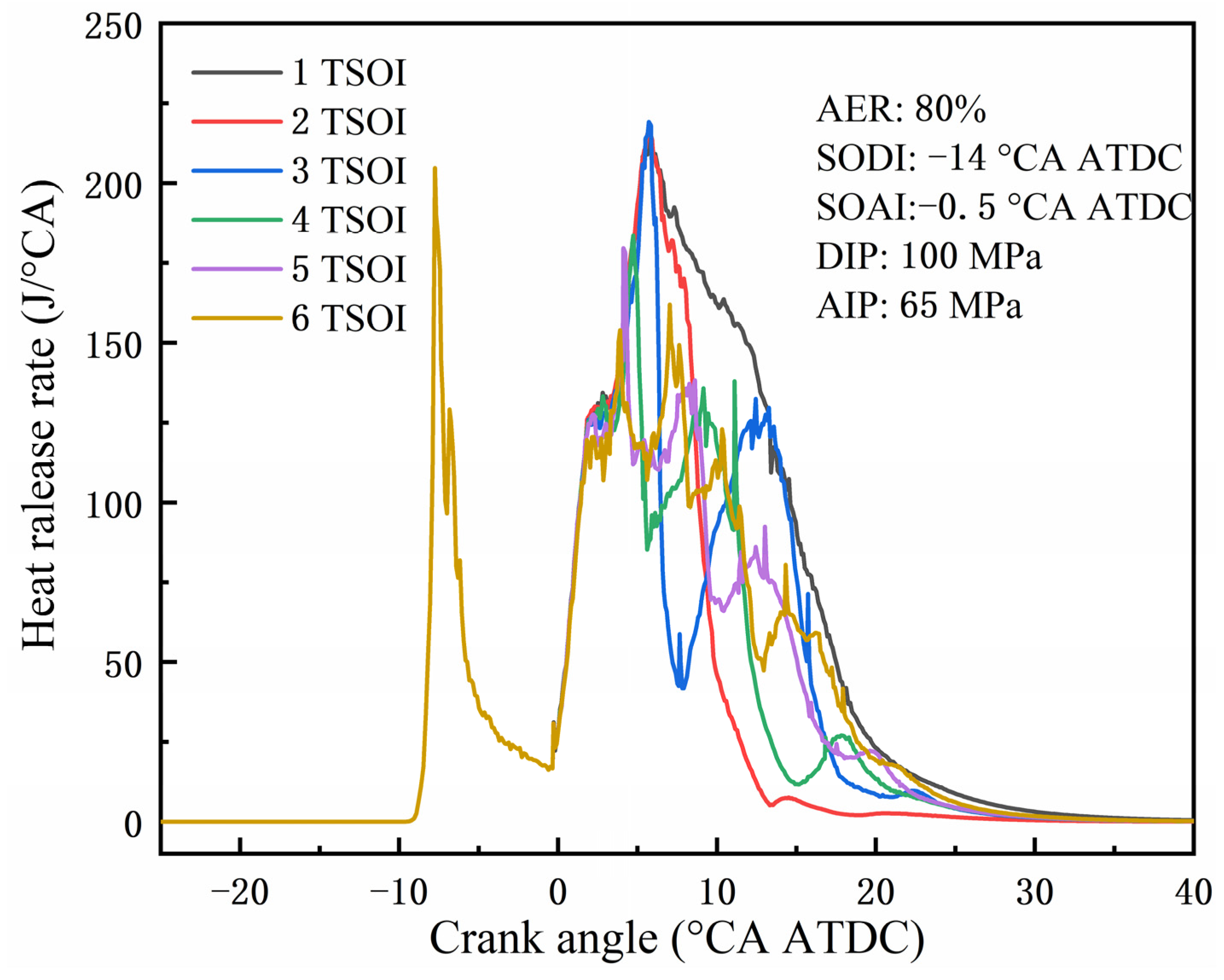
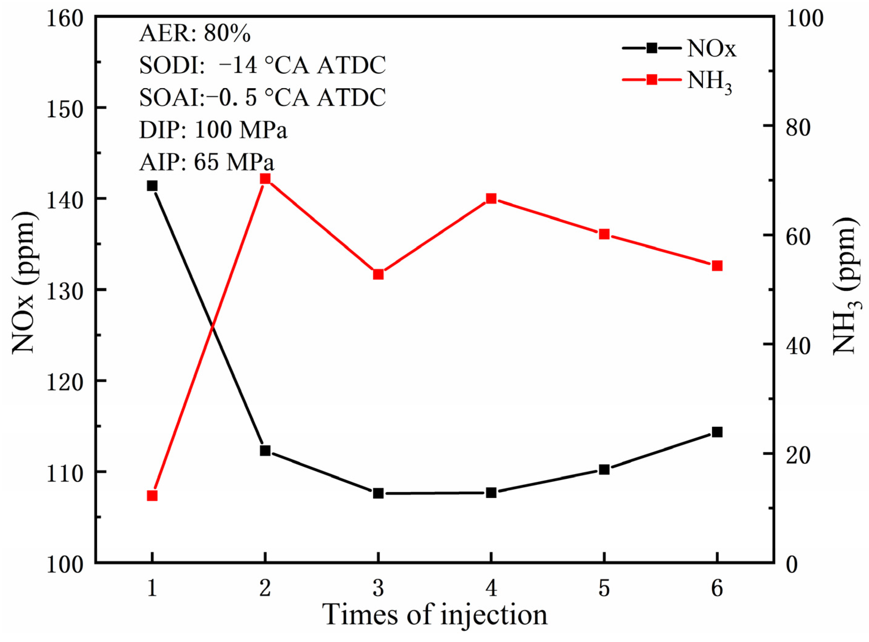
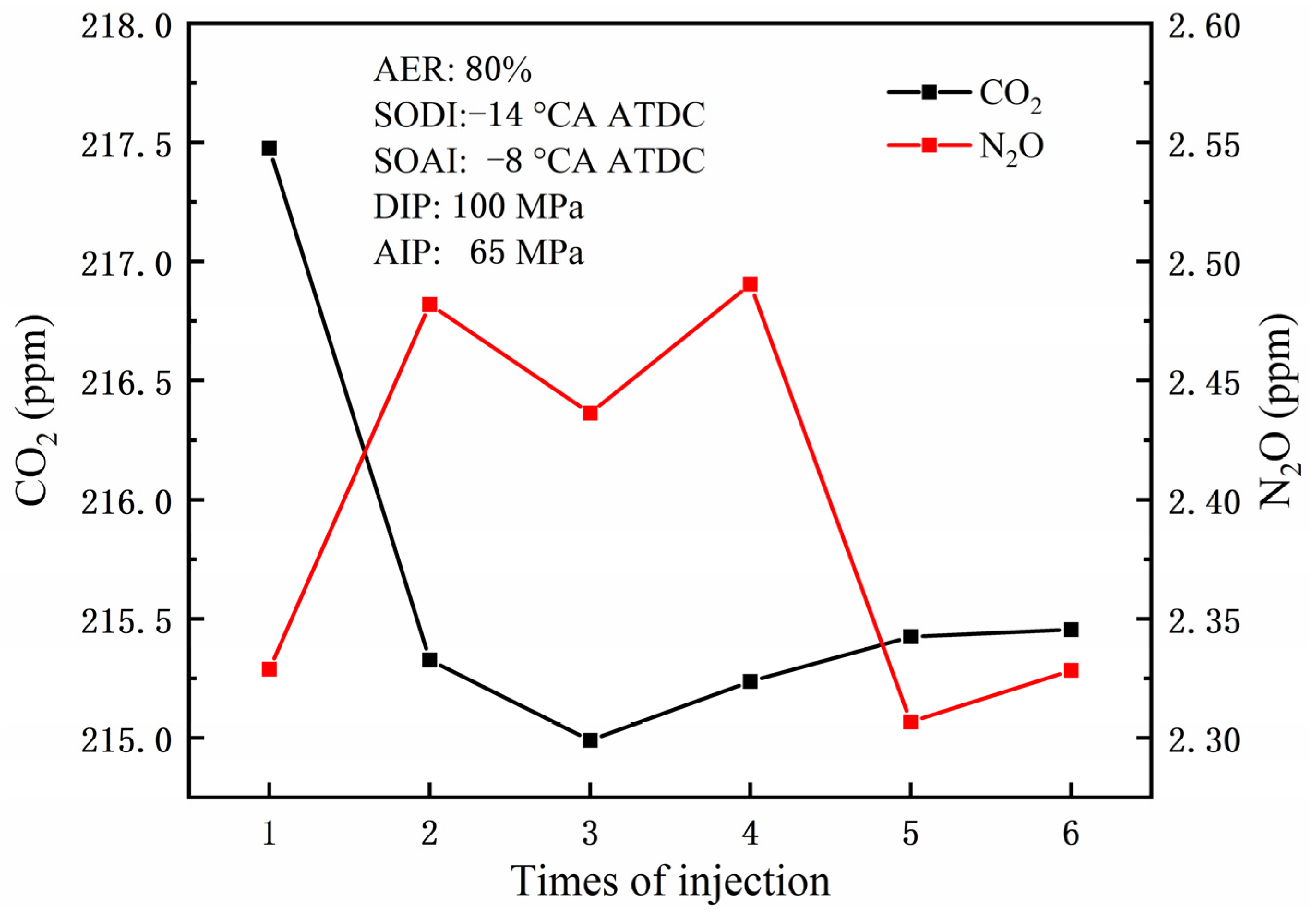
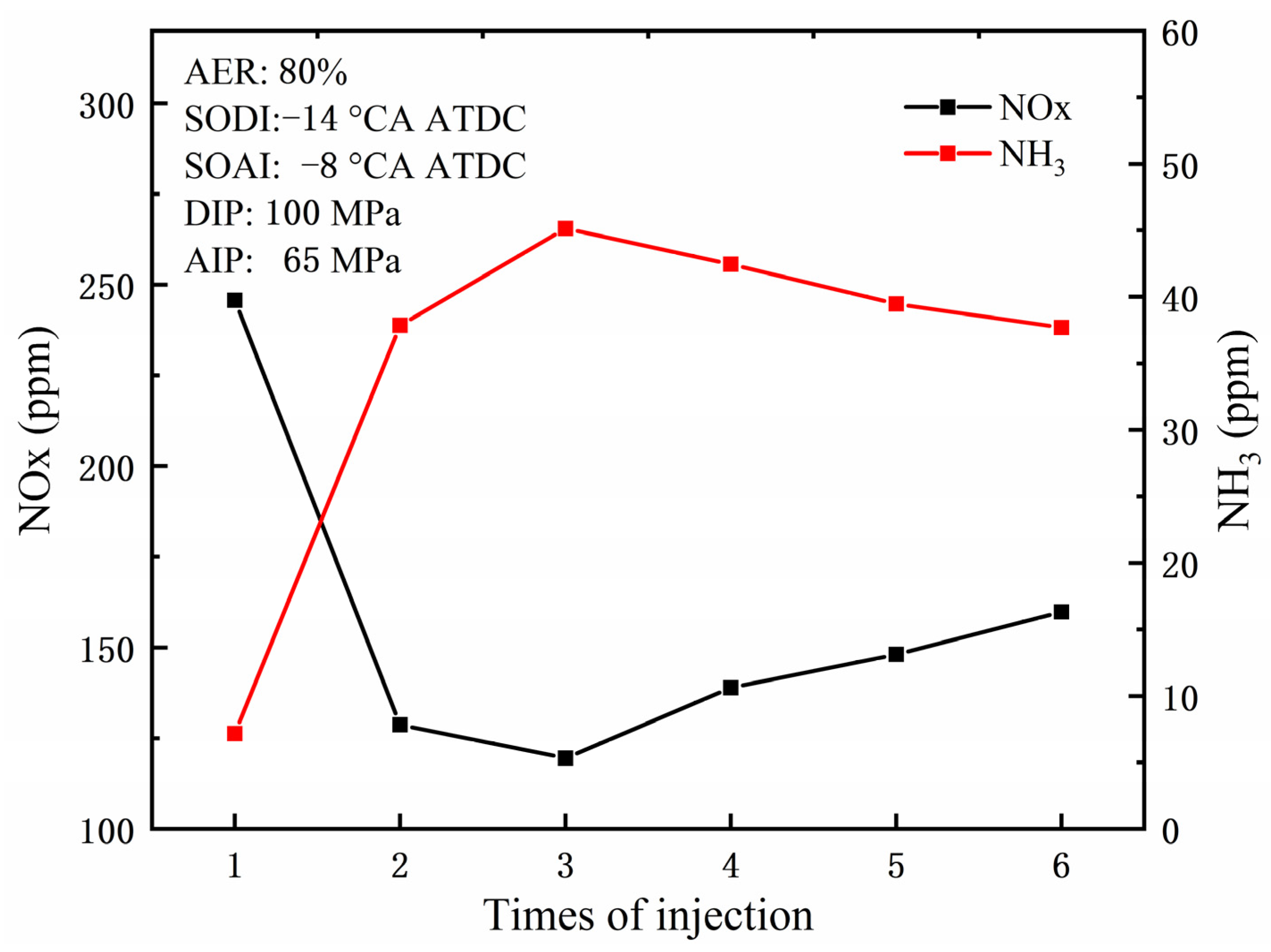
  • Using multiple injection can have a negative effect on the combustion of liquid ammonia injected later, but with an increase in the TSOI, this situation will be improved to some extent. With the increase of TSOI, the peak cylinder pressure stage is advanced, CA10 is advanced, the combustion duration is shortened, and the combustion speed is relatively faster than a single injection. Increasing TSOI will reduce GHG emissions and overall NOx emissions, but unburned NH3 emissions will increase. TSOI = 2, with the lowest N2O emissions at 1.38 ppm; TSOI = 3, with the lowest NOx emissions at 107.61 ppm.
  • Advancing the SOAI timing to −8 °CA ATDC leads to earlier injection of ammonia, allowing it to interact more effectively with the diesel-dominated combustion process, thereby improving overall combustion efficiency. The peak cylinder pressure has significantly increased, and the peak phase shifts forward as TSOI increases, but oscillates within a certain range. Advancing the SOAI timing has an improvement effect on later combustion. When TSOI = 2, the heat release shows a clear bimodal pattern, while the heat release rate at SOAI = −0.5 °CA ATDC only shows a unimodal pattern. The overall N2O and NOx emissions have increased, while unburned NH3 emissions have decreased. But when SOAI advanced to −8 °CA ATDC, NOx showed a decreasing trend with the increase of TSOI, and the reduction was not small. When TSOI = 3, NOx emissions reached their lowest point, which was more than 50% lower than a single ammonia injection.
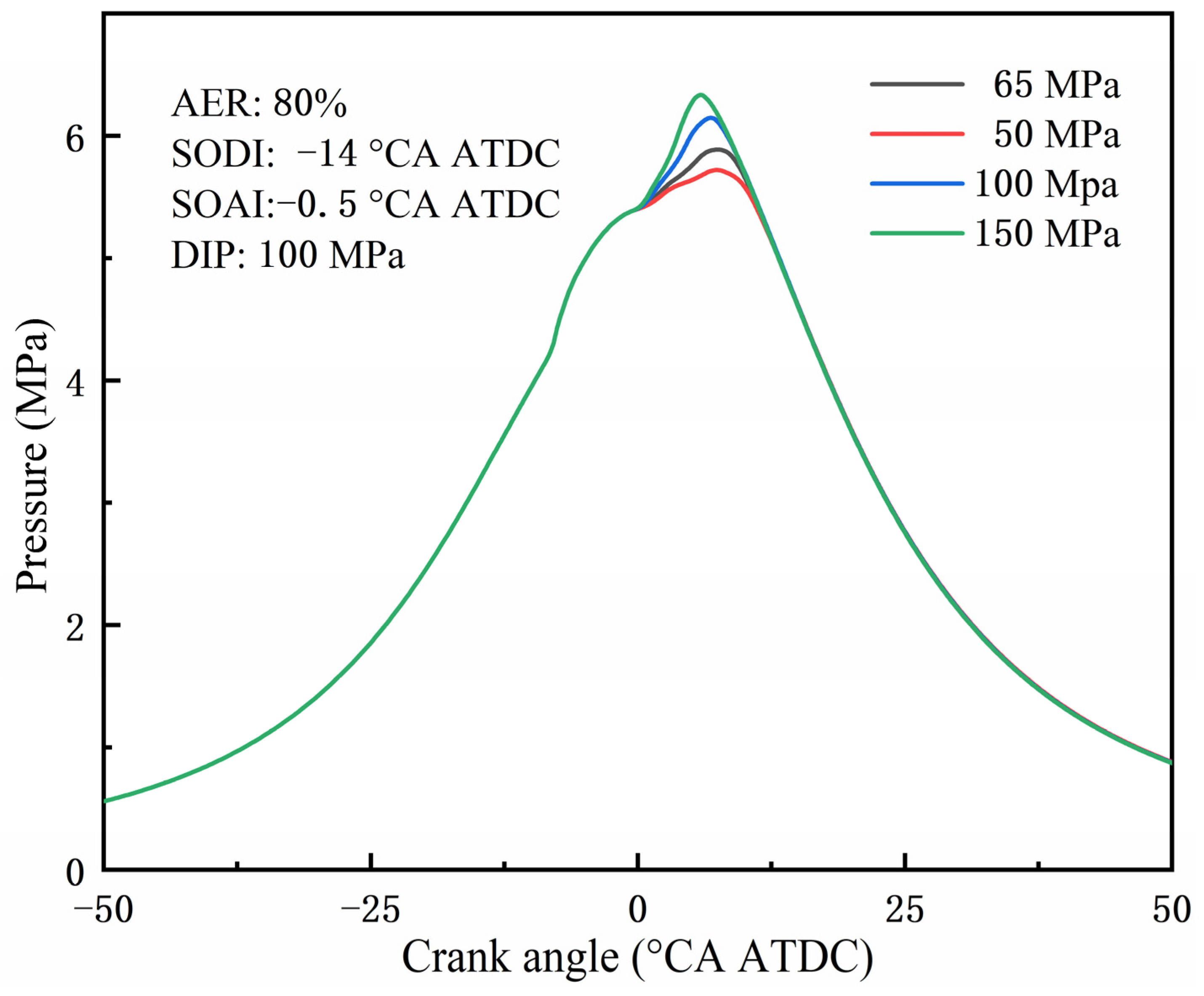
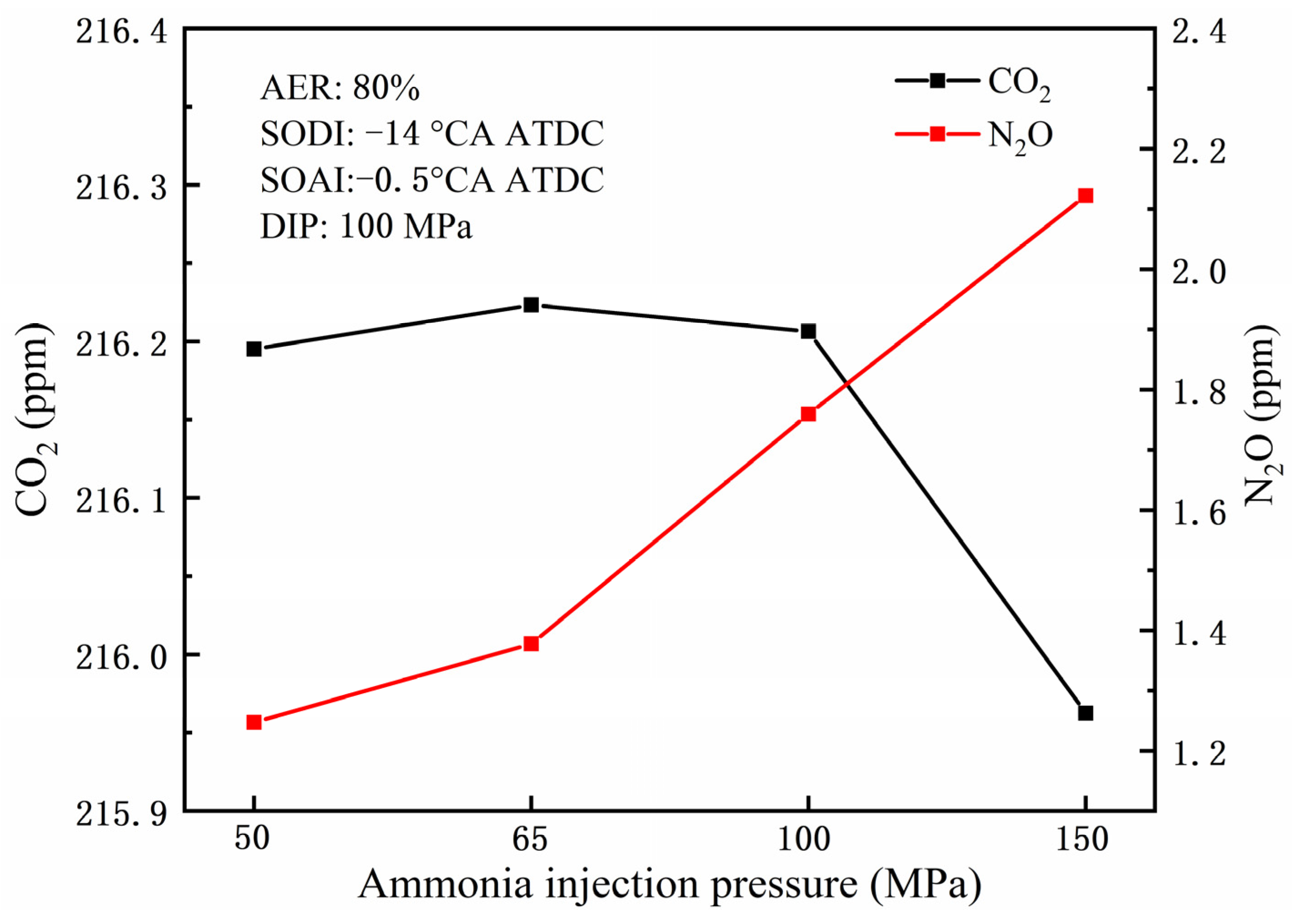
  • Increasing the injection pressure of ammonia can enhance its contact with the mixed gas and promote combustion. When TSOI = 2, increasing AIP from 50 MPa to 150 MPa increases the peak cylinder pressure, and there is a significant increase in the peak heat release dominated by ammonia, but only a single peak, indicating that increasing AIP alone cannot achieve multi-stage heat release. N2O emissions increase with the increase of AIP, which is due to more ammonia participating in the oxidation reaction, while CO2, NOx, and NH3 emissions, although changing, are small.

Author Contributions

Conceptualization, Y.W. and O.I.A.; methodology, Z.C.; software, Y.W.; validation, Y.W. and Z.P.; formal analysis, Z.C.; investigation, Z.P. and Y.W.; resources, Y.W.; data curation, Z.P.; writing—original draft preparation, Y.W.; writing—review and editing, O.I.A.; visualization, Y.W.; supervision, O.I.A.; project administration, O.I.A.; funding acquisition, Z.C. All authors have read and agreed to the published version of the manuscript.

Funding

This work in this paper was supported by the National Natural Science Foundation of China (Grant No. 52461046).

Institutional Review Board Statement

Not applicable.

Informed Consent Statement

Not applicable.

Data Availability Statement

Data are available from the corresponding author and can be shared upon reasonable request.

Conflicts of Interest

The authors confirm that there are no known conflicts of interest associated with this publication. The authors confirm that the results and interpretations reported in the manuscript are original and have not been plagiarized.

Nomenclature

ADDFAmmonia diesel dual fuel
AERAmmonia energy ratio
AIPAmmonia injection pressure
ATDCAfter the top dead center
CACrank angle
CA10Crank angle corresponding to 10% of the total heat release rate
CA50Crank angle corresponding to 50% of the total heat release rate
CA90Crank angle corresponding to 90% of the total heat release rate
CICompression ignition
COCarbon monoxide
DIDirect injection
GHGGreenhouse gas
HRRHeat release rate
ITEIndicated thermal efficiency
NOxNitrogen oxides
N2ONitrous oxide
SOAIState of ammonia injection
SODIStart of diesel injection
TDCTop dead center
TSOIThe times of injection

References

  1. Chen, Y.; Zhang, J.; Zhang, Z.; Zhang, B.; Hu, J.; Zhong, W.; Ye, Y.J. A comprehensive review of stability enhancement strategies for metal nanoparticle additions to diesel/biodiesel and their methods of reducing pollutant. Process Saf. Environ. Prot. 2024, 183, 1258–1282. [Google Scholar] [CrossRef]
  2. Deng, S.; Mi, Z. A review on carbon emissions of global shipping. Mar. Dev. 2023, 1, 4. [Google Scholar] [CrossRef]
  3. Wu, Z.; Huang, X.; Chen, R.; Mao, X.; Qi, X.J. The United States and China on the paths and policies to carbon neutrality. J. Environ. Manag. 2022, 320, 115785. [Google Scholar] [CrossRef] [PubMed]
  4. Chen, G.; Wei, F.; Zhang, K.; Xiao, R.; Wang, Z.; Yang, S.J. Investigation on combustion characteristics and gas emissions of a high-pressure direct-injection natural gas engine at different combustion modes. Energy Convers. Manag. 2023, 277, 116617. [Google Scholar] [CrossRef]
  5. Dong, D.; Wei, F.; Long, W.; Dong, P.; Tian, H.; Tian, J.; Wang, P.; Lu, M.; Meng, X.J. Optical investigation of ammonia rich combustion based on methanol jet ignition by means of an ignition chamber. Fuel 2023, 345, 128202. [Google Scholar] [CrossRef]
  6. Frost, J.; Tall, A.; Sheriff, A.M.; Schönborn, A.; Hellier, P. An experimental and modelling study of dual fuel aqueous ammonia and diesel combustion in a single cylinder compression ignition engine. Int. J. Hydrogen Energy 2021, 46, 35495–35510. [Google Scholar] [CrossRef]
  7. Dimitriou, P.; Javaid, R. A review of ammonia as a compression ignition engine fuel. Int. J. Hydrogen Energy 2020, 45, 7098–7118. [Google Scholar] [CrossRef]
  8. Kurien, C.; Mittal, M. Review on the production and utilization of green ammonia as an alternate fuel in dual-fuel compression ignition engines. Energy Convers. Manag. 2022, 251, 114990. [Google Scholar] [CrossRef]
  9. Gill, S.; Chatha, G.; Tsolakis, A.; Golunski, S.E.; York, A.J.E. Assessing the effects of partially decarbonising a diesel engine by co-fuelling with dissociated ammonia. Int. J. Hydrogen Energy 2012, 37, 6074–6083. [Google Scholar] [CrossRef]
  10. da Rocha, R.C.; Costa, M.; Bai, X.-S. Chemical kinetic modelling of ammonia/hydrogen/air ignition, premixed flame propagation and NO emission. Fuel 2019, 246, 24–33. [Google Scholar] [CrossRef]
  11. Shin, J.; Park, S. Numerical analysis and optimization of combustion and emissions in an ammonia-diesel dual-fuel engine using an ammonia direct injection strategy. Energy 2024, 289, 130014. [Google Scholar] [CrossRef]
  12. Niki, Y.; Nitta, Y.; Sekiguchi, H.; Hirata, K. Diesel fuel multiple injection effects on emission characteristics of diesel engine mixed ammonia gas into intake air. J. Eng. Gas Turbines Power 2019, 141, 061020. [Google Scholar] [CrossRef]
  13. Zhang, Z.; Long, W.; Dong, P.; Tian, H.; Tian, J.; Li, B.; Wang, Y. Performance characteristics of a two-stroke low speed engine applying ammonia/diesel dual direct injection strategy. Fuel 2023, 332, 126086. [Google Scholar] [CrossRef]
  14. Li, T.; Zhou, X.; Wang, N.; Wang, X.; Chen, R.; Li, S.; Yi, P. A comparison between low-and high-pressure injection dual-fuel modes of diesel-pilot-ignition ammonia combustion engines. J. Energy Inst. 2022, 102, 362–373. [Google Scholar] [CrossRef]
  15. Zhou, X.; Li, T.; Wang, N.; Wang, X.; Chen, R.; Li, S. Pilot diesel-ignited ammonia dual fuel low-speed marine engines: A comparative analysis of ammonia premixed and high-pressure spray combustion modes with CFD simulation. Renew. Sustain. Energy Rev. 2023, 173, 113108. [Google Scholar] [CrossRef]
  16. Liu, L.; Wu, Y.; Wang, Y. Numerical investigation on the combustion and emission characteristics of ammonia in a low-speed two-stroke marine engine. Fuel 2022, 314, 122727. [Google Scholar] [CrossRef]
  17. Liu, J.; Liu, J. Experimental investigation of the effect of ammonia substitution ratio on an ammonia-diesel dual-fuel engine performance. J. Clean. Prod. 2024, 434, 140274. [Google Scholar] [CrossRef]
  18. Zhu, J.; Zhou, D.; Yang, W.; Qian, Y.; Mao, Y.; Lu, X. Investigation on the potential of using carbon-free ammonia in large two-stroke marine engines by dual-fuel combustion strategy. Energy 2023, 263, 125748. [Google Scholar] [CrossRef]
  19. Pei, Y.; Wang, D.; Jin, S.; Gu, Y.; Wu, C.; Wu, B. A quantitative study on the combustion and emission characteristics of an Ammonia-Diesel Dual-fuel (ADDF) engine. Fuel Process. Technol. 2023, 250, 107906. [Google Scholar] [CrossRef]
  20. Yousefi, A.; Guo, H.; Dev, S.; Liko, B.; Lafrance, S. Effects of ammonia energy fraction and diesel injection timing on combustion and emissions of an ammonia/diesel dual-fuel engine. Fuel 2022, 314, 122723. [Google Scholar] [CrossRef]
  21. Nadimi, E.; Przybyła, G.; Løvås, T.; Peczkis, G.; Adamczyk, W. Experimental and numerical study on direct injection of liquid ammonia and its injection timing in an ammonia-biodiesel dual injection engine. Energy 2023, 284, 129301. [Google Scholar] [CrossRef]
  22. Mi, S.; Zhang, J.; Shi, Z.; Wu, H.; Zhao, W.; Qian, Y.; Lu, X. Optimization of direct-injection ammonia-diesel dual-fuel combustion under low load and higher ammonia energy ratios. Fuel 2024, 375, 132611. [Google Scholar] [CrossRef]
  23. Sun, W.; Zeng, W.; Guo, L.; Zhang, H.; Yan, Y.; Lin, S.; Zhu, G.; Jiang, M.; Yu, C.; Wu, F. An optical study of the combustion and flame development of ammonia-diesel dual-fuel engine based on flame chemiluminescence. Fuel 2023, 349, 128507. [Google Scholar] [CrossRef]
  24. Førby, N.; Thomsen, T.B.; Cordtz, R.F.; Bræstrup, F.; Schramm, J. Ignition and combustion study of premixed ammonia using GDI pilot injection in CI engine. Fuel 2023, 331, 125768. [Google Scholar] [CrossRef]
  25. Yousefi, A.; Guo, H.; Dev, S.; Lafrance, S.; Liko, B. A study on split diesel injection on thermal efficiency and emissions of an ammonia/diesel dual-fuel engine. Fuel 2022, 316, 123412. [Google Scholar] [CrossRef]
  26. Liu, X.; Wang, Q.; Zhong, W.; Jiang, P.; Xu, M.; Guo, B. Optical diagnostics in impact of ammonia energy ratio and diesel split ratio on combustion process and flame propagation in an Ammonia-Diesel Dual-Fuel engine. Fuel 2024, 364, 131074. [Google Scholar] [CrossRef]
  27. Han, Z.; Reitz, R. Turbulence modeling of internal combustion engines using RNG κ-ε models. Combust. Sci. Technol. 1995, 106, 267–295. [Google Scholar] [CrossRef]
  28. Reitz, R.D.; Bracco, F.V. Mechanism of breakup of round liquid jets. Encycl. Fluid Mech. 1986, 3, 223–249. [Google Scholar]
  29. Anthony Amsden, L. A Block-Structured KIVA Program for Engines with Vertical or Canted Valves; Los Alamos National Laboratory (LANL): Los Alamos, NM, USA, 1999. [Google Scholar]
  30. Schmidt, D.P.; Rutland, C. A new droplet collision algorithm. J. Comput. Phys. 2000, 164, 62–80. [Google Scholar] [CrossRef]
  31. Amsden, A.A.; O’Rourke, P.J.; Butler, T.D. KIVA-II: A computer program for chemically reactive flows with sprays. Tech. Rep. 1989, 89, 27975. [Google Scholar]
  32. Senecal, P.; Pomraning, E.; Richards, K.; Briggs, T.; Choi, C.; McDavid, R.; Patterson, M.A. Multi-dimensional modeling of direct-injection diesel spray liquid length and flame lift-off length using CFD and parallel detailed chemistry. SAE Tech. Pap. 2003, 112, 1331–1351. [Google Scholar]
  33. Anetor, L.; Odetunde, C.; Osakue, E.E. Computational analysis of the extended Zeldovich mechanism. Arab. J. Sci. Eng. 2014, 39, 8287–8305. [Google Scholar] [CrossRef]
  34. Wang, B.; Dong, S.; Jiang, Z.; Gao, W.; Wang, Z.; Li, J.; Yang, C.; Wang, Z.; Cheng, X. Development of a reduced chemical mechanism for ammonia/ n-heptane blends. Fuel 2023, 338, 127358. [Google Scholar] [CrossRef]
  35. Khana, S.; Panuab, R.; Bose, P.K. Combined effects of piston bowl geometry and spray pattern on mixing, combustion and emissions of a diesel engine: A numerical approach. Fuel 2018, 225, 203–217. [Google Scholar] [CrossRef]
  36. Liu, L.; Wu, Y.; Wang, Y. Numerical investigation on knock characteristics and mechanism of large-bore natural gas dual-fuel marine engine. Fuel 2022, 310, 122298. [Google Scholar] [CrossRef]
  37. Nyongesa, A.J.; Kim, J.K.; Lee, W.-J. Investigation on the combustion of ammonia using direct high/medium-pressure-Otto injection approach in a diesel two-stroke marine slow speed engine. J. Energy Inst. 2024, 114, 101641. [Google Scholar] [CrossRef]
  38. Xu, X.; Wang, Z.; Qu, W.; Song, M.; Fang, Y.; Feng, L. Optimizations of energy fraction and injection strategy in the ammonia-diesel dual-fuel engine. J. Energy Inst. 2024, 112, 101455. [Google Scholar] [CrossRef]
  39. Tian, J.; Zhang, X.; Cui, Z.; Ye, M.; Wang, Y.; Xu, T.; Dong, P. Visualization study on ammonia/diesel dual direct injection combustion characteristics and interaction between sprays. Energy Convers. Manag. 2024, 299, 117857. [Google Scholar] [CrossRef]
Figure 1. Simulation model.
Atmosphere 16 00094 g001
Figure 2. Effect of base grid size on cylinder pressure.
Atmosphere 16 00094 g002
Figure 3. Simulation verification results of pure diesel mode.
Atmosphere 16 00094 g003
Figure 4. Simulation verification results of AER of 50%.
Atmosphere 16 00094 g004
Figure 5. Multiple injection method.
Atmosphere 16 00094 g005
Figure 6. Effect of TSOI on cylinder pressure.
Atmosphere 16 00094 g006
Figure 7. Effect of TSOI on heat release rate.
Atmosphere 16 00094 g007
Figure 8. CA10, CA50 and CA90 under different TSOI.
Atmosphere 16 00094 g008
Figure 9. CO2 and N2O emissions.
Atmosphere 16 00094 g009
Figure 10. NOx and NH3 emissions.
Atmosphere 16 00094 g010
Figure 11. Effect of TSOI on cylinder pressure with SOAI timing of −8 °CA ATDC.
Atmosphere 16 00094 g011
Figure 12. Effect of TSOI on heat release rate with SOAI timing of −8 °CA ATDC.
Atmosphere 16 00094 g012
Figure 13. CO2 and N2O emissions with SOAI timing of −8 °CA ATDC.
Atmosphere 16 00094 g013
Figure 14. NOx and NH3 emissions with SOAI timing of −8 °CA ATDC.
Atmosphere 16 00094 g014
Figure 15. The effect of different ammonia injection pressure on cylinder pressure with TSOI = 2.
Atmosphere 16 00094 g015
Figure 16. The effect of different ammonia injection pressure on heat release rate with TSOI = 2.
Atmosphere 16 00094 g016
Figure 17. CO2 and N2O emissions under different ammonia injection pressure (AIP) with TSOI = 2.
Atmosphere 16 00094 g017
Figure 18. NOx and NH3 emissions under different ammonia injection pressure (AIP) with TSOI = 2.
Atmosphere 16 00094 g018
Table 1. Engine parameters.
ParametersValue
Bore and stroke (mm)150 × 225
Engine speed (rpm)375
Effective compression ratio13.8
Ammonia/diesel injection modeDirect injection in cylinder
Ammonia injection pressure (MPa)65
Diesel injection pressure (MPa)100
Table 2. Selection of sub models.
ProjectsModels
TurbulenceRNG k-ε [27]
Droplet breakupKH-RT [28]
Droplet wall collisionO’Rourke [29]
Droplet CollisionNTC [30]
Droplet evaporationFrossling [31]
CombustionSAGE [32]
NOx emissionsExtend Zeldovich [33]
Disclaimer/Publisher’s Note: The statements, opinions and data contained in all publications are solely those of the individual author(s) and contributor(s) and not of MDPI and/or the editor(s). MDPI and/or the editor(s) disclaim responsibility for any injury to people or property resulting from any ideas, methods, instructions or products referred to in the content.

