Abstract
Based on the Quick Access Recorder (QAR) data covering over 9000 routes in China, the monthly and intra-day distribution characteristics of aircraft bumpiness at different levels were analyzed, and the relationships between the eddy dissipation rate (EDR) and other aircraft flight status elements during bumpiness occurrence were also analyzed. Afterward, aircraft bumpiness routes were constructed using 19 machine learning models. The analyses show that (1) aircraft bumpiness was mainly concentrated between 0:00 a.m. and 17:00 p.m. Severe aircraft bumpiness occurred more frequently in the early morning in January, especially between 5:00 a.m. and 6:00 a.m., and moderate bumpiness always occurred from 3:00 a.m. to 11:00 a.m. (2) The relationship between the left and right attack angles and aircraft bumpiness on the routes was more symmetrical, with a center at 0 degrees, unlike in the approach area where the hotspots were mainly concentrated in the range of −5 to 0 degrees. In the approach area, the larger the Mach number, the more severe the bumpiness. (3) The performances of the Automatic Relevance Determination Regression (ARD), Partial Least Squares Regression (PLS), Elastic-Net Regression (ENR), Classification and Regression Tree (CART), Passive Aggressive Regression (PAR), Random Forest (RF), Stochastic Gradient Descent Regression (SGD), and Tweedie Regression (TWD) based models were relatively good, while the performances of the Huber Regression (HUB), Least Angle Regression (LAR), Polynomial Regression (PLN), and Ridge Regressor (RR) based models were very poor. The aircraft bumpiness prediction models performed best over the approach area of ZBDT (airport in Datong), ZULS (airport in Lhasa), ZPPP (airport in Kunming), and ZLQY (airport in Qingyang). The model performed best in predicting the ZLLL-ZBDT air route (flight routes for Lanzhou to Datong) with different prediction times.
1. Introduction
Air transportation has gradually occupied an important position in the modern transportation industry; however, its safety has increasingly raised societal concerns. Air turbulence, which causes anxiety among airline passengers and induces aircraft bumpiness, is a typical risk that poses a serious threat to civil aviation safety. Eddy currents are a useful concept for studying the mechanism of air turbulence [1,2,3]. The eddy dissipation rate (EDR) based on eddy currents may be an ideal measurement method for evaluating aircraft bumpiness caused by air turbulence [4] by determining the energy loss of viscous forces in turbulence. The EDR is the rate at which turbulent energy is absorbed by decomposing eddies into smaller and smaller eddies until it is ultimately converted into heat by viscous forces. The larger the EDR, the stronger the turbulence. Therefore, the EDR is usually used to describe the amplitude of turbulence around an aircraft, thereby characterizing the bumpiness encountered by the aircraft [5].
Many scholars have used EDR forecasting to predict aircraft bumpiness. EDRs are commonly obtained using Doppler weather radar, Doppler light detection and ranging (LIDAR), or a combination of both methods [6,7,8,9,10]. These EDRs can provide assistance in predicting low-level aircraft bumpiness. Most input data for aircraft bumpiness warnings come from EDRs in the Quick Access Recorder (QAR) data. Kim et al. [11] used logarithmic normal mapping technology to estimate the EDR, thereby reducing aircraft bumpiness caused by convective turbulence in South Korea in 2018. An EDR prediction model based on data from over 6000 conventional flights and classification and regression-supervised machine learning models to predict aircraft turbulence was built by Emara et al. [12]. This model performed well in predicting EDRs and analyzing turbulence severity approximately 10 s before encountering turbulence events. Cai et al. [13] calculated multiple turbulence indices reflecting clear air and mountain wave turbulence using China Meteorological Administration Mesoscale Weather Numerical Forecasting System (CMA-MESO) results. They then converted the indices into EDRs to predict aircraft bumpiness. This roughly reflected the different types of turbulence scenarios in most regions of China during 2018–2020. Based on the assumption that EDRs follow a log-normal distribution, Sharman and Pearson [14] developed an EDR prediction strategy for climatological peak EDR data from an in situ-equipped aircraft in conjunction with the distribution of computed diagnostic values. Pearson and Sharman [15] proposed a new EDR prediction method that combines recent short-term turbulence forecasts with all currently available direct turbulence observations and inferences from other sources based on Graphical Turbulence Guidance.
Currently, it is common to predict turbulence or aircraft bumpiness based on the relationship between numerical weather prediction model results and the EDR, such as using the CMA-MESO [13], Weather Research and Forecasting (WRF) [16], Graphical Turbulence Guidance (GTG) [15,17], global Korean deterministic aviation turbulence guidance (G-KTG), or a global Korean probabilistic turbulence forecast (G-KPT) system [18]. Predicting turbulence through the numerical weather prediction model has certain advantages, such as the ability to cover sparsely observed high altitudes and having a longer prediction time for future turbulence.
The bottleneck of aircraft turbulence prediction mainly includes the following aspects: (1) More precise monitoring of the aircraft flight status is required. Aircraft bumpiness prediction requires accurate monitoring of aircraft acceleration, attitude, airflow, and other data. (2) More precise models are needed. Aircraft bumpiness prediction is usually based on mathematical models and algorithms, which need to describe the interaction between aircraft and meteorological conditions as accurately as possible. However, the accuracy of the model may be limited by various factors. (3) Accurate meteorological data are required. Aircraft bumpiness prediction relies on accurate meteorological data; however, obtaining accurate meteorological data may be difficult, especially in high-altitude areas. (4) Reducing human errors is necessary [19].
For time resolution, predictions based on QAR data seem to have more advantages as QAR data provide more accurate monitoring of the aircraft flight status. However, limited by the time and spatial coverage of relevant data collection, research on directly predicting aircraft bumpiness based on QAR data is not abundant. Recently, artificial intelligence methods have also made significant contributions in addressing model accuracy [20,21]. Against the backdrop of further applications of artificial intelligence methods in the field of aviation meteorology [22,23,24,25,26,27,28], this study aimed to explore the use of QAR data elements to predict EDRs for aircraft bumpiness based on artificial intelligence methods to attempt to break through the bottleneck of current aircraft bumpiness predictions based on high-precision aircraft flight status and different algorithm models.
The structure of this paper is as follows. Section 2, the “Data and Methods” section, describes the datasets and the artificial intelligence algorithms used in building the model. The analysis results are presented in Section 3. Section 4 contains the discussion, and Section 5 lists the major conclusions.
2. Data and Methods
2.1. Datasets
The QAR is a system that can easily and quickly obtain aircraft operation data, which includes various position parameters, motion parameters, operation and control parameters, as well as alarm information throughout the entire flight phase [29]. QAR data record flight information and several parameters related to the flight process in seconds. The EDRs used in this study and the elements used to predict the EDRs were both derived from the QAR data. The parameters used in this study are given in Table 1. The QAR data used in this study cover over 9000 routes from the first half of 2020 and the first two months of 2021. After quality control measures for the QAR data, such as outlier removal and missing value completion, 81 flight routes and approach areas of 38 airports with the most complete data were selected as research objects that were used to build bumpiness prediction models. The information on the selected flight routes and the locations of the selected airports are presented in Table 2 and Figure 1.

Table 1.
Elements of QAR data used in this study.

Table 2.
The details of selected flight routes.
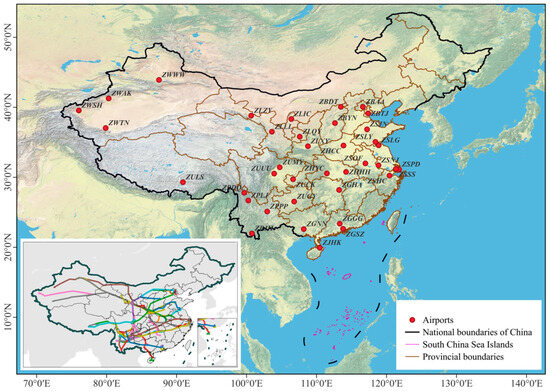
Figure 1.
Locations of selected airports and flight routes. The red points represent the airports. The 81 flight routes are shown in the sub-graph in the bottom left corner.
The selected airports are evenly distributed in five climate zones: a temperate monsoon climate (such as ZBAA in Beijing, ZHCC in Zhengzhou, and ZBTJ in Tianjin), temperate continental climate (such as ZWWW in Urumqi, ZWSH in Kashi, and ZWTN in Hetian), subtropical monsoon climate (such as ZGHA in Changsha, ZPPP in Kunming, ZUUU in Chengdu, and ZSPD in Shanghai), tropical monsoon climate (such as ZJHK in Zhuhai), and plateau mountainous climate (such as ZULS in Lhasa). The climate characteristics of the different climate zones have their own unique effects on the occurrence of aircraft bumpiness, and at the same time, flight routes crossing different climate zones are also prone to aircraft bumpiness caused by changes in climate. Establishing and comparing aircraft bumpiness prediction models using multiple algorithms for different airports and flight routes are necessary for evaluating and predicting aircraft bumpiness.
2.2. Artificial Intelligence Algorithms
In terms of aircraft turbulence prediction, some classic algorithms have been used by scholars to construct models, such as Random Forests (RFs) and Gradient-Boosted Regression Trees (GBRTs) explored by Domingo et al. [23]; Support Vector Machine (SVM) algorithms explored by Abernethy et al. [30] and Mizuno et al. [28]; and Multilayer Perceptron (MLP) networks explored by Oliveira et al. [31]. However, in the field of aviation meteorology, especially in the field of aircraft bumpiness, there are still many opportunities for classical methods to be fully tried and explored. This study constructed prediction models based on different algorithms and evaluated and compared their performances.
In addition to RF [32], SVM [33], and MLP that have been used by scholars, this study also used Classification and Regression Tree (CART), K-Nearest Neighbor (KNN), Least Angle Regression (LAR) [34], Ridge Regressor (RR), Stochastic Gradient Descent Regression (SGD) [35], Bayesian Ridge Regression (BRR) [36,37], Least Absolute Shrinkage and Selection Operator (LASSO) [38], Passive Aggressive Regression (PAR) [39], Random Sample Consensus Regression (RANSAC) [40], Huber Regression (HUB) [41,42], Elastic-Net Regression (ENR), Automatic Relevance Determination Regression (ARD) [43], Tweedie Regression (TWD) [44], Partial Least Squares Regression (PLS), Polynomial Regression (PLN), and Theil–Sen estimator (THS) algorithms [45,46].
- (1)
- Ridge Regression (RR)
Ridge regression solves some of the problems with ordinary least squares by imposing penalties on the size of coefficients. The ridge coefficient minimizes the sum of the squared residuals.
- (2)
- Least Absolute Shrinkage and Selection Operator (LASSO)
LASSO is a linear model for estimating sparse coefficients. It is very useful in certain situations as it tends to choose solutions with fewer parameter values, effectively reducing the number of variables on which a given solution depends. The minimum objective function is
- (3)
- Elastic-Net Regression (ENR)
ENR is a linear regression model trained with L1 and L2 priors as regularizers. This combination allows a sparse model to learn where few weights are non-zero like LASSO, while still maintaining Ridge’s regularization properties.
- (4)
- Bayesian Ridge Regression (BRR)
BRR implements a Bayesian setting to the regression model and adds an regularization term to the regression formula to avoid overfitting. The aim is to find a parameter distribution that minimizes the loss function (Equation (4)) with the Bayesian linear estimator defined in Equation (5).
Here, n and m are the sample dimension and capacity, respectively; is the n-dimensional random Gaussian variable following ; and is the n-dimensional vector of nonlinear functions. . Let be the th observed value, where is the random noise variable following . Then, follows a Gaussian distribution with mean . Equation (6) is the conditional probability density function of with the prior probability density of shown in Equation (7).
According to Bayesian rules,
Equation (9) shows the log posterior probability density function with a constant , which is in the form of a ridge regression equation. BRR introduces the regularization term to the optimization process using a Gaussian prior and thus, we can expect a more robust parameter estimation.
- (5)
- Random Sample Consensus Regression (RANSAC)
RANSAC builds a cost function and obtains the model parameters by maximizing it. The cost function is defined as follows:
where is the target parameter to optimize, is the known feature point set, and is the error function. The summation is over all feature points in the uniform set in the linear detection problem.
- (6)
- Huber Regression (HUB)
Huber loss is widely used when the dataset has plenty of outliers as it reduces the impact of the outliers compared to the loss. The Huber Regression estimator has been proven to be reliable for achieving a large sample asymptotic property by Huber and Peter [25]. The loss function of Huber Regression is defined as follows:
where
- (7)
- Automatic Relevance Determination Regression (ARD)
Denote the training dataset as , where represents the input value and represents the output values. We can obtain the following equation:
where is the noise variable following ~ N(0, ) with unknown . The conditional probability density function of is shown in Equation (14), which follows a Gaussian distribution:
The likelihood function of is a joint Gaussian density shown in the following given independence between each :
where weight parameter and is an matrix. Each follows the Gaussian distribution with mean 0 and variance . There is a hyperparameter that corresponds to the in each position. According to the Bayesian rule, could be derived as
where , , and . The maximum likelihood function is
where covariance matrix . Taking the partial derivatives of and and setting them equal to 0, we obtain the following two formulas:
Here, is the ith mean weight and is the ith main diagonal value of the covariance matrix. In each optimization iteration until convergence, m and C are updated with the posterior distribution.
- (8)
- Tweedie Regression (TWD)
Given a variance , we could obtain a Tweedie distribution family. Among the family, the most famous ones are normal distributions, Poisson distributions, Gamma distributions, and inverse Gaussian distributions with p = 0, 1, 2, 3, respectively. A generalized linear model with variables following a Tweedie distribution can be expressed as follows:
where and are the specification parameter and the discrete parameter for the Tweedie distribution. is the data consisting of q classification entries. is the weight parameter vector of order .
- (9)
- Classification and Regression Tree (CART)
Using to represent each training data point and y to represent the category to which the training data point belongs, let Ci be the fixed output value for each attribute xi. Equation (23) shows the regression tree model:
The model is looking for the best segmentation values for each , based on which, the data space could be divided into two regions: such that the square difference is minimized in the following equation.
- (10)
- K-Nearest Neighbor (KNN)
The KNN algorithm is quite intuitive. Suppose we have training dataset . For any test point x, the prediction of y is
where Nk(x) is the set of K-many samples nearest to x in the training dataset.
- (11)
- Least Angle Regression (LAR)
The least angel regression model solves an optimization problem as follows: are n independent samples and yi is the corresponding response. are the regression coefficients to be estimated and t is the constant constraint for regularization of the target function. The LAR algorithm minimizes the sum of the squared errors under the regularization constraint of the sum of .
- (12)
- Multi-Layer Perceptron (MLP)
MLP feeds the sum of the weighted input data to the feed-forward network through the activation function in each layer. The output ŷ is defined as
The weights ws are adjusted in every iteration to reduce the distance between the actual outputs and the predicted outputs with the following adjustment formula.
Here, wk is the updated weights after the kth learning cycle and xij represents the jth entry of input data xi. β indicates the learning rate. The k+1th parameter is calculated using wk plus an error value from decision (y–ŷ).
- (13)
- Support Vector Machine (SVM)
Denote the training dataset as , where each xi represents the input and yi represents the output. The SVM model constructs a hyperplane in the following:
where ω and b represent the coefficient vector and intercept of the hyperplane, respectively. The model tolerance points do not fall on the correct side of the hyperplane by setting a relaxation band (ξ, ξ*). The optimization problem is formed as follows:
Here, c acts as the penalty rate for points falling in the relaxation band and ε is the insensitive loss parameter. We could obtain an equivalent objective function with the help of the Lagrange multiplier, dual transformation, and nonlinear transformation.
Here, αi and αi* are the Lagrange multiplier. The high-dimensional computing problems in the SVM model could be solved by implementing the kernel function K(xi, yi). We show a linear kernel function in the following:
- (14)
- Random Forest (RF)
Random Forest is an ensemble learning algorithm that combines multiple decision trees to make predictions. It constructs a multitude of decision trees during training and makes predictions by averaging the outputs of each individual tree. Each tree in the random forest is built using a random subset of the training data and features, ensuring diversity and reducing overfitting.
- (15)
- Stochastic Gradient Descent Regression (SGD)
SGD is an optimization algorithm that is widely used in machine learning and deep learning. In a regression problem, SGD can be very effective in finding parameters that minimize the cost function, thus achieving data fitting or predictions. The basic idea of SGD is to randomly select one sample at a time to calculate the gradient and then update the model parameters. This allows SGD to converge faster because it only processes one sample at a time, rather than the entire dataset. However, this may also lead to fluctuations, as using only one sample at a time to update parameters may result in random fluctuations in the parameters.
- (16)
- Passive Aggressive Regression (PAR)
PAR is a binary machine learning method aimed at solving the problems of data sparsity and imbalance. Its core idea is that during the training process, for each sample, the model will attempt to predict its category and then adjust its impact on other samples based on the prediction results. Specifically, let us assume that our training set consists of a series of samples, and for each sample, we have a label y indicating the category it belongs to (for example, 0 or 1). During the training process, we first initialize a weight vector w, and for each sample, we calculate the predicted value (where x is the feature vector of the sample) and then update w according to the following formula:
where is a hyperparameter that controls the learning rate. This update rule results in a greater weight adjustment for samples with an incorrect classification. In this way, in subsequent predictions, the model will pay greater attention to those misclassified examples. Therefore, this method is a passive and aggressive approach that adjusts its own behavior to combat data imbalance without direct confrontation.
- (17)
- Partial Least Squares Regression (PLS)
PLS is a statistical method where the basic idea is to find a linear regression model by projecting the predicted and observed variables into a new space. This method is related to principal component regression, but it is not a hyperplane for finding the maximum variance between the response variable and the independent variable. Because both data X and Y are projected into a new space, the PLS series of methods are called bilinear factor models. When Y is classified data, this method is called “Partial Least Squares Discriminant Analysis (PLS-DA)”.
The details of the BRR, TWD, ARD, HUB, SVM, RANSAC, LAR, MLP, KNN, and CART algorithms were taken from our previous research [26,27]. The following will provide the details for the PLN and THS algorithms that were not covered in previous research. PLN-based models use a regression method that approximates measured points by increasing the higher-order term of the independent variable. It can handle a considerable number of classes of nonlinear problems and plays an important role in regression analysis. Because any function can be piecewise approximated by polynomials, it should be noted that the choice of the order of the polynomial to use for regression depends on the specific problem and data. If the relationship between them is nonlinear, then we may need to use polynomial regression for the analysis. However, as the order of the polynomial increases, there may be overfitting issues, where the model performs very well on the training set but poorly on the test set. Therefore, it is necessary to make appropriate adjustments and verifications when selecting the polynomial degree to balance the complexity of the model and the fitting effect.
The THS is a robust statistical method used to estimate the linear trends (slopes and intercepts) of a dataset. The THS first calculates the slopes between all point pairs in the dataset and then selects the median of these slopes as the final estimation value. By using the median instead of the average to estimate the slope, the THS has strong robustness to outliers in the data, effectively weakening the impact of these extreme points on the estimation results. Its advantages are as follows: It can effectively resist the interference of outliers in the data, making the estimation results more reliable; no special assumptions or distribution assumptions need to be made on the data, so it is suitable for various types of data; and there is no need to preprocess or convert the data, and raw data are directly used for estimation.
The above machine learning algorithms used in this research all rely on Python programming and its algorithm libraries.
3. Results
3.1. Monthly Characteristics of Different Aircraft Bumpiness Levels
From the approach areas of all the airports, the distribution range of EDR values was the largest in April 2020, and the largest EDR representing the strongest aircraft bumpiness also appeared in April 2020 (Figure 2a). In January, in 2020 and 2021, the distribution range of the EDR values was the smallest. The median EDR from March to June was also higher than that in January and February. From all the samples, the distribution pattern of the EDRs in each month was similar, that is, the distribution around the median was relatively concentrated, and the upper and lower distributions were relatively uniform. Severe aircraft bumpiness (EDR ≥ 0.7) over the airport approach area occurred less frequently in February and June 2020, especially in June (Figure 2b). Due to severe bumpiness being an extreme event in aircraft bumpiness, the distribution shape of the EDR varied from month to month, and the median values of the EDR also varied from month to month. Overall, the median of the EDRs was relatively small in the severe bumpiness sub-graph, especially in April 2020 and February 2021. In January 2020, March 2020, and May 2020, there were relatively serious turbulence events, with EDR values above 0.78. Compared to severe aircraft bumpiness, the monthly distributions of the EDR for moderate (0.4 ≤ EDR < 0.7) and mild (0.1 ≤ EDR < 0.4) aircraft bumpiness were relatively similar, and the images were also relatively regular (Figure 2c,d). The distributions of moderate aircraft bumpiness EDRs were relatively lower, indicating that the overall degree of moderate turbulence was relatively mild. However, the overall distributions of mild aircraft bumpiness tended to have larger EDR values, indicating that it was closer to the critical transition to moderate turbulence. The distributions of moderate aircraft bumpiness EDRs were relatively lower, indicating that the overall degree of moderate turbulence was relatively mild. The overall distribution of mild aircraft bumpiness tended to have larger EDR values. Although the EDRs of moderate and mild aircraft bumpiness were closer to the critical threshold for distinguishing between the two, moderate turbulence was closer to the critical threshold from the shape of its distribution.
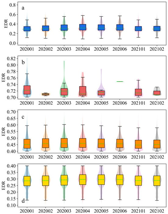
Figure 2.
Distribution characteristics of EDR values for different aircraft bumpiness levels in each month at all selected airport approach areas. (a–d) Distribution of all, severe, moderate, and mild aircraft bumpiness samples in their respective months. The green dashed line represents the median of the sample. The 25th and 75th percentiles are the bottom and top boundaries of the box.
Compared to the EDR distributions in the airport approach areas, the shapes of the EDRs on the flight routes were relatively different (Figure 3). From the distribution of all the samples, the upper limit of the EDRs on the flight routes did not differ significantly between months, while smaller EDR values appeared in February 2020 and February 2021 (Figure 3a). Similar to the situation in the approach area, there was also no severe aircraft bumpiness on the flight routes in February and June 2020, indicating that there were indeed fewer severe aircraft bumpiness occurrences in these two months (Figure 3b). The routes in January and March 2020 produced a few of the highest EDR values, namely, more severe aircraft bumpiness. The distribution of EDR values in February 2021 was relatively concentrated, which is different from the bottled or conical distributions in other months. The EDR distribution shapes of moderate aircraft bumpiness in each month were generally similar, showing a conical shape with a sharp top and a wide bottom, and the median EDR in each month was also basically the same (Figure 3c). In the mild aircraft bumpiness pattern, the median EDR from April to June 2020 was higher than in other months.
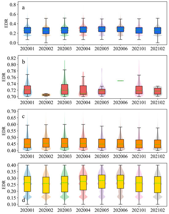
Figure 3.
Distribution characteristics of EDR values for different aircraft bumpiness levels in each month on all selected flight routes. (a–d) Distribution of all, severe, moderate, and mild aircraft bumpiness samples in their respective months. The green dashed line represents the median of the sample. The 25th and 75th percentiles are the bottom and top boundaries of the box.
3.2. Intra-Day Characteristics of Different Aircraft Bumpiness Levels
Aircraft bumpiness was mainly concentrated between 0:00 a.m. and 17:00 p.m. over the airport approach areas (Figure 4). The distribution of severe aircraft bumpiness was more concentrated than that of moderate and mild bumpiness and mainly occurred during the time period from 3:00 a.m. to 10:00 a.m. (Figure 4a). Severe aircraft bumpiness occurred more frequently in the early morning of January, especially between 5:00 a.m. and 6:00 a.m. The main occurrence period of moderate aircraft bumpiness was from 3:00 a.m. to 11:00 a.m., especially in the early morning (4:00 a.m. to 7:00 a.m.) in April and May 2020 (Figure 4b). The main distribution period of mild aircraft bumpiness was similar to that of moderate bumpiness, both from 4:00 a.m. to 7:00 a.m. (Figure 4c). There were more occurrences of various levels of aircraft bumpiness in the early morning in January 2020. Overall, the intra-day bumpiness distribution of flight route turbulence was similar to that of the approach areas.
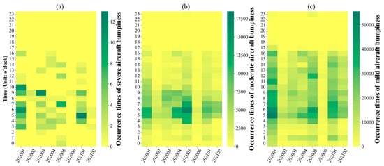
Figure 4.
Occurrence times of different aircraft bumpiness levels within each hour over airport approach areas. The horizontal axis represents the month and the vertical axis represents the hours from 0:00 to 23:00 during the day. (a–c) Number of occurrences of severe, moderate, and mild turbulence, respectively.
3.3. The Aircraft Flight State when Bumpiness Occurs
Over the airport approach areas, the aircraft bumpiness mainly occurred when the CAS was between 120 and 160 knots; in particular, mild aircraft bumpiness was more concentrated in this CAS range (Figure 5a). The state of the left and right angles of attack during aircraft bumpiness was basically the same, that is, bumpiness mainly occurred in the AOAL and AOAR range of −5 to 0 degrees, and mainly consisted of mild bumpiness (Figure 5b,c). When the aircraft pitching angle was 2 degrees, severe, moderate, and mild aircraft bumpiness were all highly concentrated (Figure 5d). In addition, the number of occurrences of bumpiness decreased from 2 to 5 and −3 degrees, and the level of bumpiness also decreased. The relationship graph between EDR and the roll was the most symmetrical (Figure 5e). When severe, moderate, and mild bumpiness occurred, the roll was mainly at 0 degrees and appeared symmetrically in a small amount within the range of plus or minus 25 degrees. Although there was no change in vertical velocity during most turbulence events, in a few cases, various types of bumpiness occurred in the IVV range of 0 to −10 feet/min (Figure 5f). This indicates that the aircraft was mainly in a descent state when it encountered aircraft bumpiness. The relationships between bumpiness and CAS and TAS were basically the same, as both CAS and TAS are elements of aircraft perception of wind speed, and the two are closely related (Figure 5a,g). The Mach provided a rough understanding of the speed of the aircraft, so the graphs of EDR vs. Mach were similar to those of EDR vs. CAS, showing that the larger the value, the more severe the aircraft bumpiness was (Figure 5h). At Mach values in the range of 0.65–0.78, aircraft bumpiness became more concentrated. Different wind speeds have different impacts on aircraft bumpiness, and the correlation between the two was very high (Figure 5i).
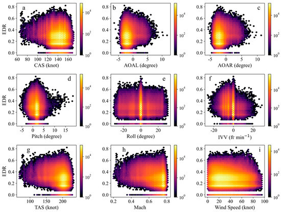
Figure 5.
The relationship between aircraft bumpiness and aircraft flight status over the airport approach areas.
On the flight routes, the relationships between bumpiness and two airspeeds were also generally similar (Figure 6a,g). Mild aircraft bumpiness was mainly concentrated in the CAS range of 70 to 155 knots (Figure 6a). Although the relationships between aircraft bumpiness on the routes and the left and right angles of attack were similar, the distributions on the routes were different from those over the approach area (Figure 6b,c). The relationships between the left and right angles of attack and aircraft bumpiness on the routes were more symmetrical with a center at 0 degrees, unlike in the approach areas where the hotspots were mainly concentrated in the range of −5 to 0 degrees (Figure 5b,c and Figure 6b,c). This observation may be because the aircraft mainly descends in the approach areas and there were more cases where the angle of attack was negative, while on the route, there was a balance between scenarios where the angle of attack of the aircraft was positive and those where it was negative. The aircraft bumpiness occurred within the symmetrical range of pitch values centered around 2 degrees, but the center of symmetry was not as obvious as in the approach areas (Figure 6d). The relationship curve between EDR and the roll on the routes was also symmetrical (Figure 6e). On the routes, aircraft bumpiness was still concentrated where the IVV was negative (i.e., during the descent of the aircraft) and was more pronounced than in the approach areas (Figure 6f). Unlike in the approach areas, the larger the Mach number, the more severe the bumpiness was. On the routes, there was mild aircraft bumpiness at different Mach numbers. Moderate aircraft bumpiness occurred more frequently when the Mach was slightly greater than 0.2 (Figure 6h). The aircraft bumpiness on the routes was most concentrated when the wind speed ranged from 0 to 40 knots (Figure 6i). Moderate and severe aircraft bumpiness mainly occurred at wind speeds of 0–30 knots.
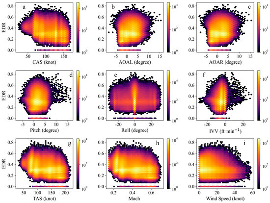
Figure 6.
The relationship between aircraft bumpiness and aircraft flight status on the flight routes.
3.4. Model Training and Validation
3.4.1. Aircraft Bumpiness Prediction Model for the Airport Approach Areas
The elements listed in Table 1 from the QAR data for 2020 and 2021 were used to construct a five-second EDR prediction model over the airport approach areas for the next 5 min, 10 min, and 20 min. The 2020 data were used to train the model, and the 2021 data were used for validation. Due to space limitations, both the prediction model for the approach areas in this section and for the air routes in the next section are presented in the training period diagram. Due to space limitations, the training period diagram for the prediction model for the approach areas in this section and the air routes in the next section are not shown.
The correlation coefficients between the predicted and observed EDRs for the next 5 min at each airport using the various methods were below 0.8 (Figure 7). This indicates that the performances of the models were not very good. From the standard deviation ratio between the predicted and observed values, the dispersion of the EDR predictions at most airports was smaller than that of the observed values. Under the KNN-based model, the ratios of the two at each airport were distributed around 1, which means that the dispersion between the predicted and observed values was relatively close. The HUB-, LAR-, PLN-, and RR-based models performed the worst in predicting aircraft bumpiness in the approach areas (Figure 7 and Figure 8). The performances of the ARD-, PLS-, ENR-, CART-, PAR-, RF-, SGD-, and TWD-based models were relatively good, but the prediction results of the models were generally smaller than the observed values.
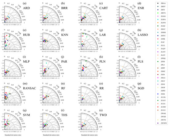
Figure 7.
Taylor diagram showing a comparison of the predicted and observed EDRs every 5 s for the next 5 min in the testing period over the approach areas. The diagram shows the correlation (the arc coordinate) and the ratio of the standard deviation between the predicted and observed values every 5 s (abscissa and ordinate). The subgraphs a-s represent the EDR simulation results of each of the 19 algorithm models.
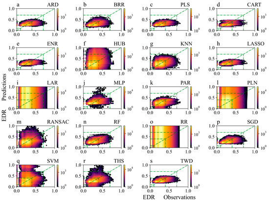
Figure 8.
Comparison of the observed and predicted EDRs for the next 5 min in the testing period over the approach areas.
The predicted results of the various models in the next 10 min were similar to the distributions in the next 5 min (Figures S1 and S2). Compared to the predicted results for the next 5 and 10 min of aircraft bumpiness, the predicted performance for the next 20 min was worse (Figure 9 and Figure 10). Compared to the values for the next 5 and 10 min, the correlation coefficient between the predicted and observed values for the next 20 min was smaller. In addition, the standard deviation ratio between the predicted and observed EDRs for the next 20 min was larger, which means that the difference in dispersion between the two sets of values was greater. However, compared to the next 5 min, the forecast results for the next 20 min using the SVM- and THS-based models improved. The HUB-, LAR-, PLN-, and RR-based models still performed the worst for the next 20 min forecast. Overall, the models performed best in predicting mild aircraft bumpiness, with the models generally having predicted values lower than the observed values. The aircraft bumpiness prediction models performed best over the approach areas of ZBDT in Datong, ZULS in Lhasa, ZPPP in Kunming, and ZLQY in Qingyang. As the prediction time increased, the prediction effect for ZULS decreased by the largest degree.
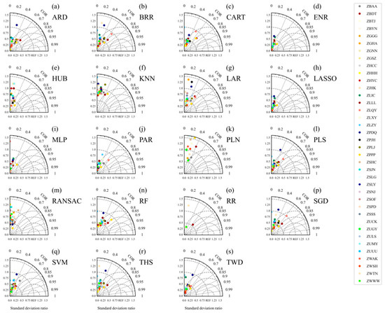
Figure 9.
Same as Figure 7 except for the next 20 min over the approach areas.
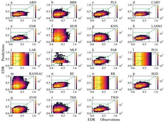
Figure 10.
Same as Figure 8 except for the next 20 min over the approach areas.
3.4.2. Aircraft Bumpiness Prediction Model for the Flight Routes
The QAR data elements used in the prediction model for air route aircraft bumpiness were the same as those used for the approach areas. At the same time, model training was conducted using the 2020 data, and model validation was conducted using the 2021 data. Compared to the QAR data in the approach areas, the data on the flight routes extended over a longer period of time, so aircraft bumpiness prediction models for the next 5 min, 10 min, 20 min, and 30 min were constructed for the flight routes.
Similar to the approach area scenario, the performances of the HUB-, LAR-, PLN-, and RR-based models were also very poor (Figure 11 and Figure 12). The distribution of the prediction results obtained by the KNN-based model was the closest to that of the observed values. The prediction results of the models with better performances, such as the PLS-, ENR-, and RF-based models, were generally smaller than the observed values. The performances of the models for the next 10 min and the next 20 min were similar to the performance for the next 5 min, but the effect deteriorated as the prediction time increased. Compared to the prediction for the next 5 min, the ENR-, LASSO-, MLP-, PAR-, and TWD-based models showed the most obvious decline in performance for the next 30 min (Figure 13 and Figure 14). In general, the prediction performances of the different models were roughly similar but decreased in the same time period. The aircraft bumpiness prediction model for the next 5 min performed best on the ZLLL-ZLQY (Lanzhou–Qingyang), ZPNL-ZPPP (Ninglang–Kunming), and ZLLL-ZBDT (Lanzhou–Datong) routes. As the forecast time increased, in addition to ZLLL-ZBDT, the prediction model for the next 30 min also performed better on the ZPZT-ZPJH (Zhaotong–Xishuangbanna) and ZPDQ-ZULS (Diqing–Lhasa) routes.
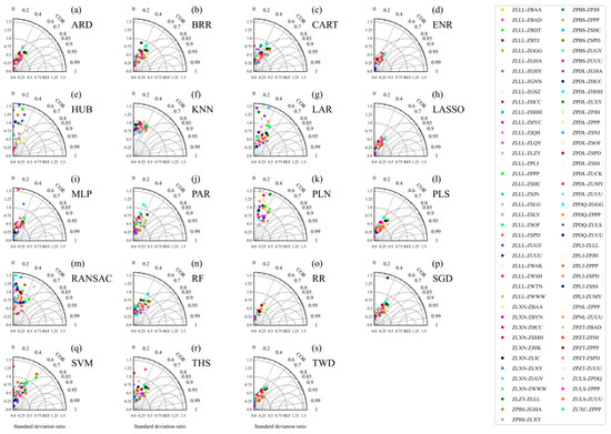
Figure 11.
Taylor diagram showing a comparison of the predicted and observed EDRs every 5 s for the next 5 min in the testing period on the flight routes. The diagram shows the correlation (the arc coordinate) and the ratio of the standard deviation between the predicted and observed every 5 s (abscissa and ordinate).
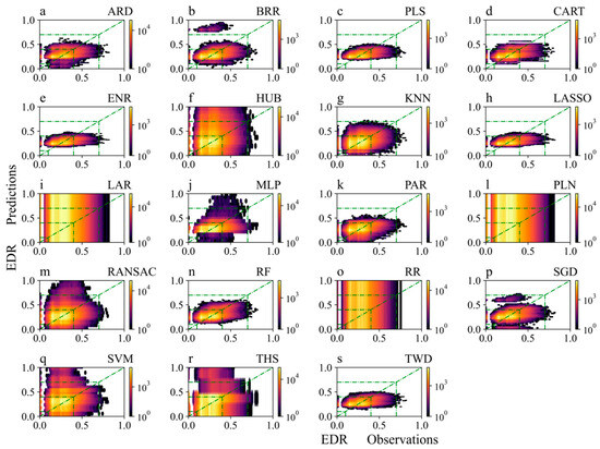
Figure 12.
Comparison of the observed and predicted EDRs for the next 5 min in the testing period on the flight routes.
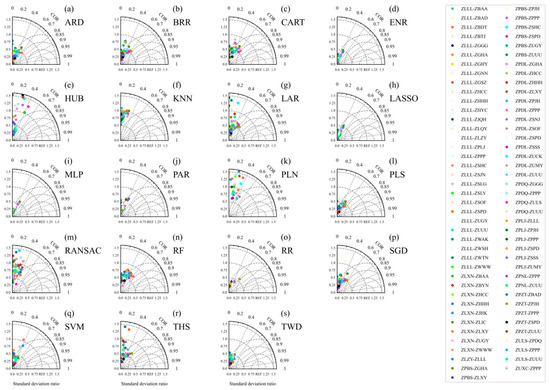
Figure 13.
Same as Figure 11 except for the next 30 min on the flight routes.
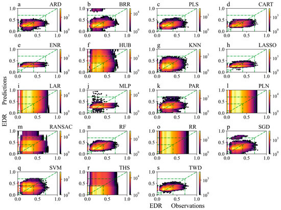
Figure 14.
Same as Figure 12 except for the next 30 min on the flight routes.
4. Discussion
For the monthly distribution, Jin et al. [47] pointed out that the occurrence frequency of aircraft bumpiness is the highest in the winter and lowest in the summer. The reason for this is that the summer jet is relatively weak, and radar and other equipment can predict the thunderstorms that lead to aircraft bumpiness in the summer, in advance, so that this type of weather can be avoided through flight adjustments and other means. This is different from the increased summer aircraft bumpiness compared to that in January and February observed in our study. This discrepancy could be due to the different research periods; the previous scholars used data from 2016, while we used data from 2020 to 2021. Alternatively, it could be related to the study area; the previous research focused on the Beijing region, and we used more samples of airports and routes.
LASSO- and TWD-based models exhibit good performance in handling prediction problems with high-dimensional features and/or nonlinear relationships. The LASSO-based model uses a linear regression method with its main advantage being the ability to perform feature selection. This can help reduce the impact of noise features and improve the predictive performance of the model when processing high-dimensional data. In addition, LASSO-based models can also handle some features with multicollinearity, so it has certain advantages when dealing with problems such as aircraft turbulence prediction. TWD-based models are suitable for handling data with variance homogeneity issues. When dealing with nonlinear relationships, TWD-based models can provide more accurate model fitting. For example, in aircraft bumpiness prediction, the relationship between the speed of the aircraft and the degree of bumpiness may not be a simple linear relationship but rather a non-linear relationship. In this case, a TWD-based model may provide more accurate predictions than traditional linear regression methods.
The ENR-based model performed well in the approach areas and routes, which seems to be related to the fact that the features are all elements in the QAR data. If certain features are related (multicollinearity), an ENR-based model is the best choice because it is unlikely to set certain parameters to zero. The RF-based model can provide a helpful guide to initial predictor selection but can be biased and does not expose correlations between variables. The RF-based model did show a better performance than the logistic regression models for this problem, perhaps because it makes better use of predictors that are not monotonically related to the prediction. It may be that some of the predictor variables could be transformed or combined to make them more effective in a simpler model, which would be preferable from the standpoint of computational intensity in a real-time system [22].
The areas where the models performed best in this study were concentrated in western China, especially flight routes in the southwestern plateau region. Fang L. [48] pointed out that the impact of aircraft bumpiness on China’s plateau routes is more severe, and the frequency of aircraft bumpiness in the approach areas is higher. They found that the summer aircraft bumpiness was induced by convection, while winter aircraft bumpiness was induced by jet streams and mountain waves. Wang S. [49] found that aircraft bumpiness is more likely to occur in areas with complex terrain, and the bumpiness in the approach areas is even more severe. Xu et al. [50] also found that there is a high incidence area of high-altitude turbulence in northern Sichuan and eastern Tibet. Li C. [51] identified a certain connection between aircraft bumpiness characteristics and airport and route traffic. For example, aircraft bumpiness often occurs in areas with high flight flow, dense waypoints, and busy routes. At the same time, there are also frequent aircraft bumpiness events near minor route distribution areas, indicating that there is a high possibility of frequent weather events causing aircraft bumpiness in these areas. This needs to be further analyzed in conjunction with the meteorological background in future studies.
5. Conclusions
In this study, the monthly and intra-day characteristics of different aircraft bumpiness levels were analyzed, and aircraft bumpiness models were constructed based on 19 artificial intelligence algorithms for 38 airport approach areas and 81 flight routes in China based on the QAR data from the first half of 2020 and the first two months of 2021. The main results are as follows:
- i.
- Severe aircraft bumpiness over the airport approach areas occurred less frequently in February and June 2020, especially in June. For mild aircraft bumpiness, the median EDR from April to June 2020 was higher than in the other months.
- ii.
- Aircraft bumpiness was mainly concentrated between 0:00 a.m. and 17:00 p.m. Severe aircraft bumpiness occurred more frequently in the early morning of January, especially between 5:00 a.m. and 6:00 a.m. The moderate bumpiness occurred from 3:00 a.m. to 11:00 a.m., especially in the early morning (4:00 a.m. to 7:00 a.m.) in April and May 2020.
- iii.
- The relationships between the left and right angles of attack and aircraft bumpiness on the route were more symmetrical with a center at 0 degrees, unlike in the approach areas where the hotspots were mainly concentrated in the range of −5 to 0 degrees. Unlike in the approach areas, the larger the Mach, the more severe the bumpiness was. On the routes, when the Mach number was slightly greater than 0.2, moderate aircraft bumpiness occurred more frequently.
- iv.
- The performances of the ARD-, PLS-, ENR-, CART-, PAR-, RF-, SGD-, and TWD-based models were relatively good, while the performances of the HUB-, LAR-, PLN-, and RR-based models were very poor. The aircraft bumpiness prediction models performed best over the approach areas of ZBDT in Datong, ZULS in Lhasa, ZPPP in Kunming, and ZLQY in Qingyang. As the prediction time increased, the prediction effect for ZULS decreased the most severely. The aircraft bumpiness prediction model on flight routes for the next 5 min performed best for the ZLLL-ZLQY (Lanzhou–Qingyang), ZPNL-ZPPP (Ninglang–Kunming), and ZLLL-ZBDT (Lanzhou–Datong) routes. As the forecast time increased, in addition to ZLLL-ZBDT, the prediction model for the next 30 min also performed better for the ZPZT-ZPJH (Zhaotong–Xishuangbanna) and ZPDQ-ZULS (Diqing–Lhasa) routes.
Supplementary Materials
The following supporting information can be downloaded at: https://www.mdpi.com/article/10.3390/atmos14111704/s1, Figure S1: Taylor diagram presents a comparison of the every 5 s predicted and observed EDR for the next 10 min in the testing period over the approach areas. The diagram shows the correlation (the arc coordinate) and ratio of the standard deviation between the every 5 s predicted and observed (Abscissa and ordinate); Figure S2: Comparison of the EDR observed and predicted for the next 10 min in the testing period over the approach areas; Figure S3: Taylor diagram presents a comparison of the every 5 s predicted and observed EDR for the next 10 min in the testing period on the flight routes. The diagram shows the correlation (the arc coordinate) and ratio of the standard deviation between the every 5 s predicted and observed (Abscissa and or-dinate); Figure S4: Comparison of the EDR observed and predicted for the next 10 min in the testing period on the flight routes; Figure S5: Same as Figure S3 except for the next 20 min on the flight routes; Figure S6: Same as Figure S4 except for the next 20 min on the flight routes.
Author Contributions
Writing—original draft, J.D.; writing—review and editing, J.D and Y. T.; supervision, G.Z. and S.W.; data curation, S.W., B.X., R.J., T.Y., Y.C., Y.H., Z.L., X.L., R.Y. and K.W.; methodology, J.D.; visualization, J.D. and Y.T. All authors have read and agreed to the published version of the manuscript.
Funding
This research was funded by the National Key Research and Development Program of China (2020YFB1600103), the Innovation Fund Youth Project of PMSC (Y2022012), and the National Natural Science Foundation of China (grant 12201062).
Institutional Review Board Statement
Not applicable.
Informed Consent Statement
Not applicable.
Data Availability Statement
Data available on request due to restrictions (privacy). The data presented in this study are available on request from the corresponding author. The data are not publicly available due to the aviation information and flight data are sourced from the corresponding author Zhang Guoping’s partner, the Civil Aviation Administration of China which we have already expressed our gratitude and explanation in the Acknowledgments section. These materials are relatively sensitive and are not publicly disclosed, and there are no websites or links to obtain the information.
Acknowledgments
A special thanks to the Civil Aviation Administration of China for providing flight data. We thank each of the authors for their contributions to this study. At the same time, we would like to thank each editor and reviewer for their constructive comments and revisions to the manuscript.
Conflicts of Interest
The authors declare that they have no conflict of interest.
References
- Bradshaw, P. An Introduction to Turbulence and Its Measurement; Pergamon Press: Oxford, UK, 1971. [Google Scholar]
- Launder, B.E.; Spalding, D.B. Mathematical Models of Turbulence; Von Karman Institute for Fluid Dynamics: Sint-Genesius-Rode, Belgium, 1972. [Google Scholar]
- Argyropoulos, C.D.; Markatos, N.C. Recent advances on the numerical modelling of turbulent flows. Appl. Math. Model. 2015, 39, 693–732. [Google Scholar] [CrossRef]
- Huang, R.; Sun, H.; Wu, C.; Wang, C.; Lu, B. Estimating Eddy Dissipation Rate with QAR Flight Big Data. Appl. Sci. 2019, 9, 5192. [Google Scholar] [CrossRef]
- Gao, Z.; Wang, H.; Qi, K.; Xiang, Z.; Wang, D. Acceleration-Based In Situ Eddy Dissipation Rate Estimation with Flight Data. Atmosphere 2020, 11, 1247. [Google Scholar] [CrossRef]
- Yanovsky, F.; Prokopenko, I.; Prokopenko, K.; Russchenberg, H.; Ligthart, L. Radar estimation of turbulence eddy dissipation rate in rain. In Proceedings of the IEEE International Geoscience and Remote Sensing Symposium—IGARSS 2002, Toronto, ON, Canada, 24–28 June 2002. [Google Scholar]
- Chan, P.W. LIDAR-based turbulence intensity calculation using glide-path scans of the Doppler LIght Detection and Ranging (LIDAR) systems at the Hong Kong International Airport and comparison with flight data and a turbulence alerting system. Meteorol. Z. 2010, 19, 549–563. [Google Scholar] [CrossRef]
- Hon, K.K.; Chan, P.W. Application of LIDAR-derived eddy dissipation rate profiles in low-level wind shear and turbulence alerts at Hong Kong International Airport. Meteorol. Appl. 2014, 21, 74–85. [Google Scholar] [CrossRef]
- Borque, P.; Luke, E.; Kollias, P. On the unified estimation of turbulence eddy dissipation rate using Doppler cloud radars and lidars. J. Geophys. Res. Atmos. 2016, 121, 5972–5989. [Google Scholar] [CrossRef]
- Yang, S.; Petersen, G.N.; Von Löwis, S.; Preißler, J.; Finger, D.C. Determination of eddy dissipation rate by Doppler lidar in Reykjavik, Iceland. Meteorol. Appl. 2020, 27, e1951. [Google Scholar] [CrossRef]
- Kim, J.-H.; Park, J.-R.; Kim, S.-H.; Kim, J.; Lee, E.; Baek, S.; Lee, G. A Detection of Convectively Induced Turbulence Using in Situ Aircraft and Radar Spectral Width Data. Remote Sens. 2021, 13, 726. [Google Scholar] [CrossRef]
- Emara, M.; Santos, M.D.; Chartier, N.; Ackley, J.; Mavris, D.N. Machine learning enabled turbulence prediction using flight data for safety analysis. In Proceedings of the 32nd Congress of the International Council of the Aeronautical Sciences, Shanghai, China, 6–10 September 2021. [Google Scholar]
- Cai, X.; Wan, Z.; Wu, W.; Yang, B.; Yi, Z. An Ensemble Prediction Method of Aviation Turbulence Based on the Energy Dissipation Rate. Chin. J. Atmos. Sci. 2022, 47, 1085–1098. [Google Scholar] [CrossRef]
- Sharman, R.D.; Pearson, J.M. Prediction of Energy Dissipation Rates for Aviation Turbulence. Part I: Forecasting Nonconvective Turbulence. J. Appl. Meteorol. Clim. 2017, 56, 317–337. [Google Scholar] [CrossRef]
- Pearson, J.M.; Sharman, R.D. Prediction of Energy Dissipation Rates for Aviation Turbulence. Part II: Nowcasting Convective and Nonconvective Turbulence. J. Appl. Meteorol. Clim. 2017, 56, 339–351. [Google Scholar] [CrossRef]
- Muñoz-Esparza, D.; Sharman, R.; Sauer, J.; Kosović, B. Toward Low-Level Turbulence Forecasting at Eddy-Resolving Scales. Geophys. Res. Lett. 2018, 45, 8655–8664. [Google Scholar] [CrossRef]
- Kim, J.-H.; Sharman, R.; Strahan, M.; Scheck, J.W.; Bartholomew, C.; Cheung, J.C.H.; Buchanan, P.; Gait, N. Improvements in Nonconvective Aviation Turbulence Prediction for the World Area Forecast System. Bull. Am. Meteorol. Soc. 2018, 99, 2295–2311. [Google Scholar] [CrossRef]
- Lee, D.-B.; Chun, H.-Y.; Kim, S.-H.; Sharman, R.D.; Kim, J.-H. Development and Evaluation of Global Korean Aviation Turbulence Forecast Systems Based on an Operational Numerical Weather Prediction Model and In Situ Flight Turbulence Observation Data. Weather Forecast 2022, 37, 371–392. [Google Scholar] [CrossRef]
- Chen, H.; Pang, L.; Wanyan, X.; Liu, S.; Fang, Y.; Tao, D. Effects of Air Route Alternation and Display Design on an Operator’s Situation Awareness, Task Performance and Mental Workload in Simulated Flight Tasks. Appl. Sci. 2021, 11, 5745. [Google Scholar] [CrossRef]
- Shu, Y.; Zhu, Y.; Xu, F.; Gan, L.; Lee, P.T.-W.; Yin, J.; Chen, J. Path planning for ships assisted by the icebreaker in ice-covered waters in the Northern Sea Route based on optimal control. Ocean Eng. 2023, 267, 113182. [Google Scholar] [CrossRef]
- Chen, X.; Wang, Z.; Hua, Q.; Shang, W.-L.; Luo, Q.; Yu, K. AI-Empowered Speed Extraction via Port-Like Videos for Vehicular Trajectory Analysis. IEEE Trans. Intell. Transp. Syst. 2022, 24, 4541–4552. [Google Scholar] [CrossRef]
- Williams, J.K. Using random forests to diagnose aviation turbulence. Mach. Learn. 2014, 95, 51–70. [Google Scholar] [CrossRef]
- Muñoz-Esparza, D.; Sharman, R.D.; Deierling, W. Aviation Turbulence Forecasting at Upper Levels with Machine Learning Techniques Based on Regression Trees. J. Appl. Meteorol. Clim. 2020, 59, 1883–1899. [Google Scholar] [CrossRef]
- Sridhar, B. Applications of Machine Learning Techniques to Aviation Operations: Promises and Challenges. In Proceedings of the 2020 International Conference on Artificial Intelligence and Data Analytics for Air Transportation (AIDA-AT), Singapore, 3–4 February 2020; pp. 1–12. [Google Scholar] [CrossRef]
- Cordeiro, F.M.; França, G.B.; Neto, F.L.d.A.; Gultepe, I. Visibility and Ceiling Nowcasting Using Artificial Intelligence Techniques for Aviation Applications. Atmosphere 2021, 12, 1657. [Google Scholar] [CrossRef]
- Ding, J.; Zhang, G.; Wang, S.; Xue, B.; Yang, J.; Gao, J.; Wang, K.; Jiang, R.; Zhu, X. Forecast of Hourly Airport Visibility Based on Artificial Intelligence Methods. Atmosphere 2022, 13, 75. [Google Scholar] [CrossRef]
- Ding, J.; Zhang, G.; Yang, J.; Wang, S.; Xue, B.; Du, X.; Tian, Y.; Wang, K.; Jiang, R.; Gao, J. Temporal and Spatial Characteristics of Meteorological Elements in the Vertical Direction at Airports and Hourly Airport Visibility Prediction by Artificial Intelligence Methods. Sustainability 2022, 14, 12213. [Google Scholar] [CrossRef]
- Mizuno, S.; Ohba, H.; Ito, K. Machine learning-based turbulence-risk prediction method for the safe operation of aircrafts. J. Big Data 2022, 9, 29. [Google Scholar] [CrossRef]
- Wang, L.; Wu, C.; Sun, R. An analysis of flight Quick Access Recorder (QAR) data and its applications in preventing landing incidents. Reliab. Eng. Syst. Saf. 2014, 127, 86–96. [Google Scholar] [CrossRef]
- Abernethy, J.A.; Sharman, R.; Bradley, E. Application of artificial intelligence to operational real-time clear-air turbulence prediction. In Proceedings of the Twenty-Third AAAI Conference on Artificial Intelligence—AAAI 2008, Chicago, IL, USA, 13–17 July 2008. [Google Scholar]
- Oliveira, M.M.; Mayor, G.S.; Macedo, J.P.; Bidinotto, J.H. Neural networks to classify atmospheric turbulence from flight test data: An optimization of input parameters for a generic model. J. Braz. Soc. Mech. Sci. Eng. 2022, 44, 82. [Google Scholar] [CrossRef]
- Breiman, L. Random forests. Mach. Learn. 2001, 45, 5–32. [Google Scholar] [CrossRef]
- Cristianini, N.; Taylor, J.S. An Introduction to Support Vector Machines and Other Kernel-Based Learning Methods; University Press: Cambridge, UK, 2000. [Google Scholar]
- Avila, J.; Hauck, T. Least angle regression. Ann. Stat. 2004, 32, 407–499. [Google Scholar] [CrossRef]
- Robbins, H.; Monro, S. A Stochastic Approximation Method. Ann. Math. Stat. 1951, 22, 400–407. [Google Scholar] [CrossRef]
- MacKay, D.J.C. Bayesian Interpolation. Neural Comput. 1992, 4, 415–447. [Google Scholar] [CrossRef]
- Tipping, M.E. Sparse bayesian learning and the relevance vector machine. J. Mach. Learn. Res. 2001, 1, 211–244. [Google Scholar] [CrossRef]
- Tibshirani, R. Regression shrinkage and selection via the lasso. J. R. Stat. Soc. Ser. B Methodol. 1996, 58, 267–288. [Google Scholar] [CrossRef]
- Crammer, K.; Dekel, O.; Keshet, J.; Shalev-Shwartz, S.; Singer, Y.; Warmuth, M.K. Online passive-aggressive algorithms. J. Mach. Learn. Res. 2006, 7, 551–585. [Google Scholar] [CrossRef]
- Fischler, M.A.; Bolles, R.C. Random sample consensus: A paradigm for model fitting with applications to image analysis and automated cartography. Commun. ACM 1981, 24, 619–638. [Google Scholar] [CrossRef]
- Huber, P.J. A Robust Version of the Probability Ratio Test. Ann. Math. Stat. 1965, 36, 1753–1758. [Google Scholar] [CrossRef]
- Huber, P.J. Robust Regression: Asymptotics, Conjectures and Monte Carlo. Ann. Stat. 1973, 1, 799–881. [Google Scholar] [CrossRef]
- Durbin, R.; Willshaw, D. An analogue approach to the travelling salesman problem using an elastic net method. Nature 1987, 326, 689–691. [Google Scholar] [CrossRef]
- Mackay, D.J.C. Bayesian Non-Linear Modeling for the Energy Prediction Competition. In Proceedings of the 1994 American Society of Heating, Refrigerating, and Air Conditioning Engineers (ASHRAE), Orlando, FL, USA, 25–29 June 1994; Volume 100. [Google Scholar]
- Thiel, H. A Rank-Invariant Method of Linear and Polynomial Regression Analysis. Proc. Proc. Kon. Ned. Akad. Wet. Ser. A Math. Sci. 1950, 53, 386–392. [Google Scholar]
- Sen, P.K. Estimates of the regression coefficient based on Kendall’s Tau. J. Am. Stat. Assoc. 1968, 63, 1379–1389. [Google Scholar] [CrossRef]
- Jin, C.; Guo, W.; Gan, L.; Wang, C. Statistics and possible sources of low-level turbulence below 3000 m and its meteorological condition in beijing. J. Meteorol. Environ. 2019, 35, 18–26. [Google Scholar]
- Fang, L. Research on the Characteristics and Causes of High Altitude Aircraft Bump Based on Aircraft Detection Data; Civil Aviation Flight University of China: Deyang, China, 2022. [Google Scholar] [CrossRef]
- Wang, S. Research on the Influence of Terrain on Aircraft Bumping; Civil Aviation Flight University of China: Deyang, China, 2022. [Google Scholar] [CrossRef]
- Xu, J.; Wang, D.; Gong, Y.; Duan, Y. Quantitative diagnostic and distribution characteristics of aircraft turbulence in China. J. Chengdu Univ. Inf. Technol. 2018, 33, 704–712. [Google Scholar] [CrossRef]
- Li, C. Research on the Main Temporal and Spatial Distribution Characteristics of Aircraft Turbulence in China; Civil Aviation Flight University of China: Deyang, China, 2018. (In Chinese) [Google Scholar]
Disclaimer/Publisher’s Note: The statements, opinions and data contained in all publications are solely those of the individual author(s) and contributor(s) and not of MDPI and/or the editor(s). MDPI and/or the editor(s) disclaim responsibility for any injury to people or property resulting from any ideas, methods, instructions or products referred to in the content. |
© 2023 by the authors. Licensee MDPI, Basel, Switzerland. This article is an open access article distributed under the terms and conditions of the Creative Commons Attribution (CC BY) license (https://creativecommons.org/licenses/by/4.0/).