Article

Coherent Backscattering by Large Ice Crystals of Irregular Shapes in Cirrus Clouds

1
V.E. Zuev Institute of Atmospheric Optics SB RAS, Academician Zuev Sq. 1, 634055 Tomsk, Russia
2
Radiophysics Department, National Research Tomsk State University, Lenina Str. 36, 634050 Tomsk, Russia
3
Key Laboratory of Atmospheric Optics, Anhui Institute of Optics and Fine Mechanics, Hefei Institutes of Physical Science, Chinese Academy of Sciences, Hefei 230031, China
*
Author to whom correspondence should be addressed.
Atmosphere 2022, 13(8), 1279; https://doi.org/10.3390/atmos13081279
Submission received: 22 July 2022 / Revised: 10 August 2022 / Accepted: 10 August 2022 / Published: 12 August 2022
(This article belongs to the Special Issue Properties of Cirrus Cloud by Lidars: Observation and Theory)

Abstract

:
All elements of the scattering matrix have been numerically studied for particles of irregular shapes whose size is much larger than incident wavelength. The calculations are performed in the physical optics approximation for a particle size of 20 μm at a wavelength of 0.532 μm. Here the scattered intensity reveals the backscattering coherent peak. It is shown that the polarization elements of the matrix reveal the surges within the backscattering peak. The angular width of the surges does not practically depend on particle shape, but depends on the particle size. It is shown that these surges are created by interference between the conjugate scattered waves propagating in the inverse directions. The results obtained are of interest for interpretation of lidar measurements in cirrus clouds.

1. Introduction

The problem of light scattering by particles of irregular shapes whose sizes are much larger than an incident wavelength is a challenging problem in optics. These particles occur in the atmosphere as aggregates of ice crystals in cirrus clouds [1], and as the large-scale particles of the atmospheric dust [2], etc. Such particles are also ubiquitous in the Universe. For example, they are a part of the powder-like substance covering the surfaces of solar system objects [3]. In particular, they are a part of the regolith covering the Moon.
The theoretical solution of the light scattering problem by the large irregular particles has not yet been obtained. Here, the well-known methods for numerical solution of the Maxwell equations [4] like the finite-difference time-domain method (FDTDM) or the discrete dipole approximation (DDA) are not effective because the solution demands extreme computer resources at a large magnitude of the size parameter x = πD/λ, where D is the particle size and λ is the wavelength. At present, the numerical solutions can be obtained only at about x < 100. The geometric-optics approximation for such particles is not applicable too, since the geometrical optics do not take into account the interference phenomena that are essential near the backward scattering direction.
The physical optics approximation that combines the principles of geometrical and wave optics is most appropriate for solving the problem. There are many versions of the physical optics approximation. In particular, about 30 years ago, P. Yang and K-N. Liou developed such a method for solving the problem of light scattering by ice crystals of cirrus clouds [5,6]. Later, their algorithm was generalized by K. Masuda [7]. Independent algorithms were carried out also by K. Muinonen [8], H. Okamoto [9,10], L. Bi [11], H. Ishimoto [12], E. Hesse [13], and others. However, their calculations were acceptable for large scattering angles. It was shown that the case of near backward scattering, which was important for lidar studies, demanded some improved algorithms.
The authors of this paper have developed the algorithm that is applicable to backscattering by large particles. This algorithm is described in detail in a recent book [14]. Some calculations obtained with this algorithm have been already verified by comparisons with the lidar measurements [15,16]. It is worthwhile to note that there are other numerical methods solving the problem of light scattering by large particles of irregular shapes [17,18,19,20].
It should be noted that astrophysicists studying light scattering on the abovementioned powder-like surfaces had discovered two optical phenomena about 100 years ago. The first phenomenon is the essential increase of the scattered intensity at the backward scattering direction. It was caused by the opposition effect or backscattering peak. The second phenomenon, named the negative polarization, can be described as the following: the degree of linear polarization of the scattered light in the case of unpolarized incident light becomes negative and reveals a surge near the backward direction. There are numerous theories trying to explain these phenomena [21,22,23,24,25,26,27,28,29,30,31,32,33,34,35].
It is important that both phenomenon were obtained recently in the numerical solution of the problem of light scattering by one randomly-oriented particle of irregular shape at x < 150 where the discontinuous Galerkin time-domain method (DGTDM) was used [19,20]. We suggest that the reason that the same phenomena, i.e., the backscattering peak and negative polarization, have been observed for such different scattering objects is because the light scattered in both cases can be treated as a sum of photons with random trajectories. For a powder-like scattering medium, the appearance of the random photon trajectories is obvious, whereas a single randomly-oriented particle produces the random photon trajectories because of multiple internal reflections from an irregular boundary of the randomly-oriented particle.
In this paper, we show that the scattering matrix for the large particles of irregular shapes, as a function of scattering angles, reveals some surges in the vicinity of the backward direction for all elements of the scattering matrix analogously to the surge known for the negative polarization phenomena. These surges have been explained by interference among the waves constituting the scattered light.

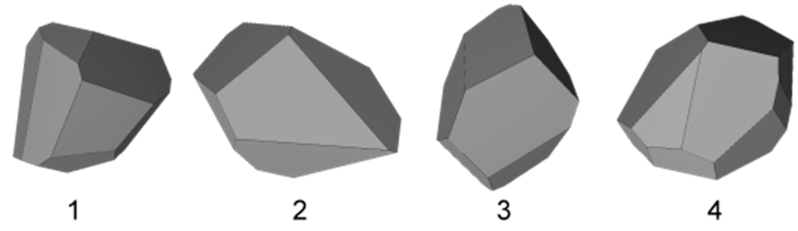
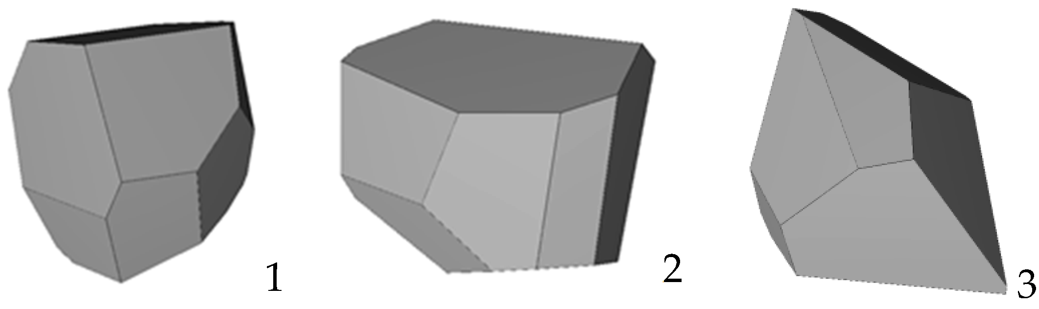
2. Scattering Matrix for the Models of Ice Crystal Aggregates

We model the shape of ice crystal aggregates as a set of random polyhedrons shown in Figure 1.
The scattered light is described by the Stokes vector I = (I, Q, U, V). The incident light I0 is transformed into the scattered light I by the equation [4]:
I ( θ , φ ) = Z ( θ , φ ) I 0
Here θ and φ are the zenith and azimuthal scattering angles, respectively, that are determined by the given incident n0 and scattering n directions, and Z is the so-called phase matrix 4 × 4. In the case of randomly oriented particles, the phase matrix reduces to the scattering matrix F ( θ ) that has the following view.
F ( θ ) = ( < F 11 > < F 12 > 0 0 < F 12 > < F 22 > 0 0 0 0 < F 33 > < F 34 > 0 0 < F 34 > < F 44 > )
In astrophysics, the incident light is usually unpolarized
I 0 = ( 1 , 0 , 0 , 0 )
and intensity of the scattered light is measured with a polarizer oriented either perpendicular I or parallel I | | to the scattering plane. In this case, the quantity
p ( θ ) = I I | | I + I | |
is called the degree of linear polarization. In notation of the scattering matrix, we get
p ( θ ) = < F 12 ( θ ) > < F 11 ( θ ) >

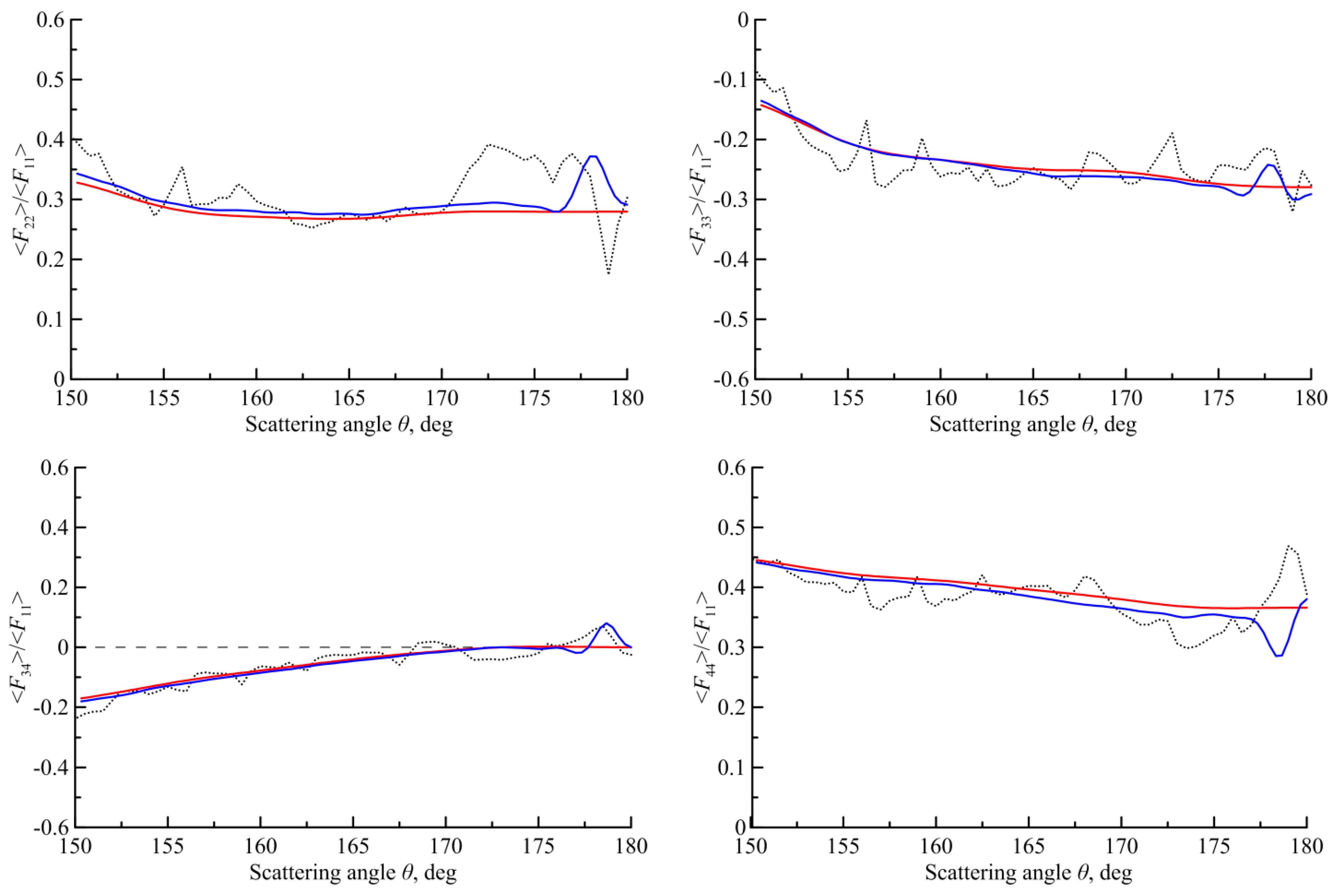
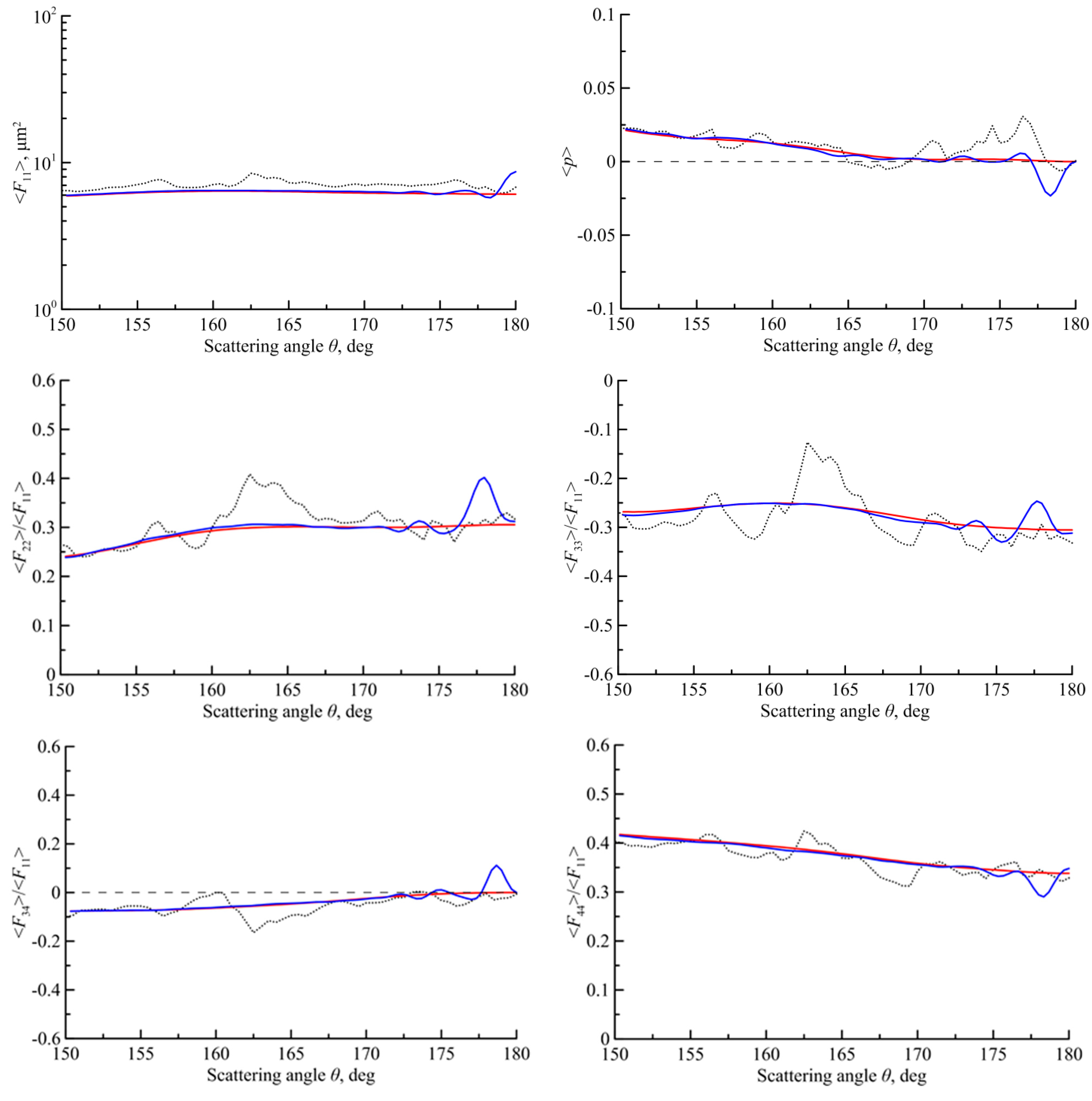
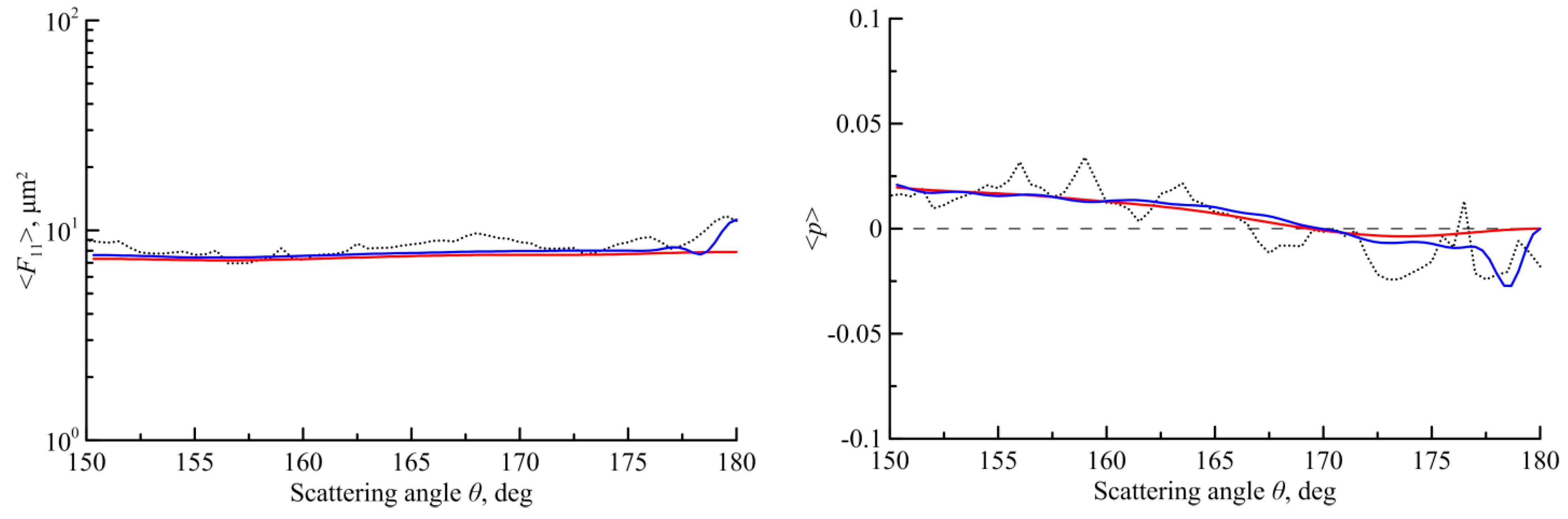
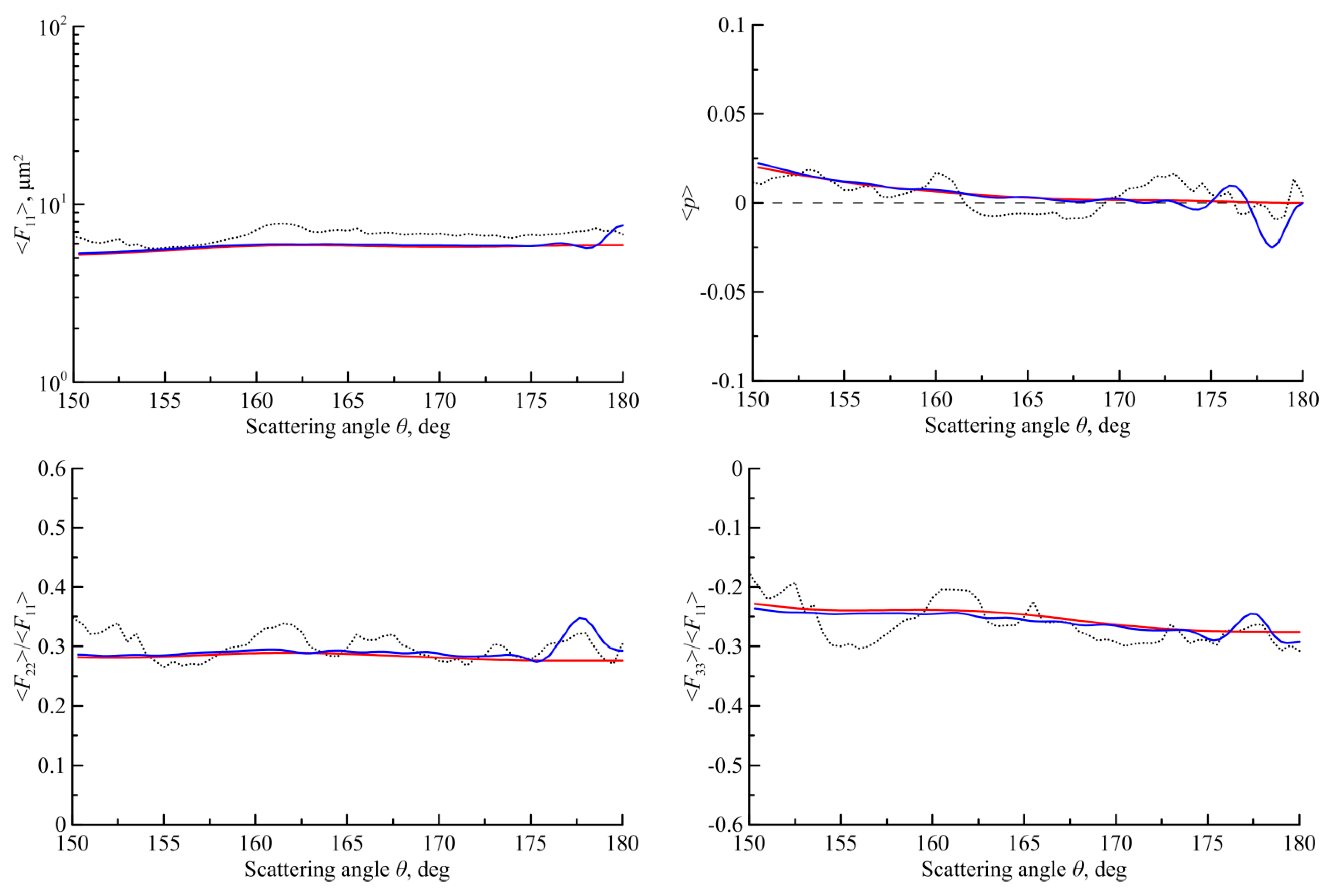
3. The Scattering Matrixes Calculated in the Physical-Optics Approximation

We have calculated the scattering matrixes of Equation (2) for the particle shapes of Figure 1 using our physical-optics method [14]. In the physical-optics method, the light inside a polyhedral particle of a large size is described by geometrical optics. As a result, the light inside the particle becomes a superposition of many plane-parallel beams with various transversal size and shapes propagating in different directions. After refraction by an exit facet, any beam is transformed into a diverging spherical wave according to the Fraunhofer diffraction. As a result, the scattered wave in the wave zone of the particle is a superposition of a large number of diverging spherical waves that are summarized by our code. The code also averages the scattered light over a random particle orientation; this procedure is denoted by the brackets < … >.
In this paper, all numerical calculations are performed for the randomly oriented particles with Dmax = 20 μm where Dmax is the maximum distance between two points on the particle surface. The wavelength was equal to 0.532 µm, and the refractive index was assumed as 1.3116.
Figure 2, Figure 3 and Figure 4 show the scattering matrixes of Equation (2) obtained for three model shapes of Figure 1. Note that our code allows us to calculate the scattered light in three regimes: (1) geometrical optics, (2) incoherent summation (only diffraction), and (3) coherent summation (diffraction + interference). The geometrical optics regime is most crude. Here, any beam after refraction by an exit facet propagates straightforward to the scattering direction sphere ( θ , φ ) , producing only a point on the sphere. The incoherent summation regime is more realistic. In this case, the Fraunhofer diffraction transforms the geometrical optics dot into a diffraction spot on the scattering direction sphere. Finally, the coherent summation regime is most exact. Here, the interference among the scattered waves has been taken into account that it is performed inside the diffraction spots. Three regimes have been shown by different curves in Figure 2, Figure 3 and Figure 4. The truncated curves correspond to the geometrical optics regime, and the solid blue and red curves are taken for the coherent and incoherent summations, respectively.
In Figure 2, Figure 3 and Figure 4, we see that the results obtained in the regime of geometrical optics (truncated curves) are quite different from those obtained in other regimes. This fact proves that the geometrical optics approximation does not describe this scattering problem adequately.
Let us comment on the results obtained in Figure 2, Figure 3 and Figure 4. The first element of the scattering matrix < F 11 > is the differential cross-section of the particle. Recently, we showed [36] that the differential cross-section for large particles of irregular shapes creates the coherent backscattering peak that was well known for random scattering media [21]. We see that the coherent peak appears in Figure 2, Figure 3 and Figure 4 for all particle models in the regime of coherent summation (blue curves).
As for the other elements of the scattering matrix in Figure 2, Figure 3 and Figure 4, we obtain the following general conclusions. All elements of the scattering matrices in the regime of coherent summation (blue curves) reveal some surges near the backward scattering direction. The angular widths of the surges are approximately the same; they are approximately equal to the width of the coherent backscattering peak fort the first element < F 11 > . In the regime of an incoherent summation (red curves), these surges disappear. This fact proves that any surges in the elements of the scattering matrix near the backward scattering direction have been caused by interference among significant amount of the backscattering waves. In the other words, these surges are the coherent backscattering effects like the well-known coherent backscattering peak [21].

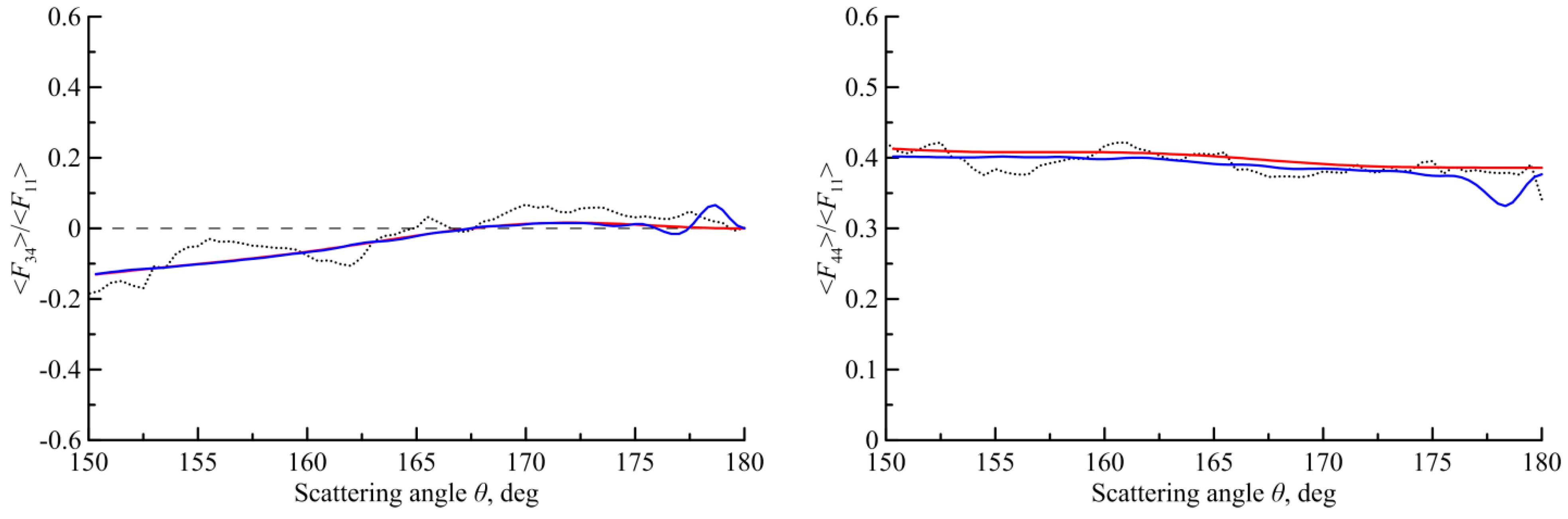
4. The Scattering Matrix for Other Size and Shapes of the Particles

Calculations of the scattering matrix for the large particles near the backward scattering direction demand considerable computer resources. Here, a great number of particle orientations should be taken to obtain a reliable solution. Therefore, there is some inconsistency between calculations obtained with different codes [35,36]. To support the results of the previous section, in this section we repeat the calculations for other particle shapes shown in Figure 5.
In Figure 6 the scattering matrix is obtained for two particle sizes: D = 5 µm (thin curves) and D = 20 µm (thick curves).
As seen in Figure 2, Figure 3, Figure 4 and Figure 6, the particle shapes change weakly the heights of the surges where the heights are varied up to 15%. However, the particle sizes impact on the polarization elements more essentially and leads to changes in the surge widths. In particular, the surge angular width is doubled if the particle size is decreased by half. This fact is well demonstrated in Figure 6 by the elements 12, 22 and 34, while the elements 33 and 44 are sensitive to particle shapes, too.

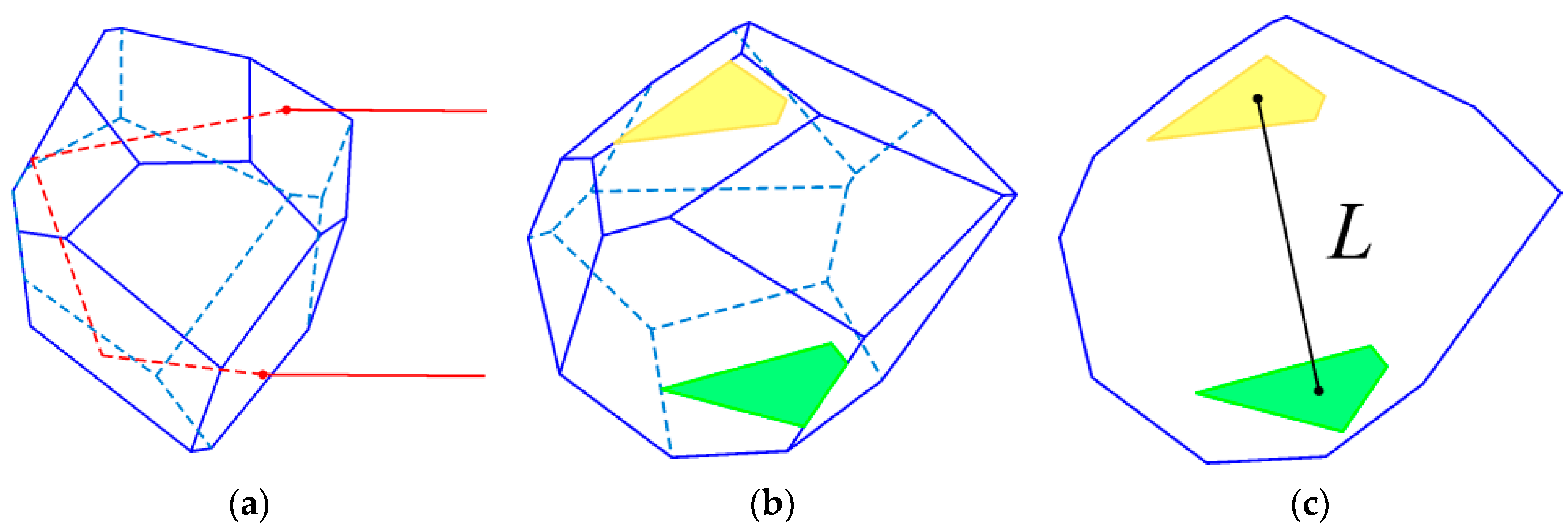
5. Grazing-Incidence Trajectories and the Backscattering Peak

It is important that in the case of a randomly-oriented faceted particle of convex shape, the photon trajectories producing the coherent backscattering are mainly reduced to the grazing-incidence trajectories. In the grazing-incidence trajectories, every reflection takes place at the angle close to the full internal reflection and, consequently, the energy of the beam after multiple reflections is almost saved. On the contrary, if a beam enters or leaves the particle near the center of the particle projection on the plane perpendicular to the incident direction, intensity of this beam strongly decreases because of the smaller reflection coefficient at the near normal reflection by facets.
In a grazing-incidence trajectory, the light travels predominantly along the particle surface and then leaves the particle after refraction by an exit facet that produces a beam outgoing near the particle edge. An example of such trajectories is depicted in Figure 7. The light travelling along this trajectory in the inverse direction creates analogously the outgoing beam of the similar shape and size near the opposite particle edge as shown in Figure 7a. Our calculation shows that transverse size of a grazing-incidence beam a is less than the particle diameter D. Consequently, such a pair of the beams leaves a particle near the opposite edges of a particle at the distance L between them, shown in Figure 7c. For brevity, we call them a pair of conjugate beams.
Figure 8 supports our suggestion that the grazing-incidence trajectories are dominant in backscattering by large, randomly-oriented particles. Here we summarized the intensities of the beams leaving the particle 3 of Figure 1 averaged over random orientations of the particle. The numerical calculations were carried out in the geometrical optics approximation where only the beams leaving the particle in the near zone with the scattering directions less than θ = 179° were taken into account. Figure 8 shows distributions of the intensity of the backscattered light over the particle projection on the plane perpendicular to the incident direction. We see that the outgoing intensity is not uniform; it is concentrated near the particle edge, especially for the trajectories with two internal reflections.
In the wave zone of the particle, the scattered field is a function of the scattering direction that can be approximately found as the 2D Fourier transform of the picture obtained on the plane perpendicular to the incident direction in Figure 7c. As a result, the coherent backscattering is seen in the narrow cone of the scattering angles Δ θ λ / L about the backward direction θ = 180°.

6. Interference of the Grazing-Incidence Beams

Consider the pair of plane-parallel beams of Figure 7 leaving the particle at a backward direction. In the wave zone of the particle, these beams produce two outgoing spherical waves that are added coherently in any scattering direction n = ( θ , φ ) , where θ and φ are the zenith and azimuthal angles, respectively, and θ = 180° is the exact backward direction.
Figure 9 and Figure 10 show the intensity M 11 ( n ) and the polarization element M 12 ( n ) calculated for the conjugate beams of Figure 7 for particle with Dmax = 20 μm.
Factually, Figure 9a corresponds to the Fraunhofer diffraction patterns of these two beams that are averaged between them. The angular width of the figure is Δ θ λ / a where a is the transverse size of the beams in Figure 7.
As for the coherent summation presented in Figure 10, we see practically the same patterns as in Figure 9, but these patterns are additionally cut with the interference fringes because of the interference between conjugate beams. In our case, these fringes appear as many straight stripes. These stripes are oriented perpendicular to the line L connecting the centers of the beam projections on the plane perpendicular to the incident direction shown in Figure 7c. Note that any stripe has its order. Thus, the zeroth-order stripe corresponds to the condition that the phase difference between the scattered beams on the scattering direction sphere is less than 2π, and so on. The angular width of one stripe in Figure 10 is equal to Δ θ λ / L . As a result, the number of stripes in Figure 10a cutting the diffraction pattern of Figure 9a is equal to about L/a.
The polarization element of the Mueller matrix M 12 ( n ) in Figure 10b should be nonzero within the same interference stripes as in Figure 10a. However, unlike the scattered intensity M 11 ( n ) in Figure 10a, the magnitudes of M 12 ( n ) in Figure 10b are sign alternating quantities. As a result, the zeroth-order stripe of Figure 10a has been transformed in Figure 10b into two oblate ovals touching at θ = 180°.
Figure 9 and Figure 10 are obtained for a fixed particle orientation shown in Figure 7, while we need to have the Mueller matrix averaged over random particle orientations. The procedure of averaging over particle orientations reduces to averaging over three Euler angles that includes also averaging over particle rotations around the incident direction. Let us denote a particle rotation over the incident direction by the angle α. It is the averaging over α that will be further considered in detail.
Assuming that the patterns of Figure 9 and Figure 10 are obtained at α = 0, it can be shown that at arbitrary α we obtain M 11 ( θ , φ ; α ) = M 11 ( θ , φ α ; α = 0 ) and M 12 ( θ , φ ; α ) = M 12 ( θ , φ α ; α = 0 ) , i.e., the elements M 11 and M 12 at the arbitrary turn α are equal to the same values at α = 0 but shifted azimuthally at φ α . Consequently, the average over α reduces to integration of Figure 10 over the azimuth angle φ . Any line φ = c o n s t in Figure 10 is called a meridian. Assume that the zeroth meridian φ = 0 goes perpendicular to the stripes and the meridian φ = π/2 goes along the zeroth interference stripe. Figure 11 presents the polarization along these two meridians.
The function M 12 ( θ , φ = 0 ) oscillates due interference between the beams with the angular widths of the stripes of about λ/L. Because of the constructive interference, the function M 12 ( θ , φ = 0 ) is positive. Another function M 12 ( θ , φ = π / 2 ) corresponds to the Fraunhofer diffraction of these beams in the perpendicular direction. The diffraction pattern is the peak with the angular width of λ/a. Since their sum at the exact backward direction should be zero M 12 ( π / 2 , φ = 0 ) + M 12 ( π / 2 , φ = π / 2 ) = 0 , the function M 12 ( θ , φ = π / 2 ) is negative along the meridian. The average of the functions < M 12 > = [ M 12 ( θ , φ = 0 ) + M 12 ( θ , φ = π / 2 ) ] / 2 is shown in Figure 11 by a black line. We see that the sum passes through a local minimum at the angle θ 0 = λ / 2 d . The green line in Figure 11 shows the element M 12 already numerically averaged over all meridians. We ascertain that the desired function < M 12 > passes its local minimum at the same point θ 0 = λ / 2 d . This fact proves that the physical mechanism providing appearance of the local minimum is the interference between pairs of conjugate beams. It is interesting that this point θ 0 = λ / 2 d is equal to a half of the angular width of the coherent backscattering peak for intensity of the scattered light.

7. Conclusions

1. In our previous paper [36], we demonstrated that, in the problem of light scattering by a large particle of irregular shape, the backscattered intensity revealed a coherent peak caused by interference of the waves propagating in the inverse directions. In this paper, we have demonstrated that all polarization elements of the scattering matrix reveal similar regularities; namely, the polarization elements create the surges within the coherent backscattering peak. These surges are the results of interference of the waves propagating in the inverse directions.
2. We have shown that the angular width of the surges does not practically depend on particle shape, but depends on particle size. In particular, particle shapes usually change the surge heights up to 10–15%, whereas a double particle size leads to a half angular width of the surges.
3. We have shown that the angular width of the surges is approximately equal to one-half of an angular width of the coherent backscattering peak.
The results of this paper could be used for interpretation of the data obtained from lidar soundings of cirrus clouds.

Author Contributions

Conceptualization, N.K., A.K., V.S., D.T., A.B. and Z.W.; methodology, N.K., A.K., V.S., D.T., A.B. and Z.W.; software, N.K., A.K., V.S. and D.T.; validation, N.K., A.K., A.B. and Z.W.; formal analysis, N.K., A.K. and A.B.; investigation, N.K., A.K., V.S., D.T., A.B. and Z.W.; resources, A.B. and Z.W.; data curation, N.K., V.S. and D.T.; writing—original draft preparation, A.B. and Z.W.; writing—review and editing, A.B. and Z.W.; visualization, N.K. and V.S.; supervision, A.B.; project administration, A.K.; funding acquisition, A.B. All authors have read and agreed to the published version of the manuscript.

Funding

The study was supported by the Russian Science Foundation, grant number 22-27-00282, https://rscf.ru/en/project/22-27-00282/ accessed on 15 April 2022.

Institutional Review Board Statement

Not applicable.

Informed Consent Statement

Not applicable.

Data Availability Statement

Not applicable.

Acknowledgments

Z.W. and A.B. thank the NSFC (41975038, 42111530028). A.K. thanks the CAS PIFI (2021VTA0009). Z.W. also thanks the CAS YIPA (Y2021113).

Conflicts of Interest

The authors declare no conflict of interest.

References

  1. Liou, K.-N.; Yang, P. Light Scattering by Ice Crystals. Fundamentals and Applications; Cambridge University Press: Cambridge, UK, 2016; p. 460. [Google Scholar]
  2. Tsekeri, A.; Amiridis, V.; Louridas, A.; Georgoussis, G.; Frendenthaler, V.; Metallinos, S.; Doxastakis, G.; Gasteiger, J.; Siomos, N.; Paschou, P.; et al. Polarization lidar for detecting dust orientation: System design and calibration. Atmos. Meas. Tech. 2021, 14, 7453–7474. [Google Scholar] [CrossRef]
  3. Mishchenko, M.I.; Rosenbush, V.K.; Kiselev, N.N.; Lupishko, D.F.; Tishkovets, V.P.; Kaydash, V.G.; Belskaya, I.N.; Efimov, Y.S.; Shakhovskoy, N.M. Polarimetric Remote Sensing of Solar System Objects; Akademperiodika: Kyiv, Ukrain, 2010; p. 291. [Google Scholar]
  4. Mishchenko, M.I.; Hovenier, J.W.; Travis, L.D. Light Scattering by Nonspherical Particles; Academic: San Diego, CA, USA, 2000; p. 720. [Google Scholar]
  5. Yang, P.; Liou, K.N. Light scattering by hexagonal ice crystals: Comparison of finite-difference time domain and geometric optics models. J. Opt. Soc. Am. 1995, A12, 162–176. [Google Scholar] [CrossRef]
  6. Yang, P.; Liou, K.N. Geometric-optics-integral-equation method for light scattering by nonspherical ice crystals. Appl. Opt. 1996, 35, 6568–6584. [Google Scholar] [CrossRef] [PubMed]
  7. Masuda, K.; Ishimoto, H.; Mano, Y. Efficient method of computing a geometric optics integral for light scattering by nonspherical particles. Pap. Meteorol. Geophys. 2012, 63, 15–19. [Google Scholar] [CrossRef]
  8. Muinonen, K. Scattering of light by crystals: A modified Kirchhoff approximation. Appl. Opt. 1989, 28, 3044–3050. [Google Scholar] [CrossRef]
  9. Iwasaki, S.; Okamoto, H. Analysis of the enhancement of backscattering by nonspherical particles with flat surfaces. Appl. Opt. 2001, 40, 6121–6129. [Google Scholar] [CrossRef] [PubMed]
  10. Sato, K.; Okamoto, H. Characterization of Z(e) and LDR of nonspherical and inhomogeneous ice particles for 95-GHz cloud radar: Its implication to microphysical retrievals. J. Geophys. Res. 2006, 111, D22213. [Google Scholar] [CrossRef]
  11. Bi, L.; Yang, P.; Kattawar, G.W.; Hu, Y.; Baum, B.A. Scattering and absorption of light by ice particles: Solution by a new physical-geometric optics hybrid method. J. Quant. Spectrosc. Radiat. Transf. 2011, 112, 1492–1508. [Google Scholar] [CrossRef]
  12. Baran, A.J.; Ishimoto, H.; Sourdeval, O.; Hesse, E.; Harlow, C. The applicability of physical optics in the millimetre and sub-millimetre spectral region. Part II: Application to a three-component model of ice cloud and its evaluation against the bulk single-scattering properties of various other aggregate models. J. Quant. Spectrosc. Radiat. Transf. 2018, 206, 83–100. [Google Scholar] [CrossRef]
  13. Hesse, E.; Taylor, L.; Collier, C.T.; Penttila, A.; Nousiainen, T.; Ulanowski, Z. Discussion of a physical optics method and its application to absorbing smooth and slightly rough hexagonal prisms. J. Quant. Spectrosc. Radiat. Transf. 2018, 218, 54–67. [Google Scholar] [CrossRef]
  14. Konoshonkin, A.V.; Borovoi, A.G.; Kustova, N.V.; Shishko, V.A.; Timofeev, D.N. Light Scattering by Atmospheric Ice Crystals within the Physical Optics Approximation; FIZMATLIT: Moscow, Russia, 2022; p. 384. (In Russian) [Google Scholar]
  15. Kokhanenko, G.P.; Balin, Y.S.; Klemasheva, M.G.; Nasonov, S.V.; Novoselov, M.M.; Penner, I.E.; Samoilova, S.V. Scanning Polarization Lidar LOSA-M3: Opportunity for Research of Crystalline Particle Orientation in the Clouds of Upper Layers. Atmos. Meas. Tech. 2020, 13, 1113–1127. [Google Scholar] [CrossRef]
  16. Reichardt, J.; Wandinger, U.; Klein, V.; Mattis, I.; Hilber, B.; Begbie, R. RAMSES: German Meteorological Service autonomous Raman lidar for water vapor, temperature, aerosol, and cloud measurements. Appl. Opt. 2012, 51, 8111–8131. [Google Scholar] [CrossRef] [PubMed]
  17. Zubko, E.; Shmirko, K.; Pavlov, A.; Sun, W.; Schuster, G.L.; Hu, Y.; Stamnes, S.; Omar, A.; Baize, R.R.; McCormick, M.P.; et al. Active remote sensing of atmospheric dust using relationships between their depolarization ratios and reflectivity. Opt. Lett. 2021, 46, 2352–2355. [Google Scholar] [CrossRef]
  18. Zubko, E.; Weinbergern, A.J.; Zubko, N.; Shkuratov, Y.; Videen, G. Umov effect in single-scattering dust particles: Effect of irregular shape. Opt. Lett. 2017, 42, 1962–1965. [Google Scholar] [CrossRef] [PubMed]
  19. Grynko, Y.; Shkuratov, Y.; Forstner, J. Intensity surge and negative polarization of light from compact irregular particles. Opt. Lett. 2018, 43, 3562–3565. [Google Scholar] [CrossRef]
  20. Grynko, Y.; Shkuratov, Y.; Forstner, J. Light scattering by irregular particles much larger than the wavelength with wavelength-scale surface roughness. Opt. Lett. 2016, 41, 3491–3494. [Google Scholar] [CrossRef] [PubMed]
  21. Mishchenko, M.I.; Travis, L.D.; Lacis, A.A. Multiple Scattering of Light by Particles: Radiative Transfer and Coherent Backscattering; Cambridge University Press: Cambridge, UK, 2006; p. 478. [Google Scholar]
  22. Mishchenko, M.I.; Dlugach, J.M.; Liu, L.; Rosenbush, V.K.; Kiselev, N.N.; Shkuratov, Y.G. Direct solutions of the Maxwell equations explain opposition phenomena observed for high-albedo solar system objects. Astrophys. J. Lett. 2009, 705, L118–L122. [Google Scholar] [CrossRef]
  23. Muinonen, K. Coherent backscattering of light by complex random media of spherical scatterers: Numerical solution. Waves Random Media 2004, 14, 365–388. [Google Scholar] [CrossRef]
  24. Ozrin, V.D. Exact solution for coherent backscattering of polarized light from a random medium of Rayleigh scatterers. Waves Random Media 1992, 2, 141–164. [Google Scholar] [CrossRef]
  25. Penttilä, A.; Lumme, K.; Hadamcik, E.; Levasseur-Regourd, A.-C. Statistical analysis of asteroidal and cometary polarization phase curves. Astron. Astrophys. 2005, 432, 1081–1090. [Google Scholar] [CrossRef]
  26. Petrova, E.V.; Jockers, K.; Kiselev, N.N. Light scattering by aggregates with sizescomparable to the wavelength: An application to cometary dust. Icarus 2000, 148, 526–536. [Google Scholar] [CrossRef]
  27. Petrova, E.V.; Tishkovets, V.P.; Jockers, K. Polarization of light scattered by Solar system bodies and the aggregate model of dust particles. Sol. Syst. Res. 2004, 38, 354–371. [Google Scholar] [CrossRef]
  28. Rosenbush, V.K. The phase-angle and longitude dependence of polarization for Callisto. Icarus 2002, 159, 145–155. [Google Scholar] [CrossRef]
  29. Shkuratov, Y.; Ovcharenko, A.; Zubko, E.; Volten, H.; Muñoz, O.; Videen, G. The negative polarization of light scattered from particulate surfaces and of independently scattering particles. J. Quant. Spectrosc. Radiat. Transf. 2004, 88, 267–284. [Google Scholar] [CrossRef]
  30. Shkuratov, Y.; Bondarenko, S.; Kaydash, V.; Videen, G.; Muños, O.; Volten, H. Photometry and polarimetry of particulate surfaces and aerosol particles over a wide range of phase angles. J. Quant. Spectrosc. Radiat. Transf. 2007, 106, 487–508. [Google Scholar] [CrossRef]
  31. Wang, Z.; Cui, S.; Zhang, Z.; Yang, J.; Gao, H.; Zhang, F. Theoretical extension of universal forward and backward Monte Carlo radiative transfer modeling for passive and active polarization observation simulations. J. Quant. Spectrosc. Radiat. Transf. 2019, 235, 81–94. [Google Scholar] [CrossRef]
  32. Shkuratov, Y.G.; Muinonen, K.; Bowell, E.; Lumme, K.; Peltoniemi, J.I.; Kreslavsky, M.A.; Stankevich, D.G.; Tishkovetz, V.P.; Opanasenko, N.V.; Melkumova, L.Y. A critical review of theoretical models of negatively polarized light scattered by atmosphereless solar system bodies. Earth Moon Planets 1994, 65, 201–246. [Google Scholar] [CrossRef]
  33. Mishchenko, M.I.; Luck, J.-M.; Nieuwenhuizen, T.M. Full angular profile of the coherent polarization opposition effect. J. Opt. Soc. Am. A 2000, 17, 888–891. [Google Scholar] [CrossRef]
  34. Videen, G.; Muinonen, K.; Lumme, K. Coherence, power laws, and the negative polarization surge. Appl. Opt. 2003, 42, 3647–3652. [Google Scholar] [CrossRef]
  35. Zhou, C.; Yang, P. Backscattering peak of ice cloud particles. Opt. Express 2015, 23, 11995–12003. [Google Scholar] [CrossRef]
  36. Shishko, V.A.; Konoshonkin, A.V.; Kustova, N.V.; Timofeev, D.N.; Borovoi, A.G. Coherent and incoherent backscattering by a single large particle of irregular shape. Opt. Express 2019, 27, 32984–32993. [Google Scholar] [CrossRef]
Figure 1. Shapes of the model polyhedron particles.
Atmosphere 13 01279 g001
Figure 2. The scattering matrix for the shape 1 of Figure 1.
Atmosphere 13 01279 g002
Figure 3. The scattering matrix for the shape 2 of Figure 1.
Atmosphere 13 01279 g003aAtmosphere 13 01279 g003b
Figure 4. The scattering matrix for the shape 3 of Figure 1.
Atmosphere 13 01279 g004aAtmosphere 13 01279 g004b
Figure 5. Other particle shapes used in calculations.
Atmosphere 13 01279 g005
Figure 6. The scattering matrix for particles of Figure 5 with two sizes.
Atmosphere 13 01279 g006
Figure 7. Conjugate pair of backscattering beams with grazing-incidence trajectories (a). Shapes of the beams on the exit facets (b) and on a plane perpendicular to the incident direction (c). The line L connects the centers of the beam projections.
Atmosphere 13 01279 g007
Figure 8. Distribution of the backscattered intensity over the particle projection obtained in the geometrical optics approximation for the beam trajectories with three (a) and four (b) internal reflections/refraction events averaged for two Euler angles of particle orientations. Here (c) is the average over random orientation.
Atmosphere 13 01279 g008
Figure 9. Backscattered intensity M 11 ( n ) (a) and polarization element M 12 ( n ) (b) for two beams of Figure 7 at incoherent summation. The figure centers are the exact backward direction θ = 180°, the blue color in (b) corresponds to negative quantities.
Atmosphere 13 01279 g009
Figure 10. The same as in Figure 9 at coherent summation.
Atmosphere 13 01279 g010
Figure 11. Element M 12 ( θ , φ ) of Figure 10b plotted for: (a) two perpendicular meridians φ = 0 (red) and φ = π / 2 (blue); (b) their average (black), and (c) averaged over φ (green).
Atmosphere 13 01279 g011
Publisher’s Note: MDPI stays neutral with regard to jurisdictional claims in published maps and institutional affiliations.

