1. Introduction
Unmanned aerial vehicles (UAVs) have been used in atmospheric research since the 1970s [
1]. Compared to fixed-wing types, multi-copter UAVs provide high flexibility in operations as they are easier to handle and do not require a runway for taking off and landing. Therefore, multicopters have recently been intensively used for a broad range of applications, from measuring meteorological parameters (such as wind vector [
2,
3], temperature and humidity [
4,
5,
6], and radiation [
7]) to measuring the concentration of trace gases (e.g., methane [
6,
8,
9]) and aerosol [
10,
11,
12,
13] in the atmospheric boundary layer. In contrast to classical sampling techniques performed on the ground and at tall towers, UAVs offer high flexibility in the selection of the sampling location and altitude. They fill the gap of sampling the atmospheric boundary layer with high temporal and spatial resolution at scales of typically up to 1 km altitude and to a few kilometers horizontally (e.g., [
14]). As a result, it is possible to study spatio-temporal mixing processes, necessary to derive accurate models for distribution dynamics. In applications of UAVs for atmospheric measurements, it is possible either to take air samples for analysis after flights (e.g., [
15]), to connect the UAV-based sampling to the analysis instruments on the ground (e.g., [
8]), or to perform in-situ measurements on the UAV with optical, chemical or other methods (e.g., [
11,
12,
13]).
In atmospheric measurements, there are some cases where a large absorption path between light source and detector is desired for better results than can be achieved by one UAV. One particular method for the concentration measurement is based on the absorption of electromagnetic radiation, e.g., laser absorption spectroscopy, which requires a large absorption path in the range of several tens of meters for good accuracy [
16]. Stereophotogrammetric methods, specially with non-static objects in the scene, also require the deployment of two cameras at rather large distances in the range of several meters to hundreds of meters.
However, current UAV-based solutions for atmospheric measurements mostly focus on using a single UAV which is difficult to deal with in the aforementioned cases. For example, the length and weight of the air sampling lines or tubes are limited by the capacity (in terms of the size and the maximum payload weight) of the UAV [
6]. In addition, when instantaneous onboard analysis is desired, the capacity of a single UAV will also require analyzers to be small and lightweight for the integration.
Instead of using a single UAV, the use of distributed UAVs in formation flight can overcome significant technical challenges and financial limitations, which arise from the use of manned aircraft with more space for instrumentation. The distribution of sensors and payloads among several UAVs allows higher coverage area, redundancy, cost efficiency, and even realizability, enabling new applications that would not be achievable with a single UAV or even manned aircraft. In the typical application of laser spectroscopy for determining the concentration of a certain molecule in the atmosphere (e.g., methane), the distribution of the laser source and detector unit between two UAVs means a flexible and less constrained sampling path and hence better measurement quality while avoiding all listed limitations of the single UAV based approach.
One key challenge of such a formation flight is the relative position estimation and control in a wind-perturbed outdoor environment. While several studies tackled the algorithmic issues related to system modeling, state estimation, and control, there are few published works dealing with the challenges of a hardware implementation in wind-perturbed environments. Rekleitis et al. [
17] studied quadrotor formation flying using angles-only navigation extracted from a monocular camera and two colored markers installed collinearly on the mutually observing quadrotors. The estimated relative position was directly used to guide the follower quadrotor to keep a fixed position with respect to the leader, exhibiting a position error of around 0.5 m and an orientation error of about 5°. Achtelik et al. [
18] used two UAVs flying in formation as a flexible baseline stereo system. They extracted the relative position between the two UAVs using the feature correspondences in the overlapping images. The visual method, however, provides the translation up to an arbitrary scale. To obtain the absolute scale, they used the inertial measurement unit (IMU) measurements. They did not, however, actively control the relative position between the two UAVs since, for stereo imaging, it is only necessary to have an accurate estimate of the relative position rather than a fixed position. In [
19] a method of relative position estimation between two UAVs using visual markers was presented. The objective was to evaluate a 360° camera system for the position estimation wherein both UAVs carried a visual marker. The obtained range for good position estimation accuracy was 2.3 m for a marker size of 8 cm × 8 cm which is too small for practical applications. Rafifandi et al. [
20] achieved tracking accuracy of 50–115 cm using ground-in-the-loop vision based navigation via fiducial markers and a proportional-derivative (PD) controller. Both leader-follower formation experiments were performed with Parrot AR Drone 2.0 quadrotor UAV of 64 mm diameter and with a mass of 420 g. Such small UAVs are, however, not suitable for carrying heavy scientific payload such as the equipment needed for trace gas measurements.
An additional challenge for the presented science case is payload pointing. Traditional multicopters (all rotors roughly in one plane, symmetric rotors, and no cyclic blade control) cannot simultaneously control position and attitude (apart from heading). A possible solution is the use of a gimbal stabilization system. This is expected to improve the tracking performance and relax the requirements on the UAV control performance. A large body of literature investigates different gimbal configurations and their related control techniques. Rodin et al. [
21] reviewed the requirements and design considerations for gimbal based optical imaging stabilization on small UAVs. They noted the effect of gimbal weight on the gimbal jitter (high frequency vibration of the gimbal motors). The heavier gimbals usually have high quality motors for precise position detection and hence are able to stabilize the payload with much less jitter. The characterization of the gimbal performance is usually done using IMUs. Mateo et al. [
22] used not only the onboard IMU but also an external means for verifying the stability of the gimbal and realized an accuracy of less than 2°. However, they used only the checkerboard for the attitude estimation.
The main objective of this paper is to investigate and evaluate the application of UAVs formation flying for building a distributed sensor platform under disturbed atmospheric conditions. The contributions of this paper are as follows.
Firstly, this paper proposes a new concept of distributed measurement technique using tandem flying multicopters as a distributed sensor platform. Preliminary requirements for such a system are estimated.
Secondly, the accuracy of the position estimation and control of current UAV systems is evaluated under real atmospheric conditions. Characterization of the position estimation sensors and controller is carried out using different classes (hexacopter and quadcopter) of UAVs.
Thirdly, the performance of sliding mode control (SMC), which is planned to be used for the accurate relative position control, is evaluated in a hardware-in-the-loop (HIL) simulation environment. In order to take wind disturbances into consideration, a wind disturbance model is extracted based on the measured flight data.
Lastly, the performance of the gimbal stabilization system is evaluated in the laboratory environment.
It should be mentioned that, as there was no defined case study to prove the proposed concept and the relative position controller was not implemented for the flight, flight tests were only conducted with individual UAVs to explore the achievable performance of a single UAV in the concept.
2. Methodology
2.1. Concept of a Distributed Sensor Platform for Atmospheric Measurements
This paper proposes the use of two UAVs flying in formation as a distributed platform for atmospheric measurements. For example, one UAV carries the laser source of the system, while the other one carries the detector, potentially leading to accurate (due to the longer path length) and flexible (i.e., higher altitudes and larger sampling volumes) gas concentration measurements.
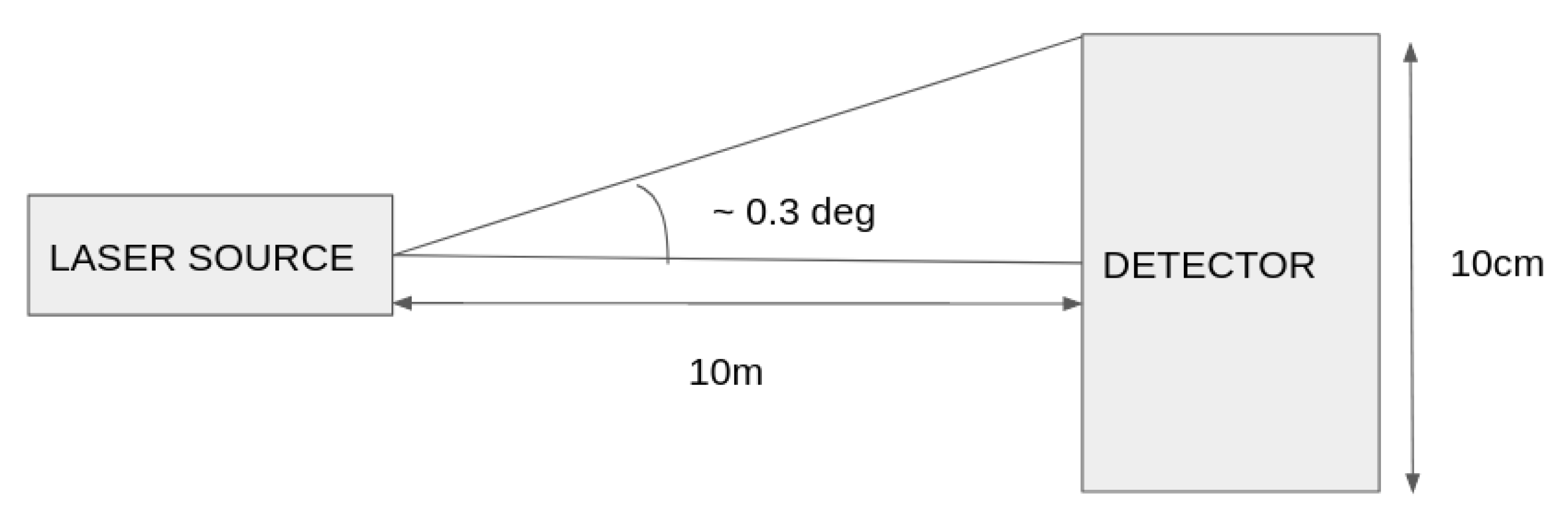
Figure 1 shows the basic concept of a proposed distributed optical system along with assumptions on the position accuracy to ensure a functional system. Assuming a fixed detector in the inertial frame, a deterministic error source model and zero laser beam divergence, the size of the detector area determines the required relative pointing performance of the laser source. A larger detecting area can tolerate higher pointing errors but encounters practical payload size and weight limitations. As an example, as shown in
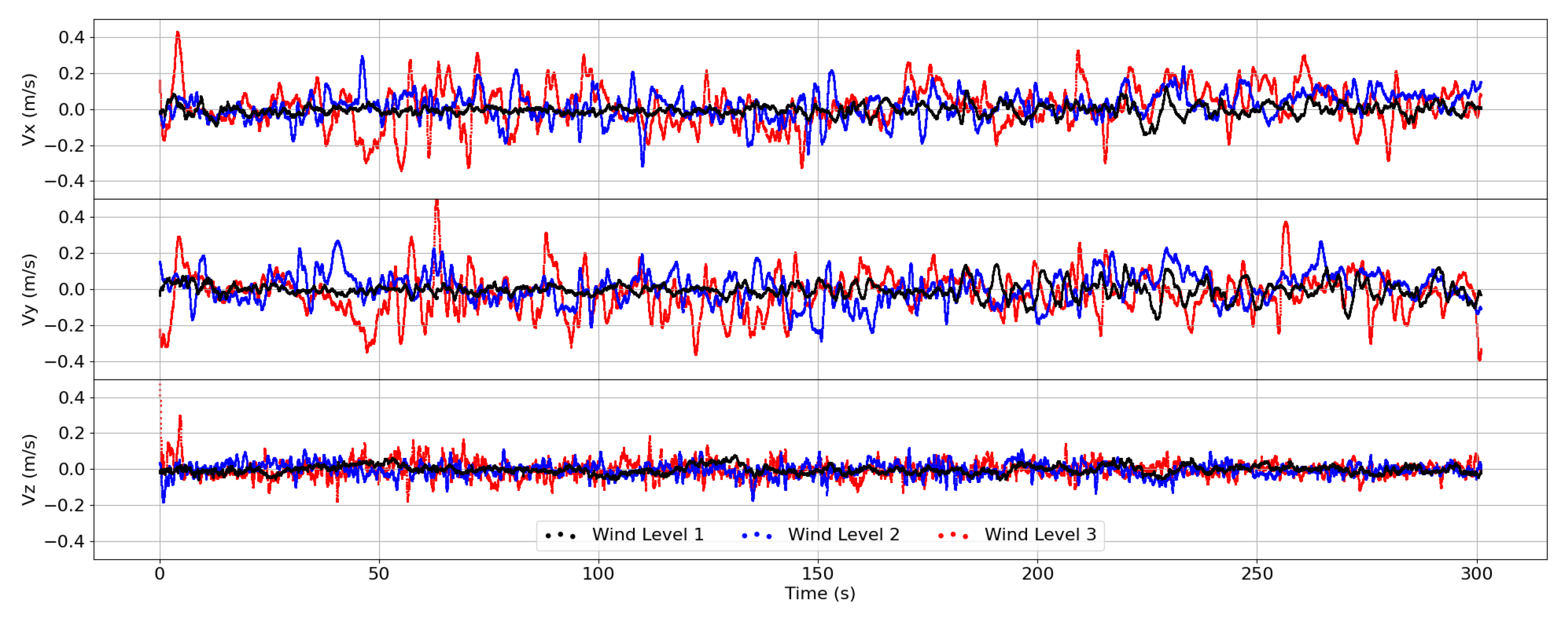
Figure 1, a detector diameter of 10 cm (realistic size for a heavy UAV such as DJI Matrice M600) and a path length of 10 m between the two UAVs can tolerate pointing errors up to 0.3°. The UAVs must keep a minimum distance of 10 m along the measurement axis. It has to be noted that these requirements are based on the assumption that there is no relative movement between the laser source and the detector. In practice, however, the relative movement between the laser source and the detector is unavoidable. Moreover, both UAVs need to be controlled to avoid relative movements even under adverse turbulent wind conditions of the lower atmosphere where such measurements have to be carried out, which are described for typical situations in
Section 3.
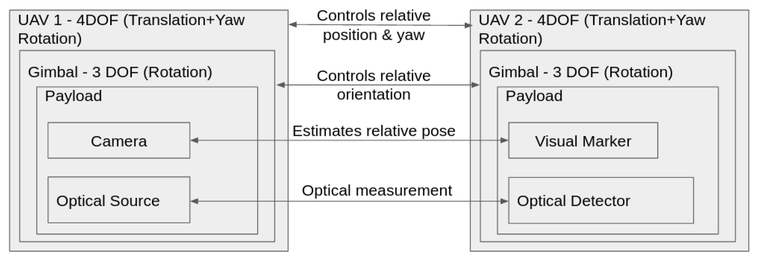
The introduced concept, however, places strict requirements on the control performance of the UAVs which need to keep the sensors oriented close relative to one another. It is known that a multi-copter UAV is underactuated and hence not all six degrees of freedom (DOFs) are independently controlled. With effective four DOFs, the multicopter can control the altitude, yaw, pitch, and roll independently, but the movement in the horizontal plane is always accompanied by the roll or the pitch motion. In order to fulfill the position and pointing requirements, a gimbal stabilization system is proposed for the overall concept in
Figure 2. Two participating UAVs are multi-copters and equipped with a three-axis gimbal stabilization system. The UAVs maintain the relative position (horizontal and vertical plane) between each other as fixed as possible. Due to the external disturbances and inherent sensor and controller inaccuracies, the UAVs would tilt along the pitch and roll axes. The three-axis gimbal balances these angular disturbances to keep the orientation of the payload in a fixed state. When two gimbal systems are used to keep the respective orientation between the two payloads integrated on these gimbals, the relative orientation error between the two payloads can be determined from a camera and visual markers system. The relative orientation controller would minimize this error using a closed-loop feedback.
To evaluate the feasibility of the concept, several topics need to be addressed: (I) the state knowledge accuracy of both UAVs characterizes the onboard estimation of attitude, rates, position, velocity, and time. (II) The performance of the gimbal stabilization system places requirements on the control performance of the UAV. (III) The transient and steady state pose control performance of both UAVs defines the operational mode of the proposed concept.
This work focuses on the last two points. In particular, experiments are conducted to evaluate the performance of the gimbal stabilization system. Flight tests are performed with different UAVs to characterize the operational environment (in particular the turbulent atmospheric flow) and the actual accuracy of the so far used commercial off-the-shelf position estimation sensors and flight controllers.
To circumvent the lack of accurate position estimation in outdoor flight tests, the proposed controller is evaluated in a controlled laboratory environment called ELISSA, an air-bearing table equipped with a state-of-the-art motion capture system. The obtained outdoor flight data is used as input to develop realistic models to simulate disturbances (e.g., turbulence effects on UAV dynamics) in ELISSA. The approach used is based on the determination of control inputs required to generate aircraft angular and translational rates in controlled laboratory conditions that are consistent with rates observed when flying in atmospheric turbulence.
2.2. Flying Platforms
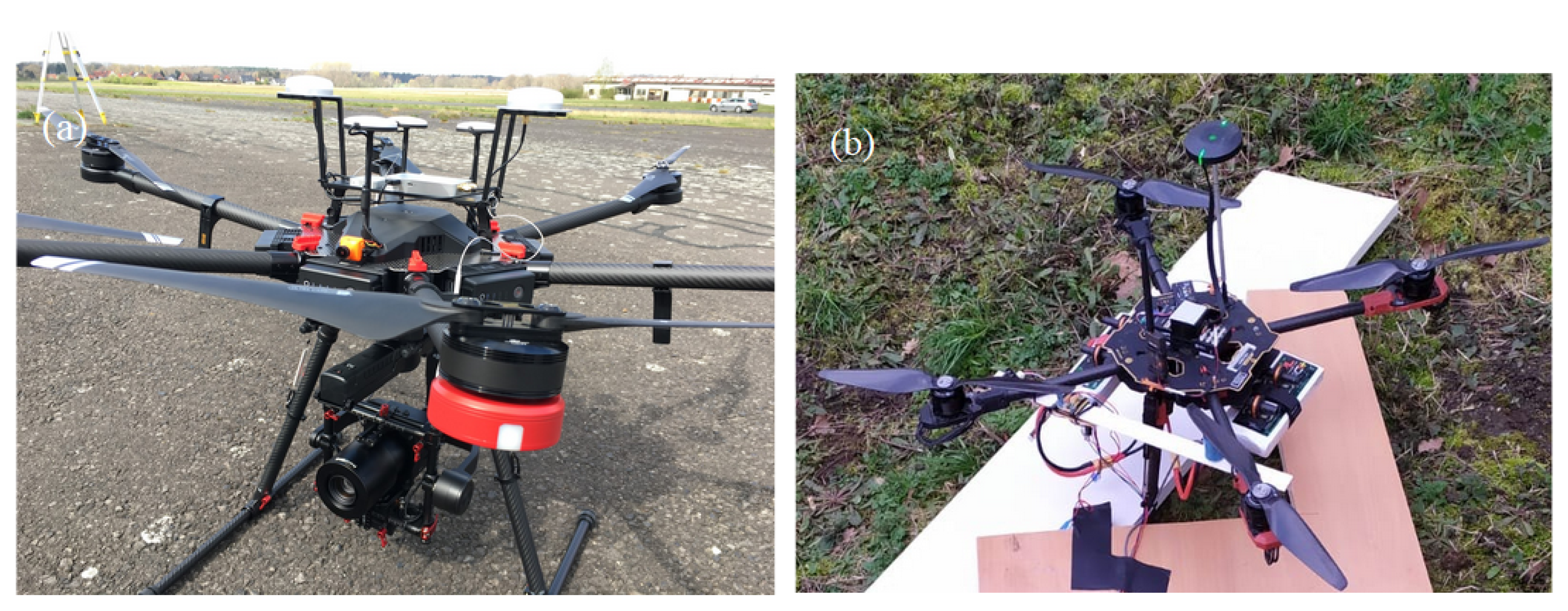
Two different multicopters, a DJI Matrice M600 Pro and a Tarot X4, as shown in
Figure 3, are used for this study. The detailed specifications of both multicopters are provided in
Table 1.
2.2.1. DJI Matrice M600 Pro
DJI Matrice M600 Pro is a commercial grade heavy lift UAV capable of carrying payloads of up to 5 kg with a flight time of more than 20 min. The UAV uses a triple redundant global navigation satellite system (GNSS) and IMU system for state estimation in the base configuration. It is possible to have an additional dual real time kinematics (D-RTK) position and attitude estimation system for centimeter-level accuracy and accurate attitude estimation even under high magnetic interference situations. The system consists of two units, one mounted on the UAV (called air unit) and one fixed on the ground (called base unit) with known surveyed position. The air unit has two dual band antennas at a fixed separation of 31 cm for precise heading estimation. The dual frequency capability takes advantage of the multi frequency signals from the newer GNSS satellites for faster and reliable position fix, even with less number of GNSS satellites in view. The base unit with known calibrated position can calculate the errors in the GNSS signals. Based on base station measurements and the carrier phase measurements of the used GNSS signals, nearby GNSS receivers can calculate their positions very accurately. This concept is called real time kinematics which is a type of differential GNSS. As per the manufacturer description, the use of RTK allows a position accuracy of up to 2 cm. The UAV can be controlled from standard manufacturer applications. Custom control softwares can be developed either using a mobile software development kit (MSDK) available for Android OS or iOS, or onboard SDK with a companion computer onboard the UAV directly connected to the flight controller. The flight controller hardware used is the DJI A3 which has a DJI proprietary firmware installed which is not open for user customization. An onboard computer (Nvidia Jetson TX2) is used within the robot operating system (ROS) to log all the data in a rosbag file, which also contains the timestamp when the data is acquired. Only IMU data (linear acceleration and angular rates) is available as raw data. The position data, GNSS or RTK (at 10 Hz) is always fused with the IMU data (at 400 Hz) for a fused solution (published at 100 Hz). Although the flight controller also records all the data, only a few data fields are openly accessible.
2.2.2. Tarot X4
Tarot X4 is a lightweight quadcopter with a single GNSS for position estimation and a ProfiCNC Pixhawk flight controller which has triple redundant IMU and a barometer for height estimation. As an autopilot, the PX4 open source firmware is installed. The firmware allows various settings to be changed such as the type of the control algorithm. It is also possible to easily extend this firmware for future scenarios. The Tarot UAV’s data is logged on a SD card onboard the flight controller which contains one log for each power cycle of the UAV. The log is in a PX4 format, but since the format is openly available, the data was initially processed using the open source tool pyulog and flight review [
23]. Additionally, this UAV was fitted with a RTK system (SparkFun uBlox F9P RTK) for better accuracy of position estimation.
2.3. The ELISSA Lab
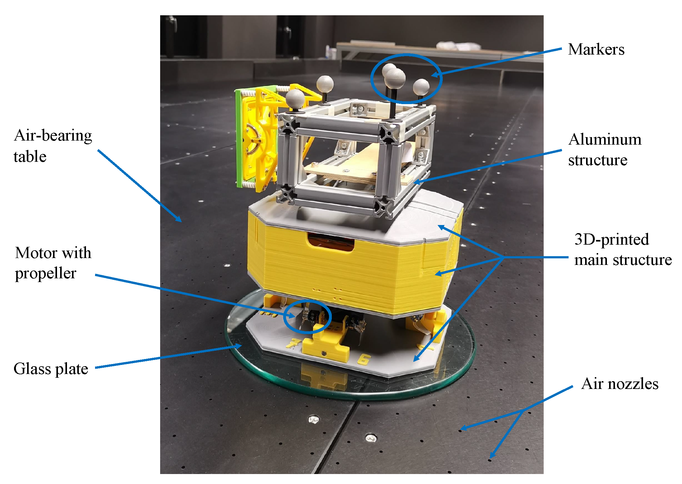
The Experimental Lab for Proximity Operations and Space Awareness (ELISSA) is a facility at the Institute of Space Systems of TU Braunschweig. The goal of ELISSA is to enable the emulation of weightlessness and contact dynamics of spacecraft in orbit. ELISSA (as shown in
Figure 4) is mainly composed of four parts: the aeromechanical subsystem, the motion capture subsystem, the mission control subsystem, and the free flyers (FF) subsystem. The aeromechanical subsystem transports air mass and generates the air cushion on the air-bearing table for the FFs. Unlike most air-bearing tables in research facilities, where satellite mockups need to incorporate tanks of high-pressure gas to generate air cushions, the air-bearing table in ELISSA environment can generate air cushions by itself with high-pressure airflow based on the SmartNozzle
technology of the company CoreFlow [
24] and thus, enables a long duration of experiment. A maximum weight of 30 kg can be floated per 0.05 m
. The OptiTrack [
25] motion capture subsystem with six Prime 17W cameras measures the position and the attitude of mockups. It can achieve a state knowledge accuracy of 0.25° in attitude and 1 mm in position. The mission control subsystem, which is based on ROS, allows the operation of the whole infrastructure. It generates command signals for the whole environment to conduct the experiment. At present, satellite mockups can have three-DOF motions including two DOFs for the translation and one for the rotation.
The 3D-printed main structure of the mockup (as shown in
Figure 5) has a dimension of 22 cm × 22 cm × 26 cm and is used to mount 8 motors with propellers, various printed circuit boards (PCBs) and a LiPo battery. On the top of the main structure, an aluminum structure is fixed for installing payloads and markers for the motion capture system. The total weight of the whole structure (the 3D-printed main structure and the aluminum structure) with the LiPo battery is 2.87 kg. A Raspberry Pi is used as the onboard computer to control the mockup. When placed on a glass plate with a diameter of around 30 cm, the mockup can float freely on the air-bearing table.
Based on sliding mode control (SMC) technique, a controller is developed to control the motion of the mockup. With the conventional method of modeling the dynamics of a rigid body (i.e., position vectors for the translation and attitude parameterization for the rotation), two controllers are needed, of which one is for the translation and the other for the rotation. For the SMC design of ELISSA, dual quaternion parameterization is implemented to describe the translation and rotation of the mockup simultaneously. The developed dual quaternion-based SMC [
26] can generate command forces and torques for the translation and the rotation, respectively, at the same time. Thus, based on dual quaternion parameterization, only one controller is needed instead of two, which makes the mission control subsystem more compact. The developed SMC controller is a pose (i.e., position and attitude) tracking controller which can be used to track a predefined pose trajectory.
Although ELISSA is designed to simulate the weightlessness and contact dynamics of spacecraft in orbit, it can also be used as a testbed to investigate the concept of distributed sensor platforms in the current project. The reasons are as follows.
First, since the payloads (namely the laser source and the detector) are expensive and easy to be damaged, it would be very risky to directly test the concept with the real payloads in flight. In this perspective, ELISSA offers a safe test environment for the preliminary validation of the concept. To be specific, both the laser source and the detector can be floated on the air-bearing table in ELISSA to simulate the in-plane relative motion during the flight. Thus, insights can be obtained for the concept development without risking expensive payloads.
Next, the motion capture system in ELISSA can achieve high accuracy in measurements (0.25° in attitude and 1 mm in position). As there is a high requirement on the control performance of the multicopters and the gimbal system, the ELISSA environment can be used to accurately assess the achievable performance of the proposed concept.
Last, since SMC is chosen as the control technique for the relative position control in the proposed concept of distributed sensor platforms, ELISSA can provide the HIL environment to evaluate the performance of SMC. The experience and lessons learned with SMC using ELISSA can be helpful for the implementation of SMC in the proposed UAVs formation flying.
2.4. Wind Disturbance Model Extraction
There is a large body of literature dealing with extraction of wind disturbance models from flight data. In [
27,
28,
29], a dynamic model of UAV is used to extract the wind disturbance from onboard sensor data (e.g., IMU accelerations, angular rates, and attitude). To create a dynamic model, complicated aerodynamic tests were carried out in a wind tunnel for obtaining the necessary aerodynamic, inertial, and thrust relationships for the UAV. This was, however, not practical for our project. In order to evaluate the performance of SMC under wind disturbances in ELISSA, a model of wind disturbance suitable for real-time HIL implementation is needed.
Inspired by the control equivalent turbulence input (CETI) method in [
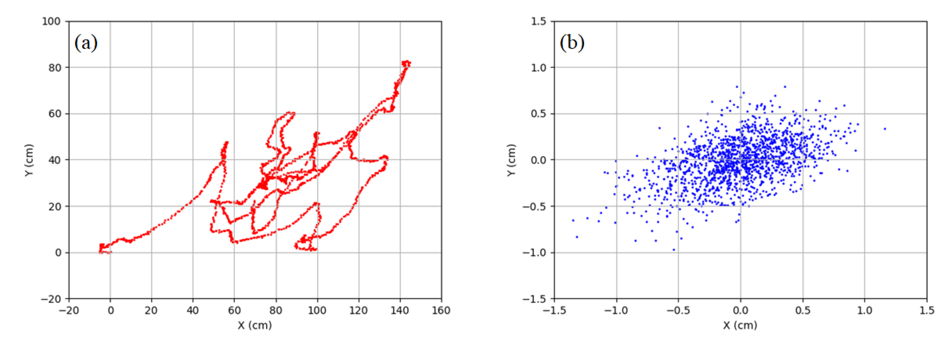
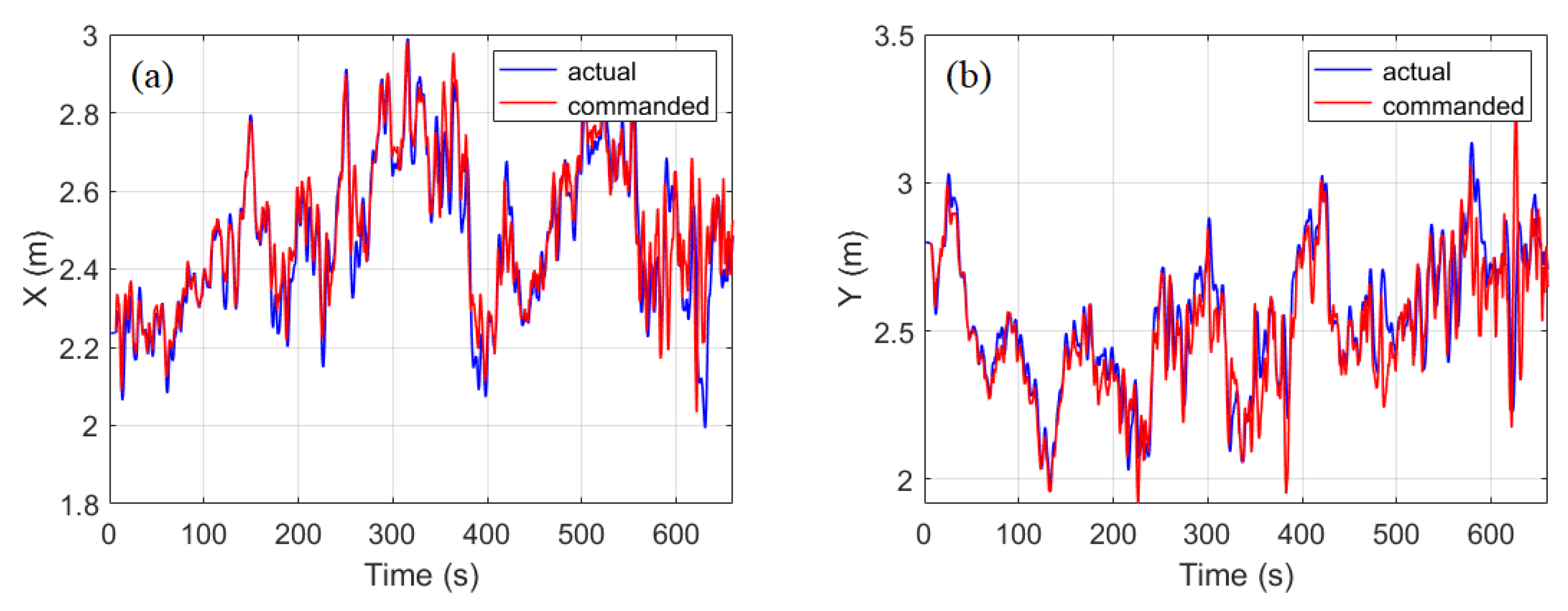
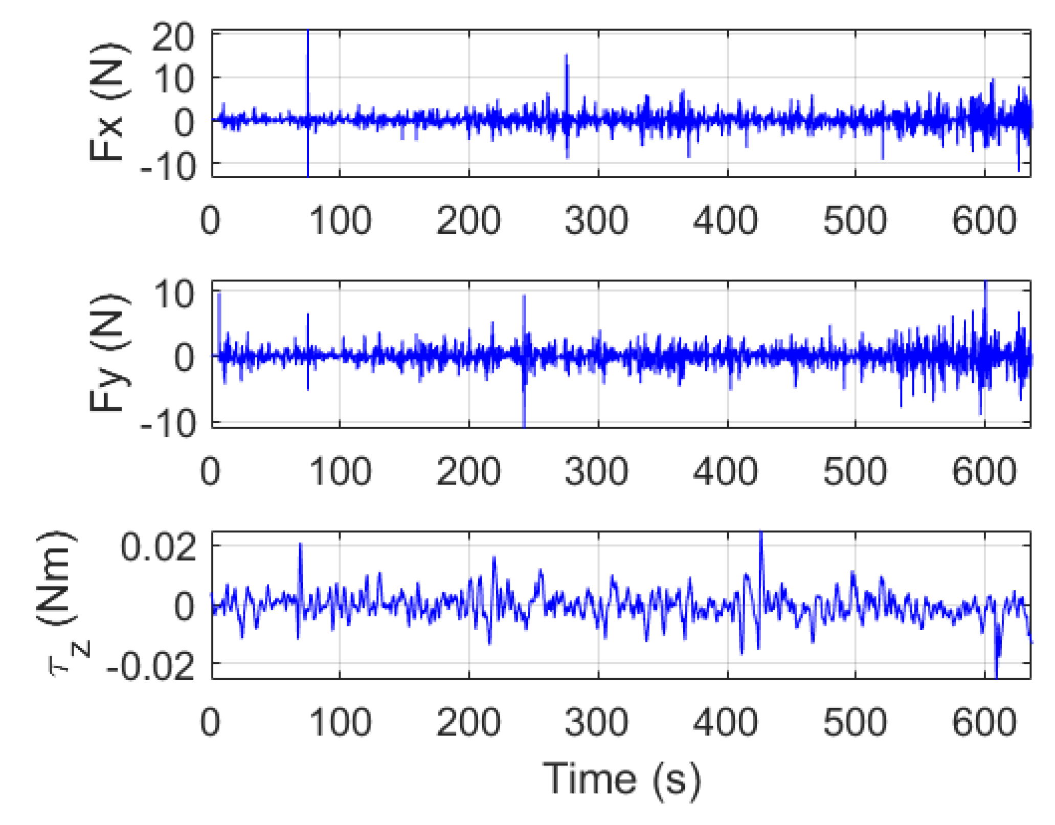
30], a relatively easy way to extract wind disturbance is proposed to preliminarily study the effect of wind disturbance using ELISSA. The basic idea is to let the mockup simulate the measured horizontal movement of UAVs in gusty winds and then record the time history of control commands of the mockup when it tracks the reference movement. The recorded control sequence can be regarded as the disturbance the mockup will experience in the wind. The extracted pseudo wind disturbance model is added to the guidance, navigation, and control (GNC) system of ELISSA as external disturbances. The translational reference trajectory is based on measured motion of UAVs in the XY plane. The yaw angle is assumed to be zero in the reference motion. As only position information in the measured data is used, a numerical differentiation method is used to calculate the reference velocity and acceleration. In order to reduce the influence of the measurement noise on the differentiation, the measured flight data is smoothed. The smoothed position information, the calculated velocity, and acceleration are fed into the dual quaternion-based SMC as the translational reference trajectory.
However, when using the above mentioned method to extract wind disturbances for experiments on the air-bearing table, the following issues should be noted: First, the reference trajectory (i.e., the measured flight trajectory of UAVs in XY plane in gusty winds) is actually a result of the regulation control of the UAV and wind disturbances. As a result, the extracted disturbance forces are mixed with control efforts of the UAV’s controller. Second, as the reference trajectory needs to be tracked in the methodology, the control accuracy of tracking the reference trajectory based on SMC also affects the obtained results. Third, when different mockups are used, it needs to run the trajectory tracking experiment again using the same reference trajectory in order to extract the wind disturbance forces.
Although there are drawbacks in the proposed method to obtain the wind disturbance model, in the future, it can still be used for the evaluation of SMC and the gimbal system for the proposed concept.
4. Conclusions
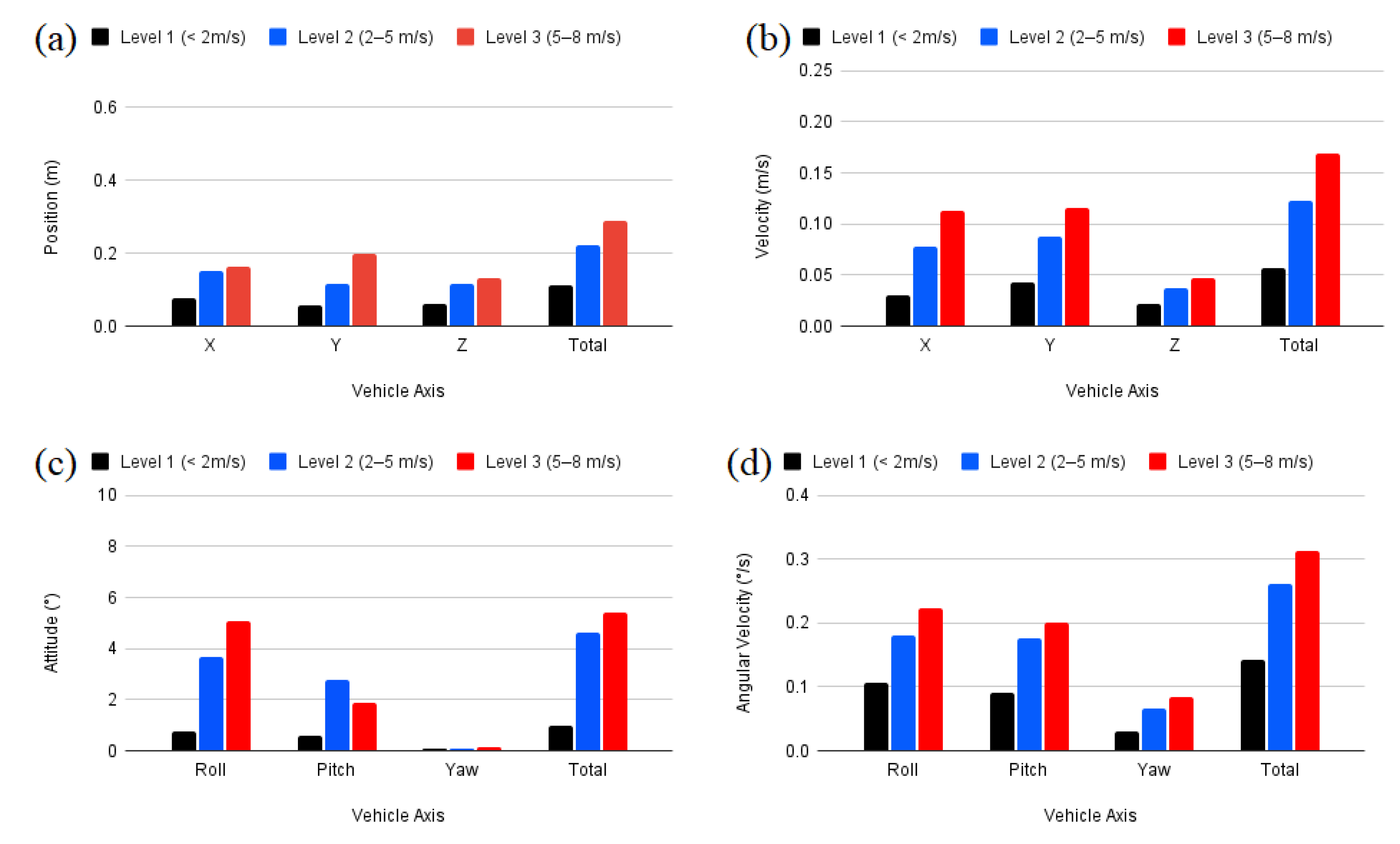
This paper proposes to use multicopters in tandem flying as a distributed sensor platform for optical atmospheric measurement. Gimbal stabilization systems are introduced to achieve the high pointing performance of the payloads. Preliminary requirements on the control accuracy of the relative position and attitude of the components are estimated. Flight experiments using off-the-shelf UAVs under different wind conditions were conducted to evaluate the accuracy of sensor measurements and the positioning control. Compared with GNSS alone, RTK based position control provides more precise position estimation and is recommended for the tandem flight application. In terms of the sensors, the flight controller, and payload capacity, DJI M600 UAV has better performance than Tarot UAV for the proposed concept of distributed optical measurements using tandem flying. Specifically in wind speeds of more than 5 m/s, the much smaller Tarot UAV performs much worse. An increase in weight increases the wind tolerance. It is therefore recommended to use a higher weight class (>10 kg MTOW) UAV for applications under extreme wind conditions.
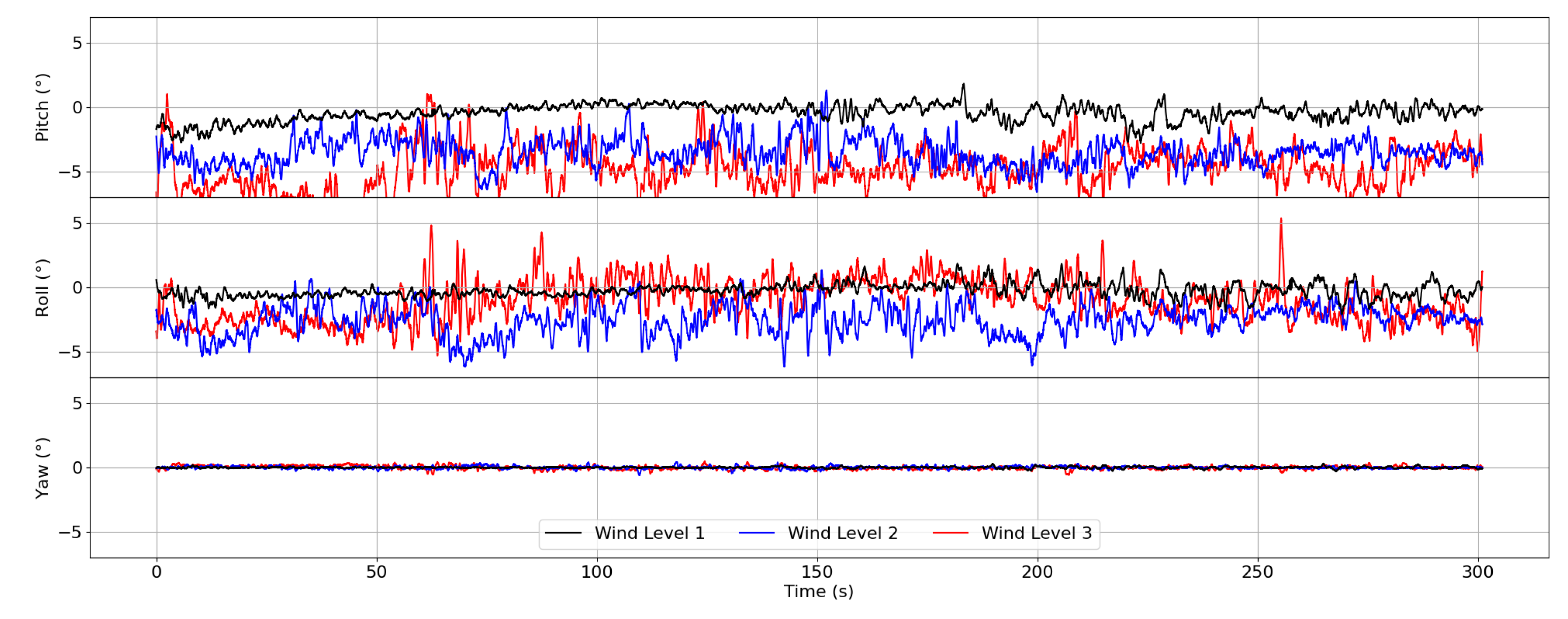
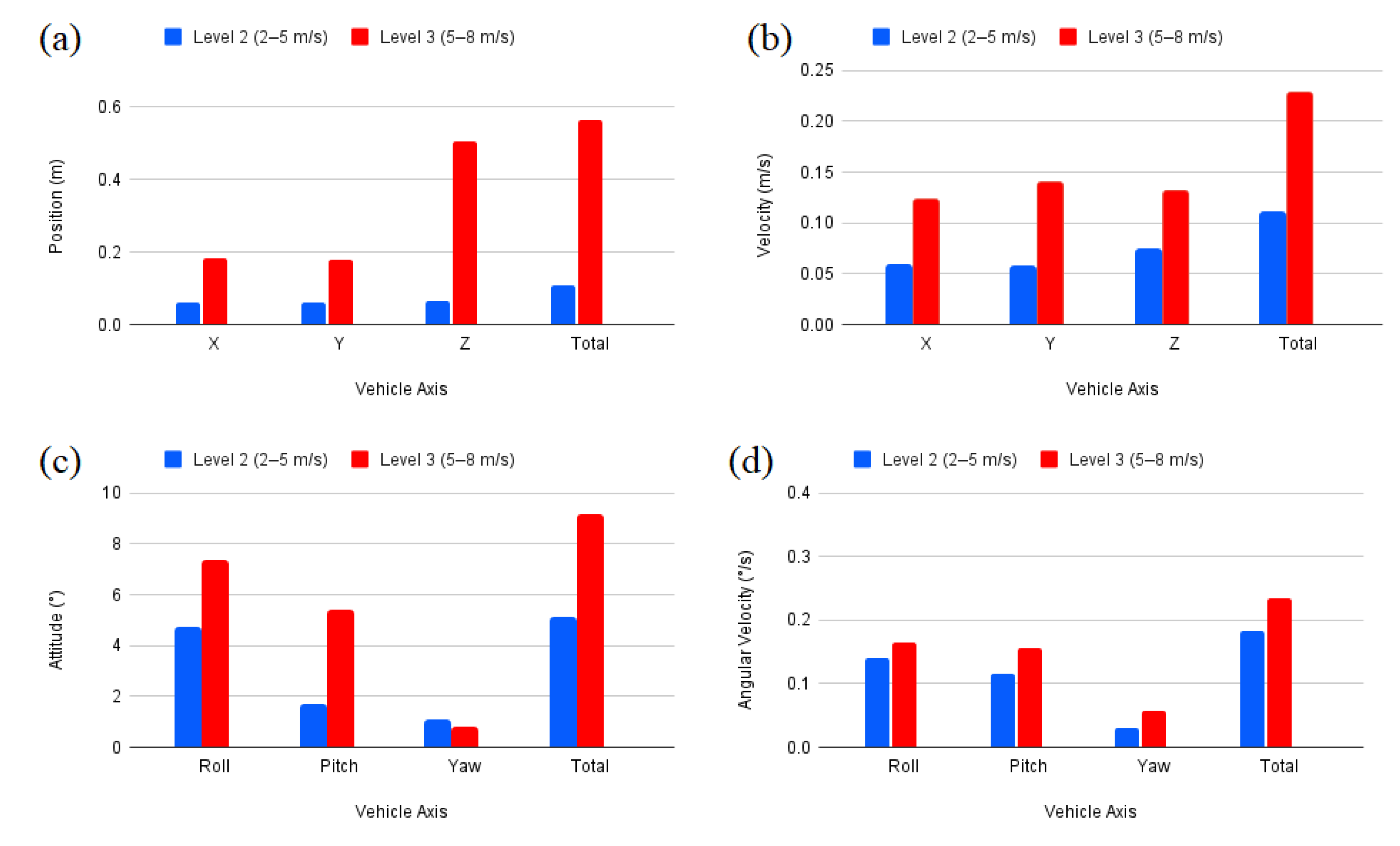
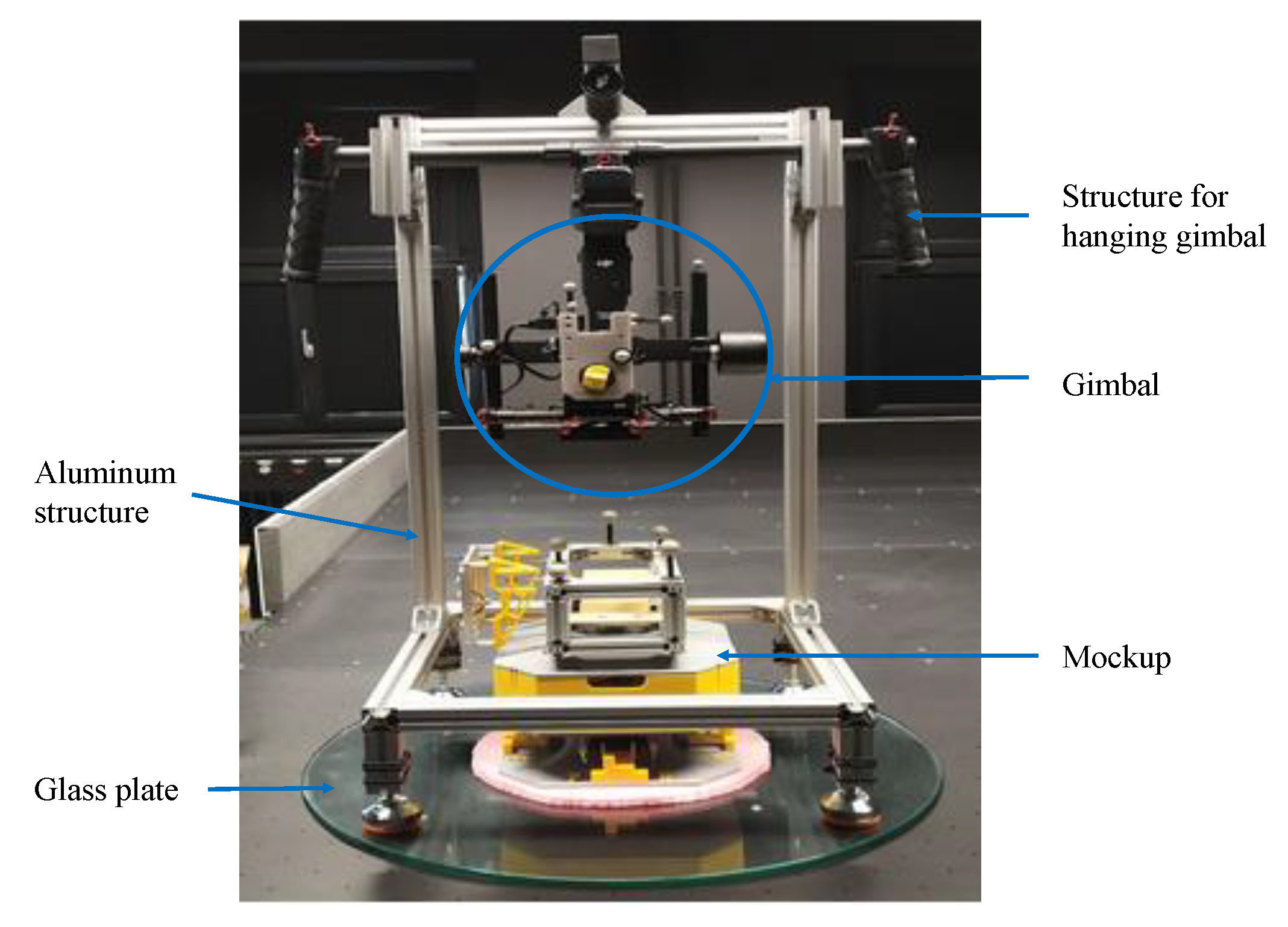
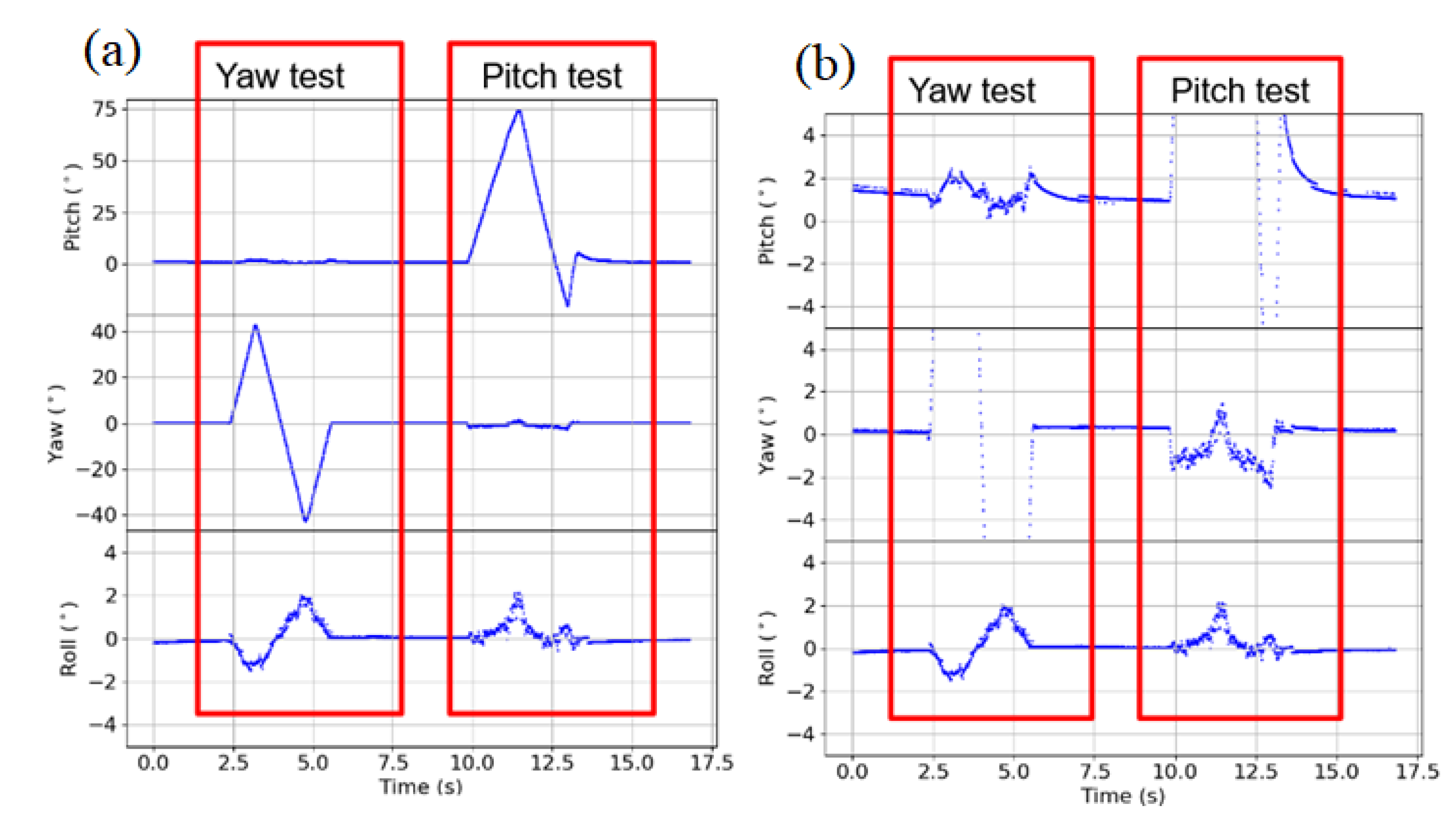
As there was no defined case study to prove the proposed concept and the relative position controller was not implemented for the flight, flight tests were conducted only with individual UAVs to explore the achievable performance of a single UAV in the concept. This can help to avoid impractical requirements defined for the system. Although the UAV (DJI M600) drifts up to a maximum of 50 cm from the set point under extreme wind gusts, this drift still remains small with an order of 10 cm over short time span. This implies that it is possible to have precise position control over small time scales. The same is applicable to the UAV attitudes which remain below 7° even with wind gusts up to 8 m/s. The gimbal system was shown to keep a steady attitude around the set point even under motion of the mockup. Only when the mockup makes drastic yaw changes of up to 30°, the roll and pitch axes of the gimbal move up to a maximum of 1°. During flight, however, the yaw axis of the UAV was found to be relatively stable around the set point, varying less than 1°. It can be concluded that, even in combination with the relatively good position control of the RTK based DJI M600, the accuracy requirements mentioned in
Figure 1 cannot be met with the existing system. Since the yaw is relatively fixed, the two UAVs should be positioned in such a way that they are facing towards each other. Then the plane perpendicular to the yaw axis of each UAV would remain relatively fixed with respect to each other. Any relative motion along the yaw axis is therefore not as bad for the sensor pointing as the motion along roll and pitch axes. This result also has implications on the relative position controller design since relative position accuracy requirements for Y (lateral motion) and Z (vertical motion) are more stringent compared to X (forward motion). Moreover, the UAV vertical movement shows much less drift even under wind disturbances. One limitation with the current gimbal system, however, is the inaccessible control system. Access to the control system would allow to control the relative attitude of the two UAVs within the proposed limits of within 0.3° when combined with RTK based position estimation and a dual quaternion-based control of both UAVs.
The ELISSA lab was used to evaluate the performance of dual quaternion-based SMC. In experiments, a control accuracy of 2–5 cm was achieved for the position control. It is promising to use SMC for the relative position control in the proposed formation flying. A wind disturbance model was extracted based on tracking the measured flight trajectory of UAVs. In spite of the simplicity of the disturbance extraction method, it allows to preliminarily evaluate the performance of the SMC controller under wind disturbances in ELISSA.
In future works, a complete dual mockup setup with gimbal stabilized optical measurement system would be created and experimented first on ELISSA. Upon successful evaluation on the ELISSA, two UAVs would be prepared along with an implementation of the dual quaternion-based SMC for real UAV flights. This setup would be used to validate the proposed formation flying-based concept of optical measurement in outdoor flights.
