Abstract
Cloud and precipitation radar mounted on a polar orbiting satellite opens up a new opportunity for global wind observation to improve numerical weather forecasting and prevent weather disasters. However, no related works have been done to retrieve the wind field for spaceborne cloud and precipitation radar. This is mainly because the high-speed motion of satellites makes wind field retrieval complex. This paper developed the first spaceborne version of the velocity–azimuth display (VAD) technique for wind field retrieval, which was originally created for ground-based radar. After derivation of VAD for spaceborne radar, we found that the product of the azimuth of the radar beam and its first harmonic was introduced into the Fourier series of radar radial velocity due to the motion of the satellites. The wind retrieval equations were developed by considering the effects of satellite motion and conical scanning strategy of radar. Numerical simulations of the spaceborne radar showed that the proposed VAD method provided a mean vertical profile of the horizontal wind with high vertical resolution over a large observation swath. Validations on airborne radar data with the same conical scan strategy as the spaceborne radar were carried out to capture the average wind structure in one hurricane event. The real data results demonstrated that the wind-retrieved results by the proposed method were consistent with the ground truth data, indicating the potential use of our proposal for spaceborne radar.
1. Introduction
Wind field is the main physical parameter describing the spatial distribution and temporal evolution of atmospheric motion [1], which plays a unique role in the research of numerical weather forecast, climate diagnosis, prediction, etc. [2,3]. As one of the most key meteorological disasters, windstorms cause serious casualties and economic losses every year [4,5,6]. Therefore, the measurement of global wind field is of great significance for in-depth understanding of the physical mechanism of the development and evolution of the weather system, improving the weather forecast accuracy and disaster prevention and mitigation. However, due to the limitation of existing observation methods, the global wind field in cloud and precipitation has not yet been observed in the current Global Observing System (GOS) [7,8].
Promisingly, radar mounted on a polar orbiting satellite opens up a new opportunity for global wind field retrieval with its observing characteristics of high-speed flight. In order to investigate the feasibility of such radar systems, Lemaître and Viltard [9] used a simulator to evaluate the sensitivity of the retrieved wind fields to the instrumental parameters. The authors of [10] described two different antenna scanning methods of spaceborne Doppler radar at 94 GHz. Recently, Illingworth et al. [11] presented a new concept of spaceborne Doppler radar using the conically scanning antenna to focus on using line-of-sight winds for data assimilation. In summary, the published studies show a promising future for the global wind field retrieval, however, they all focused on the design of radar systems, including the scanning strategies and platform parameters, not the wind retrieval method.
The authors of [12] proposed an optimized scanning strategy for the spaceborne radar to obtain three noncollinear observations that were successfully used for the three-dimensional (3D) wind field retrieval of a simulated tropical cyclone. However, this strategy seems a bit too complicated for the satellite platform due to its computational consumption. Velocity–azimuth display (VAD) technique is a classic wind field retrieval method with advantages of requiring only a few calculations and having good real-time performance [13,14]; it has been used widely for ground-based Doppler weather radar (NEXRAD WSR-88D [15,16,17], CINRAD WSR-98D [18]) and plays a significant role in data assimilation and operational forecast [19]. Due to the similarities of the conical scanning method to that of ground-based radar, it is of great significance to study the application of the VAD technique in the wind field retrieval of spaceborne radar.
The VAD method was first proposed by Lhermitte and Atlas [20] in 1961. Assuming that the wind field in the precipitation area is horizontal and uniform, it can retrieve the average horizontal wind speed at different altitudes and the average vertical wind speed. Under the assumption that the horizontal wind field is linearly distributed, Browning and Wexler [21] performed harmonic analysis on the VAD radial velocity, and then the kinematic properties of the wind field were educed. On this basis, people have improved the VAD method and proposed the extended VAD [22] method. Under the assumption of local uniform wind, the least square estimation is introduced, so that the VAD method can be used to extract the horizontal divergence and vertical wind field [23]. In recent years, the VAD method has been applied to a conically scanning airborne radar, which could obtain average horizontal wind information with higher vertical resolution [24]. Studies show that the method can successfully capture the average wind field of a hurricane [25,26,27]. However, it ignores the influence of the azimuth angle and the first-order harmonic product term introduced by the conical scanning under the aircraft motion when calculating the harmonic coefficient by azimuth integration [24].
Due to its large observed swath, the satellite platform has unique advantages for large-scale uniform linear wind field observation [28]. However, there is no research on the VAD method in the wind field retrieval of spaceborne Doppler radar. The application of the VAD method in spaceborne Doppler cloud and rain radar mainly has the following difficulties:
- (1)
- The VAD method requires the radar to perform a conical scan. Compared with the stationary ground-based weather radar, the spaceborne radar has a higher flight speed, and the beam footprint of the antenna conical scanning is spiral rather than circular. This will change the first step of the Taylor series expansion of the wind field, thus affecting the determination of VAD coefficients at all levels.
- (2)
- Compared with airborne radar, the movement speed of spaceborne radar is much higher. Since the height of the satellite platform is much larger than that of the airborne platform, for the same downward viewing angle, the swath width is much larger, while it is difficult for the horizontal resolution to reach the level of the airborne radar. This poses a challenge to the application of the VAD method in the wind field retrieval of spaceborne Doppler cloud and rain radar.
To address the challenges mentioned above, this paper developed for the first time a spaceborne version of the velocity–azimuth display (SVAD) technique for wind field retrieval. The remaining parts of this paper are organized as follows. Section 2 presents the proposal. The observation geometry and coordinate system of spaceborne radar is established, and the spaceborne version of the VAD is developed in detail. In Section 3, numerical simulations on the spaceborne radar are conducted. Section 4 demonstrates validation on the airborne radar with the same scanning strategy as that of the spaceborne radar. Discussions and conclusions are drawn in Section 5 and Section 6, respectively.
2. Methodology
2.1. Observation Geometry and Coordinate System
The spaceborne radar is designed as dual-frequency (Ku- and Ka-bands), each band has two beams with incident angles ranging from 23° to 40°. The azimuth rotation rate of the antenna is approximately 60 rpm, so a complete rotation takes only one second. A more detailed description of the system parameters can be found in [12]. In this paper, only one beam was chosen to investigate the application of the VAD technique.
Geometries of observation and motion for the spaceborne radar are given in Figure 1a. For convenient calculation, the angle between the projection of the beam on the horizontal plane and the positive -axis (along the flight track and pointing eastward) is defined as the azimuth in this paper, the -axis points 90° to the left of the -axis, and the -axis points to the local zenith, obeying the right-hand rule. The radar beam performs a counterclockwise conical scan with a fixed incident angle, sweeping out spiral ground trajectories due to the movement of the satellite, as shown in Figure 1b. This method can obtain the observation data of the approximate conical surface. As the satellite moves, the cones are superimposed on the front and back, and then the 3D observation data can be generated.
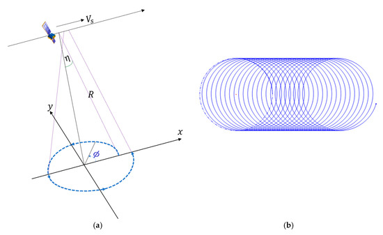
Figure 1.
Illustration of the observation geometry. (a) Scanning geometry; (b) Surface coverage of beam trajectory.
Assuming is the satellite orbital height and is the incident angle, the swath width can be approximately 2. For a typical satellite speed of 7.6 km/s and altitude of 500 km, the swath width will reach 840 km with an incident angle of 40°, which has obvious advantages for the observation of large-scale weather systems.
2.2. Derivation of Spaceborne Version of VAD Technique
After a short description of the spaceborne radar, we now deduce the VAD method. As shown in Figure 1, is the satellite speed. Following the convention that negative Doppler velocities are towards the radar and positive ones are away, the radial Doppler velocity of the spaceborne radar along the VAD circle can be expressed in terms of the 3D Cartesian velocities, , , and as:
The wind vector at the center (, , of the spiral beam footprint (directly below the satellite) is marked as , , . Assuming that the horizontal wind field is linear and the vertical component of the wind field at the same height is constant, as illustrated in [21], by using Taylor series expansion, the wind field component at any point (, , at the same height can be expressed as
It is worth mentioning that the assumed linear horizontal wind distribution neglects all other types of horizontal variations (including those generated by storms) in the true horizontal wind over a large swath width of the spaceborne radar. Due to the high-speed movement of the satellite, the center of the VAD changes along the flight direction, so the center point of the linear expansion of and in Equation (2) is not fixed, and each center is separated by 7.6 km. Assuming that the antenna rotation period is and the slant distance from the radar to any observation target at the same height is , as shown in Figure 1, we have
Substituting Equation (2) and Equation (3) into Equation (1) we can get
The above equation can be further abbreviated as
The coefficients are
where is the divergence of the horizontal wind. From the above derivation, one more item is introduced to the radar radial velocity due to the movement of the satellite compared with a ground-based stationary platform, which is the product of azimuth angle and its first harmonic.
By performing a complete conical scan, the spaceborne radar can obtain the radial velocity within [0, 2π]. Therefore, the coefficients in Equation (6) can be determined by integrating the product of the harmonics of the radial velocity and the azimuth angle in one scan period. For all the harmonics, we have
It can be further deduced that
The matrix notation of the above equation is expressed as
where
Solving the above equation, we can get
where
According to the above derivation process of the SVAD wind field retrieval method, we can see that the VAD formulations are modified by the satellite moving speed, but the satellite moving speed does not affect the estimations of , , . The performance of the method is analyzed in the following section.
3. Numerical Simulations
In this section, we illustrate the utility of the SVAD wind retrieval algorithm for spaceborne radar using simulated wind field, including uniform and linear wind field. The simulation settings are given in Table 1.

Table 1.
Parameters for simulation.
First, the retrieval performance of the SVAD method for uniform wind field is examined, that is, let the gradient of each direction in Equation (2) be zero. According to the observation geometric relationship established in Section 2, the horizontal wind field at the ground coverage position of the radar scanning beam footprint can be obtained, as shown in Figure 2.
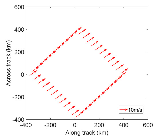
Figure 2.
Uniform wind field at the location covered by the radar beam footprint.
Figure 3 shows the change of radar radial velocity with azimuth angle. It can be seen that for the conical scanning spaceborne radar, the radial velocity of a uniform wind field is no longer a regular trigonometric function. This is caused by the high-speed movement of the satellite platform where the radar is mounted.
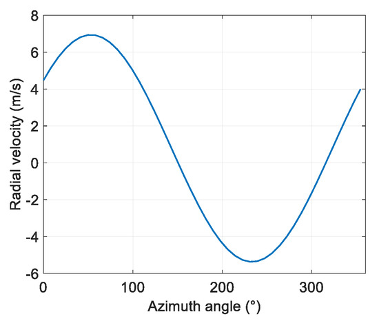
Figure 3.
The variation of radial velocity of spaceborne radar with azimuth in uniform wind field.
Next, we evaluated the performance of the method under different signal-to-noise ratios (SNRs). Figure 4 shows the variation curve of the radar radial velocity with the azimuth angle when the SNR is 5 dB, 10 dB, and 20 dB, respectively. It can be seen that the radar radial velocity curve becomes rough at low SNRs, which will affect the retrieval accuracy of the average wind field.

Figure 4.
Variation of radial velocity with azimuth angle in uniform wind field under different signal-to-noise rations (SNRs). (a) SNR = 5 dB; (b) SNR = 10 dB; (c) SNR = 20 dB.
According to Section 2, the average wind field components at different SNRs are calculated as shown in Table 2. It can be seen from the table that the retrieved horizontal wind field component is close to the real value, while there is a larger error in the retrieved vertical component. That is because the calculation of the vertical wind field component is not only related to the flight speed of the satellite platform but also to the gradient of the horizontal wind field in different directions, as shown in Equation (11), so a large accumulated transmission is generated.

Table 2.
Performance analysis of uniform wind field retrieval.
Then, the performance of the linear wind field retrieval is considered. The setting of wind vector at the center is consistent with Table 1. The gradients of each direction of the horizontal wind field are set as m/s/km, m/s/km, m/s/km, and m/s/km. Figure 5 shows the linear wind field distribution at the position of the beam footprint of the spaceborne radar conical scan under this parameter configuration. It can be seen that due to the positive directional gradient that we set, the wind field increases in the direction where the and axis coordinates increase.
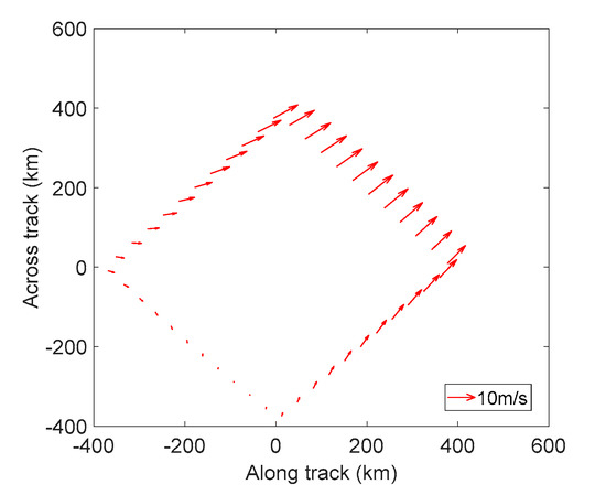
Figure 5.
Linear wind field distribution at the location of the spaceborne radar beam footprint.
Figure 6 shows the variation of radar radial velocity of linear wind field with azimuth angle under different SNRs. The average wind field information calculated by the proposed SVAD is shown in Table 3. As the SNR increases, the retrieved horizontal wind field component is closer to the real value. However, similar to the uniform wind field, the vertical component has a larger retrieval error. In addition, there is a big error in the retrieved gradient values in each direction, even when the SNR is large.

Figure 6.
Variation of radial velocity with azimuth angle in linear wind field under different SNRs. (a) SNR = 5 dB; (b) SNR = 10 dB; (c) SNR = 20 dB.

Table 3.
Performance analysis of linear wind field retrieval.
Since the wind field retrieved by the VAD method is average wind information, the retrieval result of the linear wind field under the conical scanning strategy of the spaceborne motion platform deviates from the center wind speed. From the retrieval results of the uniform and linear wind fields simulated above, it can be seen that the VAD method can retrieve the horizontal average wind field under the spaceborne platform, nevertheless, there is a large error for the vertical component retrieval. In the case of high SNRs, the retrieved gradients in all directions have a certain degree of credibility.
4. Validation on Airborne Radar with the Same Scanning Strategy as Spaceborne Radar
In the previous section, the VAD retrieval method was successfully applied to simulated radar data. We now apply the VAD method to real data. However, with the current on-orbit or future instruments, such as Atmospheric Laser Doppler Instrument (ALADIN) [29] and EarthCARE [8], only cloud-free regions wind profiling and vertical wind components are accessible, respectively. Hence, there is no real spaceborne radar data that can be used to verify the method proposed in this article. Because of the same earth observation angle and moving observation platform, airborne radar is often used in the verification tests of spaceborne radar performance. Therefore, this paper uses the High-Altitude Imaging Wind and Rain Airborne Profiler (HIWRAP) Ka-band radar [30] developed by National Aeronautics and Space Administration’s (NASA’s) Goddard Space Flight Center to verify the wind field retrieval method.
4.1. HIWRAP and Data Description
NASA carried out a five-year observation mission called the Hurricane and Severe Storm Sentinel (HS3) [31] to study the formation and intensity changes of hurricanes in the Atlantic Basin. HIWRAP is one of the most important airborne loads in the HS3 mission and is mounted on the Global Hawk. Similar to the spaceborne radar studied in this paper, HIWRAP performs conical scanning observations on a high-speed moving platform. The typical flying altitude of HIWRAP is 18–20 km. From 2012 to 2014, HIWRAP conducted one-month observations in each hurricane season and obtained abundant radar-measured data [32].
Table 4 shows the parameters of HIWRAP Ka-band radar with an incident angle of 29.9° during HS3. Flying on an unmanned aerial vehicle with a height of 17.5 km and a speed of 170 m/s, the radar completes a conical scan every 3.8 s, tracing out an approximately circular ground track with a diameter of about 21 km, and advancing 643 m per revolution. The attitude, operating altitude, and flight speed of the airborne radar have been pre-calibrated.

Table 4.
Partial system parameters of the High-Altitude Imaging Wind and Rain Airborne Profiler (HIWRAP) Ka-band radar [33].
The real radar data collected during Hurricane Ingrid (No.AL102013) in 2013 was used to verify the SVAD. The whole track of hurricane Ingrid is shown in Figure 7. The generation of this hurricane was very complicated, and one of the factors was determined to be the tropical wave airflow that appeared on the coast of Africa on 28 August 2013. A heavy rainstorm occurred in the north of the tropical wave on September 2, which was eventually absorbed by tropical storm Gabrielle. The south part of the wave continued to propagate westward, and eventually an annular air flow was generated in the eastern North Pacific, forming a low pressure system on September 11. The system continued to develop until it entered the Gulf of Mexico on September 14, and the maximum wind speed reached approximately 40 m/s on September 15. Ingrid made landfall in the southern city of La Pesca, Mexico on September 16, and then gradually weakened and dissipated.
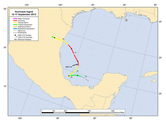
Figure 7.
Best track positions for Hurricane Ingrid, 12–17 September 2013 [33], the directions of longitude and latitude are north and west.
HIWRAP started at 18:34 UTC on 15 September 2013 and conducted a 40-minute observation experiment on hurricane Ingrid. At 18:00, the center of the hurricane was located at 22.7° N and 95.9° W, with a central pressure of 978.6 hPa and a maximum wind speed of 35 m/s. The starting longitude and latitude of the flight observation was 23° N and 93.118° W, and the end of the observation was 23.5° N and 96.6° W. The approximate path of the HIWRAP flight has been superimposed on the National Oceanic and Atmospheric Administration (NOAA) Multiplatform Satellite Surface Wind Analysis (MSWA) product (18:00 on 15 September) [34] in Figure 8. The purple dashed line in the figure is the flight observation path of the HIWRAP. It can be seen that during this flight, the radar made observations through part of the hurricane’s maximum wind circle.
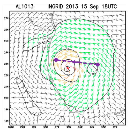
Figure 8.
Overlay display of HIWRAP flight observation path and Multiplatform Satellite Surface Wind Analysis product.
4.2. Retrieval Results and Validation
Figure 9 shows the vertical cross section of reflectivity and radial velocity data obtained from the HIWRAP observations along the flight from 18:34 to 19:14 UTC 15 September 2013. The red stripe at the bottom of the reflectivity is the sea surface. We can see that there is a broad stratiform region with a melting band at a height of about 5 km and convection at a distance of about 200 km, which is one of the benefits of using the VAD technique. According to the reflectivity and the flight speed, it could be calculated that the aircraft started to enter the hurricane’s maximum wind circle area at about 175 km along the track.
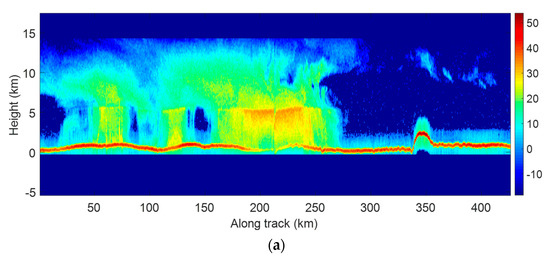
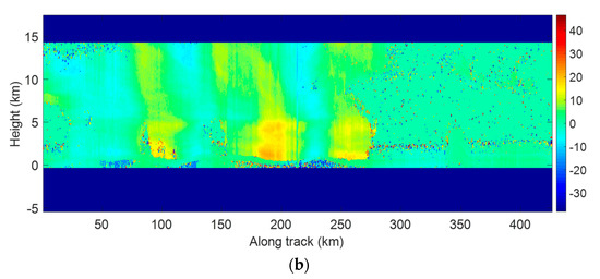
Figure 9.
Vertical cross section of HIWRAP observations of Hurricane Ingrid between 18:34 and 19:14 UTC 15 September 2013. (a) Reflectivity (dBZ); (b) Doppler velocity (m/s).
The wind fields retrieved from HIWRAP data using the proposed VAD method at 13 km under the aircraft platform, i.e., the vertical height of about 5 km since the flight altitude is about 18 km, are shown in Figure 10. Here, we use the MSWA product as shown in Figure 8, which combines information from geostationary and polar satellite data and data from different channels, such as infrared, scatterometer, and microwave probes, to verify the retrieval results [35].
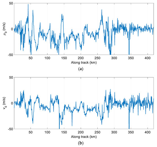
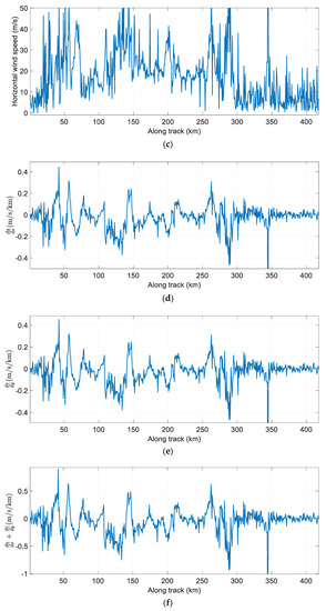
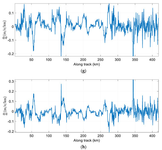
Figure 10.
Wind fields retrieved along the track from the velocity–azimuth display (VAD) analysis at the height of about 5 km. (a) Horizontal wind field component (m/s); (b) Horizontal wind field component (m/s); (c) Horizontal velocity of wind (m/s); (d) Gradient of direction of ,(m/s/km); (e) Gradient of direction of , (m/s/km); (f) Divergence of the horizontal wind,(m/s/km); (g) Gradient of direction of ,(m/s/km); (h) Gradient of direction of , (m/s/km).
Comparing Figure 10c with Figure 8, we can see that the retrieved horizontal wind speed is roughly the same as with MSWA. When the aircraft flies to 50 km along the track, the horizontal wind speed was about 20 m/s. In addition, when the aircraft crosses the hurricane, the horizontal wind speed retrieved by VAD was 30 m/s~50 m/s, which was close to the reference wind speed in Figure 8.
Figure 11 illustrates the retrieved mean vertical profile of the horizontal winds overlaid on the reflectivity at the center of Ingrid. It can be seen that the wind direction is mostly northeast, and the VAD analysis can obtain high-resolution average wind field information in the vertical direction. In addition, according to the MSWA product shown in Figure 8, it could be determined that the northeast wind prevailed when the aircraft flew toward the hurricane body. The above analysis of the average horizontal wind speed and wind direction shows that the SVAD wind field retrieval method derived in this paper can be used in the conical scanning downward observation, and the retrieval results are credible.
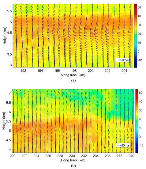
Figure 11.
Retrieved horizontal wind vector overlaid on HIWRAP reflectivity. (a) Vertical profile of the horizontal winds from 192 km to 204 km along the track; (b) Vertical profile of the horizontal winds from 220 km to 240 km along the track.
5. Discussion
VAD was originally created for ground-based Doppler radar to retrieve wind field data, due to low computation and real-time performance [21]. However, the high-speed motion of satellites makes wind field inversions extraordinarily complex for spaceborne radar. Due to the high-speed flight of the spaceborne radar, the first step of the Taylor series expansion of the wind field is changed by comparing it with a ground-based stationary platform, which affects the determination of the VAD coefficients at all levels. In order to compensate for the motion of the satellite, we derived the harmonic coefficients by azimuth integration using the third harmonic of the azimuth angle, and the 3D wind field and gradients in all directions were obtained.
In this section, we compare our approach with the classic VAD method as described in [21,24]. For , , the harmonic coefficients are given as , , , , and . Then, the standard VAD could only provide the horizontal wind field as , . Both the simulated uniform and linear wind fields as described in Section 2 were used to analyze the two methods. The root mean square error (RMSE) is calculated as , where and are the retrieved and real wind vectors, respectively, and N is the number of evaluation measurements. The 100 averaged RMSEs of the two methods for the uniform and linear wind field retrievals are summarized in Table 5 and Table 6, respectively.

Table 5.
Performance comparison between the spaceborne version of the velocity–azimuth display (SVAD) and VAD, for uniform wind field.

Table 6.
Performance comparison between the SVAD and VAD, for linear wind field.
It can be seen from the Table 5 and Table 6 that the retrieval performance of SVAD for uniform wind fields is not as good as that of the VAD method, and the retrieval accuracy of both methods increases as the SNR increases. Both methods have comparable retrieval capabilities for linear wind fields and are less affected by the SNR. This is determined by the derivation process of SVAD. According to Equation (6), the coefficients are related to the satellite flight speed and the gradient of the wind field. Since the flight velocity of the satellite is relatively large, a large accumulated error can be generated even in the case of a small gradient and high SNR. In contrast, the VAD method ignores the speed of satellite movement, so the error is smaller. However, the VAD method can only obtain the horizontal wind field components, while the SVAD method can retrieve all the components of the wind field and the gradient of the horizontal wind field in different directions. Therefore, the SVAD method has greater advantages in practical applications.
It is also reported that the error of (along track wind) is relatively small, but the accuracy of (cross-track wind) is sensitive to SNR. To address this issue, we rewrite the equation of wind retrieval as
where
By comparing the coefficient of the last term of integration in the above equations, the coefficient for is and the coefficient of is −4, hence the error for will be larger according to the error propagation principle. According to the observing system’s capability analysis and review by the world meteorological office (WMO) [11], the threshold of the horizontal wind error is 5 m/s in the lower troposphere for global numerical weather prediction. Our results reveal that the proposed SVAD has potential use in future spaceborne Doppler precipitation and rain radar.
The wind field retrieved by VAD represented the average value of a certain region within the radar scanning range and many instantaneous or small-scale features were smoothed, therefore, convection with a scale smaller than the scanning area of a circle was impossible to capture, and only large mesoscale and large-scale weather features were retained. Spaceborne radar has a unique advantage for large-scale uniform linear wind field observation due to its large swath width, hence, the VAD technique has good prospects in the wind field retrieval of spaceborne radar.
The limit of our work is the lack of dropsonde data, so the wind field retrieved from the existing airborne radar data is only qualitatively analyzed and the retrieval error could not be quantitatively analyzed. In order to quantitatively verify the effectiveness of the proposed wind field retrieval method, airborne radar and a dropsonde joint observation experiment should be implemented in future work.
6. Conclusions
To retrieve the horizontal wind field with high vertical resolution over a large observation swath from a spaceborne platform, this article developed for the first time a spaceborne version of the velocity–azimuth display technique for wind field retrieval. After establishing the space geometry observation model, the VAD wind field retrieval method under the spaceborne platform was derived. Different from the existing methods, the influence of the high-speed motion of the satellite on the VAD method was studied in this article. It was found that a product term of azimuth angle and its first harmonic was introduced to the radial velocity of the conical scanning spaceborne radar, and by using the third harmonic, the coefficients of the product term were deduced. In addition, the influence of satellite heading angle on the VAD method was considered in this paper so as to facilitate the practical application of the spaceborne cloud and rain radar wind field retrieval.
The main conclusions are drawn as follows: First, the variation curve of radial velocity of the uniform wind field obtained by the conical scanning strategy with azimuth angle is no longer a regular trigonometric function under the satellite platform. Second, for the simulated uniform wind field, the VAD provides a mean vertical profile of the horizontal winds with high vertical resolution, which is close to the real value, but the vertical component error is large. This is because the calculation of the vertical wind field component is related to the flight speed of the satellite and the gradient of horizontal wind field in different directions, so the accumulated transmission error is large. Third, for the airborne radar data, the proposed method cannot be used to obtain the detailed internal structure of the hurricane but can successfully capture the average wind field. The retrieved average horizontal wind speed and direction are consistent with the Multiplatform Satellite Surface Wind Analysis product, which has positive and important reference values for data assimilation and operational prediction of storm location and intensity.
In order to evaluate the performance of the proposed method, the simulated uniform and linear wind fields were used. Furthermore, the real airborne radar data of HIWRAP with the same conical scanning downward view was used for validation, and a qualitative analysis of the retrieval results compared with historical wind field data was carried out. Simulated and real data retrieval results proved that the proposed spaceborne version of the VAD technique was robust and effective and could be used to retrieve the mean wind field of future spaceborne radar.
Author Contributions
Conceptualization, Y.W. and M.W.; methodology, Y.W.; formal analysis, M.W. and Q.S.; validation, Y.W. and Q.S.; investigation, Y.W. and M.W.; writing—original draft preparation, Y.W.; writing—review and editing, M.W. and Q.S.; supervision, M.W. and Q.S.; funding acquisition, Q.S. All authors have read and agreed to the published version of the manuscript.
Funding
This work was funded by the National Natural Science Foundation of China (42005100, 41675028), the Scientific Research Start-up Foundation for Talent Introduction of Nantong University (19R87), and the Shanghai Aerospace Science and Technology Innovation Fund Project (SAST2019-097).
Acknowledgments
We are very thankful to the NASA HS3 mission and Gerry Heymsfield’s team for providing free and open access to the HIWRAP data. We also owe great thanks to the editor and all three anonymous reviewers for their generous time in providing detailed comments and informative suggestions that helped us to improve the paper.
Conflicts of Interest
The authors declare no conflict of interest.
References
- Probert-Jones, J.R. Meteorological use of pulsed Doppler radar. Nature 1960, 186, 271–273. [Google Scholar] [CrossRef]
- Baker, W.E.; Atlas, R.; Cardinali, C.; Clement, A.; Emmitt, G.D.; Gentry, B.M.; Hardesty, R.M.; Källén, E.; Kavaya, M.J.; Langland, R.; et al. Lidar-measured wind profiles: The missing link in the global observing system. Bull. Am. Meteorol. Soc. 2014, 95, 543–564. [Google Scholar] [CrossRef]
- Duan, B.; Zhang, W.; Yang, X.; Dai, H.; Yu, Y. Assimilation of Typhoon Wind Field Retrieved from Scatterometer and SAR Based on the Huber Norm Quality Control. Remote Sens. 2017, 9, 987. [Google Scholar] [CrossRef]
- Zhang, W. The vision of space-based component of WMO Integrated Global Observing Systems (WIGOS) in 2040—Anticipating requirements and new space technologies. In Proceedings of the 2016 EUMETSAT Meteorological Satellite Conference, Darmstadt, Germany, 26–30 September 2016. [Google Scholar]
- Hu, T.; Li, Y.; Li, Y.; Wu, Y.; Zhang, D. Retrieval of Sea Surface Wind Fields Using Multi-Source Remote Sensing Data. Remote Sens. 2020, 12, 1482. [Google Scholar] [CrossRef]
- Liu, H.; Jin, S.; Yan, Q. Evaluation of the Ocean Surface Wind Speed Change following the Super Typhoon from Space-Borne GNSS-Reflectometry. Remote Sens. 2020, 12, 2034. [Google Scholar] [CrossRef]
- WMO. GCOS, Systematic Observation Requirements for Satellite-Based Products for Climate. WMO Repoter GCOS-107. 2006. Available online: https://library.wmo.int/doc_num.php?explnum_id=3813 (accessed on 1 September 2006).
- Illingworth, A.J.; Barker, H.W.; Beljaars, A. The EarthCARE Satellite: The Next Step Forward in Global Measurements of Clouds, Aerosols, Precipitation, and Radiation. Bull. Am. Meteorol. Soc. 2014, 31, 197–210. [Google Scholar] [CrossRef]
- Lemaître, Y.; Viltard, N. 3D wind field retrieval from spaceborne Doppler radar. In Remote Sensing of the Atmosphere, Clouds, and Precipitation IV; International Society for Optics and Photonics: New York, NY, USA, 2012; Volume 8523, p. 85230Q. [Google Scholar]
- Taveneau, N.; Caubet, E.; Richard, J.; Lorenzo, J.; Albouys, V.; Souyris, J.C.; Viltard, N.; Lemaitre, Y. A spaceborne Doppler radar for 3D winds mapping inside clouds. In Proceedings of the 2011 IEEE International Geoscience and Remote Sensing Symposium, Vancouver, BC, Canada, 24–29 July 2011; pp. 2721–2724. [Google Scholar]
- Illingworth, A.J.; Battaglia, A.; Bradford, J.; Forsythe, M.; Joe, P.; Kollias, P.; Lean, K.; Lori, M.; Mahfouf, J.F.; Melo, S.; et al. WIVERN: A new satellite concept to provide global in-cloud winds, precipitation, and cloud properties. Bull. Am. Meteorol. Soc. 2018, 99, 1669–1687. [Google Scholar] [CrossRef]
- Wang, Y.X.; Wei, M.; Wang, Z.H.; Zhang, S.; Liu, L.X. Novel scanning strategy for future spaceborne Doppler weather radar with application to tropical cyclones. IEEE J. Sel. Top. Appl. Earth Obs. Remote Sens. 2017, 10, 2685–2693. [Google Scholar] [CrossRef]
- Teschke, G.; Lehmann, V. Mean wind vector estimation using the velocity–azimuth display (VAD) method: An explicit algebraic solution. Atmos. Meas. Tech. 2017, 10, 3265–3271. [Google Scholar] [CrossRef]
- Lee, W.C.; Tang, X.; Jou, B.J.D. Distance velocity–azimuth display (DVAD)—New interpretation and analysis of Doppler velocity. Mon. Weather Rev. 2014, 142, 573–589. [Google Scholar] [CrossRef][Green Version]
- Klazura, G.E.; Imy, D.A. A Description of the Initial Set of Analysis Products Available from the NEXRAD WSR-88D System. Bull. Am. Meteorol. Soc. 1993, 74, 1293–1312. [Google Scholar] [CrossRef]
- Crum, T.D.; Alberty, R.L. The WSR-88D and the WSR-88D operational support facility. Bull. Am. Meteorol. Soc. 1993, 74, 1669–1688. [Google Scholar] [CrossRef]
- Illingworth, A.J.; Cimini, D.; Gaffard, C. Exploiting Existing Ground-Based Remote Sensing Networks to Improve High-Resolution Weather Forecasts. Bull. Am. Meteorol. Soc. 2015, 96, 2107–2125. [Google Scholar] [CrossRef]
- Ma, Q.Y.; Li, Z.C.; Tao, S.W. Wind field retrieval through single Doppler weather radar and its application to NWP. J. Appl. Meteorol. Sci. 2001, 12, 488–493. [Google Scholar]
- Kelberlau, F.; Mann, J. Better turbulence spectra from velocity–azimuth display scanning wind lidar. Atmos. Meas. Tech. 2019, 12, 1871–1888. [Google Scholar] [CrossRef]
- Lhermitte, R.M.; Atlas, D. Precipitation motion by pulse Doppler radar. In Proceedings of the 9th Weather Radar Conf., Kansas, MO, USA, 23–26 October 1961; pp. 218–223. [Google Scholar]
- Browning, K.A.; Wexler, R. The determination of kinematic properties of a wind field using Doppler radar. J. Appl. Meteorol. 1968, 8, 105–113. [Google Scholar] [CrossRef]
- Srivastava, R.C.; Matejka, T.J.; Lorello, T.J. Doppler radar study of the trailing anvil region associated with a squall line. J. Atmos. Sci. 1986, 43, 356–377. [Google Scholar] [CrossRef]
- Matejka, T.; Srivastava, R.C. An Improved Version of the Extended Velocity-Azimuth Display Analysis of Single-Doppler Radar Data. J. Atmos. Ocean. Technol. 1991, 8, 453–466. [Google Scholar] [CrossRef]
- Tian, L.; Heymsfield, G.M.; Didlake, A.C. Velocity-Azimuth Display Analysis of Doppler Velocity for HIWRAP. J. Appl. Meteorol. Climatol. 2015, 54, 1792–1808. [Google Scholar] [CrossRef]
- Fernandez, D.E.; Kerr, E.M.; Castells, A.; Carswell, J.R.; Frasier, S.J.; Chang, P.S.; Marks, F.D. IWRAP: The imaging wind and rain airborne profiler for remote sensing of the ocean and the atmospheric boundary layer within tropical cyclones. IEEE Trans. Geosci. Remote Sens. 2005, 43, 1775–1787. [Google Scholar] [CrossRef]
- Guimond, S.R.; Tian, L.; Heymsfield, G.M.; Frasier, S.J. Wind retrieval algorithms for the IWRAP and HIWRAP airborne Doppler radars with applications to hurricanes. J. Atmos. Ocean. Technol. 2014, 31, 1189–1215. [Google Scholar] [CrossRef]
- Didlake, A.C.; Heymsfield, G.M.; Tian, L.; Guimond, S.R. The coplane analysis technique for three-dimensional wind retrieval using the HIWRAP airborne Doppler radar. J. Appl. Meteorol. Climatol. 2015, 54, 605–623. [Google Scholar] [CrossRef][Green Version]
- Miao, Y.; Dong, X.; Bao, Q.; Zhu, D. Perspective of a Ku-Ka Dual-Frequency Scatterometer for Simultaneous Wide-Swath Ocean Surface Wind and Current Measurement. Remote Sens. 2018, 10, 1042. [Google Scholar] [CrossRef]
- Tan, D.G.; Andersson, E.; Kloe, J.D.; Marseille, G.J.; Stoffelen, A.; Poli, P.; Flamant, P. The ADM-Aeolus wind retrieval algorithms. Tellus A Dyn. Meteorol. Oceanogr. 2008, 60, 191–205. [Google Scholar] [CrossRef]
- Li, L.; Heymsfield, G.; Carswell, J.; Schaubert, D.H.; McLinden, M.L.; Creticos, J.; Guimond, S. The NASA high-altitude imaging wind and rain airborne profiler. IEEE Trans. Geosci. Remote Sens. 2016, 54, 298–310. [Google Scholar] [CrossRef]
- Braun, S.A.; Newman, P.A.; Heymsfield, G.M. NASA’s Hurricane and Severe Storm Sentinel (HS3) Investigation. Bull. Am. Meteorol. Soc. 2016, 97, 2085–2102. [Google Scholar] [CrossRef]
- Heymsfield, G.M.; Tian, L. Hurricane and Severe Storm Sentinel (HS3) High-Altitude Imaging Wind & Rain Airborne Profiler (HIWRAP) [Indicate Subset Used]; NASA EOSDIS Global Hydrology Resource Center Distributed Active Archive Center: Huntsville, AL, USA, 2015. Available online: http://dx.doi.org/10.5067/HS3/HIWRAP/DATA101 (accessed on 27 October 2015).
- Beven, J.L.; National Hurricane Center Tropical Cyclone Report Hurricane INGRID (AL102013). National Hurricane Center. 2014. Available online: https://www.nhc.noaa.gov/data/tcr/AL102013_Ingrid.pdf (accessed on 14 April 2014).
- NOAA Satellites and Information. AL102013—Hurricane INGRID Multiplatform Satellite Surface Wind Analysis (Experimental) [EB/OL]. Available online: https://rammb-data.cira.colostate.edu/tc_realtime/archive_sub_products.asp?product=mpsatwnd&storm_identifier=al102013 (accessed on 15 September 2013).
- Atlas, R.; Hoffman, R.N.; Ardizzone, J.; Leidner, S.M.; Jusem, J.C.; Smith, D.K.; Gombos, D. A cross-calibrated, multiplatform ocean surface wind velocity product for meteorological and oceanographic applications. Bull. Am. Meteorol. Soc. 2011, 92, 157–174. [Google Scholar] [CrossRef]
© 2020 by the authors. Licensee MDPI, Basel, Switzerland. This article is an open access article distributed under the terms and conditions of the Creative Commons Attribution (CC BY) license (http://creativecommons.org/licenses/by/4.0/).