DNA-Based Super-Resolution Microscopy: DNA-PAINT


Abstract
1. Introduction
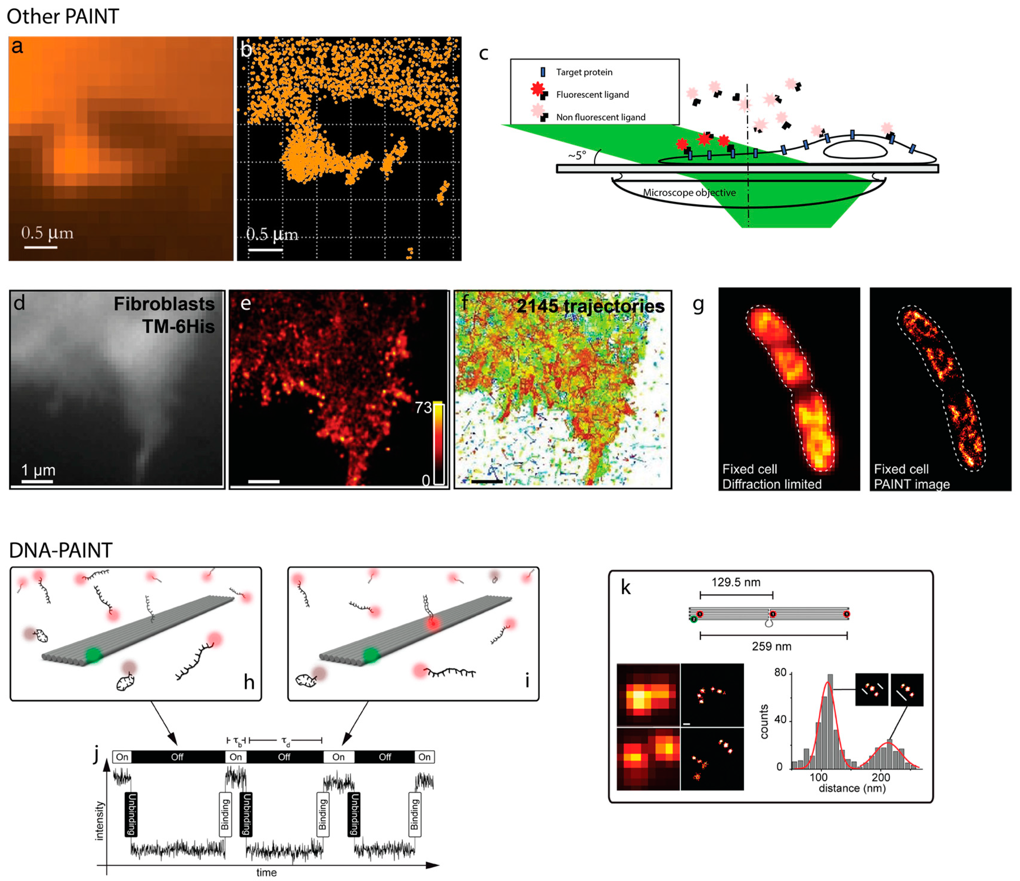
2. PAINT
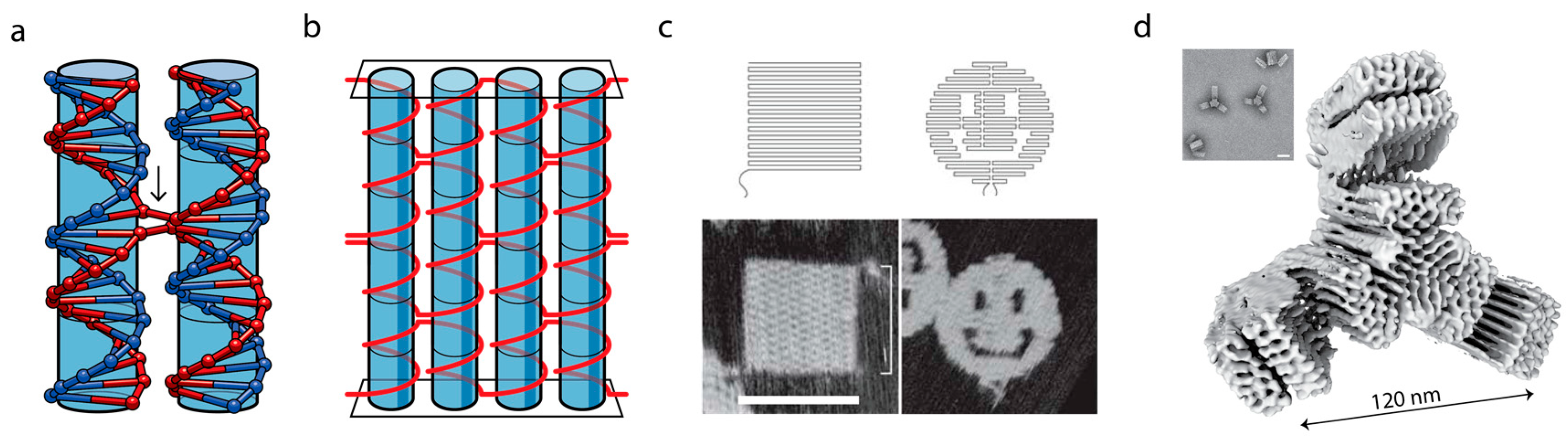
3. DNA as a Programmable Polymer
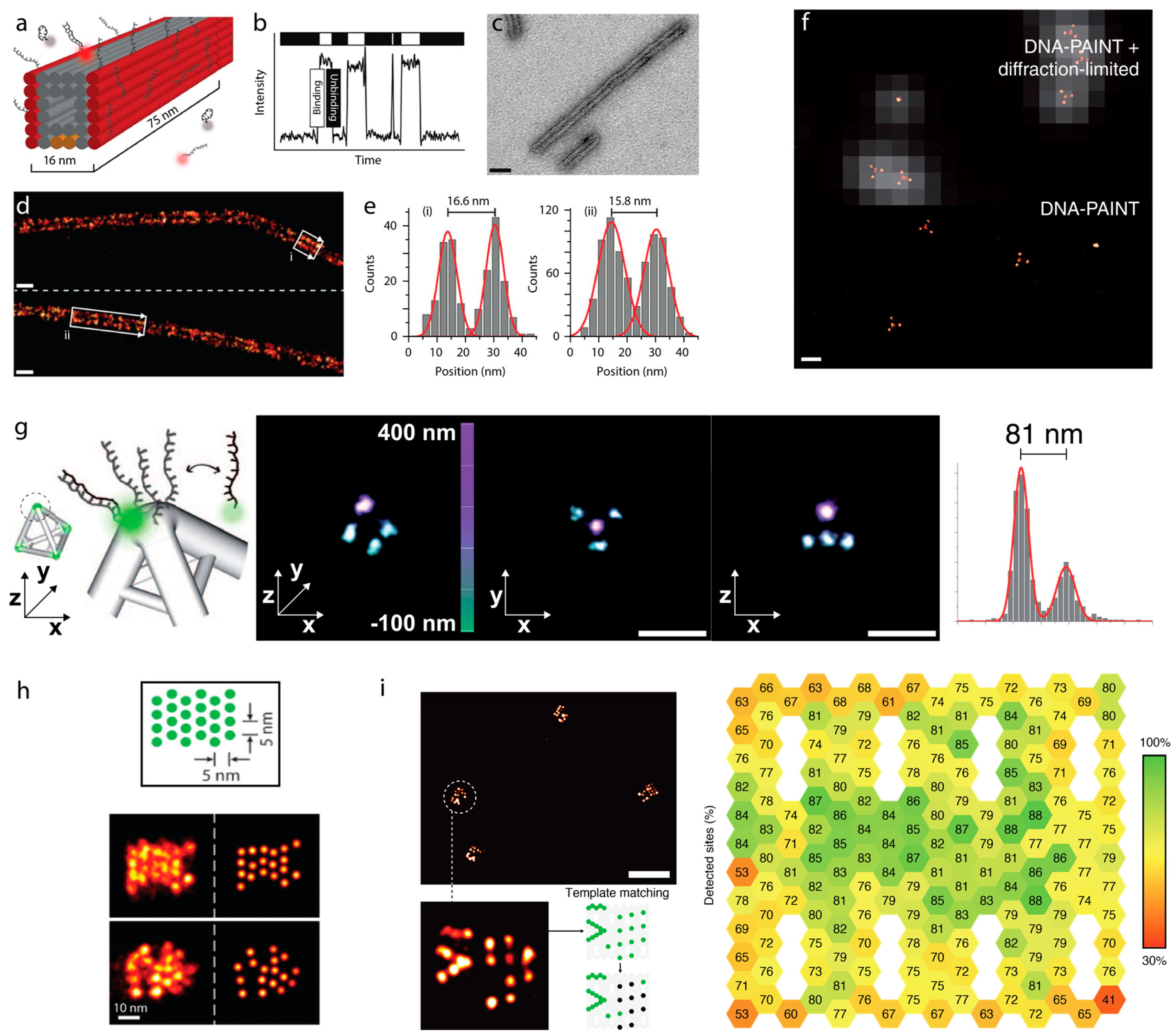
4. Sub-Diffraction Imaging of DNA Origami via DNA-PAINT
5. Counting Molecules/DNA-Docking Strands—Quantitative DNA-PAINT (qPAINT)
6. Exchange PAINT
7. FRET-PAINT
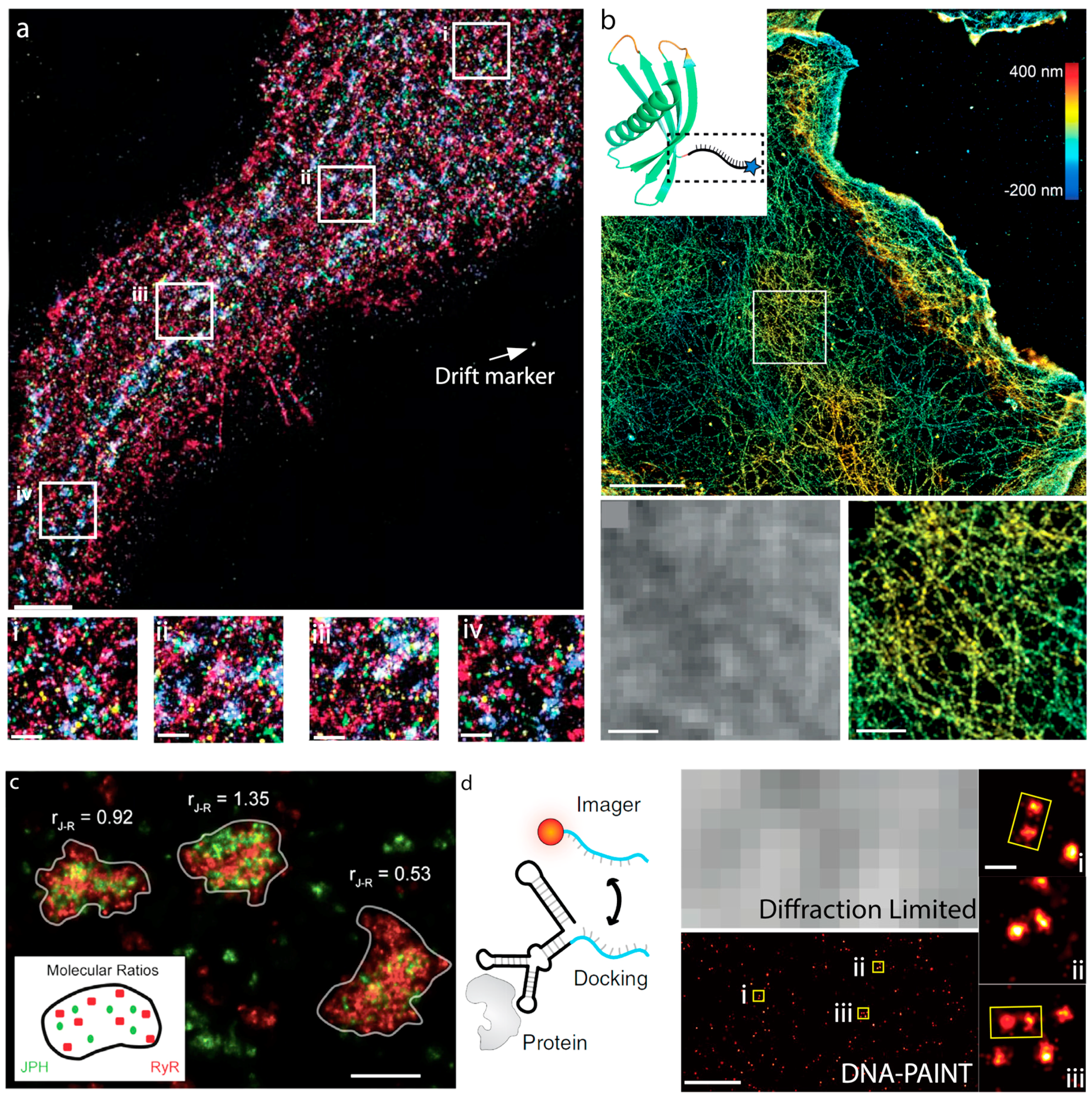
8. Cellular Imaging via DNA-PAINT
Current Challenges in DNA-PAINT
9. Conclusions
Author Contributions
Funding
Conflicts of Interest
References
- Chalfie, M.; Tu, Y.; Euskirchen, G.; Ward, W.W.; Prasher, D.C. Green fluorescent protein as a marker for gene expression. Science 1994, 263, 802–805. [Google Scholar] [CrossRef] [PubMed]
- Betzig, E. Single Molecules, cells, and super-resolution optics (Nobel Lecture). Angew. Chem. Int. Ed. Engl. 2015, 54, 8034–8053. [Google Scholar] [CrossRef] [PubMed]
- Hell, S.W. Nanoscopy with focused light (Nobel Lecture). Angew. Chem. Int. Ed. Engl. 2015, 54, 8054–8066. [Google Scholar] [CrossRef] [PubMed]
- Moerner, W.E. Single-molecule spectroscopy, imaging, and photocontrol: Foundations for super-resolution microscopy (Nobel Lecture). Angew. Chem. Int. Ed. Engl. 2015, 54, 8067–8093. [Google Scholar] [CrossRef] [PubMed]
- Betzig, E.; Patterson, G.H.; Sougrat, R.; Lindwasser, O.W.; Olenych, S.; Bonifacino, J.S.; Davidson, M.W.; Lippincott-Schwartz, J.; Hess, H.F. Imaging intracellular fluorescent proteins at nanometer resolution. Science 2006, 313, 1642–1645. [Google Scholar] [CrossRef] [PubMed]
- McKinney, S.A.; Murphy, C.S.; Hazelwood, K.L.; Davidson, M.W.; Looger, L.L. A bright and photostable photoconvertible fluorescent protein. Nat. Methods 2009, 6, 131–133. [Google Scholar] [CrossRef] [PubMed]
- Rust, M.J.; Bates, M.; Zhuang, X. Sub-diffraction-limit imaging by stochastic optical reconstruction microscopy (STORM). Nat. Methods 2006, 3, 793–795. [Google Scholar] [CrossRef] [PubMed]
- Heilemann, M.; van de Linde, S.; Schuttpelz, M.; Kasper, R.; Seefeldt, B.; Mukherjee, A.; Tinnefeld, P.; Sauer, M. Subdiffraction-resolution fluorescence imaging with conventional fluorescent probes. Angew. Chem. Int. Ed. Engl. 2008, 47, 6172–6176. [Google Scholar] [CrossRef]
- Dempsey, G.T.; Vaughan, J.C.; Chen, K.H.; Zhuang, X.W. Evaluation of fluorophores for optimal performance in localization-based super-resolution imaging. Biophys. J. 2012, 102, 725a. [Google Scholar] [CrossRef]
- Sharonov, A.; Hochstrasser, R.M. Wide-field subdiffraction imaging by accumulated binding of diffusing probes. Proc. Natl. Acad. Sci. USA 2006, 103, 18911–18916. [Google Scholar] [CrossRef]
- Giannone, G.; Hosy, E.; Levet, F.; Constals, A.; Schulze, K.; Sobolevsky, A.I.; Rosconi, M.P.; Gouaux, E.; Tampe, R.; Choquet, D.; et al. Dynamic superresolution imaging of endogenous proteins on living cells at ultra-high density. Biophys. J. 2010, 99, 1303–1310. [Google Scholar] [CrossRef] [PubMed]
- Winckler, P.; Lartigue, L.; Giannone, G.; De Giorgi, F.; Ichas, F.; Sibarita, J.B.; Lounis, B.; Cognet, L. Identification and super-resolution imaging of ligand-activated receptor dimers in live cells. Sci. Rep. 2013, 3, 2387. [Google Scholar] [CrossRef] [PubMed]
- Ries, J.; Kaplan, C.; Platonova, E.; Eghlidi, H.; Ewers, H. A simple, versatile method for GFP-based super-resolution microscopy via nanobodies. Nat. Methods 2012, 9, 582–584. [Google Scholar] [CrossRef] [PubMed]
- Nair, D.; Hosy, E.; Petersen, J.D.; Constals, A.; Giannone, G.; Choquet, D.; Sibarita, J.B. Super-resolution imaging reveals that AMPA receptors inside synapses are dynamically organized in nanodomains regulated by PSD95. J. Neurosci. 2013, 33, 13204–13224. [Google Scholar] [CrossRef] [PubMed]
- Spahn, C.K.; Glaesmann, M.; Grimm, J.B.; Ayala, A.X.; Lavis, L.D.; Heilemann, M. A toolbox for multiplexed super-resolution imaging of the E. coli nucleoid and membrane using novel PAINT labels. Sci. Rep. 2018, 8, 14768. [Google Scholar] [CrossRef] [PubMed]
- Grimm, J.B.; Muthusamy, A.K.; Liang, Y.; Brown, T.A.; Lemon, W.C.; Patel, R.; Lu, R.; Macklin, J.J.; Keller, P.J.; Ji, N.; et al. A general method to fine-tune fluorophores for live-cell and in vivo imaging. Nat. Methods 2017, 14, 987–994. [Google Scholar] [CrossRef] [PubMed]
- Jungmann, R.; Steinhauer, C.; Scheible, M.; Kuzyk, A.; Tinnefeld, P.; Simmel, F.C. Single-molecule kinetics and super-resolution microscopy by fluorescence imaging of transient binding on DNA origami. Nano Lett. 2010, 10, 4756–4761. [Google Scholar] [CrossRef]
- Bednar, J.; Furrer, P.; Katritch, V.; Stasiak, A.Z.; Dubochet, J.; Stasiak, A. Determination of DNA persistence length by cryo-electron microscopy. Separation of the static and dynamic contributions to the apparent persistence length of DNA. J. Mol. Biol. 1995, 254, 579–594. [Google Scholar] [CrossRef]
- Caruthers, M.H. Gene synthesis machines: DNA chemistry and its uses. Science 1985, 230, 281–285. [Google Scholar] [CrossRef]
- Bandy, T.J.; Brewer, A.; Burns, J.R.; Marth, G.; Nguyen, T.; Stulz, E. DNA as supramolecular scaffold for functional molecules: Progress in DNA nanotechnology. Chem. Soc. Rev. 2011, 40, 138–148. [Google Scholar] [CrossRef]
- Seeman, N.C. Nucleic acid junctions and lattices. J. Theor. Biol. 1982, 99, 237–247. [Google Scholar] [CrossRef]
- Baker, M.A.B.; Tuckwell, A.J.; Berengut, J.F.; Bath, J.; Benn, F.; Duff, A.P.; Whitten, A.E.; Dunn, K.E.; Hynson, R.M.; Turberfield, A.J.; et al. Dimensions and global twist of single-layer DNA origami measured by small-angle X-ray scattering. ACS Nano 2018. [Google Scholar] [CrossRef] [PubMed]
- Rothemund, P.W. Folding DNA to create nanoscale shapes and patterns. Nature 2006, 440, 297–302. [Google Scholar] [CrossRef] [PubMed]
- Wagenbauer, K.F.; Sigl, C.; Dietz, H. Gigadalton-scale shape-programmable DNA assemblies. Nature 2017, 552, 78. [Google Scholar] [CrossRef] [PubMed]
- Chen, J.H.; Seeman, N.C. Synthesis from DNA of a molecule with the connectivity of a cube. Nature 1991, 350, 631–633. [Google Scholar] [CrossRef] [PubMed]
- Goodman, R.P.; Schaap, I.A.; Tardin, C.F.; Erben, C.M.; Berry, R.M.; Schmidt, C.F.; Turberfield, A.J. Rapid chiral assembly of rigid DNA building blocks for molecular nanofabrication. Science 2005, 310, 1661–1665. [Google Scholar] [CrossRef]
- Yurke, B.; Turberfield, A.J.; Mills, A.P., Jr.; Simmel, F.C.; Neumann, J.L. A DNA-fuelled molecular machine made of DNA. Nature 2000, 406, 605–608. [Google Scholar] [CrossRef]
- Bath, J.; Green, S.J.; Turberfield, A.J. A free-running DNA motor powered by a nicking enzyme. Angew. Chem. Int. Ed. Engl. 2005, 44, 4358–4361. [Google Scholar] [CrossRef]
- Macfarlane, R.J.; Lee, B.; Jones, M.R.; Harris, N.; Schatz, G.C.; Mirkin, C.A. Nanoparticle superlattice engineering with DNA. Science 2011, 334, 204–208. [Google Scholar] [CrossRef]
- Seelig, G.; Soloveichik, D.; Zhang, D.Y.; Winfree, E. Enzyme-free nucleic acid logic circuits. Science 2006, 314, 1585–1588. [Google Scholar] [CrossRef]
- Delebecque, C.J.; Lindner, A.B.; Silver, P.A.; Aldaye, F.A. Organization of intracellular reactions with rationally designed RNA assemblies. Science 2011, 333, 470–474. [Google Scholar] [CrossRef] [PubMed]
- Douglas, S.M.; Bachelet, I.; Church, G.M. A logic-gated nanorobot for targeted transport of molecular payloads. Science 2012, 335, 831–834. [Google Scholar] [CrossRef] [PubMed]
- Zhang, D.Y.; Seelig, G. Dynamic DNA nanotechnology using strand-displacement reactions. Nat. Chem. 2011, 3, 103–113. [Google Scholar] [CrossRef] [PubMed]
- Speicher, M.R.; Gwyn Ballard, S.; Ward, D.C. Karyotyping human chromosomes by combinatorial multi-fluor FISH. Nat. Genet. 1996, 12, 368–375. [Google Scholar] [CrossRef] [PubMed]
- Volpi, E.V.; Bridger, J.M. FISH glossary: An overview of the fluorescence in situ hybridization technique. Biotechniques 2008, 45, 385–409. [Google Scholar] [CrossRef] [PubMed]
- Markaki, Y.; Smeets, D.; Cremer, M.; Schermelleh, L. Fluorescence in situ hybridization applications for super-resolution 3D structured illumination microscopy. Methods Mol. Biol. 2013, 950, 43–64. [Google Scholar] [CrossRef] [PubMed]
- Jungmann, R.; Avendano, M.S.; Dai, M.; Woehrstein, J.B.; Agasti, S.S.; Feiger, Z.; Rodal, A.; Yin, P. Quantitative super-resolution imaging with qPAINT. Nat. Methods 2016, 13, 439–442. [Google Scholar] [CrossRef] [PubMed]
- Auer, A.; Strauss, M.T.; Schlichthaerle, T.; Jungmann, R. Fast, background-free DNA-PAINT imaging using FRET-based probes. Nano Lett. 2017, 17, 6428–6434. [Google Scholar] [CrossRef] [PubMed]
- Jungmann, R.; Avendano, M.S.; Woehrstein, J.B.; Dai, M.; Shih, W.M.; Yin, P. Multiplexed 3D cellular super-resolution imaging with DNA-PAINT and Exchange-PAINT. Nat. Methods 2014, 11, 313–318. [Google Scholar] [CrossRef] [PubMed]
- Schueder, F.; Strauss, M.T.; Hoerl, D.; Schnitzbauer, J.; Schlichthaerle, T.; Strauss, S.; Yin, P.; Harz, H.; Leonhardt, H.; Jungmann, R. Universal super-resolution multiplexing by DNA exchange. Angew. Chem. Int. Ed. Engl. 2017, 56, 4052–4055. [Google Scholar] [CrossRef] [PubMed]
- Iinuma, R.; Ke, Y.; Jungmann, R.; Schlichthaerle, T.; Woehrstein, J.B.; Yin, P. Polyhedra self-assembled from DNA tripods and characterized with 3D DNA-PAINT. Science 2014, 344, 65–69. [Google Scholar] [CrossRef] [PubMed]
- Steinhauer, C.; Jungmann, R.; Sobey, T.L.; Simmel, F.C.; Tinnefeld, P. DNA origami as a nanoscopic ruler for super-resolution microscopy. Angew. Chem. Int. Ed. Engl. 2009, 48, 8870–8873. [Google Scholar] [CrossRef] [PubMed]
- Raab, M.; Schmied, J.J.; Jusuk, I.; Forthmann, C.; Tinnefeld, P. Fluorescence microscopy with 6 nm resolution on DNA origami. Chemphyschem 2014, 15, 2431–2435. [Google Scholar] [CrossRef] [PubMed]
- Dai, M.; Jungmann, R.; Yin, P. Optical imaging of individual biomolecules in densely packed clusters. Nat. Nanotechnol. 2016, 11, 798–807. [Google Scholar] [CrossRef] [PubMed]
- Strauss, M.T.; Schueder, F.; Haas, D.; Nickels, P.C.; Jungmann, R. Quantifying absolute addressability in DNA origami with molecular resolution. Nat. Commun. 2018, 9, 1600. [Google Scholar] [CrossRef] [PubMed]
- Mucksch, J.; Blumhardt, P.; Strauss, M.T.; Petrov, E.P.; Jungmann, R.; Schwille, P. Quantifying reversible surface binding via surface-integrated fluorescence correlation spectroscopy. Nano Lett. 2018, 18, 3185–3192. [Google Scholar] [CrossRef] [PubMed]
- Jayasinghe, I.; Clowsley, A.H.; Lin, R.; Lutz, T.; Harrison, C.; Green, E.; Baddeley, D.; Di Michele, L.; Soeller, C. True molecular scale visualization of variable clustering properties of ryanodine receptors. Cell Rep. 2018, 22, 557–567. [Google Scholar] [CrossRef]
- Werbin, J.L.; Avendano, M.S.; Becker, V.; Jungmann, R.; Yin, P.; Danuser, G.; Sorger, P.K. Multiplexed Exchange-PAINT imaging reveals ligand-dependent EGFR and Met interactions in the plasma membrane. Sci. Rep. 2017, 7, 12150. [Google Scholar] [CrossRef]
- Lee, J.; Park, S.; Kang, W.; Hohng, S. Accelerated super-resolution imaging with FRET-PAINT. Mol. Brain 2017, 10, 63. [Google Scholar] [CrossRef]
- Deussner-Helfmann, N.S.; Auer, A.; Strauss, M.T.; Malkusch, S.; Dietz, M.S.; Barth, H.D.; Jungmann, R.; Heilemann, M. Correlative single-molecule FRET and DNA-PAINT imaging. Nano Lett. 2018, 18, 4626–4630. [Google Scholar] [CrossRef]
- Wang, Y.; Woehrstein, J.B.; Donoghue, N.; Dai, M.; Avendano, M.S.; Schackmann, R.C.J.; Zoeller, J.J.; Wang, S.S.H.; Tillberg, P.W.; Park, D.; et al. Rapid sequential in situ multiplexing with DNA exchange imaging in neuronal cells and tissues. Nano Lett. 2017, 17, 6131–6139. [Google Scholar] [CrossRef] [PubMed]
- Schueder, F.; Lara-Gutierrez, J.; Beliveau, B.J.; Saka, S.K.; Sasaki, H.M.; Woehrstein, J.B.; Strauss, M.T.; Grabmayr, H.; Yin, P.; Jungmann, R. Multiplexed 3D super-resolution imaging of whole cells using spinning disk confocal microscopy and DNA-PAINT. Nat. Commun. 2017, 8, 2090. [Google Scholar] [CrossRef] [PubMed]
- Beliveau, B.J.; Boettiger, A.N.; Avendano, M.S.; Jungmann, R.; McCole, R.B.; Joyce, E.F.; Kim-Kiselak, C.; Bantignies, F.; Fonseka, C.Y.; Erceg, J.; et al. Single-molecule super-resolution imaging of chromosomes and in situ haplotype visualization using Oligopaint FISH probes. Nat. Commun. 2015, 6, 7147. [Google Scholar] [CrossRef] [PubMed]
- Beliveau, B.J.; Boettiger, A.N.; Nir, G.; Bintu, B.; Yin, P.; Zhuang, X.; Wu, C.T. In situ super-resolution imaging of genomic DNA with OligoSTORM and OligoDNA-PAINT. Methods Mol. Biol. 2017, 1663, 231–252. [Google Scholar] [CrossRef] [PubMed]
- Babcock, H.; Sigal, Y.M.; Zhuang, X. A high-density 3D localization algorithm for stochastic optical reconstruction microscopy. Opt. Nanoscopy 2012, 1. [Google Scholar] [CrossRef] [PubMed]
- Park, S.; Kang, W.; Kwon, Y.D.; Shim, J.; Kim, S.; Kaang, B.K.; Hohng, S. Superresolution fluorescence microscopy for 3D reconstruction of thick samples. Mol. Brain 2018, 11, 17. [Google Scholar] [CrossRef] [PubMed]
- Moore, R.P.; Legant, W.R. Improving probes for super-resolution. Nat. Methods 2018, 15, 659–660. [Google Scholar] [CrossRef]
- Nikic, I.; Estrada Girona, G.; Kang, J.H.; Paci, G.; Mikhaleva, S.; Koehler, C.; Shymanska, N.V.; Ventura Santos, C.; Spitz, D.; Lemke, E.A. Debugging eukaryotic genetic code expansion for site-specific click-PAINT super-resolution microscopy. Angew. Chem. Int. Ed. Engl. 2016, 55, 16172–16176. [Google Scholar] [CrossRef]
- Nikic-Spiegel, I. Genetic code expansion- and click chemistry-based site-specific protein labeling for intracellular DNA-PAINT imaging. Methods Mol. Biol. 2018, 1728, 279–295. [Google Scholar] [CrossRef]
- Schlichthaerle, T.; Eklund, A.S.; Schueder, F.; Strauss, M.T.; Tiede, C.; Curd, A.; Ries, J.; Peckham, M.; Tomlinson, D.C.; Jungmann, R. Site-specific labeling of affimers for DNA-PAINT microscopy. Angew. Chem. Int. Ed. Engl. 2018. [Google Scholar] [CrossRef]
- Strauss, S.; Nickels, P.C.; Strauss, M.T.; Jimenez Sabinina, V.; Ellenberg, J.; Carter, J.D.; Gupta, S.; Janjic, N.; Jungmann, R. Modified aptamers enable quantitative sub-10-nm cellular DNA-PAINT imaging. Nat. Methods 2018, 15, 685–688. [Google Scholar] [CrossRef] [PubMed]


© 2018 by the authors. Licensee MDPI, Basel, Switzerland. This article is an open access article distributed under the terms and conditions of the Creative Commons Attribution (CC BY) license (http://creativecommons.org/licenses/by/4.0/).
Share and Cite
Nieves, D.J.; Gaus, K.; Baker, M.A.B. DNA-Based Super-Resolution Microscopy: DNA-PAINT. Genes 2018, 9, 621. https://doi.org/10.3390/genes9120621
Nieves DJ, Gaus K, Baker MAB. DNA-Based Super-Resolution Microscopy: DNA-PAINT. Genes. 2018; 9(12):621. https://doi.org/10.3390/genes9120621
Chicago/Turabian StyleNieves, Daniel J., Katharina Gaus, and Matthew A. B. Baker. 2018. "DNA-Based Super-Resolution Microscopy: DNA-PAINT" Genes 9, no. 12: 621. https://doi.org/10.3390/genes9120621
APA StyleNieves, D. J., Gaus, K., & Baker, M. A. B. (2018). DNA-Based Super-Resolution Microscopy: DNA-PAINT. Genes, 9(12), 621. https://doi.org/10.3390/genes9120621