Abstract
This systematic review aimed to analyze the development and functionality of microfluidic concentration gradient generators (CGGs) for toxicological evaluation of different biological organisms. We searched articles using the keywords: concentration gradient generator, toxicity, and microfluidic device. Only 33 of the 352 articles found were included and examined regarding the fabrication of the microdevices, the characteristics of the CGG, the biological model, and the desired results. The main fabrication method was soft lithography, using polydimethylsiloxane (PDMS) material (91%) and SU-8 as the mold (58.3%). New technologies were applied to minimize shear and bubble problems, reduce costs, and accelerate prototyping. The Christmas tree CGG design and its variations were the most reported in the studies, as well as the convective method of generation (61%). Biological models included bacteria and nematodes for antibiotic screening, microalgae for pollutant toxicity, tumor and normal cells for, primarily, chemotherapy screening, and Zebrafish embryos for drug and metal developmental toxicity. The toxic effects of each concentration generated were evaluated mostly with imaging and microscopy techniques. This study showed an advantage of CGGs over other techniques and their applicability for several biological models. Even with soft lithography, PDMS, and Christmas tree being more popular in their respective categories, current studies aim to apply new technologies and intricate architectures to improve testing effectiveness and reduce common microfluidics problems, allowing for high applicability of toxicity tests in different medical and environmental models.
1. Introduction
The toxicological assessment of chemicals, pharmaceuticals, food and food ingredients, cosmetics, and industrial products has significantly advanced due to scientific and technological developments. New techniques, such as the promising alternative of human-cell-seeded organ-on-chips for acute systemic toxicity, as well as in silico approaches, have been replacing conventional techniques, for example, tests which use LD50 as their main parameter, requiring a great number of animals to determine the chemical dose able to achieve 50 percent of deaths [1]. After the 1980s, researchers were encouraged to modify their experimental design strategies in order to reduce, refine, and also replace (3Rs) the conventional methods including animal experimentation. The 3Rs principles led to a dramatic decrease in the use of animals in research and development while also lowering the failure rate of pharmaceuticals [2].
When compared to in vivo studies, in vitro studies demonstrated time and financial savings, high yield, high reproducibility, and fewer ethical concerns [3]. As a result of their advancement and technological innovations, the microfluidic device was able to be created, opening up new possibilities, allowing the association of multiple components, and functioning as a “mini laboratory”, also known as a “lab-on-a-chip”, with possible application in areas such as chemistry, environment, bioenergetics and health [4,5,6].
The fabrication of microfluidic devices requires a set of procedures that enable the development of structures at a micrometric scale with great precision, in order to ensure a laminar flow of fluid in the microchannels [7]. The soft lithography technique is widely used for stamping or micromolding processes due to its ease, effectiveness, and low cost [8]. Complementary techniques, however, have been investigated for the creation of microdevices, which ensures a wider variety of possibilities for the employment of various polymers and structures. These techniques include photolithography and stereolithography [9].
The concentration gradient generator (CGG) is a type of microfluidic device capable of generating a concentration gradient via convection-mixing-based (tree-shape and altered-tree-shape), laminar-flow-diffusion-based (Y-shape), membrane-based, pressure-balance-based, droplet-based, and flow-based methods. All of these different techniques have been proposed and evaluated in a variety of experiments, allowing the study of numerous biological processes, such as cell migration, immunological response, wound healing, cancer invasion and metastasis, inflammation and chemotaxis, and the investigation of the concentration at which an element becomes harmful to an organism [10]. Compared to traditional macroscale evaluation methods, CGG microdevices allow for high analysis performance, with low reagent consumption, more efficient use of samples with limited volumes, a high surface-to-volume ratio, spatio-temporal resolution, portability and easy customization, control, and automation [11,12].
The CGG microdevice technology combines the advantages of microfluidics with a three-dimensional (3D) cell compartment that can preserve the biological complexity of cell models (3D cultures, including microenvironment or vascularization) and mimic drug evaluation, similar to animal models. Many drug candidates in different concentration ranges are evaluated at the same time, and different treatment regimens can also be explored using multiple drug gradient generators and parallel cell culture chambers [13].
The demand for novel medication development is at an all-time high, due to rising drug resistance and the emergence of new diseases, motivating the search for more efficient drug screening methods. The CGG microdevice approach to performing the antimicrobial susceptibility test (AST) is a simple, economic, and fast way to emulate a traditional AST and rapidly provide the minimal inhibitory concentration (MIC) of an antibiotic for a certain bacterial strain, at rates comparable to those of other miniaturized devices and automated AST instruments. The MIC value allows clinicians to prescribe appropriate dosages of the medication and stop bacteria from becoming resistant before being eradicated [14].
In this systematic review, our objective was to investigate how studies have applied micro-CGG for toxicological evaluation and for what purposes, in addition to the technological evolution in the development of these systems. The microfluidic device manufacturing and new technologies applied, the perspective of design and methodology of the CGG system, and the type of biological environment used to evaluate the substance’s toxicity, as well as the outcomes, were considered.
2. Materials and Methods
2.1. Search Strategy
We conducted a systematic search for articles that were published in the previous 10 years, including the years between 2011 and 2022. The articles selected, which are indexed in PubMed and Scopus, followed the Preferred Reporting Items for Systematic Reviews and Meta-Analyses (PRISMA) guidelines [15]. The criteria of interest selected were keywords in the following sequence: ((Concentration Gradient Generator) AND (Toxicity) AND (Microfluidic Device)), using the boolean operators (DecS/MeSH):
SCOPUS: (((TITLE (“organs-on-chips”) OR TITLE (“organs-on-a-chip”) OR TITLE (“microfluidic device”) OR TITLE (“lab-on-chips”) OR TITLE (microfluidics) OR TITLE-ABS-KEY (microfluidic)) AND PUBYEAR > 2010 AND PUBYEAR > 2010) AND ((SRCTITLE (toxicity) OR TITLE (toxicities) OR SRCTITLE (toxicological) OR TITLE (nanotoxicity)) AND PUBYEAR > 2010 AND PUBYEAR > 2010)) OR (((TITLE (“concentration gradient generator”) OR TITLE-ABS-KEY (“microfluidic gradient generator”)) AND PUBYEAR > 2010 AND PUBYEAR > 2010) AND ((TITLE (“organs-on-chips”) OR TITLE (“organs-on-a-chip”) OR TITLE (“microfluidic device”) OR TITLE (“lab-on-chips”) OR TITLE (microfluidics) OR TITLE-ABS-KEY (microfluidic)) AND PUBYEAR > 2010 AND PUBYEAR > 2010))
PubMed: (((TITLE (“concentration gradient generator”) OR TITLE-ABS-KEY (“microfluidic gradient generator”)) AND PUBYEAR > 2010 AND PUBYEAR > 2010) AND ((TITLE (“organs-on-chips”) OR TITLE (“organs-on-a-chip”) OR TITLE (“microfluidic device”) OR TITLE (“lab-on-chips”) OR TITLE (microfluidics) OR TITLE-ABS-KEY (microfluidic)) AND PUBYEAR > 2010 AND PUBYEAR > 2010)] OR (((((((“organs-on-chips”(Title)) OR (“organs-on-a-chip”(Title))) OR (“microfluidic device”(Title))) OR (“lab-on-chips”(Title))) OR (microfluidics(Title))) OR (microfluidic(Title)) AND (2011/1/1:2022/6/1(pdat))) AND ((“Concentration Gradient Generator”(Title/Abstract)) OR (“microfluidic gradient generator”(Title/Abstract)) AND (2011/1/1:2022/6/1(pdat))) Filters: from 1 January 2011 to 6 June 2022)
2.2. Selection Criteria
We only included original articles written in English published within the previous 10 years that used a microfluidic device capable of generating a gradient to analyze the toxicity of different concentrations of a substance to living organisms. The selection factors were in accordance with the PICO criterion we used: Problem: difficulty in generating a linear concentration gradient of a substance quickly and effectively; Intervention: use of microfluidics device to generate gradients; Comparison: to assess substances’ toxicity screening with concentrations generated by CGG and by pipetting; Outcome: toxicity assessment.
2.3. Exclusion Criteria
The following exclusion criteria were used: (i) reviews, (ii) publications written in languages other than English, (iii) indexed articles published in more than one database (duplicates), (iv) only microdevice fabrication protocols, (v) does not assess the toxicity effect in biologic organism, (vi) does not apply toxicology test, and (vii) the microdevice did not employ a concentration gradient generator.
2.4. Data Compilation
In this review, eight of the authors (N.M.E.V., M.P.N., A.H.A., L.D.R., J.B.M., F.A.O., C.S.L., A.T.L., M.N.P.C., and L.F.G.), in pairs, independently and randomly analyzed, reviewed, and assessed the eligibility of titles and abstracts according to the strategy of established search. The authors N.M.E.V., M.P.N., A.H.A., L.D.R., J.B.M., and L.F.G. selected the final articles by evaluating the texts that met the selection criteria. The authors N.M.E.V., L.D.R., J.B.M., F.A.O., C.S.L., and L.F.G. were responsible for the search for the characteristics and fabrication of the CGG with the collaboration and review of the authors A.T.L. and M.N.P.C. The authors N.M.E.V., M.P.N., A.H.A., L.D.R., and L.F.G. searched for the device microenvironment and toxicity techniques. All authors contributed to writing the entire text of this review.
2.5. Data Extraction
Four topics were used to analyze the papers under review, and they were represented in tables that addressed the following features: (1) characteristics, design, and fabrication of concentration gradient generator microfluidic devices for toxicity analyses; (2) microfluidic concentration gradient generators’ characteristics; (3) biological model used for toxicity evaluation; and (4) outcomes of the studies.
2.6. Risk of Bias Assessment
The selection of articles was performed in 2 pairs, and, in case of disagreement, an independent senior author decided on whether the article in question would be included. The data selected in the tables were divided by the authors into the groups already described above, and the checking of the data was carried out by the following group. In the case of disagreement, author L.F.G. made the final decision.
2.7. Data Analysis
The data obtained in each of the tables were analyzed in percentages and range distribution to highlight the main characteristics, particularities, and exceptions, according to applicability.
3. Results
3.1. Selection Process of the Articles Identified According to the PRISMA Guidelines
We searched the PubMed and Scopus databases for publications from the last 10 years, considering the period from 2011 to March 2022 and following the selection inclusion and exclusion criteria already presented, resulting in 352 articles identified, comprising 254 articles from Scopus and 98 from PubMed. Of the 254 articles found in Scopus, 86 were excluded after screening because 31 were reviews, 43 were conference papers, 8 were book chapters, and 4 were not eligible. At screening, 56 articles from PubMed, comprising 47 duplicates and 9 reviews, were also excluded. Eligibility analysis was carried out following the selection criteria, and 139 of the 168 articles from Scopus (45 did not report the organism used in the study, 26 only reported the device development, 30 did not assess toxicity, 17 did not apply the concentration gradient generation in the device, and in 21 the toxicity was assessed outside the device) and 38 from PubMed (8 did not report the organism used in the study, 16 only reported the device development, and 14 did not assess toxicity) were excluded. Thus, only 33 unduplicated full-text articles [16,17,18,19,20,21,22,23,24,25,26,27,28,29,30,31,32,33,34,35,36,37,38,39,40,41,42,43,44,45,46,47,48] were included in this systematic review, 29 from Scopus and 4 from PubMed, as shown in Figure 1.
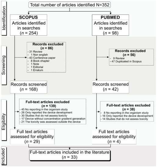
Figure 1.
Schematic representation of the process for articles’ identification, screening, and eligibility for inclusion in this systematic review following the PRISMA guidelines.
The 33 selected studies were analyzed regarding the microdevice fabrication, the CGG characteristics, the biological model, and the main outcomes. Due to the different biological approaches of the selected studies, the tables were organized internally by the four main types of organisms used for toxicity analysis inside of the device: 7 studies used microorganisms (bacteria and nematodes) (21%) [16,17,18,19,20,21,22], 5 used microalgae (15%) [23,24,25,26,27], 19 used tumor cells and other models (58%) [28,29,30,31,32,33,34,35,36,37,38,39,40,41,42,43,44,45,46], and 2 used zebrafish embryos (6%) [47,48].
3.2. Characteristics, Design, and Fabrication of Concentration Gradient Generator Microfluidic Devices for Toxicity Analyses
The technologies utilized in the design, manufacturing, finishing, and innovations of microfluidic devices to generate concentration gradients for toxicological analysis and drug screening in the studies included in this systematic review are summarized in Table 1. General analysis was initially performed regarding the date of publication of the 33 articles with the division performed according to the organisms used for the toxicity assessments (microorganisms, microalgae, tumor cells and other models, or zebrafish embryos), pointing out that in the studies carried out in the last 5 years [16,17,18,19,23,24,28,29,30,31,32,33,34], the use of microorganisms and tumor cells and other models was more prominent, showing a higher incidence and demand for microdevices focused on efficient drug screening. This specific division by the biological model of Table 1 did not necessarily have a connection with particularities in the manufacturing techniques related to the microfluidic characteristics.

Table 1.
Characteristics, design, and fabrication of concentration gradient generator microfluidic devices for toxicity analyses.
Regarding microfluidic device fabrication, all evaluated devices were manufactured in-house, and the methods used in the studies are organized and described in this paragraph. Among the materials used, polydimethylsiloxane (PDMS) was predominant (91%) [16,17,19,20,21,22,23,24,25,26,27,29,30,31,32,33,34,35,36,37,38,39,40,41,42,43,44,46,47], and the device manufacturing technology used with this material was soft lithography, totaling 91% of the studies [16,17,19,20,21,22,23,24,25,26,27,29,30,31,32,33,34,35,36,37,38,39,40,41,42,43,44,46,47], being, in the studies that used microalgae [23,24,25,26,27], reported in 100% of the cases. Only 9% of the studies reported other technologies and materials [18,28,48], such as ultraviolet (UV) photolithography (3%) [48] in glass applied in the Zebrafish embryo model, silicon micromachining (3%) [28] with silicon in the tumor cells and other models groups, and 3D printing using a polymer as the main material mold, which was applied in one study from the microorganisms group [18].
Soft lithography methodology consists in pouring a polymer over a mold. The mold fabrication was performed mainly by UV photolithography (72.2%) [16,17,20,21,23,24,25,26,27,30,31,33,34,35,36,37,38,39,42,43,44,46,48], and 58.3% [16,17,20,21,22,23,24,25,26,27,31,33,34,35,36,37,38,39,41,42,44,48] of the materials used were negative photoresists, such as SU-8 and S1800, while only 5.5% [39,45] of studies utilized positive photoresists, such as AZ, all of these being from the tumor cells and other models group. Once again, only microalgae studies were unanimous on mold fabrication, using SU-8 material. A total of 15% of studies reported other mold manufacturing methods [19,22,29,41,47], with 12% reporting the use of computer numerical control (CNC), which was applied in different types of biological models [19,22,41,47], and 3% reporting the use of laser-based technology, which was applied in one study that used tumor cells and others as a model [29]. In 27.7% of studies [19,22,29,41,47], other materials were used, such as mold (glass, silicon, PDMS, poly(methyl methacrylate) (PMMA), copper, and Pro/Cap50), and only one study, which used a tumor human cell model, did not report this information [32].
Most of the devices (73%) were reported to have more than one sandwiched layer [16,17,18,19,22,23,25,26,27,29,30,31,32,33,34,35,36,37,38,39,43,44,46,47,48], 18% used structures in only one layer (two microalgae studies [20,24] and four cell studies [28,39,41,42]), 6% did not report the layers used [21,45], and in the study on the microdevice manufactured by 3D printing, this information was not applicable [18]. After the device’s completion, the channels were commonly sealed with a glass cover (62.8%) [16,17,21,23,25,28,29,30,31,32,33,35,37,38,39,42,43,44,46,47,48] or with polymeric sealing (31.4%) [19,20,22,24,26,27,34,36,39,41]. Only the studies with the zebrafish embryo model had unanimity in glass cover, and in 5.8% [18,45], this was not applicable. The bonding techniques used to cover the microdevices were, mainly, plasma bonding (63.6%) [16,20,22,23,25,27,29,30,31,32,34,35,37,38,39,41,43,45,46,47], followed by uncured PDMS (12.1%) [17,19,26,42] and anodically bonding (6%) [28,48]. A few studies reported other techniques (6%) [36,39,44], and in others, this information was not applicable or reported (12.3%) [18,21,24,33]. The sealing techniques were evenly split between all four groups of the biological model.
New technologies analysis showed innovations in their fabrication or materials, such as the development of facilitators in relation to the main reported problems in microfluidics, such as shear and bubbles (27%) [16,17,21,27,35,37,38,42,44], cost reduction, and rapid prototyping (12%) [18,28,36,48], and integration of other systems (9%) [19,20,24], such as electrodes, for example. Another 24% [22,23,29,31,32,34,41,47] presented precise technologies for the analysis of the organism in question, enabling customized development. A total of 27% of articles did not report new technologies [25,26,30,33,39,43,45,46]. Finally, regarding the dimensions of microfluidic devices used in the selected studies, mainly in the culture chamber and channel parts, the measurements were very particular for the purpose of the study; the larger chambers used a higher concentration of microorganisms in cultures or 3D culture. The devices made for the microalgae model had measurements with less variation, and, for the zebrafish embryos model, the chamber height was much shorter than for the others. According to the design and the structures of the microdevice developed by each author, some of the CGG’s particularities are exemplified in Figure 2.
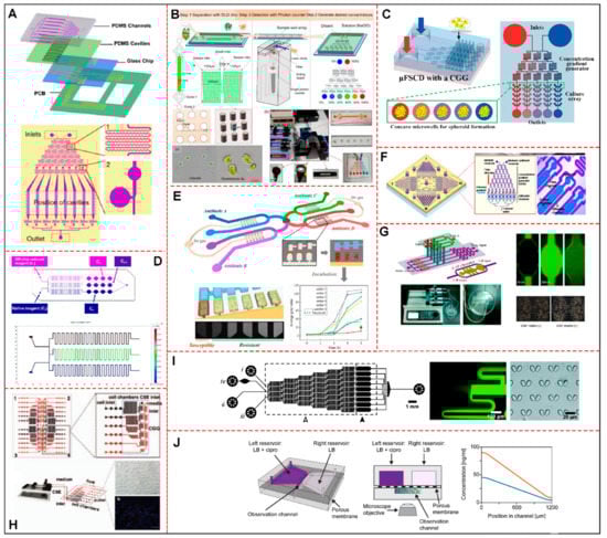
Figure 2.
Schematic diagram of microfluidic devices with CGG system for toxicological analysis, representing some of the studies selected in this systematic review. (A) Representation of device layers, gradient generator structure, details of fluid mixing units and air bubble valves. Adapted with permission from [44], Biosensors and Bioelectronics. (B) Project showing a physical map of the CGG system and the photomicrograph of Pyramimonas sp. and Chlorella. Adapted with permission from [23], Sensors (Switzerland). (C) A schematic showing the design of a μFSCD with a concentration gradient generator. It exposed the structures, dimensions, and characteristics of the two layers, adapted with permission from [34], Molecules. (D) Construction of the Sphero Chip system proving the measurement principle of the experimental scheme and results of the computational modeling of a CGG structure. Adapted with permission from [41], Lab on a Chip. (E) The microdevice contains eight sets of C-Chambers, which can simultaneously enable eight sets of noninterfering ASTs with each other. Antibiotics can be preincorporated into the C chambers with a specific mass gradient. AST and MIC results can be obtained by comparing the fluorescence intensities between each set of C-Chambers. Adapted with permission from [16], Biosensors and Bioelectronics. (F) CGG microdevice used for toxicity tests based on marine phytoplankton motility containing four units connected to a central removable outlet. Shown is the enlarged image of the single-frame unit containing an upstream CGG and downstream diffusible cameras. Motility signals can be collected in real time. Adapted with permission from [25], Marine Pollution Bulletin. (G) Schematic design of the CGG microfluidic chip with cell chambers (top panel) and the chip manufactured with pumping machine (bottom panel). Chamber-diffused Rh-123 (green) and morphological characteristics of A549 cells with or without CAF matrix are shown. Adapted with permission from [37], PLoS ONE. (H) CGG containing four parallel operational modules including inputs CSE: 18 parallel cell chambers and 6 cell inputs. A CSE concentration gradient is shown from entry one to six, adapted with permission from [40], Journal of Thoracic Oncology. (I) Schematic overview of the microfluidic device with a CGG and chambers with passive hydrodynamic cell trap arrays. It shows details of branching and diffusional mixing of two fluorescent fluids with different concentrations and optical micrograph of cell traps in PDMS. Adapted with permission from [42], Lab on a Chip. (J) Schematic drawing of the CGG device, illustrating cross-section and theoretical profiles of Ciprofloxacin concentration in the observation channel. Antibiotic solutions with 3× MIC (blue curve) or 6× MIC (orange curve). Adapted with permission from [17], Frontiers in Microbiology. Abbreviations: CGG: concentration gradient generator; μFSCD: microfluidic spheroid culture device; ASTs: antibiotic susceptibility tests; Rh−123: Rhodamine; A549: adenocarcinoma human alveolar basal epithelial cell line; CAF: cancer-associated fibroblasts; CSE: cigarette smoke extracts; PDMS: polydimethylsiloxane; MIC: minimal inhibitory concentration.
3.3. Concentration Gradient Generator Characteristics of Microfluidic Device
For the development of microfluidic devices capable of generating concentration gradients, it is necessary to establish general and functional characteristics, such as, as analyzed in Table 2, the methods and types of systems used to generate gradients, number of concentrations generated, linearity of the gradient, variation in concentrations of the compounds evaluated, and time to achieve gradient stability, as well as the duration of stability, in addition to information on simulation methods, validation, and advantages. Most studies used the Christmas tree gradient generation system (Figure 2A–D,F,G,I) [21,22,23,24,25,26,27,29,30,34,35,36,37,38,39,42,43,44,45,46,47,48], which uses the convective method, either associated or not associated with other systems or with certain modifications. Less frequently, other systems also used convective methods, such as T-shaped channels (6%) (Figure 2G) [20,37], serpentine channels (Figure 2A–D,F–I) [23,25,34,37,40,41,42,44] cascade mixing (Figure 2H) [40], and 3D microchannel networks [18] (3% each). Diffusion methods used to generate gradients were associated with Y-junction systems (6%) [21,28], the snake model [24], droplet generation (Figure 2E) [16], static-pressure-driven CGG [31], and membrane systems (Figure 2J) [17], with 3% each.
Table 2.
Concentration gradient generator characteristics of microfluidic device.
Interestingly, two of the studies, one from the microorganisms group and another from the tumor cells group, used a combination of convective and diffusive methods, such as serpentine/T-shaped channels [20], and Christmas tree/Y junction (Figure 2G) [37]. Only three studies did not report the generation method used, and the systems used were centrifugal CGG [19] and circular concentration gradient [33], while the study by Qin, Y.X. et al. reported neither the method nor the system [32]. The CGG structure was designed according to the gradient system used and the generation method, to ensure efficiency in toxicity screening. These important aspects of the CGG structure are highlighted in Table 2.
An alternative way to evaluate the functionality of the structures and the efficiency of the generation of gradients is the use of software to simulate the flow. In this review, only 18% of studies used COMSOL (software for multiphysics simulation) [17,18,28,30,31,41], mainly those on tumor cells and other models and microorganisms. The study by Han, B. et al. (microalgae group) performed the simulation through computational fluid dynamics (CFD) [24]. In the studies with embryos, simulation was not reported [47,48].
The devices developed in the selected studies generated from 2 to 65 different concentrations, with the greatest variation observed in the tumor cells and other models group, at 3 to 65 concentrations generated, and the lowest in the microalgae group, at 5 to 8 concentrations, with the microorganism and the zebrafish embryo groups having produced from 5 to 8 and 2 to 24 concentrations, respectively. The generated concentration values were reported in 91% of the studies, and they were considered linear [16,17,19,20,21,22,23,24,25,26,27,28,29,30,31,34,35,36,37,38,39,40,41,42,43,44,45,46,47,48].
For the creation of the perfect gradient, a certain amount of time is required, and only 30% of the studies reported these data, varying from 1 to 1800 s [16,26,27,28,36,37,41,42,45,48]. The stability time, also an important parameter, was reported in only 12% of studies [25,26,27], varying between 20 and 50 min in the microalgae group, with one study from the tumor cells and others group reporting an indefinite time of maintenance [28], while the other groups did not report this parameter.
One of the final steps in the development of the devices, validation, which aims to ensure the correct functioning of the gradient generator system, was reported in 55% of studies, with the main method used for this purpose being fluorescent agents [18,20,21,22,25,26,27,28,31,33,34,35,37,38,42,43,45,47], followed by food coloring, used in 12% of studies, one from the microorganism group [19] and three from the cells group [29,36,40]. Only one study (3%) used Doxorubicin (DOX) for validation [30]; the other 30% did not report this step [16,17,23,24,32,40,41,44,48].
Regarding the concentrations of drugs or stimuli used in the study of toxicity, some of the more frequently used substances showed a similar pattern. For the antibiotic toxicity screening in microorganisms, the most frequently used antibiotics were Ampicillin (AMP) and Tetracycline (TAC), with concentrations ranging from 0 to 13.1 μg/mL [16,18,19], while the concentration of Ciprofloxacin (CIPRO) ranged from 0 to 96 μg/mL [17]. For the evaluation of the toxicity in microalgae, the range of concentrations of copper (II) sulfate varied from 0 to 4.375 μM, and for mercury (II) chloride, from 0 to 4 μM [24,25]. The concentration variation in the main chemotherapies applied in toxicity screening in the tumor cells group varied from 0 to 600 mg/mL for 5-Fluorouracil (5-FU) [41,43,45,46], from 0 to 400 mg/mL for Cisplatin (CDDP) [29,35,45], 0 to 3.4 mg/mL for Paclitaxel (PTX) [35,37], and from 0 to 0.01825 mg/mL for DOX [30,36]. For studies related to embryogenesis, a lower range was used (0–100 μg/mL) for Adriamycin (ADM), DOX, 5-FU, and CDDP [48].
Some advantages regarding the CGG system and microdevice structure were reported in 55% of the studies. Shear-free fluid flow was a concern considered by 32% of the works, where shear minimization was provided, mainly, by the shape of the mixing channels, difference in heights in relation to the culture chamber, and use of splitting–mixing systems associated with serpentine channels [18,19,28,30,36,38]. Automation was also considered by 26% of the studies, so vacuum pressure channels (Figure 2A), centrifugal force [19], snake-channel torque-operated valves [26], and centripetal geometry [47] were used to minimize handling and optimize the generation of gradients [19,24,26,44,47]. To guarantee the linearity of the gradients, 21% of the studies reported the optimization of the structures by modifying the length of the channels (Figure 2A,H) [40,44], using micropillars in the culture chambers [30], radial splitting–mixing integration with a serpentine channel [33,45], and cascaded mixing (Figure 2H) [23,30,33,40]. In addition, 11% reported a concern regarding the high performance of these devices, the number of concentrations generated using radial splitting–mixing integration with a serpentine channel, and centripetal geometry together with the arrangement of concentric serpentine channels [45,47]. Only 5% of the studies reported a concern with mimicking the gradient in vivo [28] and reusing the developed devices [43].
3.4. Biological Model Used for Toxicity Evaluation in the CGG Microfluidic Device
Table 3 shows the details of the biological model used, the characteristics of the culture environment, and the toxicity conditions analyzed. The main microorganisms used as biological models were, firstly, bacteria (71.4%), with the great majority of the studies choosing different E. coli strains [16,17,18,19]—with exception of the study by DiCicco [21], in which a canine bacteria species (S. pseudintermedius) was used—and, secondly, Caenorhabditis elegans (C. elegans) nematode (28.6%) [20,22]. Both models were utilized for antibiotic toxicity screening—with exception of the study by Zhang B [20], which employed manganese chloride combined with vitamin E, resveratrol, and other substances. The most tested antibiotics were AMP [16,19], CIPRO [17,18], and TAC [16,18], followed by Kanamycin (KAN) [16], Amikacin (AMK) [18], Fosfomycin (FO) [21], and Amoxicillin (AMX) [22], with an incubation time between 4 and 72 h. The longer periods of incubation were associated with the evaluation of genetic mutation and antibiotic resistance. The drugs’ flow rates were reported in less than half of the studies (42.9%) [20,21,22], with a range of 10 to 300 μL/h, and the organisms were mostly cultured intra-CGG (85.7%) [16,17,19,20,21,22] and in 2D culture, with only two studies reporting the use of 3D culture (28.6%) [16,17], one being a co-culture. The average number of organisms for the studies that used bacteria was around 106 cfu/mL (108 for canine bacterium) and, for those based on nematodes, 1 worm/mL. Regarding the culture environment, the principal medium employed for bacteria culture was Luria–Bertani broth (for the E. coli strains), excluding the study based on S. pseudintermedius, which used Columbia agar associated with Tryptic soy broth plus glucose, and for C. elegans, a nematode growth medium was chosen. All bacteria were incubated with temperatures ranging from 30 to 37 °C, and the nematode studies applied lower temperatures around 20 to 25 °C.
Table 3.
Biological model used for toxicity evaluation in CGG microfluidic device.
Among the marine microalgae studied, 80% were Chlorophyta (green microalgae) [23,24,25,26,27], the most frequently seen species being P. subcordilformis (33.3%) [24,25,26,27], P. Helgolandica var. tsingtaoensis (25%) [25,26,27], and Chlorella sp. (16.7%) [23,26], all of which are from the previously cited phylum. This model was utilized for evaluating the toxicity of water pollutants, mainly metals and composts, most frequently copper (80%) [24,25,26,27], followed by mercury [24,25], cadmium [24,27], lead [25], and zinc [24], as well as other substances, such as sodium hypochlorite [23] and phenol [27]. The flow rates of the pollutant solutions and the exposure times in the toxicity evaluations varied greatly, from 0.1 to 50 μL/min and 1 to 72 h, respectively. These toxicity assays were mainly conducted intra-CGG (80%) [23,24,25,27], in an F/2 medium (80%) [24,25,26,27] (an enriched seawater medium was used in one study [23]), in a 2D arrangement, with an average amount of microalgae of 105 individuals or a range between 240 and 580 cells/μL, maintained mainly at 25 °C and in controlled light illumination of 60 μmol photon/m2/s.
Most of the selected studies used human cells (87.1%) [29,30,32,34,35,36,37,38,39,41,43,44,45,46] as the biological model for chemotherapy toxicity screening, consisting, basically, of different types of carcinoma (77.8%) [30,34,35,36,37,38,39,41,43,44,45,46], with the exception of kidney [29], endothelial [35], bronchial epithelial [32], and fibroblast cells [37], which were not necessarily used for the testing of anticancer drugs. Five studies opted for the use of cells from other organisms, such as embryonic stem cells from mice (9.7%) [28,31,43], insulinoma cells from rats (3.2%) [33], and saccharomyces yeast cells (3.2%) [42]. The employed test substances were, mostly, anticancer drugs, comprising 5-FU (26.3%) [35,41,43,45,46], CDDP (21.1%) [29,35,44,45], PTX (15.8%) [35,37,39], DOX (10.5%) [30,36], and, in lower frequency, Rapamycin [28], Gentamycin (GM) [29], Cyclosporin (CsA) [29], Cimetidine (Cim) [29], Irinotecan [34], Acetaminophen (APAP) [38], Pyocyanin (PCN) [39], and Cyclo-phosphamide (CP) [45], used at a percentage of 5.3% each, with the exception of cigarette smoke extract (10.5%) [32,39], hydrogen peroxide [31], glucose associated with glipizide [33], ascorbic acid [42], the combination of galactose, raffinose, and iron (III) chloride [42], and Celecoxib [43] (5.3% each), and their flow rates (average of 3.4 μL/min) and time of exposure (from 2 to 168 h) were extremely varied. Only 10.5% of the selected studies cultured the cells’ extra CGG system (Figure 2C) [34,35], that is, in a different layer from the one used for the generation of gradient concentrations or outside microfluidic devices, and the majority applied 2D culture (52.6%) (Figure 2A,I) [31,32,38,39,42,43,44,45,46], followed by 3D co-culture (15.8%) (Figure 2G) [29,30,37], spheroids (10.5%) (Figure 2C,D) [34,41], 3D culture (10.5%) [33,36], both 2D culture and spheroids (5.3%) [35], and both 2D and 3D cultures (5.3%) [28], using from 104 to 2.5 × 10⁷ cells/mL dispersed mainly in Dulbecco’s modified Eagle medium (DMEM) and its variations (42.1%) [29,30,31,35,36,38,44,45], followed by Roswell Park Memorial Institute (RPMI-1640) medium [32,33,37,41,44,46], and Eagle’s minimum essential medium (EMEM) [39,41]. All cells were incubated at 37 °C (aside from Saccharomyces [42], which were cultured at 30 °C), with a 5% CO2 humidified atmosphere.
Only two studies used the zebrafish embryos as the biological model [47,48], culturing them in 2D arrangement and intra-CGG, but with different purposes. One of the studies [47], which was performed with 10 to 12 eggs per chamber, focused on lead acetate and copper sulfate toxicity screening by exposing the embryos to these pollutants for 48 h, using flow rates from 5 to 30 μL/min and incubating them in an aerated ultrapure water medium supplemented with nitric acid and sodium hydroxide at 28.5 °C. The second study [48] was performed with one embryo/chamber for chemotherapy toxicity assessment, the drugs employed being ADM, DOX, 5-FU, and CDDP, as well as vitamin C, in different stages of embryo development (4 to 72 h post-fertilization), with the flow rate of 4 μL/min, with incubation in an E3 embryo medium at 26 °C, alternating between anoxia and normoxia.
3.5. Toxicity Screening Evaluation and Outcome of the CGG Microfluidic Device
Table 4 highlights the main points of the proposal, evaluation, and outcome of the selected studies. The main proposal of studies on the microfluidic devices that used microorganisms (bacteria and nematodes) as a model was to perform an AST with single or combined (due to the antagonism or synergism effect) drugs with different exposure times, using the MIC value as a reference to compare the results with the gold-standard method, searching for the best efficiency while using the lowest amount of drug possible, as assessed by cell viability fluorescent techniques, as well as the influence of the drug’s concentration on genetic alterations and mutations that lead to drug resistance, an extremely relevant issue nowadays due to widespread misusage of antibiotics. The nematodes were used for different purposes; one study [20] evaluated the behavioral response of the worms by fluorescence imaging in the face of manganese toxicity and the protective effect of natural antioxidants while the other [22] evaluated the effectiveness of certain antibiotics on the treatment of bacterial infection on nematodes, either associated or not associated with natural substances, showing these to be of value when treating the infection.
Table 4.
The proposal, evaluation, and outcome of the CGG microfluidic device studies applied in toxicity screening.
For marine microalgae, the main concern was the toxicity of chemicals linked to environmental contamination, either individually or in combination. These compounds were assessed using viability and motility techniques, which revealed varying sensitivities between different phytoplankton species. One study [23] concluded that Chrorella is more resistant than Pyraminmonas sp. to NaClO and the other microalgae, indicating the greater resistance of P. subcordiformis and P. helgolandica var. tsingtoaensis to all metals tested, especially CuSO4, which was shown to be the most toxic.
Most studies that proposed the screening of antitumor substances in cells from humans and animals assessed its efficiency via the use of different fluorescent dyes associated with cell viability evaluation (Calcein AM/Pi, Hoechst 33342, and Annexin-V-FITC), concluding that the drugs have a time/dose-dependent effect in almost all cases in which a drug was tested singly, and, also that the combination of drugs had better efficacy in lower dosages, with similar results seen for assays performed on Petri dish cultures. Only a few studies [28,29] assessed the effects of chemotherapy (or, in two studies [32,40], cigarette smoke extract) on normal cells, through the evaluation of apoptosis or oxidative stress via a reactive oxygen species (ROS) assay, showing that the toxicity and the malignant transformation of cells depend on the time of exposure. The study by Fernandes [42] was the exception in these approaches, evaluating the α-synuclein (aSyn) production and aggregation in Saccharomyces cerevisiae exposed to iron and ascorbic acid, due to the supposed protective effect of these substances.
Each of the zebrafish embryo investigations had a different objective. By using morphometric and behavioral analysis, one study [47] showed the damage effects of metal in different stages of embryo development. The second study [48] focused on the effects of chemotherapeutics normally used in embryo development and the ability of vitamin C to reduce harm.
As for the advantages of utilizing microfluidic devices rather than traditional macroscale methods, the great majority of the studies reported similar benefits. Firstly, some of the studies reported that the results obtained with microdevices correlate very well with those obtained using conventional methods, sometimes even mimicking more accurately in vivo conditions, showing that the technology in question can be adequately applied when studying toxicity. With that in mind, one of the most important aspects reported is the possibility provided by microfluidic CGG’s ability to generate a very sizeable number of different concentrations (up to 65 in the studies analyzed) in a single device and, consequently, the possibility of conducting multiple parallel assays, both of which, allied with the prospect of automation of processes (such as the generation of the concentration gradient and metabolite collection), can significantly diminish the time expended and make this a high throughput method for toxicity screening. Other very significant advantages brought about by this technology include the small size of the devices, which translates to less space occupied, making it possible to have multiple devices running multiple assays at the same time, further increasing the throughput, and also, the low quantity of reagents used, decreasing the cost of the tests. Besides that, the microdevices can be easily and rapidly fabricated, with different well-established fabrication processes and a variety of materials, and easily operated, as well as integrated with other traditional techniques, combining the advantages of both. Microdevices are also more preferable for 3D cultures than some of the more traditional methods, and they make it possible to create microenvironments that are more like those seen in nature, producing results that are more trustworthy. The analysis of microfluidic devices can also be carried out via a variety of methods, providing the researcher with a lot of design flexibility. The device’s versatility, which allows it to be developed in an endless number of ways for various purposes, with various test chemicals and biological models in mind, is still another significant advantage that can be seen. All these parameters are described in Table 4.
According to their toxicity methodologies and the biological models employed for this testing, the studies’ findings are described in Figure 3 in conjunction with the major features that are considered in this systematic review.
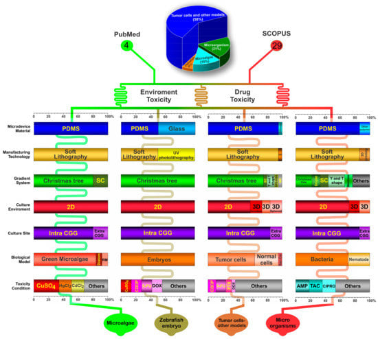
Figure 3.
The systematic review identified 4 main types of organisms used for toxicity analysis using the CGG system in microfluidic devices: microalgae, zebrafish embryo, tumor cells and other models, and microorganisms. The figure shows the main important aspects (as percentages) regarding the microfluidic device material, manufacturing technology, gradient system, culture environment, culture site, biological model, and toxicity condition. Abbreviations: PDMS: polydimethylsiloxane; SC: serpentine channel; CGG: concentration gradient generator; RM: red microalgae; CDDP: Cisplatin; 5-FU: 5-Fluorouracil; DOX: Doxorubicin; SM: silicon; SPD-CGG: static-pressure-driven CGG; NR: not reported; Sac-Cer: Saccharomyces cerevisiae; PTX: Paclitaxel; AMP: Ampicillin; TAC: Tetracycline; CIPRO: Ciprofloxacin.
4. Discussion
Advances in microfluidic device development technology for toxicity screening have provided remarkable advantages over conventional two-dimensional cultures due to the reduction in the sample consumption, reaction time, and cost of the operation. This systematic review gave a broad overview of the main aspects and trends regarding the manufacture of microfluidic devices, the promotion of the CGG’s development to boost the effectiveness of its chemical and drug toxicity screening, and the most tried-and-true biological models for addressing issues concerning environment and medical treatments.
Regarding microfluidic device fabrication, all were manufactured in-house, providing device customization for more efficient testing, which was specific to each biological model used. There is still a strong tendency to use materials and manufacturing techniques such as PDMS and soft lithography (91%), but recent articles search for more sophisticated technology, such as a 3D printing, silicon micromachining, and direct writing photolithography using glass. PDMS is the most commonly used material in microfluidics, because of its flexibility, biocompatibility, nontoxicity, good stability, and high transparency [49], even though earlier studies—some from more than a decade ago—brought up disadvantages, such as the absorption of small molecules [50], its incompatibility with organic solvents [51], and its vapor permeability [52], and more recent articles have questioned its practicality and widespread use, citing the difficulty of translating results obtained with it to other materials and its poor scalability for commercial purposes [53,54,55,56] as major concerns. The studies that did not use PDMS reported the use of materials such as silicon and glass which have, roughly, the same advantages as PDMS beside hydrophilic capabilities, reusability, and flexibility [45]. The biomedical field finds 3D printing to be a highly valuable technology for diagnostic and/or therapeutic purposes; its applications range from tissue engineering to microscale robotics and biosensors, besides rapid prototyping flexibility and a variety of forms and functions, having the advantages of precisely controlling the spatial distribution layer-by-layer, the generation of heterogeneous microorgans, and 3D cellular arrangement on a chip [57,58]. Only one study [39] utilized thermoplastics in some way, which is an interesting finding, given that, in recent years, materials such as polycarbonate (PC), poly (methyl methacrylate) (PMMA), and cyclic olefin copolymer (COC) have been gaining notoriety and have been widely used in industry when aiming for the fabrication of a product [53,54]
The studies that used conventional manufacturing varied the type and number of molds. Photolithography was the most used method of fabrication (79%), mostly due to its high accuracy, despite its high cost [59]. A study on optimization of SU-8 microstructure in high-transparency masks, printed in a photomask, however, showed the possibility of their fabrication with a low-cost process and without the requirement of cleanroom facilities [60]. Laser cutting techniques, as well as CNC, when compared to traditional photolithography and etching methods, have the advantages of being a simple, fast, and direct-write process for the fabrication of different geometrical shapes. Both techniques provide complex geometries with different layers, normally more than one layer (72.3%), with a micrometer scale. The layers represented the different environments and testing functions of the microdevice, providing greater efficiency within its complexity.
Most studies (73%) reported the use of new technologies, aiming to minimize microfluidic problems and also to innovate in the material and manufacturing of microdevices [16,17,18,19,20,21,22,23,24,27,28,29,31,32,34,35,36,37,38,41,42,44,47,48]. In addition, some studies proposed technological advances integrating electronic systems (9%) [19,20,31]. The evolution in the fabrication of complex and adaptive microfluidic devices was evidenced in the selected studies with implementations that showed significant advantages of the CGG used, such as its ability to create sophisticated and precisely defined gradient profiles.
The CGG system is a faster and more accurate method for drug and chemical pollutant toxicity analysis. It only needs a small amount of reagent for multiplex analysis, which lowers the cost. It is also capable of screening at the molecular and cellular levels and has multistep liquid-handling capabilities, which is especially useful for complicated screening procedures, in addition to its features of miniaturization, integration, and automation of analytical systems [36,61].
The method of gradient generation was based on two patterns, convective and diffusive. Most of the selected studies used the convective method for gradient generation (67%), which is a simpler and easier method for drawing and calculating. In convection-based gradient generators, the concentration gradient depends on the flow field, which can produce shear stress above the physiological limit endured by cells. The diffusion-based gradient generator, on the other hand, offers isolated chambers due to the interface, and the inside reagents are protected from the outside shearing [10]. The Christmas tree generation system was the most used (61%), associated and not associated with other systems, which indicates the frequency of the convective pattern, and its main advantages were its simple design and a well-defined concentration range, allowing isolated assessment of each concentration. However, this pattern can be integrated with other systems such as Y-junction systems or in two separate layers, one in which the convection pattern is evident (the CGG layer), forming the concentrations, and one containing the culture chamber, in which the different concentrations flow through diffusion. A few studies used similar systems to the Christmas tree, such as serpentine channels, cascading mixing, and T-shaped systems, which have certain advantages, for instance, fewer stages [62]. The studies that used the diffusion pattern applied a variety of gradient systems, such as Y-junction, membrane, and droplet generation. This last system shows difficulty in controlling flow and concentration while maintaining the droplet shape, two crucial parameters for toxicity assessment.
Gradient linearity is the expected behavior of CGG, being reported in 91% of studies due to the need to assess dose dependency on drugs and toxicity. The studies used two methods to analyze CGG linearity and performance: flow simulation and validation. The flow simulation occurs in a stage before the CGG manufacturing, allowing quick design adjustment, but only seven studies (21%) reported analysis using the COMSOL software, likely due to its high cost and requirement of an expert user, making access to it difficult. CGG validation is a different type of analysis that can only be performed once the microdevice is complete. The most employed substances for this method were fluorescent agents (55%) [18,20,21,22,25,26,27,28,31,34,35,37,38,42,43,45,47] followed by dye solutions (12%), bringing a visual analysis of the flows of the channels and the concentrations generated [19,29,36,38,39]. Some studies also performed a quantitative analysis to be compared with the final concentrations.
Considering the publication year of the 33 studies included in this systematic review and the different approaches for toxicity screening, the studies from the first five years directed greater attention to environmental problems, such as contamination of the seas by metals and other pollutants (60%) [25,26,27,35] and advances in treatment with chemotherapeutics, seeking better drug combinations for better efficiency (63%) [35,36,37,38,39,40,41,42,43,44,45,46], both contexts being analyzed in studies using zebrafish embryos [47,48]. Currently, studies are more focused on effective antitumor therapies (37%) [28,29,30,31,32,33,34] and pollutants’ toxicity in the marine microenvironment (40%) [23,24], while the concern over antimicrobial treatments has grown (43% [20,21,22] to 57% [16,17,18,19]).
Among the most tested antibiotics in the toxicity analysis, there was a slight predominance of Ampicillin and Ciprofloxacin, which are effective against a wide range of both Gram-positive and Gram-negative bacteria, while having distinct modes of action [63]. The concentration range of both drugs showed a similar pattern (from 2 to 16), showing MIC values consistent with the gold standard of conventional analysis, being more efficient in terms of analysis time and material consumption, and allowing combined-drug analysis for synergism and antagonism effects, using a drug exposure time from 4 to 72 h. The use of prolonged subtherapeutic levels is a concern regarding bacterial resistance, with microfluidic devices having been shown to be more efficient for this analysis than conventional techniques due to the possibility of mimicking the in vivo microenvironment, while guaranteeing high performance [64]. The main bacteria utilized as a model was the Gram-negative Escherichia coli (E. Coli) (for example, E. Coli k-12), which may cause severe food poisoning and is a global health problem due to the rise in antibiotic resistance. Due to its unrivaled fast growth kinetics, high-cell-density cultures, and quick and simple exogenous DNA transformation, this species of bacteria is the most popular for use in toxicity assays [65]. Almost all bacteria were cultured inside the CGG system in a 2D culture dispersed in a medium from 30 to 37 °C, with the exception of the study by Sweet [18], which cultured them in a separate system (extra CGG), and the studies by Zeng [16], which used 3D culture, and Nagy, who used 3D co-culture [17].
A few studies also used nematode C. elegans as a model for toxicity screening, assessing the influence of antibacterial activity with various rhubarb components [22], and dopaminergic neurotoxicity induced or not by manganese associated with antioxidant elements [20]. This is a strong model organism because of its small size, optical transparency, short life cycle, and genetic tractability, among other advantageous traits, such as the ability to be infected by a variety of human pathogens and low cost of maintenance [66]. This microorganism was also cultured inside the CGG system in 2D culture dispersed in the medium from 20 to 25 °C.
Through the evaluation of metals and contaminants, a number of research articles have addressed the problem of environmental toxicity. Global pollutants such as mercury and lead, for instance, have an impact on both human health and the ecology around the world [67]. Microalgae have reportedly been used for biological detoxification, effluent treatment, control of toxic metals in natural waters or effluents, and control of toxic metals in naturally or industrially contaminated waters [68], as well as to retain and immobilize some compounds. Thus, it is essential to create tools that can investigate and aid in the creation of new technologies that are beneficial for the environment and, by extension, for human health and quality of life. Although other metals, such as arsenic (As), cadmium (Cd), chromium (Cr), lead (Pb), and mercury (Hg), are poisonous to microalgae, they can ingest trace amounts of metals, including boron (B), cobalt (Co), copper (Cu), iron (Fe), molybdenum (Mo), manganese (Mn), and zinc (Zn). Low-hazardous metal and compost concentrations can promote the growth and metabolism of microalgae because of the hormesis phenomena [69].
The metals Cu [24,25,26,27], Cd [24,27], and Hg [20,24] were evaluated the most often, singly or combined with other chemical elements, likely due to the high plastic accumulation in oceans from unrecycled waste and its decomposition [70] or the increase in mining and industrial activity, leading to mercury deposit [70]. The concentration range of these metals was similar (from 0 to 4 µM), varying from five to eight different concentrations tested. Green microalgae (Chlorophyta), the main model used, are photosynthetic protists and one of the groups of algae most closely related to terrestrial plants, also being used as indicators of water quality and having significant ecological importance, as they are components of phytoplankton, one of the primary producers in the food chain [71]. The microalgae were cultured mainly inside the CGG system—with the exception of the study by Zheng [26], which cultured them outside the CGG system—in 2D culture dispersed in the F/2 medium at about 25 °C, in controlled light illumination of 60 μmol photon/m2/s, close to normal environmental conditions.
Zebrafish embryos are frequently used in metal toxicity studies due to their ability to grow outward and having clear enough bodies to be examined under a standard optical microscope [72]. One study in this review evaluated the Pb and Cu toxicity, singly and combined, regarding its teratogenicity in different stages of embryo development, such as the larval, juvenile, and adult stages [47]. Another study used this model to analyze different types of chemotherapy drugs and the protective effect of vitamin C during treatment, evaluating their influence according to the developmental embryo stages [48], using drug doses significantly lower than those applied in the tumor cell and other models group. These embryos were cultured inside the CGG system in 2D culture dispersed in different medium conditions at about 27 °C, and the toxicity evaluation occurred from 1 to 72 h of exposure.
The vast majority of the tumor cell and other model group studies performed antitumor toxicity screening using various tumor cell types from human [26,30,31,32,33,34,35,36,37,39,40,41,42] or animals [33] and normal human cells [29,32,35], evaluating, primarily, the effect of the drugs 5-FU [35,41,43,45,46], CDDP [29,35,44,45], PTX [35,37,39], DOX [30,36], isolated or combined with others. CDDP and 5-FU combined are considered the standard antitumor treatment, and PTX followed by CDDP showed greater antitumor activity [73]. The toxicity of isolated Doxorubicin occur via acting on DNA by slowing or stopping the proliferation of cancer cells by inhibiting an enzyme called topoisomerase 2, their cardiotoxicity is the main factor restricting its use, and the total cumulative dose is the only factor currently utilized to predict toxicity, with microfluidics providing a new form of assessment [74]. 5-FU and CDDP also have activity on DNA, inhibiting thymidylate synthase, and crosslinking with the urine bases on the DNA to form DNA adducts, preventing repair of the DNA, leading to DNA damage and subsequently inducing apoptosis within cancer cells, respectively. The dose of these drugs was significant compared to other drugs, ranging from 0 to 600 mg/mL for 5-FU and 0 to 400 mg/mL for CDDP. PTX has a different antitumor mechanism, promoting the assembly of tubulin into microtubules and preventing the dissociation of microtubules, blocking cell cycle progression, preventing mitosis, and inhibiting the growth of cancer cells, being used, in the studies, in lower doses, from 0 to 3.4 mg/mL [75].
These cells were mainly cultured inside the CGG system in 2D conventional culture dispersed in DMEM or RPMI media, being mostly supplemented with fetal bovine serum (FBS) and other supplements at 37 °C. A few studies also used 3D culture and co-culture with different tumor or normal cells, and some studies specified the use of spheroids, a variation of conventional 3D culture. 2D cell culture models have been used to assess the toxicity or efficacy of drug candidates due to the ability to anticipate drug responses, but they have been found to be comparatively weak in comparison to 3D cell cultures, which have better functional and phenotypic characteristics, as well as predictability of therapeutic effectiveness [34,35]. In vivo, cells are arranged spatially into three-dimensional (3D) patterns that are encircled by an extracellular matrix (ECM), which leads to cancer cells growing in 3D cultures; in comparison to 2D cultures, these cells are more resistant to cytotoxic drugs [76]. Spheroids are one of the most relevant and modern models for cancer research. Their morphology and physiology are similar to those of a tumor in vivo, showing a network of cell–cell interactions, a 3D structure, the presence of a natural extracellular matrix, and nutrients, metabolites, and oxygen gradients [77,78].
Other contexts also used normal cells without the influence of chemotherapeutics. Two studies evaluated the influence of dose and time of exposure to tobacco extract on the malignant transformation of normal bronchial cells. The tobacco epidemic is one of the biggest public health threats the world has ever faced; there is no safe level of exposure to tobacco, and chronic cigarette-smoke-induced time-dependent epigenetic alterations can sensitize human bronchial epithelial cells for transformation by a single oncogene [79]. The study by Fernandes [42] investigated the basic molecular effects of aSyn in the context of living cells, with human aSyn being expressed in yeast and found to induce dose-dependent cytotoxicity, while iron (III) chloride and ascorbic acid were shown to have a protective effect [42]. The molecular basis of various human diseases has been extensively researched using Saccharomyces cerevisiae as a model organism. It is most well-studied in eukaryotic cells, while also being the easiest organism to grow under controlled circumstances and to manipulate genetically [80]. The study by Luo [33] used the INS-1 cells, which are a widely used and well-established model for the study of diabetes and their property of glucose-stimulated insulin secretion [81].
A relevant aspect in studies with microfluidics devices evaluated in the biological model was the flow rate used to infuse the nutrients and components to be tested for toxicity. This condition is very important in the biological environment. In microfluidic devices, shear stress is created by fluid flow injection due to several important aspects, such as channel dimensions and geometry, cell concentration, cell line type, and the way the flow rate is delivered, among others. Microfluidics provides a good way to mimic flows found in veins and small arteries, where the flow is usually unidirectional and laminar [82]. Shear stress can influence cell attachment [83], pathological response [84], and developmental biology [85].
The studies’ outcomes in toxicity screening using the CGG system in the microfluidics device showed comparable results to the conventional toxicity studies, and the efficiency evaluation techniques applied were mainly based on fluorescence signals, followed by spectrophotometry and brightfield microscopy, molecular methods, and other techniques (enzyme-linked immunosorbent assay—ELISA, 3-[4,5-dimethylthiazol-2-yl]-2,5 diphenyl tetrazolium bromide—MTT, and Western blot), showing the achievement of high efficiency in a faster way and the possibility of automation.
One of the limitations of this review was the lack of a detailed comparison of the complexity of the structures and geometries presented by the microfluidic devices developed in the studies. This analysis could help us better understand the significance of the micro-CGG on a global scale as well as the role that device design plays in the generation of the gradient and in each biological model that was investigated, but it was challenging due to the wide variation in the geometric arrangement and size of the studied biological models. Another limitation was the time frame used, 10 years, it was not sufficient to confirm whether there was a trend of CGG devices in relation to manufacturing characteristics, and previous gradient generation systems.
This systematic review also identified some methodological problems and research gaps, such as the relationship between the material used to make devices and the biological model or substance tested for toxicity, taking into account the benefits and drawbacks of each material, the sparse use of simulation procedures prior to device fabrication, and also the methodological care with regard to the duration of stable concentrations obtained by the CGG, which may compromise the accuracy of toxicity evaluation.
5. Conclusions
This systematic review showed a variety of toxicity assessment applications in the environmental and medical approaches through concentration gradient generation systems in microfluidic devices. Current studies have adopted new technologies and complex structures to customize the device according to the biological model, to achieve the best testing efficiency and to minimize typical microfluidics issues such as bubbles and shearing. The microfluidic gold-standard technique, soft lithography, using the polymer PDMS, was still the most frequently used, and the Christmas tree shape was the most prevalent CGG design, but alternative techniques and designs were employed to produce a larger variety of concentrations and drug combinations more precisely and more outcomes at once. Thus, the CGG microdevice is an alternative to common pipetting techniques for the evaluation of drugs’/substances’ toxicity in various biological organisms, bringing greater precision with a lower cost.
Author Contributions
Conceptualization, N.M.E.V., M.P.N., A.H.A., L.D.R. and L.F.G.; methodology, N.M.E.V., M.P.N., A.H.A., L.D.R. and L.F.G.; validation, N.M.E.V., M.P.N., A.H.A., L.D.R., J.B.M., F.A.O., C.S.L. and L.F.G.; formal analysis, N.M.E.V., M.P.N., A.H.A., L.D.R., J.B.M., F.A.O., C.S.L., A.T.L., M.N.P.C. and L.F.G.; investigation, N.M.E.V., M.P.N., A.H.A., L.D.R., J.B.M., F.A.O., C.S.L., A.T.L., M.N.P.C. and L.F.G.; resources, N.M.E.V., M.P.N., A.H.A., L.D.R., J.B.M., F.A.O., C.S.L. and L.F.G.; data curation, N.M.E.V., M.P.N., A.H.A., L.D.R., J.B.M., F.A.O., C.S.L., A.T.L., M.N.P.C. and L.F.G.; writing—original draft preparation, N.M.E.V., M.P.N., A.H.A., L.D.R. and L.F.G.; writing—review and editing, N.M.E.V., M.P.N., A.H.A., L.D.R. and L.F.G.; visualization, N.M.E.V., M.P.N., A.H.A., L.D.R. and L.F.G.; supervision, L.F.G.; project administration, L.F.G.; funding acquisition, L.F.G. All authors have read and agreed to the published version of the manuscript.
Funding
Supported by CNPq, No. 308901/2020, No. 400856/2016-6; FAPESP, No. 2019/21070-3, No. 2017/17868-4, No. 2016/21470-3; SisNANO 2.0/MCTIC, No. 442539/2019-3; the National Institute of Science and Technology Complex Fluids (INCT-FCx); and PIPEq-AUXP-22004.
Institutional Review Board Statement
Not applicable.
Informed Consent Statement
Not applicable.
Data Availability Statement
Not applicable.
Acknowledgments
Not applicable.
Conflicts of Interest
The authors declare no conflict of interest.
References
- Erhirhie, E.O.; Ihekwereme, C.P.; Ilodigwe, E.E. Advances in acute toxicity testing: Strengths, weaknesses and regulatory acceptance. Interdiscip. Toxicol. 2018, 11, 5–12. [Google Scholar] [CrossRef]
- Chapman, K.L.; Holzgrefe, H.; Black, L.E.; Brown, M.; Chellman, G.; Copeman, C.; Couch, J.; Creton, S.; Gehen, S.; Hoberman, A.; et al. Pharmaceutical toxicology: Designing studies to reduce animal use, while maximizing human translation. Regul. Toxicol. Pharmacol. 2013, 66, 88–103. [Google Scholar] [CrossRef]
- Singh, S.; Khanna, V.K.; Pant, A.B. Chapter 1—Development of In Vitro Toxicology: A Historic Story. In In Vitro Toxicology; Dhawan, A., Kwon, S., Eds.; Academic Press: Cambridge, MA, USA, 2018; pp. 1–19. [Google Scholar]
- Saxena, S.; Joshi, R. Microfluidic Devices: Applications and Role of Surface Wettability in Its Fabrication; IntechOpen: London, UK, 2020. [Google Scholar]
- Gomez, F.A. The future of microfluidic point-of-care diagnostic devices. Bioanalysis 2012, 5, 1–3. [Google Scholar] [CrossRef]
- Nguyen, N.T.; Shaegh, S.A.; Kashaninejad, N.; Phan, D.T. Design, fabrication and characterization of drug delivery systems based on lab-on-a-chip technology. Adv. Drug Deliv. Rev. 2013, 65, 1403–1419. [Google Scholar] [CrossRef]
- Oliveira, A.F.; Pessoa, A.C.S.N.; Bastos, R.G.; de la Torre, L.G. Microfluidic tools toward industrial biotechnology. Biotechnol. Prog. 2016, 32, 1372–1389. [Google Scholar] [CrossRef]
- Nur, O.; Willander, M. Chapter 3—Conventional nanofabrication methods. In Low Temperature Chemical Nanofabrication; Nur, O., Willander, M., Eds.; William Andrew Publishing: Norwich, NY, USA, 2020; pp. 49–86. [Google Scholar]
- Burklund, A.; Tadimety, A.; Nie, Y.; Hao, N.; Zhang, J.X.J. Chapter One—Advances in diagnostic microfluidics. In Advances in Clinical Chemistry; Makowski, G.S., Ed.; Elsevier: Amsterdam, The Netherlands, 2020; Volume 95, pp. 1–72. [Google Scholar]
- Toh, A.G.G.; Wang, Z.P.; Yang, C.; Nguyen, N.-T. Engineering microfluidic concentration gradient generators for biological applications. Microfluid. Nanofluidics 2014, 16, 1–18. [Google Scholar] [CrossRef]
- Ortseifen, V.; Viefhues, M.; Wobbe, L.; Grünberger, A. Microfluidics for Biotechnology: Bridging Gaps to Foster Microfluidic Applications. Front. Bioeng. Biotechnol. 2020, 8, 589074. [Google Scholar] [CrossRef]
- Yu, F.; Hunziker, W.; Choudhury, D. Engineering Microfluidic Organoid-on-a-Chip Platforms. Micromachines 2019, 10, 165. [Google Scholar] [CrossRef]
- Petreus, T.; Cadogan, E.; Hughes, G.; Smith, A.; Pilla Reddy, V.; Lau, A.; O’Connor, M.J.; Critchlow, S.; Ashford, M.; O’Connor, L.O. Tumour-on-chip microfluidic platform for assessment of drug pharmacokinetics and treatment response. Commun. Biol. 2021, 4, 1001. [Google Scholar] [CrossRef]
- Kim, S.C.; Cestellos-Blanco, S.; Inoue, K.; Zare, R.N. Miniaturized Antimicrobial Susceptibility Test by Combining Concentration Gradient Generation and Rapid Cell Culturing. Antibiotics 2015, 4, 455–466. [Google Scholar] [CrossRef]
- Liberati, A.; Altman, D.G.; Tetzlaff, J.; Mulrow, C.; Gotzsche, P.C.; Ioannidis, J.P.; Clarke, M.; Devereaux, P.J.; Kleijnen, J.; Moher, D. The PRISMA statement for reporting systematic reviews and meta-analyses of studies that evaluate health care interventions: Explanation and elaboration. PLoS Med. 2009, 6, e1000100. [Google Scholar] [CrossRef] [PubMed]
- Zeng, W.; Chen, P.; Li, S.; Sha, Q.; Li, P.; Zeng, X.; Feng, X.; Du, W.; Liu, B.F. Hand-powered vacuum-driven microfluidic gradient generator for high-throughput antimicrobial susceptibility testing. Biosens. Bioelectron. 2022, 205, 114100. [Google Scholar] [CrossRef] [PubMed]
- Nagy, K.; Dukic, B.; Hodula, O.; Ábrahám, Á.; Csákvári, E.; Dér, L.; Wetherington, M.T.; Noorlag, J.; Keymer, J.E.; Galajda, P. Emergence of Resistant Escherichia coli Mutants in Microfluidic On-Chip Antibiotic Gradients. Front. Microbiol. 2022, 13, 820738. [Google Scholar] [CrossRef] [PubMed]
- Sweet, E.; Yang, B.; Chen, J.; Vickerman, R.; Lin, Y.; Long, A.; Jacobs, E.; Wu, T.; Mercier, C.; Jew, R.; et al. 3D microfluidic gradient generator for combination antimicrobial susceptibility testing. Microsyst. Nanoeng. 2020, 6, 92. [Google Scholar] [CrossRef] [PubMed]
- Tang, M.; Huang, X.; Chu, Q.; Ning, X.; Wang, Y.; Kong, S.K.; Zhang, X.; Wang, G.; Ho, H.P. A linear concentration gradient generator based on multi-layered centrifugal microfluidics and its application in antimicrobial susceptibility testing. Lab. Chip 2018, 18, 1452–1460. [Google Scholar] [CrossRef]
- Zhang, B.; Li, Y.; He, Q.; Qin, J.; Yu, Y.; Li, X.; Zhang, L.; Yao, M.; Liu, J.; Chen, Z. Microfluidic platform integrated with worm-counting setup for assessing manganese toxicity. Biomicrofluidics 2014, 8, 054110. [Google Scholar] [CrossRef]
- DiCicco, M.; Neethirajan, S. An in vitro microfluidic gradient generator platform for antimicrobial testing. Biochip J. 2014, 8, 282–288. [Google Scholar] [CrossRef]
- Yang, J.; Chen, Z.; Ching, P.; Shi, Q.; Li, X. An integrated microfluidic platform for evaluating in vivo antimicrobial activity of natural compounds using a whole-animal infection model. Lab. A Chip 2013, 13, 3373–3382. [Google Scholar] [CrossRef]
- Wang, Y.; Wang, J.; Zhou, C.; Ding, G.; Chen, M.; Zou, J.; Wang, G.; Kang, Y.; Pan, X. A microfluidic prototype system towards microalgae cell separation, treatment and viability characterization. Sensors 2019, 19, 4940. [Google Scholar] [CrossRef]
- Han, B.; Zheng, G.; Wei, J.; Yang, Y.; Lu, L.; Zhang, Q.; Wang, Y. Computer-aided design of microfluidic resistive network using circuit partition and CFD-based optimization and application in microalgae assessment for marine ecological toxicity. Bioprocess Biosyst. Eng. 2019, 42, 785–797. [Google Scholar] [CrossRef]
- Zheng, G.X.; Li, Y.J.; Qi, L.L.; Liu, X.M.; Wang, H.; Yu, S.P.; Wang, Y.H. Marine phytoplankton motility sensor integrated into a microfluidic chip for high-throughput pollutant toxicity assessment. Mar. Pollut. Bull. 2014, 84, 147–154. [Google Scholar] [CrossRef] [PubMed]
- Zheng, G.; Wang, Y.; Wang, Z.; Zhong, W.; Wang, H.; Li, Y. An integrated microfluidic device in marine microalgae culture for toxicity screening application. Mar. Pollut. Bull. 2013, 72, 231–243. [Google Scholar] [CrossRef] [PubMed]
- Zheng, G.; Wang, Y.; Qin, J. Microalgal motility measurement microfluidic chip for toxicity assessment of heavy metals. Anal. Bioanal. Chem. 2012, 404, 3061–3069. [Google Scholar] [CrossRef]
- Chennampally, P.; Sayed-Zahid, A.; Soundararajan, P.; Sharp, J.; Cox, G.A.; Collins, S.D.; Smith, R.L. A microfluidic approach to rescue ALS motor neuron degeneration using rapamycin. Sci. Rep. 2021, 11, 18168. [Google Scholar] [CrossRef]
- Yin, L.; Du, G.; Zhang, B.; Zhang, H.; Yin, R.; Zhang, W.; Yang, S.-M. Efficient Drug Screening and Nephrotoxicity Assessment on Co-culture Microfluidic Kidney Chip. Sci. Rep. 2020, 10, 6568. [Google Scholar] [CrossRef]
- Jaberi, A.; Monemian Esfahani, A.; Aghabaglou, F.; Park, J.S.; Ndao, S.; Tamayol, A.; Yang, R. Microfluidic Systems with Embedded Cell Culture Chambers for High-Throughput Biological Assays. ACS Appl. Bio Mater. 2020, 3, 6661–6671. [Google Scholar] [CrossRef] [PubMed]
- Zhao, X.; Yan, X.; Li, Y.; Liu, B.F. Static pressure-driven microfluidic gradient generator for long-term cell culture and adaptive cytoprotection analysis. Microfluid. Nanofluidics 2019, 23, 62. [Google Scholar] [CrossRef]
- Qin, Y.X.; Yang, Z.H.; Du, X.H.; Zhao, H.; Liu, Y.B.; Guo, Z.; Wang, Q. Inhibition of the hedgehog signaling pathway depresses the cigarette smoke-induced malignant transformation of 16HBE cells on a microfluidic chip. Chin. Med. J. 2018, 131, 1191–1198. [Google Scholar] [CrossRef]
- Luo, Y.; Zhang, X.; Li, Y.; Deng, J.; Li, X.; Qu, Y.; Lu, Y.; Liu, T.; Gao, Z.; Lin, B. High-glucose 3D INS-1 cell model combined with a microfluidic circular concentration gradient generator for high throughput screening of drugs against type 2 diabetes. RSC Adv. 2018, 8, 25409–25416. [Google Scholar] [CrossRef]
- Lim, W.; Park, S. A Microfluidic Spheroid Culture Device with a Concentration Gradient Generator for High-Throughput Screening of Drug Efficacy. Molecules 2018, 23, 3355. [Google Scholar] [CrossRef]
- Jin, D.; Ma, X.; Luo, Y.; Fang, S.; Xie, Z.; Li, X.; Qi, D.; Zhang, F.; Kong, J.; Li, J.; et al. Application of a microfluidic-based perivascular tumor model for testing drug sensitivity in head and neck cancers and toxicity in endothelium. RSC Adv. 2016, 6, 29598–29607. [Google Scholar] [CrossRef]
- Hong, B.; Xue, P.; Wu, Y.; Bao, J.; Chuah, Y.J.; Kang, Y. A concentration gradient generator on a paper-based microfluidic chip coupled with cell culture microarray for high-throughput drug screening. Biomed. Microdevices 2016, 18, 21. [Google Scholar] [CrossRef] [PubMed]
- Ying, L.; Zhu, Z.; Xu, Z.; He, T.; Li, E.; Guo, Z.; Liu, F.; Jiang, C.; Wang, Q. Cancer associated fibroblast-derived hepatocyte growth factor inhibits the paclitaxel-induced apoptosis of lung cancer A549 cells by up-regulating the PI3K/Akt and GRP78 signaling on a microfluidic platform. PLoS ONE 2015, 10, e0129593. [Google Scholar] [CrossRef] [PubMed]
- Ju, S.M.; Jang, H.J.; Kim, K.B.; Kim, J. High-Throughput Cytotoxicity Testing System of Acetaminophen Using a Microfluidic Device (MFD) in HepG2 Cells. J. Toxicol. Environ. Health Part A Curr. Issues 2015, 78, 1063–1072. [Google Scholar] [CrossRef] [PubMed]
- Pasirayi, G.; Scott, S.M.; Islam, M.; O’Hare, L.; Bateson, S.; Ali, Z. Low cost microfluidic cell culture array using normally closed valves for cytotoxicity assay. Talanta 2014, 129, 491–498. [Google Scholar] [CrossRef]
- Li, E.; Xu, Z.; Liu, F.; Wang, H.; Wen, J.; Shao, S.; Zhang, L.; Wang, L.; Liu, C.; Lu, J.; et al. Continual exposure to cigarette smoke extracts induces tumor-like transformation of human nontumor bronchial epithelial cells in a microfluidic chip. J. Thorac. Oncol. 2014, 9, 1091–1100. [Google Scholar] [CrossRef]
- Kwapiszewska, K.; Michalczuk, A.; Rybka, M.; Kwapiszewski, R.; Brzózka, Z. A microfluidic-based platform for tumour spheroid culture, monitoring and drug screening. Lab Chip 2014, 14, 2096–2104. [Google Scholar] [CrossRef]
- Fernandes, J.T.; Tenreiro, S.; Gameiro, A.; Chu, V.; Outeiro, T.F.; Conde, J.P. Modulation of alpha-synuclein toxicity in yeast using a novel microfluidic-based gradient generator. Lab Chip 2014, 14, 3949–3957. [Google Scholar] [CrossRef]
- Jastrzebska, E.; Flis, S.; Rakowska, A.; Chudy, M.; Jastrzebski, Z.; Dybko, A.; Brzozka, Z. A microfluidic system to study the cytotoxic effect of drugs: The combined effect of celecoxib and 5-fluorouracil on normal and cancer cells. Microchim. Acta 2013, 180, 895–901. [Google Scholar] [CrossRef]
- Xu, Y.; Lv, Y.; Wang, L.; Xing, W.; Cheng, J. A microfluidic device with passive air-bubble valves for real-time measurement of dose-dependent drug cytotoxicity through impedance sensing. Biosens. Bioelectron. 2012, 32, 300–304. [Google Scholar] [CrossRef]
- Yang, C.G.; Wu, Y.F.; Xu, Z.R.; Wang, J.H. A radial microfluidic concentration gradient generator with high-density channels for cell apoptosis assay. Lab A Chip 2011, 11, 3305–3312. [Google Scholar] [CrossRef] [PubMed]
- Jedrych, E.; Flis, S.; Sofinska, K.; Jastrzebski, Z.; Chudy, M.; Dybko, A.; Brzozka, Z. Evaluation of cytotoxic effect of 5-fluorouracil on human carcinoma cells in microfluidic system. Sens. Actuators B Chem. 2011, 160, 1544–1551. [Google Scholar] [CrossRef]
- Li, Y.; Yang, X.; Chen, Z.; Zhang, B.; Pan, J.; Li, X.; Yang, F.; Sun, D. Comparative toxicity of lead (Pb2+), copper (Cu2+), and mixtures of lead and copper to zebrafish embryos on a microfluidic chip. Biomicrofluidics 2015, 9, 024105. [Google Scholar] [CrossRef] [PubMed]
- Yang, F.; Chen, Z.; Pan, J.; Li, X.; Feng, J.; Yang, H. An integrated microfluidic array system for evaluating toxicity and teratogenicity of drugs on embryonic zebrafish developmental dynamics. Biomicrofluidics 2011, 5, 024115. [Google Scholar] [CrossRef]
- Lin, L.; Chung, C.K. PDMS Microfabrication and Design for Microfluidics and Sustainable Energy Application: Review. Micromachines 2021, 12, 1350. [Google Scholar] [CrossRef] [PubMed]
- Toepke, M.W.; Beebe, D.J. PDMS absorption of small molecules and consequences in microfluidic applications. Lab Chip 2006, 6, 1484–1486. [Google Scholar] [CrossRef] [PubMed]
- Sackmann, E.K.; Fulton, A.L.; Beebe, D.J. The present and future role of microfluidics in biomedical research. Nature 2014, 507, 181–189. [Google Scholar] [CrossRef]
- Mukhopadhyay, R. When PDMS isn’t the best. Anal. Chem. 2007, 79, 3248–3253. [Google Scholar] [CrossRef]
- Cong, H.; Zhang, N. Perspectives in translating microfluidic devices from laboratory prototyping into scale-up production. Biomicrofluidics 2022, 16, 021301. [Google Scholar] [CrossRef]
- Scott, S.; Ali, Z. Fabrication Methods for Microfluidic Devices: An Overview. Micromachines 2021, 12, 319. [Google Scholar] [CrossRef]
- Monjezi, M.; Rismanian, M.; Jamaati, H.; Kashaninejad, N. Anti-Cancer Drug Screening with Microfluidic Technology. Appl. Sci. 2021, 11, 9418. [Google Scholar] [CrossRef]
- Wang, Y.; Chen, S.; Sun, H.; Li, W.; Hu, C.; Ren, K. Recent progresses in microfabricating perfluorinated polymers (Teflons) and the associated new applications in microfluidics. Microphysiological Syst. 2018, 2, 1–11. [Google Scholar] [CrossRef]
- Hwang, H.; Zhu, W.; Victorine, G.; Lawrence, N.; Chen, S. 3D-Printing of Functional Biomedical Microdevices via Light- and Extrusion-Based Approaches. Small Methods 2017, 2, 1700277. [Google Scholar] [CrossRef] [PubMed]
- Carvalho, V.; Gonçalves, I.; Lage, T.; Rodrigues, R.O.; Minas, G.; Teixeira, S.F.C.F.; Moita, A.S.; Hori, T.; Kaji, H.; Lima, R.A. 3D Printing Techniques and Their Applications to Organ-on-a-Chip Platforms: A Systematic Review. Sensors 2021, 21, 3304. [Google Scholar] [CrossRef] [PubMed]
- Hazelton, A.J.; Wüest, A.; Hughes, G.; Litt, L.C.; Goodwin, F. Cost of ownership for future lithography technologies. In Proceedings of the SPIE Lithography Asia, Taipei, Taiwan, 4–6 November 2008. [Google Scholar]
- Pinto, V.V.C.; Sousa, P.; Cardoso, V.; Minas, G. Optimized SU-8 Processing for Low-Cost Microstructures Fabrication without Cleanroom Facilities. Micromachines 2014, 5, 738–755. [Google Scholar] [CrossRef]
- Du, G.S.; Pan, J.Z.; Zhao, S.P.; Zhu, Y.; den Toonder, J.M.; Fang, Q. Cell-based drug combination screening with a microfluidic droplet array system. Anal. Chem. 2013, 85, 6740–6747. [Google Scholar] [CrossRef] [PubMed]
- Wang, X.; Liu, Z.; Pang, Y. Concentration gradient generation methods based on microfluidic systems. RSC Adv. 2017, 7, 29966–29984. [Google Scholar] [CrossRef]
- Sharma, D.; Patel, R.P.; Zaidi, S.T.R.; Sarker, M.M.R.; Lean, Q.Y.; Ming, L.C. Interplay of the Quality of Ciprofloxacin and Antibiotic Resistance in Developing Countries. Front. Pharmacol. 2017, 8, 546. [Google Scholar] [CrossRef]
- Dal Sasso, M.; Culici, M.; Bovio, C.; Braga, P.C. Gemifloxacin: Effects of sub-inhibitory concentrations on various factors affecting bacterial virulence. Int. J. Antimicrob. Agents 2003, 21, 325–333. [Google Scholar] [CrossRef]
- Rosano, G.L.; Ceccarelli, E.A. Recombinant protein expression in Escherichia coli: Advances and challenges. Front. Microbiol. 2014, 5, 172. [Google Scholar] [CrossRef] [PubMed]
- Meneely, P.M.; Dahlberg, C.L.; Rose, J.K. Working with Worms: Caenorhabditis elegans as a Model Organism. Curr. Protoc. Essent. Lab. Tech. 2019, 19, e35. [Google Scholar] [CrossRef]
- Driscoll, C.T.; Mason, R.P.; Chan, H.M.; Jacob, D.J.; Pirrone, N. Mercury as a Global Pollutant: Sources, Pathways, and Effects. Environ. Sci. Technol. 2013, 47, 4967–4983. [Google Scholar] [CrossRef] [PubMed]
- Jalilian, N.; Najafpour, G.D.; Khajouei, M. Macro and Micro Algae in Pollution Control and Biofuel Production—A Review. ChemBioEng Rev. 2020, 7, 18–33. [Google Scholar] [CrossRef]
- Sun, J.; Cheng, J.; Yang, Z.; Li, K.; Zhou, J.; Cen, K. Microstructures and functional groups of Nannochloropsis sp. cells with arsenic adsorption and lipid accumulation. Bioresour. Technol. 2015, 194, 305–311. [Google Scholar] [CrossRef]
- Turner, A.; Filella, M. Hazardous metal additives in plastics and their environmental impacts. Environ. Int. 2021, 156, 106622. [Google Scholar] [CrossRef]
- Yusuf, Z.H. Phytoplankton as bioindicators of water quality in Nasarawa reservoir, Katsina State Nigeria. Acta Limnol. Bras. 2020, 32. [Google Scholar] [CrossRef]
- Singleman, C.; Holtzman, N.G. Growth and maturation in the zebrafish, Danio rerio: A staging tool for teaching and research. Zebrafish 2014, 11, 396–406. [Google Scholar] [CrossRef]
- Hussain, M.; Gadgeel, S.; Kucuk, O.; Du, W.; Salwen, W.; Ensley, J. Paclitaxel, cisplatin, and 5-fluorouracil for patients with advanced or recurrent squamous cell carcinoma of the head and neck. Cancer 1999, 86, 2364–2369. [Google Scholar] [CrossRef]
- Jacobs, C.; Lyman, G.; Velez-García, E.; Sridhar, K.S.; Knight, W.; Hochster, H.; Goodnough, L.T.; Mortimer, J.E.; Einhorn, L.H.; Schacter, L.; et al. A phase III randomized study comparing cisplatin and fluorouracil as single agents and in combination for advanced squamous cell carcinoma of the head and neck. J. Clin. Oncol. Off. J. Am. Soc. Clin. Oncol. 1992, 10, 257–263. [Google Scholar] [CrossRef]
- Ganguly, A.; Yang, H.; Cabral, F. Paclitaxel-dependent cell lines reveal a novel drug activity. Mol. Cancer Ther. 2010, 9, 2914–2923. [Google Scholar] [CrossRef]
- David, L.; Dulong, V.; Le Cerf, D.; Cazin, L.; Lamacz, M.; Vannier, J.-P. Hyaluronan hydrogel: An appropriate three-dimensional model for evaluation of anticancer drug sensitivity. Acta Biomater. 2008, 4, 256–263. [Google Scholar] [CrossRef] [PubMed]
- Hirschhaeuser, F.; Menne, H.; Dittfeld, C.; West, J.; Mueller-Klieser, W.; Kunz-Schughart, L.A. Multicellular tumor spheroids: An underestimated tool is catching up again. J. Biotechnol. 2010, 148, 3–15. [Google Scholar] [CrossRef] [PubMed]
- Carvalho, V.; Bañobre-López, M.; Minas, G.; Teixeira, S.F.; Lima, R.; Rodrigues, R.O. The integration of spheroids and organoids into organ-on-a-chip platforms for tumour research: A review. Bioprinting 2022, 27, e00224. [Google Scholar] [CrossRef]
- Pisinger, C.; Døssing, M. A systematic review of health effects of electronic cigarettes. Prev. Med. 2014, 69, 248–260. [Google Scholar] [CrossRef] [PubMed]
- Tenreiro, S.; Outeiro, T.F. Simple is good: Yeast models of neurodegeneration. FEMS Yeast Res. 2010, 10, 970–979. [Google Scholar] [CrossRef]
- Lamontagne, J.; Al-Mass, A.; Nolan, C.J.; Corkey, B.E.; Madiraju, S.R.M.; Joly, E.; Prentki, M. Identification of the signals for glucose-induced insulin secretion in INS1 (832/13) β-cells using metformin-induced metabolic deceleration as a model. J. Biol. Chem. 2017, 292, 19458–19468. [Google Scholar] [CrossRef]
- Kim, T.H.; Lee, J.M.; Ahrberg, C.D.; Chung, B.G. Development of the Microfluidic Device to Regulate Shear Stress Gradients. BioChip J. 2018, 12, 294–303. [Google Scholar] [CrossRef]
- Zhang, X.; Jones, P.; Haswell, S.J. Attachment and detachment of living cells on modified microchannel surfaces in a microfluidic-based lab-on-a-chip system. Chem. Eng. J. 2008, 135, S82–S88. [Google Scholar] [CrossRef]
- Glen, K.; Luu, N.T.; Ross, E.; Buckley, C.D.; Rainger, G.E.; Egginton, S.; Nash, G.B. Modulation of functional responses of endothelial cells linked to angiogenesis and inflammation by shear stress: Differential effects of the mechanotransducer CD31. J. Cell. Physiol. 2012, 227, 2710–2721. [Google Scholar] [CrossRef]
- Kshitiz, K.; Park, J.; Kim, P.; Helen, W.; Engler, A.J.; Levchenko, A.; Kim, D.H. Control of stem cell fate and function by engineering physical microenvironments. Integr. Biol. Quant. Biosci. Nano Macro 2012, 4, 1008–1018. [Google Scholar] [CrossRef]
Publisher’s Note: MDPI stays neutral with regard to jurisdictional claims in published maps and institutional affiliations. |
© 2022 by the authors. Licensee MDPI, Basel, Switzerland. This article is an open access article distributed under the terms and conditions of the Creative Commons Attribution (CC BY) license (https://creativecommons.org/licenses/by/4.0/).